

Page 1

A
T
A
T
X--
X
E77
E
Pentium 4 ATX Industrial Main-Board with VGA,
Audio, SATA RAID & Dual LAN
User`s Manual
Version 1.0
Page 2

Copyright Notice
This publication is protected by copyright and all rights are reserved. No
part of it may be reproduced or transmitted by any means or in any form,
without prior consent of the original manufacturer.
The information in this document has been carefully checked and is
believed to be accurate. However, the original manufacturer assumes no
responsibility for any inaccuracies that may appear in this manual. In no
event will the original manufacturer be liable for direct , indirect, sp ecial,
exemplary, incidental, incidental or consequential damages resulting
from any defect or omission in this manual, even if advised of possibility
of such damages. The material contained herein is for informational
purposes only.
Acknowledgments
Award is a registered trademark of Award Software International, Inc.
IBM, PS/2 are trademarks of International Business Machines
Corporation.
Intel, Pentium4 are registered trademarks of Intel Corporation.
Microsoft Windows is a registered trademark of Microsoft Corporation.
All other product names or trademarks are properties of their respective
owners.
ii ATX-E7 User`s Manual
Page 3

Contents
Contents
1 Introduction......................................................1
Checklist..................................................................................2
Description ..............................................................................2
Features ...................................................................................4
Specifications ...........................................................................5
2 Installations.....................................................10
CPU Installation....................................................................11
Memory Installation.............................................................12
Jumpers on the ATX-E7 ......................................................13
Jumper Locations on the ATX-E7......................................14
JP1 ~ 2: CPU Frequency Selector ......................................15
JP3: CMOS RAM Data......................................................15
JP4 ,5: On-Board LAN Disable selection...........................16
COM2MODE/COM4MODE:............................................17
COM2/COM4 RS232/RS422/RS485 Selection.................17
Connectors on the ATX-E7..................................................18
Connector Locations on the ATX-E7.................................19
Front Panel Connector........................................................21
EIDE Connectors................................................................23
Floppy Connectors..............................................................25
Parallel Port........................................................................26
COM1 Serial Port...............................................................27
COM2 Serial Port...............................................................27
COM3 Serial Port...............................................................28
COM4 Serial Port...............................................................28
PS/2 Keyboard & Mouse Connector..................................29
VGA Connector.................................................................29
CPU Fan Power Connector ................................................30
Chassis Fan Power Connector............................................30
System FAN Connector......................................................30
USB56 and USB78 Connectors..........................................31
IrDA Connector..................................................................31
Keylock and Power-ON LED Connector...........................31
ATX Power Connector.......................................................32
ATX_12V Power Connector..............................................33
ATX-E7 User`s Manual
iii
Page 4

Contents
LAN/USB Connectors .......................................................33
LAN- RJ45 Connectors......................................................34
LAN RJ45 LED..................................................................34
LAN LED Connectors........................................................35
Audio Connectors...............................................................35
CD_IN Connectors.............................................................35
AUX_IN Connectors..........................................................36
SUR_CEN Connectors.......................................................36
SPDIF Connectors..............................................................36
WOL Connectors ...............................................................37
SATA Connectors..............................................................37
DIO Connectors .................................................................37
3 BIOS Configuration....... .................... ............38
BIOS Introduction................................................................39
Starting Setup.....................................................................39
Using Setup........................................................................40
Getting Help.......................................................................41
In Case of Problems...........................................................41
Main Menu............................................................................42
Standard CMOS Features........................................................... 42
Advanced BIOS Features ............................................................42
Advanced Chipset Features......................................................... 43
Integrated Peripherals ................................................................ 43
Power Management Setup...........................................................43
PnP / PCI Configuration............................................................. 43
PC Health Status.........................................................................43
Frequency/Voltage Control.........................................................43
Load Fail-Safe Defaults ..............................................................43
Load Optimized Defaults.............................................................43
Supervisor / User Password........................................................43
Save & Exit Setup............................. ...........................................43
Exit Without Save........................................................................43
Standard CMOS Setup........................................................44
Channel 0 HDDs / Channel 1 HDDs........................................46
Drive A / Drive B...............................................................49
Video..................................................................................49
Halt On...............................................................................49
Advanced BIOS Features ....................................................50
Delay Prior Thermal...........................................................51
Thermal Management ........................................................51
Ch0 M. :Maxtor 6E040L0.........................................52
iv ATX-E7 User`s Manual
Page 5

Contents
Bootable Add-in Cards.......................................................52
Virus Warning....................................................................52
CPU L1 & L2 Cache ..........................................................53
Hyper-Threading Technology............................................53
Quick Power On Self Test..................................................53
First/Second/Third/Other Boot Device...............................53
Swap Floppy Drive.............................................................53
Boot Up Floppy Seek .........................................................53
Boot Up NumLock Status ..................................................54
Gate A20 Option.................................................................54
Typematic Rate Setting ......................................................54
Typematic Rate (Chars/Sec)...............................................54
Typematic Delay (Msec)....................................................54
Security Option...................................................................54
APIC Mode.........................................................................55
MPS Version Control For OS.............................................55
OS Select For DRAM > 64MB..........................................55
Report No FDD For WIN 95..............................................55
Advanced Chipset Features.................................................56
DRAM Settings..................................................................56
DRAM Timing Selectable..................................................57
CAS Latency Time.............................................................57
Active to Precharge Delay..................................................57
DRAM RAS# to CAS# Delay............................................57
DRAM RAS# Precharge ....................................................57
Memory Frequency For......................................................58
System BIOS Cacheable.....................................................58
Video BIOS Cacheable.......................................................58
Memory Hole at 15MB - 16MB.........................................58
AGP Aperture Size (MB)...................................................58
Init Display First.................................................................59
On-Chip VGA Setting........................................................59
On-Chip VGA..............................................................................59
On-Chip Frame Buffer Size.........................................................59
Integrated Peripherals..........................................................60
IDE HDD Block Mode.......................................................61
IDE DMA transfer acess ....................................................61
On-Chip Primary PCI IDE .................................................61
On-Chip Secondary PCI IDE .............................................61
IDE Primary/Secondary M a st er/Slave PIO........................61
IDE Primary/Secondary M a st er/Slave UDMA ..................62
ATX-E7 User`s Manual
v
Page 6

Contents
On-Chip Serial ATA Setting..............................................62
SATA Mode.................................................................................. 62
On-Chip Serial ATA.................................................................... 62
Serial ATA Port0 Mode...............................................................62
Serial ATA Port1 Mode...............................................................62
USB Controller...................................................................63
USB 2.0 Controller.............................................................63
USB Keyboard Support......................................................63
USB Mouse Support ..........................................................64
AC97 Audio.......................................................................64
Onboard FDC Controller....................................................65
Onboard Serial Port 1/Port 2..............................................65
UART Mode Select............................................................65
RxD, TxD Active...............................................................65
IR Transmission Delay.......................................................66
UR2 Duplex Mode.............................................................66
Onboard Parallel Port.........................................................66
Parallel Port Mode..............................................................66
EPP Mode Select................................................................66
ECP Mode Use DMA.........................................................66
PWRON After PWR-Fail...................................................66
Onboard Serial Port3/Port4................................................67
Serial Port 3 Use IRQ/ Port 4 Use IRQ..............................67
Power Management Setup...................................................68
Power-Supply Type............................................................68
ACPI Function ...................................................................69
Power Management............................................................69
Video Off Method..............................................................69
Video Off In Suspend.........................................................70
MODEM Use IRQ .............................................................70
Suspend Mode....................................................................70
HDD Power Down.............................................................70
Soft-Off by PWR-BTTN....................................................70
CPU THRM-Throttling......................................................70
Wake-Up by PCI card........................................................70
Power On By Ring.............................................................71
Wake Up On LAN .............................................................71
Resume by Alarm...............................................................71
Reload Global Timer Events..............................................71
Primary/Secondary IDE 0/1.......................................................71
FDD, LPT & COM...................................................................... 71
PCI PIRQ[A-D]#.........................................................................71
vi ATX-E7 User`s Manual
Page 7

Contents
PnP/PCI Configuration Setup........... ..................................72
PNP OS Installed................................................................72
Reset Configuration Data...................................................72
Resource controlled by.......................................................73
IRQ Resources....................................................................73
Memory Resources.............................................................73
PCI/VGA Palette Snoop.....................................................73
INT Pin1 Assignment.........................................................73
INT Pin2 Assignment.........................................................73
INT Pin3 Assignment.........................................................74
INT Pin4 Assignment.........................................................74
INT Pin5 Assignment.........................................................74
INT Pin6 Assignment.........................................................74
INT Pin7 Assignment.........................................................74
INT Pin8 Assignment.........................................................74
PC Health Status...................................................................75
CPU Warning Temperature................................................75
Current CPU Temperature..................................................75
Current System Temperature..............................................75
CPU FAN Speed.................................................................75
System FAN Speed.............................................................76
Power FAN Speed..............................................................76
Vcore/1.5V/3.3V/5V/12V/-12V/-5V/VBAT/5VSB
Voltages..............................................................................76
Shutdown Temperature ......................................................76
Frequency/Voltage Control..................................................77
CPU Clock Ratio................................................................77
Auto Detect DIMM/PCI ClK ...............................................77
Spread Spectrum.................................................................77
Load Fail-Safe Defaults........................................................78
Load Optimized Defaults.....................................................78
Supervisor/User Password Setting......................................79
Exit Selecting.........................................................................80
Save & Exit Setup .............................................................80
Exit Without Saving...........................................................80
Appendix............................................................81
A. I/O Port Address Map.....................................................82
B. Interrupt Request Lines (IRQ).......................................83
C. POST Beep........................................................................84
ATX-E7 User`s Manual
vii
Page 8

Page 9

Chapter 1 Introduction
1
Introduction
This manual is designed to give you information on the ATX-E7
Mini-ITX MainBoard. The topics covered in this chapter are as
follows:
♦ Checklist
♦ Description
♦ Features
♦
Specifications
ATX-E7 User`s Manual
1
Page 10

Chapter 1 Introduction
Checklist
Please check that your package is complete and contains the items
below. If you discover damage d or missing items, please contact your
dealer.
The ATX-E7 Industria l Computer Boa rd
1 ATA100 IDE Ribbon Cable
1 Floppy Ribbon Cable
1 Serial Port Ribbon Cable attached to a Mounting Bracket
1 Seria ATA cable
1 CD Disc Containing 865G VGA Drivers, Intel 82547 and
82541 LAN Driver, Intel chipset drivers, BIOS Update
Utility and this User`s manual.
Description
The ATX-E7 is a Pentium 4 Industrial Motherboard based on Intel
865G chipset and is designed for harsh industrial environment. It
features one 478-pins Socket, which is compatible with Intel
uFC-PGA package Pentium 4 processor. This board accommodates up
to 4GB of DDR400 SDRAM memory.
The ATX-E7 is a high integration design. Two Intel Gigabit Ethernet
Controller, Audio AC97 Codec, SATA RAID contro ller are integ rated
into the system. The high-integration design prevents the system
compatibility issues and increases the PCI add-on cards scalability.
This makes ATX-E7 an ideal Ma in-Board for DVR , POS, Min i-Server,
automation as well as other industrial applications.
ATX-E7 provides the most complete features needed for system
operation. These include Dual Gigabits LAN, AC97 5.1 channels
Audio, Dual channel UDMA100 IDE drive controller, Dual
SATA-150 ports with RAID 0 and 1 support, four high performance
serial ports, enhanced parallel port, eight USB 2.0 ports and a
programmable watchdog timer are available on-board. ATX-E7 also
has the maximum add-on card expansion slots on an ATX form factor.
It comes with 5 PCI slots, two ISA slots and one AGP 8X Pro slots.
2 ATX-E7 User`s Manual
Page 11

Chapter 1 Introduction
What’s more, the Intel 865G on-board incorporates the latest
microprocessor technology to provide the increased bandwidth needed
to operate your system bus at speeds up to 800MHz FSB.
The ATX-E7 comes with integrated hardware monitoring device
that monitors system and CPU temperature, voltages of all system
power rails, and CPU fan speeds to prevent system crashes by warning
the user of adverted conditions. The power management feature
provides power savings by slowing down the CPU clock, turning off
the monitor screen and stopping the HDD spindle motor.
The rich features and long life-cycle support makes ATX-E7 and
idea solution for industrial applications.
ATX-E7 User`s Manual
3
Page 12

Chapter 1 Introduction
Features
• Support Pentium 4 Prescott (90nm) and Northwood (0.13um)
CPU with 400/533/800M FSB speed selectable. Intel VRD 10.1
compliant to support future advanced processor.
•
Four DIMM sockets support up to 4GB memory size. System
memory speed can be DDR266, 330 or 400, selectable by BIOS
setup.
• Support dual channel turbo mode while identical DIMM modules
populated on both channels.
•
Dual SATA ports with classic IDE, RAID0 or RAID 1 mode
configurable. Rebuild supported at RAID 1 mode with Intel IAA
software.
•
Dual Intel Gigabit Ethernet LAN ports on-board.
•
Support Server-grade LAN features like Teaming,
Load-balancing and Fault-Tolerance in wire-speed.
• Boot Agent with both RPL and PXE protocol support is integrated
in system BIOS for remote Boot functions.
• LAN LED built-in RJ45 connector to display Speed, Link an
activities. External connector is available to display LAN status
on front Panel.
•
Four serious ports. Two is RS232/422/485 selectable for remote
control and data access.
•
AC97 3D Audio CODEC on-board support 16-bits 5.1channels
high-quality Audio System as well as S/PDIF digital interface.
•
Eight USB2.0 ports. Four ports on rear panel for external access
and four ports in a 2x5 box-header for internal devices connection.
• Support Hardware Monitor and Watch-Dog timers. System will
alert administrators while abnormal operation condition
happened.
•
Support remote wake up on LAN and Modem.
•
Five standard 32-bits 5V PCI slot for PCI add-on card or
expansion Riser card.
•
One APG PRO 8X slots for high-end AGP add-on card.
•
Two ISA slots support up to two 16-bits ISA add-on card.
4 ATX-E7 User`s Manual
Page 13

Chapter 1 Introduction
Specifications
•
Processor Socket 478 supports Intel® Pentium® 4 series
processors:
Intel® Celeron® based on 0.13μcore, 400MHz FSB, up to
2.80GHz
Intel® Pentium® 4 based on 0.13μcore, 512KB L2,
533MHz FSB, without HT Technology, up to 2.80 GHz
Intel® Pentium® 4 based on 0.13μcore, 512KB L2,
533MHz FSB, with HT Technology, up to 3.06 GHz
Intel® Pentium® 4 based on 0.13μcore, 512KB L2,
800MHz FSB, with HT Technology, up to 3.20 GHz
Intel® Pentium® 4 based on 90nm core, 1MB L2, 533MHz
FSB, with HT Technology, up to 2.80 GHz
Intel® Pentium® 4 based on 90nm core, 1MB L2, 800MHz
FSB, with HT Technology, up to 3.4 GHz
•
System Memory:
Four DDR DIMM Sockets support DDR 266/333/400
unregistered non-ECC Memory up to 4.0 GB.
Dual Channel Turbo mode is automatic detected by BIOS and
supported when identical DIMM module are populated on
both channels.
•
Video Controller:
865G Integrated Intel Extreme Graphic Engine with 266MHz
Core Frequency.
VGA/UMA shares System Memory as frame buffer. Buffer
Size can be configured through BIOS setup.
High Performance and High Quality 3D graphic rendering
Engine.
Video DVD and PC-VCR support.
One 15-pins D-type connector on bracket for CRT display.
• PIDE and SATA:
Two Enhanced PIDE interfaces for up to four devices support
PIO Mode 3/4 or Ultra ATA33/66 /100 IDE Hard Disk,
ATAPI CD-ROM and LS-120 drive.
Two SATA connectors support up to two SATA-150 HDDs.
ATX-E7 User`s Manual
5
Page 14

Chapter 1 Introduction
Two SATA ports can be configured as RAID-0 and RAID-1
with RAID BIOS and Intel IAA drivers.
SATA RAID BIOS is integrated in System BIOS.
•
FDD Interface:
Support up to two floppy drives (360KB, 720KB, 1.2MB,
1.44MB, 2.88MB)
•
Super I/O:
Parallel Port: One high-speed parallel port with
SPP/EPP/ECP mode support.
Serial Port: Four16550 UART compatible ports. COM2 and
COM4 can be configured as RS232 as well as RS422/R S485
interface.
IrDA Interface: Pin-header connector for the optional IrDA
external connector
•
Gigabit and 10/100M Ethernet:
Intel 82547GI and 82541GI Ethernet controller on-boards.
Two LED to display the Speed, Link and Activity.
LINK/ACT GREEN ON: Link
BLINKING: Activity.
SPEED ORANGE: 1000M bps
GREEN: 100M bps
OFF: 10M bps
Support Teaming, load balancing and fault-tolerance with
Intel Bay-City 3.0 drivers.
Support Wake-on-LAN while ATX power supply is attached.
• CMOS:
On-board RTC with 242 bytes of Battery-back CMOS RAM.
One 3-pins Jumper to clear CMOS data.
•
Audio:
RealTek ALC655 AC97 Audio chip on-board.
One 3-in-1 stack-up phone jacks on rear for Line-IN,
Line-OUT and MIC cabling.
One CD-ROM Audio-In and One AUX-In 4-pins connector
on-board.
One SUR_CEN connector for Surround and Center Speakers.
One SPDIF connector for SPDIF input and output
connection.
•
BIOS:
6 ATX-E7 User`s Manual
Page 15

Chapter 1 Introduction
Phoenix-Award Standard PnP BIOS 6.2.
4Mbit FlashROM with BootBlock for Fail-safe .
Enhanced ACPI and DMI2.0 compliant.
BIOS utility for field update.
VBIOS and LAN remote Boot Agent integrated.
32-pins PLCC type socket for easy field replacement.
•
ISA and PCI Expansion Slot:
Five 5V 32-bits PCI slots.
One AGP PRO 8X slots
Two ISA 16-bits slots.
•
Power Connector:
One ATX12V 2x2 connector on-board to support CPU
Vcore power.
One ATX 20pins connector on-board to support system
power.
• Cooling:
One CPU cooling FAN connector near by CPU socket.
One Power colling FAN connector near by ATX PSU.
Two System cooling FAN connectors on the Front.
• USB Interface:
•
Eight USB ports compliant with USB Specification Rev. 2.0
and support USB Hot-Plug function.
• Four ports on rear penal with type-A connector for external
USB devices.
• Four ports in two 2x5 box header for internal USB devices
connection.
•
Support Legacy USB devices and Boot from USB devices
like USB-HDD, USB-Floppy and USB-CDROM.
•
USB Keyboards and Mouse are supported and can be enabled
by BIOS setup.
•
Hardware Monitor System:
PC Health Monitori ng ASIC supports system power voltages,
FAN speed and system temperatures monitoring.
• Keyboard and Mouse connectors:
Dual Mini-DIN connectors on rear panel for PS2 type
keyboard and mouse connection.
All USB ports support USB type keyboard and mouse.
ATX-E7 User`s Manual
7
Page 16

Chapter 1 Introduction
•
Digital Input and Output::
Support 8-bits Digital I/O.
Software programmable to configure as 4-IN/4-OUT or 8-IN
or 8-OUT.
All DIO bits are 5V-tolerance.
•
Environmental and Mechanical
:
Power Supply:9A@+5v typical; 12A@ +12v typical;
100mA@ -12V typical; 2A@ +5VSTB
Temperature: 0C to 60C operating; -40C to 70C storage
Humidity: 5% to 95%
Dimensions: 9.6”(L) x 12” (W); or 244mm (L) x 305mm(W)
8 ATX-E7 User`s Manual
Page 17

Chapter 1 Introduction
This page is intentionally left blank.
ATX-E7 User`s Manual
9
Page 18

2
Installations
This chapter provides information on how to use the jumpers and
connectors on the ATX-E7 in order to set up a workable s ystem. The
topics covered are:
CPU Installation.....................................................................11
Memory Installation...............................................................12
Jumpers on the ATX-E7.........................................................13
Connectors on the ATX-E7....................................................18
ATX-E7 User`s Manual
10
Page 19

Chapter 2 Installations
CPU Installation
The ATX-E7 Industrial SBC Card provides a 478-pins ZIF socket for
Pentium 4 processors with FC-PAG2 packa ge .
To Install a CPU, first turn off your system and remove its cover. Locate
the ZIP socket and open it by fi rst p ulling the lever sideways away from
the socket then upwards to a 90-degree right angle. Insert the CPU with
the correct orientation. Use the not ched corner of the CPU with the white
dot as your guide. The white dot should point towards the end of the
lever. Notice that there is a blank area where one hole is missing from
that corner of the square array of pin holds. Because the CPU has a
corner pin for three of the four corners, the CPU will only fit in one
orientation. With the added weight of the CPU fan, no force is required
to insert the CPU. Once completely inserted, hold down on the fan and
close the socket lever.
To disassembly the processor, simply pull the lever sideways away from
the socket then upward to a 90-degree right angle. You can t ake the CPU
out from the socket without help of any tool.
After installing the processor into the Socket, ensure that the CPU fan is
installed first. Without a fan circulating air on the CPU, the CPU can
overheat and cause damage to both CPU and SBC card.
WARNING!: If no FAN circulating Air on the CPU, the processor
might been overheated and damage both CPU and SBC components.
IMPORTANT: You must set jumpers for “CPU FSB speed” dep ending
on the CPU that you install.
ATX-E7 User`s Manual
11
Page 20

Chapter 2 Installations
Memory Installation
The ATX-E7 Industrial CPU Card provides two 184-pin DIMM sockets
for a maximum total memory of 2GB SDRAM. The memory modules
can come in sizes of 128MB, 256MB, 512MB and 1GB SDRAM.
The ATX-E7 Industrial CPU Card supports two 184-pin DIMM (Dual
In-line Memory Module) sockets. In populating the DIMM sockets,
DIMM1 bank should be populated first for less signal reflection.
However, we do not see any issue while populate DIM M2 only. Refer to
the following table on how to configure the memory.
NOTE
DDR266 Memory bus speed. With DDR200 Memory bus speed, SDRAM
modules meet PC1600 or PC2100 specification can be used.
184-pin DIMM (2.5V) Unregistered SDRAM
: Use SDRAM modules with PC2100 specification when running
Bank0
(DIMM1)
128MB ----- 128MB
256MB ----- 256MB
512MB ----- 512MB
1GB ----- 1GB
128MB 128MB 256MB
128MB 256MB 384MB
128MB 512MB 640MB
256MB 128MB 384MB
256MB 256MB 512MB
256MB 512MB 768MB
256MB 1GB 1280MB
512MB 128MB 640MB
512MB 256MB 768MB
512MB 512MB 1GB
512MB 1GB 1536MB
1GB 1GB 2GB
Bank1
(DIMM2)
Total Memory
12 ATX-E7 User`s Manual
Page 21

Chapter 2 Installations
Jumpers on the ATX-E7
The jumpers on the ATX-E7 allow you to configure your SBC card
according to the needs of your applications. If you have doubts about the
best jumper configuration for your needs, contact your dealer or sales
representative. The following table lists the jumpers on ATX-E7 and
their respective functions.
Jumper Locations on the ATX-E7 .................................... 14
JP1~2: CPU Bus Speed Selector........................................15
JP3: Clear CMOS RAM Data ............................................15
JP4 ,5: On-Board LAN Disable selection ......................... 16
COM2MODE/COM4MODE: RS232/RS422/RS485
Selection.............................................................................17
ATX-E7 User`s Manual
13
Page 22

Chapter 2 Installations
JP3
Jumper Locations on the ATX-E7
COM2MODE
COM4MODE
14 ATX-E7 User`s Manual
Page 23

Chapter 2 Installations
JP1 ~ 2: CPU Frequency Selector
JP1 and JP2 are used to select the CPU FSB speed. It can be 400MT/s,
533MT/s or 800MT/s. User should select the correct FSB speed to make
their CPU run on correct speed and ensure the system runs stably.
JP1~JP2 Setting Function
JP1: Pin 1-2 Short
JP2
: Pin 1-2 Short
400MT/s
JP1: Pin 1-2 Open
JP2
: Pin 1-2 Short
JP1
: Pin 1-2 Short
JP2
: Pin 1-2 Open
533MT/s
800MT/s
CPU FSB
CPU FSB
CPU FSB
JP3: CMOS RAM Data
This 3-pin Jumper allows the user to disconnect the built-in 3V battery
power to clear the information stored in the CMOS RAM. To clear the
CMOS data: (1) Turn off the system power, (2) Remove Jumper cap
from pin1&2, (3) Short the pin2 and pin3 for three seconds, (4) Put
Jumper cap back to pin1& 2. (5) Turn on your computer, (6) Hold Down
<Delete> during bootup and enter BIOS setup to enter your preferences.
JP3 Setting Function
ATX-E7 User`s Manual
Pin 1-2
Short/Closed
Pin 2-3
Short/Closed
15
Normal Operation
(default)
Clear CMOS
Content
Page 24

Chapter 2 Installations
JP4 ,5: On-Board LAN Disable selection
On-Board Gigabit Ethernet LAN chips can be disabled by shorting the
JP4 or/and JP5 jumper.
Port # Disable
LAN 1
JP4
LAN 2
JP5
16 ATX-E7 User`s Manual
Page 25
Chapter 2 Installations
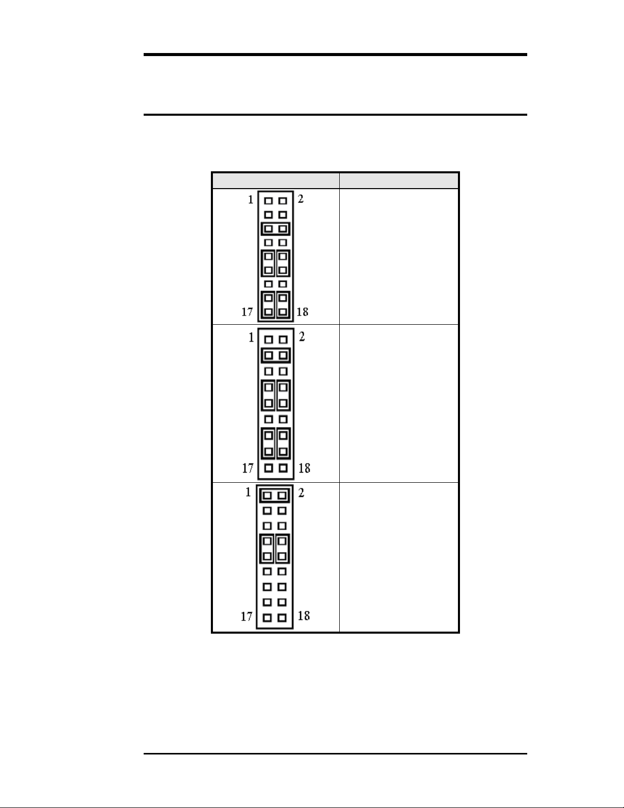
COM2MODE/COM4MODE:
COM2/COM4 RS232/RS422/RS485 Selection
COM2 and COM4 can be configured as RS232/RS-422/RS485 mode.
Below is the Jumper setting table for each mode.
COM2MODE I/F TYPE
RS-232
RS-422
RS-485
ATX-E7 User`s Manual
17
Page 26

Chapter 2 Installations
Connectors on the ATX-E7
The connectors on the ATX-E7 allow you to connect external devices
such as keyboard, floppy disk drives, hard disk drives , printers and etc.
The following table lists the connecto rs on A TX-E7 and th ei r resp ecti v e
page number.
Connector Locations on the ATX-E7.................................19
Front Panel Connector........................................................21
EIDE Connectors ............................................................. 23
Floppy Connectors............................................................ 25
Parallel Port........................................................................26
COM1 Serial Port...............................................................27
COM2 Serial Port...............................................................27
COM3 Serial Port...............................................................28
COM4 Serial Port...............................................................28
PS/2 Keyboard & Mouse Connector..................................29
VGA Connector .................................................................29
CPU Fans Power Connector...............................................30
Chassis Fan Power Connector............................................30
System Fan Connector .......................................................30
USB56 and USB78 Connectors .........................................31
IrDA Connector..................................................................31
Keylock and Power-ON LED Connector...........................31
ATX Power Connector.......................................................32
ATX_12V Power Connector..............................................33
LAN/USB Connectors .......................................................33
LAN- RJ45 Connectors......................................................34
LAN RJ45 LED..................................................................34
LAN LED Connectors.......................................................35
Audio Connectors...............................................................35
CD-IN Connectors .............................................................35
AUX_IN Connectors..........................................................36
SUR_CEN Connectors...................................................... 36
SPDIF Connectors..............................................................36
WOL Connectors ...............................................................37
SATA Connectors..............................................................37
Dio Connectors ..................................................................37
18 ATX-E7 User`s Manual
Page 27

Connector Locations on the ATX-E7
Chapter 2 Installations
PCI1
PCI2
PCI3
PCI4
PCI5
ISA1
AUX_IN
AUDIO
COM2
CD_IN
LAN2
USB34
LAN1
USB12
VGA
LPT
COM1
ISA2
COM3
DIO
COM4
SYSFAN2
SYSFAN1
USB78
LAN2LED
USB56
FLOPPY
LAN1LED
ATX-E7 User`s Manual
19
Page 28

Chapter 2 Installations
K
SUR_CEN SPDIF
AGP
ATX12V
KB+MS
IDE2
IDE1
CPU
FAN
DDR1
DDR2
WOL
SATA1
Front
Panel
IRDA
KEYLOC
SATA2
DDR3
DDR4
PWRFAN
ATX PWR
20 ATX-E7 User`s Manual
Page 29

Chapter 2 Installations
Front Panel Connector
The front panel of the case has a control panel, which provides light
indication of the computer activities and switches to change the
computer status.
EXT PWR HDD PWR RESET KEYLOCK
HDDLED BTM LED LED
EXTHDDLED
This 2-pin connector is used to display the activities of storage
devices which controlled by storage add-on cards like SCSI or
SATA add-on cards. Pull low any one of two pins will make
HDD-LED light up.
IDE LED
Pin #
EXT 1 EXTLED HDDLED 2 EXTLED-
ATX Power ON/OFF Button
This 2-pin connector acts as the “Po we r Supp l y On/Off Switch” on
the ATX-E7 MB. When pressed, the switch will force the MB to
power on. When pressed again, it will force the MB to power off.
IDE LED
Pin #
PWR 3 PWR-BTN
BTN 4 GND
Signal Name
Signal Name
ATX-E7 User`s Manual
21
Page 30

Chapter 2 Installations
IDE Hard Disk LED Connector
This connector connects to the hard drive activity LED on control
panel. This LED will flash when the HDD is being accessed.
IDE LED
Signal Name
Pin #
HDD 5 IDE_ACT
LED 6 Ground
Power-On LED
This connector allows users to connect to Front Panel Power
indicator.
PWR BTN
Signal Name
Pin #
PWR 7 +5V
LED 8 Ground
RESET Switch
The reset switch allows the user to reset the system without turning
the main power switch off and then on. Orientation is not re quired
when making a connection to this header.
RESET
Signal Name
Pin #
RESET 9 Reset
10 Ground
Keylock
For security or other purpose, short these two pins together will
disable the keyboard functions.
PWR BTN
Signal Name
Pin #
KEY 11 Keylock-
LOCK 12 GND
22 ATX-E7 User`s Manual
Page 31

EIDE Connectors
Primary IDE Connector
Signal Name Pin # Pin # Signal Name
Chapter 2 Installations
Reset IDE 1 2 Ground
Host data 7 3 4 Host data 8
Host data 6 5 6 Host data 9
Host data 5 7 8 Host data 10
Host data 4 9 10 Host data 11
Host data 3 11 12 Host data 12
Host data 2 13 14 Host data 13
Host data 1 15 16 Host data 14
Host data 0 17 18 Host data 15
Ground 19 20 Key
DRQ0 21 22 Ground
Host IOW 23 24 Ground
Host IOR 25 26 Ground
IOCHRDY 27 28 Host ALE
DACK0 29 30 Ground
IRQ14 31 32 No connect
Address 1 33 34 No connect
Address 0 35 36 Address 2
Chip select 0 37 38 Chip select 1
Activity 39 40 Ground
ATX-E7 User`s Manual
23
Page 32

Chapter 2 Installations
Secondary IDE Connector
Signal Name Pin # Pin # Signal Name
Reset IDE 1 2 Ground
Host data 5 7 8 Host data 10
Host data 4 9 10 Host data 11
Host data 2 13 14 Host data 13
Host data 1 15 16 Host data 14
Host data 0 17 18 Host data 15
Ground 19 20 Key
DRQ1 21 22 Ground
Host IOW 23 24 Ground
Host IOR 25 26 Ground
IOCHRDY 27 28 Host ALE
DACK1 29 30 Ground
IRQ15 31 32 No connect
Address 1 33 34 No connect
Address 0 35 36 Address 2
Chip select 0 37 38 Chip selec t 1
Activity 39 40 Ground
Host data 7 3 4 Host data 8
Host data 6 5 6 Host data 9
Host data 3 11 12 Host data 12
24 ATX-E7 User`s Manual
Page 33

Chapter 2 Installations
Floppy Connectors
Floppy connector is a 34-pin header and will support up to 2.88MB
floppy drives.
Signal Name Pin # Pin # Signal Name
GND 1 2 DRVDE0
GND 3 4 NC
GND 5 6 DRVDE1
GND 7 8 INDEXGND 9 10 MTR0GND 11 12 DR1GND 13 14 DR0GND 15 16 MTR1GND 17 18 DIRGND 19 20 STEPGND 21 22 WDATAGND 23 24 WGATEGND 25 26 TRK0GND 27 28 WRPROGND 29 30 RDATAGND 31 32 HDSELGND 33 34 DSKCH-
ATX-E7 User`s Manual
25
Page 34

Chapter 2 Installations
Parallel Port
The following drawing shows the location of Parallel port, COM1 and VGA
connector.
The following table describes the pin out assignments of parallel connector.
Signal Name Pin # Pin # Signal Name
Line printer strobe 1 14 AutoFeed
PD0, parallel data 0 2 15 Error
PD1, parallel data 1 3 16 Initialize
PD2, parallel data 2 4 17 Select
PD3, parallel data 3 5 18 Ground
PD4, parallel data 4 6 19 Ground
PD5, parallel data 5 7 20 Ground
PD6, parallel data 6 8 21 Ground
PD7, parallel data 7 9 22 Ground
ACK, acknowledge 10 23 Ground
Busy 11 24 Ground
Paper empty 12 25 Ground
Select 13 N/A
26 ATX-E7 User`s Manual
Page 35

Chapter 2 Installations
COM1 Serial Port
COM1, a 9-pin D-Sub male connector, is the onboard COM1 serial port
of the ATX-E7. The following table shows its pin assignments.
Pin # Signal Name
1 DCD, Data carrier detect
2 RXD, Receive data
3 TXD, Transmit data
4 DTR, Data terminal ready
5 GND, ground
6 DSR, Data set ready
7 RTS, Request to send
8 CTS, Clear to send
9 RI, Ring indicator
COM2 Serial Port
COM2, a 10-pin header connector, is the onboard COM2 serial port of
the ATX-E7. It can be configured as RS233, RS422 and RS485 mode.
User can use COM2MOD jumpers to setup the operation mode. The
following table shows its pin assignments of respective mode.
Pin
#
RS232 Mode
Signal Name
1 DCD, Data carrier
RS422/RS485 Mode
Signal Name
TX- (422/485)
detect
2 RXD, Receive data TX+ (422/485)
3 TXD, Transmit data RX+ (422)
4 DTR, Data terminal
RX- (422)
ready
5 GND, ground GND
6 DSR, Data set ready N.C.
7 RTS, Request to send N.C.
8 CTS, Clear to send N.C.
9 RI, Ring indicator N.C.
10 N.C. N.C.
ATX-E7 User`s Manual
27
Page 36

Chapter 2 Installations
COM3 Serial Port
COM3, a 10-pin header connector, is the onboard COM3 serial port of
the ATX-E7. The following table shows its pin assignments.
Pin
#
RS232 Mode
Signal Name
1 DCD, Data carrier detect
2 RXD, Receive data
3 TXD, Transmit data
4 DTR, Data terminal ready
5 GND, ground
6 DSR, Data set ready
7 RTS, Request to send
8 CTS, Clear to send
9 RI, Ring indicator
10 N.C.
COM4 Serial Port
COM4, a 10-pin header connector, is the onboard COM2 serial port of
the ATX-E7. It can be configured as RS233, RS422 and RS485 mode.
User can use COM4MOD jumpers to setup the operation mode. The
following table shows its pin assignments of respective mode.
Pin
#
RS232 Mode
Signal Name
RS422/RS485 Mode
Signal Name
1 DCD, Data carrier
TX- (422/485)
detect
2 RXD, Receive data TX+ (422/485)
3 TXD, Transmit data RX+ (422)
4 DTR, Data terminal
RX- (422)
ready
28 ATX-E7 User`s Manual
5 GND, ground GND
6 DSR, Data set ready N.C.
7 RTS, Request to send N.C.
8 CTS, Clear to send N.C.
9 RI, Ring indicator N.C.
10 N.C. N.C.
Page 37

Chapter 2 Installations
PS/2 Keyboard & Mouse Connector
The following table describes the pin assignment of PS/2 Keyboard and
Mouse connector.
VGA Connector
Pin # Signal Name
1 Keyboard/Mouse data
2 NC
3 GND
4 5V
5 Keyboard/Mouse clock
6 GND
The pin assignments of VGA CRT connector are as follows:
Signal Name Pin Pin Signal Name
Red 1 2 Green
Blue 3 4 N.C.
GND 5 6 GND
GND 7 8 GND
N.C. 9 10 GND
N.C. 11 12 N.C.
HSYNC 13 14 VSYNC
NC 15
ATX-E7 User`s Manual
29
Page 38

Chapter 2 Installations
CPU Fan Power Connector
This is a 3-pin header for the CPU fan. The fan must be a 12V fan.
Pin # Signal Name
1 Rotation
3 2 1 2 +12V
2 +12V
3 Ground
Chassis Fan Power Connector
This is a 3-pin header for the chassis fan. The fan must be a 12V fan.
Pin # Signal Name
1 Rotation
3 2 1 2 +12V
3 Ground
System FAN Connector
This is a 3-pin header for the system fan. The fan must be a 12V fan.
Pin # Signal Name
1 Rotation
3 2 1 2 +12V
3 Ground
30 ATX-E7 User`s Manual
Page 39

Chapter 2 Installations
USB56 and USB78 Connectors
The following table shows the pin outs of the USB connectors.
1
2
3
4
5
6
USB1
7
8
9
10
Pin#
USB0
Pin #
Signal Name
10 1 +5V
9 2 USB8 3 USB+
7 4 Ground
6 5 N.C.
IrDA Connector
This connector is used for an IrDA connector for wireless
communication.
+5V IRRX IRTX
IrDA Pin # Signal Name
FIR GND
1 +5V
2 FIR
3 Ir RX
4 Ground
5 Ir TX
Keylock and Power-ON LED Connector
The Power LED provide a interface to wire the system power on signal
to front panel. The keylock switch, when closed, will disable the
keyboard function.
Power LED
1
5
Pin #
1 Power_on
2 NC
3 Ground
4 Keylock
5 Ground
Signal Name
ATX-E7 User`s Manual
31
Page 40

Chapter 2 Installations
ATX Power Connector
The ATX power connector supplies power to the whole Main board.
Pin # Signal Name
1 3.3V
2 3.3V
3 GND
4 VCC
5 GND
6 VCC
7 GND
8 Power Good
9 5VSB(stand by +5V)
10 +12V
11 3.3V
12 -12V
13 GND
14 PS_ON(softOn/Off)
15 GND
16 GND
17 GND
18 -5V
19 VCC
20 VCC
32 ATX-E7 User`s Manual
Page 41

Chapter 2 Installations
ATX_12V Power Connector
The ATX_12V power connector mainly supplies power to the CPU.
Caution!
If the ATX_12V power connector is not connected, the system will not
start.
ATX_12V
Pin # Signal Name
1 GND
2 GND
3 +12V
4 +12V
LAN/USB Connectors
Below pictures show the location of LAN RJ45 ports and USB Type-A ports on
the Combo RJ45+ USB connector.
Before you connect your device(s) into USB connector(s), please make
sure your device(s) such as USB keyboard, mouse, scanner, zip,
speaker..etc. Have a standard USB interface. Also make sure your OS
supports USB controller.
If your OS does not support USB controller, please contact OS vendor
for possible patch or driver upgrade. For more information please
contact your OS or device(s) vendors.
ATX-E7 User`s Manual
33
Page 42

Chapter 2 Installations
LAN- RJ45 Connectors
This connector is for the Giga-Bit and 10 /100Mbps Ethernet capability
of the Main Board. The figure below shows the pin out assignme nts of
this connector and its corresponding input jack.
Pin # Signal
Name
1 MDI0+
2 MDI03 MDI1+
4 MDI15 MDI2+
6 MDI27 MDI3+
8 MDI3-
LAN RJ45 LED
The LAN LED on top of RJ45 are to display the current network
connection status. The green color LED on the right-hand side shows the
link status and TX/RX activity. The Yellow/Green Dual color LED on
the left-hand side indicates the operation mode, i.e. 10Base-T,
100Base-T or 1000Base-T.
LNK/ACT STATUS
ON Link
OFF Disconnected
FLASH Packets TX/RX
SPEED MODE
Orange 1 Gbps
Green 100 Mbps
OFF 10 Mbps
34 ATX-E7 User`s Manual
Page 43

Chapter 2 Installations
LAN LED Connectors
The 4-pins LANLED connector designed for each LAN port is for
applications need to display LAN port statu s on front panel o r the places
administrators are easy to access.
LAN LED
Signal Name
Pin #
LAN LED
Audio Connectors
1 ACT2 LINK3 SPD1G4 SPD100M-
After install onboard audio driver, you may connect speaker to Lin Out
jack, microphone to MIC In jack. Audio sources devices like CD-ROM,
walkman and etc can be connected to Lin-In jack.
CD_IN Connectors
CD_IN connector is designed for wire the CD_ROM audio signals to the
on-board Audio CODEC.
LAN LED
Pin #
Signal Name
ATX-E7 User`s Manual
1 CD_Left
2 GND
3 GND
4 CD_Right
35
Page 44

Chapter 2 Installations
AUX_IN Connectors
AUX_IN connector allows you to receive stereo audio inputs from
sound sources such as a TV-Tuner, MPEG card, or CDROM.
LAN LED
Signal Name
Pin #
1 AUX_L
2 GND
3 GND
4 AUX_R
SUR_CEN Connectors
SUR_CEN connector is to support Center Speaker, Rear Surround
Speakers and Low-Frequency Speakers.
Signal Name Pin Pin Signal Name
SURR_OUTL 1 2 SURR_OUTR
GND 3 4 KEY
CENTER_OUT 5 6 LFE_OUT
SPDIF Connectors
SPDIF connector is for S/PDIF audio module that allow digital instead
of analog sound input or output.
Signal Name Pin Pin Signal Name
VCC 1 2 KEY
S_OUT 3 4 S_IN
GND 5 6 GND
36 ATX-E7 User`s Manual
Page 45

Chapter 2 Installations
WOL Connectors
This connector provide the interface between LAN card or Modem card
to wake up system when wake packet or ring-in signals coming in.
Pin # Signal Name
1 5VSB
3 2 1 2 GND
3 PME-
SATA Connectors
These next generation connectors support the thin Serial SATA cables
for Serial ATA Hard disks.
Pin # Signal Name
1 7
1 GND
2 SATARX+
3 SATARX4 GND
5 SATATX6 SATATX+
7 GND
DIO Connectors
DIO port support 8 digital I/O bits. Each bit can be configured as Input or
outputs individually. All bits are 5V tolerant.
Signal Name Pin # Pin # Signal Name
ATX-E7 User`s Manual
+5V 1 2 GND
DIO_0 3 4 DIO_4
DIO_1 5 6 DIO_5
DIO_2 7 8 DIO_6
DIO_3 9 10 DIO_7
37
Page 46

3
BIOS Configuration
This chapter describes the different settings available in the Award
BIOS that comes with the ATX-E7 CPU card. The topics covered in
this chapter are as follows:
BIOS Introduction..................................................................39
Main Menu.............................................................................42
Standard CMOS Setup...........................................................44
Advanced BIOS Features.......................................................50
Advanced Chipset Features....................................................56
Integrated Peripherals.............................................................60
Power Management Setup......................................................68
PnP/PCI Configurations.........................................................72
PC Health Status.....................................................................75
Frequency/Voltage Control....................................................77
Load Fail-Safe Defaults..........................................................78
Load Optimized Defaults .......................................................78
Supervisor/User Password Setting .........................................79
Exit Selecting .........................................................................80
ATX-E7 User`s Manual
38
Page 47

Chapter3 BIOS Configuration
BIOS Introduction
This Chapter discusses Award™ Setup program built into the ATX-E7
BIOS. The Setup program allows users to modify the basic system
configuration. This special information is then stored in
battery-backed RAM so that it retains the Setup information when the
power is turned off.
The AwardBIOS™ installed in ATX-E7 SBC is a custom version of an
industry standard BIOS. This means that it supports Intel PentiumIV in
a standard IBM-AT compatible input/output system. The BIOS
provides critical low-level support for standard devices such as disk
drives and serial and parallel ports.
It also adds non-standard, features such as virus and password
protection as well as special support for detailed fine-tuning of the
chipset controlling the entire system.
The rest of this chapter is intended to guide you through the process of
configuring your system using Setup.
Starting Setup
The AwardBIOS™ is immediately activated when you first power on
the computer. The BIOS reads the system information contained in the
CMOS and begins the process of checking out the system and
configuring it. When it finishes, the BIOS will seek an operating
system on one of the disks and then launch and turn control over to the
operating system.
While the BIOS is in control, the Set up program can be activated in one
of two ways:
1. By press ing <Del> immediately after switching the system on, or
2. by pressing the <Del> key when the following message appears
briefly at the bottom of the screen during the POST (Power On
Self-Test).
Press DEL to enter SETUP.
If the message disappears before you respond and you still wish to enter
Setup, restart the system to try again by turning it OFF then ON or
pressing the "RESET" button on the system case. You may also restart
by simultaneously pressing <Ctrl>, <Alt>, and <Delete> keys. If you
ATX-E7 User`s Manual
39
Page 48

Chapter 3 BIOS Configuration
do not press the keys at the correct time and the system does not boot,
an error message will be displayed and you will again be asked to...
PRESS F1 TO CONTINUE, DEL TO ENTER SETUP
Using Setup
In general, you use the arrow keys to highlight items, press <Enter> to
select, use the PageUp and PageDown keys to change entries, press
<F1> for help and press <Esc> to quit. The following table provides
more detail about how to navigate in the Setup program using the
keyboard.
Key Function
Up Arrow Move to the previous item
Down Arrow Move to the next item
Left Arrow Move to the item on the left (menu bar)
Right Arrow Move to the item on the right (menu bar)
Esc Main Menu: Quit without saving changes
Submenus: Exit Current page to the next higher level
menu
Move Enter Move to the item you desired
PgUp key Increase the numeric value or make changes
PgDn key Decrease the numeric value or make changes
+ key Increase the numeric value or make changes
- key Decrease the numeric value or make changes
Esc key Main Menu -- Quit and not save changes into CMOS
Status Page Setup Menu and Option Page Setup Menu
-- Exit current page and return to Main Menu
F1 key General help on Setup navigation keys
F5 key Load previous values from CMOS
F6 key Load the fail-safe defaults from BIOS default table
F7 key Load the optimized defaults
F10 key Save all the CMOS changes and exit
Navigating through the menu bar
Use the left and right arrow keys to choose the menu you want to be in.
To display a sub menu
Use the arrow keys to move the curs or to the sub menu you want. Then
press <Enter>. A “” pointer marks all sub menus.
40 ATX-E7 User`s Manual
Page 49

Chapter3 BIOS Configuration
Getting Help
Press F1 to pop up a small help window that describes the appropriate
keys to use and the possible selections for the highlighted item. To exit
the Help Window press <Esc> or the F1 key again.
In Case of Problems
If, after making and saving system changes with Setup, you discover
that your computer no longer is able to boot, the AwardBIOS™
supports an override to the CMOS settings which resets your system to
its defaults.
The best advice is to only alter settings that you thoroughly understand.
To this end, we strongly recommend that you avoid making any
changes to the chipset defaults. These defaults have been carefully
chosen by both Award and ATX-E7 manufacturer to provide the
absolute maximum performance and reliability. Even a seemingly
small change to the chipset setup has the potential for causing you to
use the override.
ATX-E7 User`s Manual
41
Page 50

Chapter 3 BIOS Configuration
Main Menu
Once you enter the AwardBIOS™ CMOS Setup Utility, the Main
Menu will appear on the screen. The Main Menu allows you to select
from several setup functions and two exit choices. Use the arrow keys
to select among the items and press <Enter> to accept and enter the
sub-menu.
Phoenix – AwardBIOS CMOS Setup Utility
Standard CMOS Features
Advanced BIOS Features
Advanced Chipset Features
Integrated Peripherals
Power Management Setup
PnP/PCI Configurations
PC Health Status
Esc : Quit ↑ ↓ ← → : Select Item
F10 : Save & Exit Setup
Time, Date, Hard Disk Type….
Note that a brief description of each highlighted selection app ears at the
bottom of the screen.
Frequency/Voltage Control
Load Fail-Safe Defaults
Load Optimized Defaults
Set Supervisor Password
Set User Password
Save & Exit Setup
Exit Without Saving
Setup Items
The main menu includes the following main setup categories.
Standard CMOS Features
Use this menu for basic system configuration.
Advanced BIOS Features
Use this menu to set the Advanced Features available on your system.
42 ATX-E7 User`s Manual
Page 51

Chapter3 BIOS Configuration
Advanced Chipset Features
Use this menu to chan ge the values in th e chipset registers an d optimize
your system's performance.
Integrated Peripherals
Use this menu to specify your settings for integrated peripherals.
Power Management Setup
Use this menu to specify your settings for power management.
PnP / PCI Configuration
Use this menu to set up the PnP/PCI configuration.
PC Health Status
Use this menu to display the CPU temperature, FAN speed and
voltages.
Frequency/Voltage Control
Use this menu to specify your settings for frequency/voltage control.
Load Fail-Safe Defaults
Use this menu to load the BIOS default values for the minimal/stable
performance for your system to operate.
Load Optimized Defaults
Use this menu to load the BIOS default values that are factory settings
for optimal performance system operations. While Award has designed
the custom BIOS to maximize performance, the factory has the right to
change these defaults to meet their needs.
Supervisor / User Password
Use this menu to set User and Supervisor Passwords.
Save & Exit Setup
Save CMOS value changes to CMOS and exit setup.
Exit Without Save
Abandon all CMOS value changes and exit setup.
ATX-E7 User`s Manual
43
Page 52

Chapter 3 BIOS Configuration
Standard CMOS Setup
The items in Standard CMOS Setup Menu are divided into 10
categories. Each category includes no, one or more than one setup
items. Use the arrow keys to highlight the item and then use the
<PgUp> or <PgDn> keys to select the value you want in each item.
Phoenix – AwardBIOS CMOS Setup Utility
Standard CMOS Features
Date: Mon, Feb 8 2004
Time: 16 : 19 : 20
IDE Channel 0 Master [Maxtor 6E040L0]
IDE Channel 0 Slave [None]
IDE Channel 1 Master [None]
IDE Channel 1 Slave [None]
Drive A [1.44M, 3.5 in.]
Drive B [None]
Video [EGA/VGA]
Halt On [All , But Disk/Key]
Base Memory 640K
Extended Memory 1046528K
Total Memory 1047552K
↑↓←→Move Enter: Select +/-/PU/PD: Value F10:Save ESC: Exit F1:General Help
F5:Previous Values F6:Fail-safe Defaults F7:Optimized Defaults
Item Help
Menu Level
Change the day, month,
year and century
44 ATX-E7 User`s Manual
Page 53

Chapter3 BIOS Configuration
This table shows the selections that you can make on the
Standard CMOS Menu
Item Options Description
Date Month DD YYYY Set the system date.
Note that the ‘Day’ automatically
changes when you set the date
Time HH : MM : SS Set the system time
IDE Channel 0 Master Options are in its sub menu Press <Enter> to enter the sub
menu of detailed options
IDE Channel 0 Slave Options are in its sub menu Press <Enter> to enter the sub
menu of detailed options
IDE Channel 1 Master Options are in its sub menu Press <Enter> to enter the sub
menu of detailed options
IDE Channel 1 Slave Options are in its sub menu Press <Enter> to enter the sub
menu of detailed options
Drive A
Drive B
Video EGA/VGA
Halt On All Errors
Base Memory N/A Displays the amount of
Extended Memory N/A Displays the amount of extended
Total Memory N/A Displays the total memory
None
360K, 5.25 in
1.2M, 5.25 in
720K, 3.5 in
1.44M, 3.5 in
2.88M, 3.5 in
CGA 40
CGA 80
MONO
No Errors
All, but Keyboard
All, but Diskette
All, but Disk/Key
Select the type of floppy disk drive
installed in your system
Select the default video device
Select the situation in which you
want the BIOS to stop the POST
process and notify you
conventional memory detected
during boot up
memory detected during boot up
available in the system
ATX-E7 User`s Manual
45
Page 54

Chapter 3 BIOS Configuration
Channel 0 HDDs / Channel 1 HDDs
The IDE adapters control the hard disk drive. Use a separate sub m enu
to configure each hard disk drive. Figure 2 shows the IDE primary
master sub menu.
Phoenix – AwardBIOS CMOS Setup Utility
IDE Cannel 0 Master
IDE HDD Auto-Detection [Press Enter]
IDE Channel 0 Master [Auto]
Access Mode [Auto]
Capacity 41111 MB
Cylinder 19679
Head 16
Precomp 0
Landing Zone 19678
Sector 255
↑↓←→Move Enter: Select +/-/PU/PD:Value F10:Save ESC:Exit F1:General Help
F5:Previous Values F6:Fail-safe Defaults F7:Optimized Defaults
Menu Level
To auto-detect the HDD’s
size, head... on this channel
Item Help
Phoenix – AwardBIOS CMOS Setup Utility
IDE Cannel 0 Slave
IDE HDD Auto-Detection [Press Enter]
IDE Channel 0 Slave [Auto]
Access Mode [Auto]
Capacity 0 MB
Cylinder 0
Head 0
Precomp 0
Landing Zone 0
Sector 0
↑↓←→Move Enter: Select +/-/PU/PD:Value F10:Save ESC:Exit F1:General Help
F5:Previous Values F6:Fail-safe Defaults F7:Optimized Defaults
Menu Level
To auto-detect the HDD’s
size, head... on this channel
Item Help
Use the legend keys to navigate through this menu and exit to the main
menu. Use the Table listed below to configure the hard disk.
46 ATX-E7 User`s Manual
Page 55

Chapter3 BIOS Configuration
Item Options Description
IDE HDD
Auto-detection
Press Enter Press Enter to auto-detect the
HDD on this channel. If
detection is successful, it fills the
remaining fields on this menu.
IDE Channel 0 Master None
Auto
Manual
Selecting ‘manual’ lets you set
the remaining fields on this
screen. Selects the type of fixed
disk. "User Type" will let you
select the number of cylinders,
heads, etc.
Note: PRECOMP=65535 means
NONE !
Capacity Auto Display yo ur
disk drive size
Disk drive capacity
(Approximated). Note that this
size is usually slightly greater
than the size of a formatted disk
given by a disk checking
program.
Access Mode CHS
LBA
Choose the access mode for this
hard disk
Large
Auto
The following options are selectable only if the ‘IDE Channel 0 Master’ item is
set to ‘Manual’
Cylinder Min = 19679
Max = 65535
Head Min = 16
Max = 255
Precomp Min = 0
Max = 65535
Landing zone Min = 19678
Set the number of cylinders for
this hard disk.
Set the number of read/write
heads
**** Warning: Setting a value of
65535 means no hard disk
****
Max = 65535
Sector Min = 255
Number of sectors per track
Max = 255
ATX-E7 User`s Manual
47
Page 56

Chapter 3 BIOS Configuration
Item Options Description
IDE HDD
Auto-detection
Press Enter Press Enter to auto-detect the
HDD on this channel. If
detection is successful, it fills the
remaining fields on this menu.
IDE Channel 0 Slave None
Auto
Manual
Selecting ‘manual’ lets you set
the remaining fields on this
screen. Selects the type of fixed
disk. "User Type" will let you
select the number of cylinders,
heads, etc.
Note: PRECOMP=65535 means
NONE !
Capacity Auto Display your
disk drive size
Disk drive capacity
(Approximated). Note that this
size is usually slightly greater
than the size of a formatted disk
given by a disk checking
program.
Access Mode CHS
LBA
Choose the access mode for this
hard disk
Large
Auto
The following options are selectable only if the ‘IDE Channel 0 Master’ item is
set to ‘Manual’
Cylinder Min = 0
Max = 65535
Head Min = 0
Max = 255
Precomp Min = 0
Max = 65535
Landing zone Min = 0
Set the number of cylinders for
this hard disk.
Set the number of read/write
heads
**** Warning: Setting a value of
65535 means no hard disk
****
Max = 65535
Sector Min = 0
Number of sectors per track
Max = 255
48 ATX-E7 User`s Manual
Page 57

Chapter3 BIOS Configuration
Drive A / Drive B
These fields identify the types of floppy disk drive A or drive B that has
been installed in the computer. The available specifications are:
Non 360KB
5.25 in.
5.25 in.
1.
2MB
720KB
3.5 in.
1.
44MB
3.5 in.
2.
88MB
3.5 in.
Video
This field selects the type of video display card installed in your system.
You can choose the following video display cards:
EGA/VGA For EGA, VGA, SEGA, SVGA
or PGA monitor adapters. (default)
CGA 40 Power up in 40 column mode.
CGA 80 Power up in 80 column mode.
MONO For Hercules or MDA adapters.
Halt On
This field determines whether the syst em will halt if an error is detected
during power up.
All errors Whenever the BIOS detects a non-fatal error,
the system will stop and you will be prompted.
No errors The system boot will not be halted for any error
that may be detected. (default)
All, But Keyboard The system boot will not be halted for a
keyboard error; it will stop for all other errors
All, But Diskette The syste m boot will not be halted for a disk
error; it will stop for all other errors.
All, But Disk/Key The system boot will not be halted for a key-
board or disk error; it will stop for all others.
ATX-E7 User`s Manual
49
Page 58

Chapter 3 BIOS Configuration
Advanced BIOS Features
This section allows you to configure your system for basic operation.
You have the opportunity to select the system’s default speed, boot-up
sequence, keyboard operation, shadowing and security.
Phoenix – AwardBIOS CMOS Setup Utility
Advanced BIOS Features
CPU Feature [Press Enter]
Hard Disk Boot Priority [Press Enter]
Virus Warning [Disabled]
CPU L1 and L2 Cache [Enabled]
Hyper-Threading Technology [Enabled]
Quick Power On Self Test [Enabled]
First Boot Device [Floppy]
Second Boot Device [HDD]
Third Boot Device [LS120]
Boot Other Device [Enabled]
Swap Floppy Drive [Disabled]
Boot Up Floppy Seek [Enabled]
Boot Up NumLock Status [Off]
Gate A20 Option [Fast]
Typematic Rate Setting [Disabled]
x Typematic Rate (Chars/Sec) 6
x Typematic Delay (Msec) 250
Security Option [Setup]
x APC Mode Enabled
MPS Version Control For OS [1.4]
OS Select For DRAM > 64MB [Non-OS2]
Report No FDD For Win95 [No]
↑↓←→Move Enter: Select +/-/PU/PD: Value F10:Save ESC: Exit F1:General Help
F5:Previous Values F6:Fail-safe Defaults F7:Optimized Defaults
Item Help
Menu Level
Allows you to choose the
VIRUS warning feature for
IDE Hard Disk boot sector
protection. If this function is
enabled and someone
attempt to write data into
this area, BIOS will show a
warning message on screen
and alarm beep
50 ATX-E7 User`s Manual
Page 59

Chapter3 BIOS Configuration
Phoenix – AwardBIOS CMOS Setup Utility
CPU Feature
Delay Prior Thermal [16Min]
Thermal Management Thermal Monitor 1
↑↓←→Move Enter: Select +/-/PU/PD: Value F10: Save ESC: Exit F1 :General Help
F5:Previous Values F6:Fail-safe Defaults F7:Optimized Defaults
Item Help
Menu Level
Delay Prior Thermal
The choice: 4Min, 8Min, 16Min, 32Min.
Thermal Management
ATX-E7 User`s Manual
51
Page 60

Chapter 3 BIOS Configuration
Phoenix – AwardBIOS CMOS Setup Utility
Hard Disk Boot Priority
1.Ch0 M. :Maxtor 6E040L0
2. Bootable Add-in Cards
↑↓←→Move Enter: Select +/-/PU/PD: Value F10:Save ESC: Exit F1:General Help
F5:Previous Values F6:Fail-safe Defaults F7:Optimized Defaults
Item Help
Menu Level
Use <↑> or <↓> to select a
device, then press <+> to
move it up, or <-> to move
it down the list. Press
<ESC> to exit this menu
Ch0 M. :Maxtor 6E040L0
Use <↑> or <↓> to select a device, then press <+> to move it up, or <
-
> to move it down the list. Press <ESC> to exit this menu.
Bootable Add-in Cards
Use <↑> or <↓> to select a device, then press <+> to move it up, or <
-
> to move it down the list. Press <ESC> to exit this menu.
Virus Warning
Allows you to choose the VIRUS Warning feature for IDE Hard Disk
boot sector protection. If this function is enabled and someone attempt
to write data into this area, BIOS will show a warning message on
screen and alarm beep.
Enabled Activates automat ically when the system boots up causing a
warning message to appear when anything attempts to
access the boot sector or hard disk partition table.
Disabled No warning message will appear when anything attempts to
access the boot sector or hard disk partition table.
52 ATX-E7 User`s Manual
Page 61

Chapter3 BIOS Configuration
CPU L1 & L2 Cache
These two categories speed up me mory access. However, it depends
on CPU/chipset design.
Enabled Enable cache
Disabled Disable cache
Hyper-Threading Technology
This setting allows user to enable or disable Hyper-Threading
technology. If the CPU installed does not support Hyper-Threading
Technlogy, this item will not show up.
The choice: Enabled/Disabled.
Quick Power On Self Test
Allows the system to skip certain tests while booting. This will
decrease the time needed to boot the system.
Enabled Enable quick POST
Disabled Normal POST
First/Second/Third/Other Boot Device
The BIOS attempts to load the operat ing system from the devices i n the
sequence selected in these items.
The Choice: Floppy, LS120, ZIP100, HDD, CDROM, LAN, Disabled,
USB-FDD, USB-ZIP, USB-CDROM.
Swap Floppy Drive
If the system has two floppy drives, choose enable to assign physical
drive B to logical drive A and vice-versa.
The choice: Enabled/Disabled.
Boot Up Floppy Seek
Enabled tests floppy drives to determine whether they have 40 or 80
tracks.
The choice: Enabled/Disabled.
ATX-E7 User`s Manual
53
Page 62

Chapter 3 BIOS Configuration
Boot Up NumLock Status
Selects power on state for NumLock.
The choice: On/Off.
Gate A20 Option
Select if chipset or keyboard controller should control GateA20.
Normal A pin in the keyboard controller controls GateA20
Fast Lets chipset control GateA20
Typematic Rate Setting
Keystrokes repeat at a rate determined by the keyboard controller.
When enabled, the typematic rat e an d typematic delay can be selected.
The choice: Enabled/Disabled.
Typematic Rate (Chars/Sec)
Sets the number of times a secon d to repeat a key stroke when you hold
the key down.
The choice: 6, 8, 10, 12, 15, 20, 24, 30.
Typematic Delay (Msec)
Sets the delay time after the key is held down before it begins to repeat
the keystroke.
The choice: 250, 500, 750, 1000.
Security Option
Select whether the password is required every time the system boots or
only when you enter setup.
System The syste m will not boot and access to Setup will be
denied if the correct password is not entered at the
prompt.
Setup The system will boot, but access to Setup will be
denied if the correct password is not entered at the
prompt.
54 ATX-E7 User`s Manual
Page 63

Chapter3 BIOS Configuration
Note: To disable security, select PASSWORD SETTING at Main
Menu and then you will be asked to enter password. Do not type
anything and just press <Enter>, it will disable security. Once the
security is disabled, the system will boot and you can enter Setup
freely.
APIC Mode
The choice: Enabled/Disabled.
MPS Version Control For OS
The choice: 1.1, 1.4.
OS Select For DRAM > 64MB
Select the OS2 only if you are running OS/2 operating system with
greater than 64MB of RAM on the system.
The choice: Non-OS2, OS2.
Report No FDD For WIN 95
This option allows Windows 95 to share with other pe ripherals IRQ6
which is assigned to a floppy disk drive if the drive is not existing. The
default setting is No.
The choice: Yes, No.
ATX-E7 User`s Manual
55
Page 64

Chapter 3 BIOS Configuration
Advanced Chipset Features
Phoenix – AwardBIOS CMOS Setup Utility
Advanced Chipset Features
DRAM Timing Selectable [By SPD]
x CAS Latency Time [3]
x Active to Precharge Delay [8]
x DRAM RAS# to CAS# Delay [4]
x DRAM RAS# Precharge [4]
Memory Frequency For [Auto]
System BIOS Cacheable [Enabled]
Video BIOS Cacheable [Disabled]
Memory Hole At 15M-16M [Disabled]
AGP Aperture Size (MB) [128]
Init Display First [PCI Slot]
***On-Chip VGA Setting***
On-Chip VGA [Enabled]
On-Chip Frame Buffer Size [16MB]
Item Help
Menu Level
↑↓←→Move Enter: Select +/-/PU/PD: Value F10:Save ESC: Exit F1:General Help
F5:Previous Values F6:Fail-safe Defaults F7:Optimized Defaults
This section allows you to configur e the system based on the specific
features of the installed chipset. This chipset manages bus speeds and
access to system memory resources, such as DRAM and the external
cache. It also coordinates communications between the conventional
ISA bus and the PCI bus. It must be stated that these items should never
need to be altered. The default settings have been chosen be cause they
provide the best operating conditions for your system. The only time
you might consider making any changes would be if you discovered
that data was being lost while using your system.
DRAM Settings
The first chipset settings deal with CPU access to dynamic random
access memory (DRAM). The default timings have been carefully
chosen and should only be altered if data is being lost. Such a scenario
might well occur if your system had mixed speed DRAM chips
installed so that greater delays may be required to preserve the integrity
of the data held in the slower memory chips.
56 ATX-E7 User`s Manual
Page 65

Chapter3 BIOS Configuration
DRAM Timing Selectable
This item allows you to select the DRAM timing determined by the
timing information stored in SPD or set by the User manually. The
default is By SPD. Wh en this field is set as By SPD, the DRAM Timing
items below will become read-only.
The choice: By SPD, Manual.
CAS Latency Time
When synchronous DRAM is installed, the number of clock cycles of
CAS latency depends on the DRAM timing. Do not reset this field
from the default value specified by the system designer.
The choice: 3, 2.5, 2, 1.5.
Active to Precharge Delay
This item allows you to set the Active to Precharge D elay of DRAM
timing. Do not reset this field from the default value specified by the
system designer.
The choice: 8, 7.
DRAM RAS# to CAS# Delay
When DRAM is refreshed, both rows and columns are addressed
separately. This field allows you to determine the timing of transition
from Row Address Strobe (RAS) to Column Address Strobe (CAS).
The choice: 4, 3.
DRAM RAS# Precharge
The precharge time is the number of cycles it takes for the RAS to
accumulate its charge before DRAM refresh. If insufficient time is
allowed, refresh may be inco mplete and the DRAM may fail to retain
data.
The choice: 4, 3.
ATX-E7 User`s Manual
57
Page 66

Chapter 3 BIOS Configuration
Memory Frequency For
This item allows user to set the DDR DRAM operation frequency. The
Auto is default.
The choice: DDR266, DDR320, DDR400, Auto.
System BIOS Cacheable
Selecting Enabled allows caching of the system BIOS ROM at
F0000h-FFFFFh, resulting in better system performance. H owever, if
any program writes to this memory area, a system error may result.
The choice: Enabled, Disabled.
Video BIOS Cacheable
Selecting Enabled allows caching of the Video BIOS ROM, resulting
in better system performance. However, if any program writes to this
memory area, a system error may result.
The choice: Enabled, Disabled.
Memory Hole at 15MB - 16MB
In order to improve performance, certain space in memory can be
reserved for IS A cards. This fi eld allows y ou to reserve 1 5MB to 16MB
memory address space to ISA expansion cards. This makes memory
from 15MB and up unavailable to the system. Expansion cards can
only access memory up to 16MB. The default of this field is set to
Disabled.
The choice: Enabled, Disabled.
AGP Aperture Size (MB)
Select the size of Accelerated Graphics Port (AGP) aperture. The
aperture is a portion of the PCI me mory address range dedicated for
graphics memory address space. Host cy cles that hit the aperture ran ge
are forwarded to the AGP without any translation.
The choice: 4M, 8M, 16M, 32M, 64M, 128M, 256M.
58 ATX-E7 User`s Manual
Page 67

Chapter3 BIOS Configuration
Init Display First
This item define the Display device scan sequence. If CPI Slot is
selected, System BIOS will scan the PCI display on PCI bus first. If
PCI display card detected, it will become the display device. Otherwise,
BIOS will use integrated graphic de vic e.
The choice: PCI Slot, Onboard/AGP
On-Chip VGA Setting
On-Chip VGA
The choice: Enabled, Disabled.
On-Chip Frame Buffer Size
The choice: 1MB, 8MB, 16MB.
ATX-E7 User`s Manual
59
Page 68

Chapter 3 BIOS Configuration
Integrated Peripherals
Phoenix – AwardBIOS CMOS Setup Utility
Integrated Peripherals
OnChip IDE Device [Press Enter]
Onboard Device [Press Enter]
SuperIO Device [Press Enter]
Onboard Serial Port 3 [3E8]
Serial Port 3 Use IRQ [IRQ7]
Onboard Serial Port 4 [2E8]
Serial Port 4 Use IRQ [IRQ7]
↑↓←→ Move Enter: Select +/-/PU/PD: Value F10:Save ESC: Exit F1:General Help
F5:Previous Values F6:Fail-safe Defaults F7:Optimized Defaults
Item Help
Menu Level
Phoenix – AwardBIOS CMOS Setup Utility
OnChip IDE Device
IDE HDD Block Mode [Enabled]
IDE DMA transfer access [Enabled]
On-Chip Primary PCI IDE [Enabled]
IDE Primary Master PIO [Auto]
IDE Primary Slave PIO [Auto]
IDE Primary Master UDMA [Auto]
IDE Primary Slave UDMA [Auto]
On-Chip Secondary PCI IDE [Enabled]
IDE Secondary Master PIO [Auto]
IDE Secondary Slave PIO [Auto]
IDE Secondary Master UDMA [Auto]
IDE Secondary Slave UDMA [Auto]
***On-Chip Serial ATA Setting***
x SATA Mode IDE
On-Chip Serial ATA [Auto]
x Serial ATA Port0 Mode SATA0 master
Serial ATA Port1 Mode SATA1 master
↑↓←→ Move Enter: Select +/-/PU/PD: Value F10:Save ESC: Exit F1:General Help
F5:Previous Values F6:Fail-safe Defaults F7:Optimized Defaults
Item Help
Menu Level
If your IDE hard drive
supports block mode
select Enabled for
automatic detection of
the optimal number of
block read/writes per
sector the drive can
support
60 ATX-E7 User`s Manual
Page 69

Chapter3 BIOS Configuration
IDE HDD Block Mode
If your IDE hard drive supports block mode select Enabled for
automatic detection of the optimal number of block read/writes per
sector the drive can support
The choice: Enabled, Disabled.
IDE DMA transfer acess
The choice: Enabled, Disabled.
On-Chip Primary PCI IDE
The chipset contains a PCI IDE interface with support for two IDE
channels. Select Enabled to activate the primary IDE interface. Select
Disabled to deactivate this interface
The choice: Enabled, Disabled.
On-Chip Secondary PCI IDE
The chipset contains a PCI IDE interface with support for two IDE
channels. Select Enabled to activate the secondary IDE interface.
Select Disabled to deactivate this interface
The choice: Enabled, Disabled.
IDE Primary/Secondary Master/Slave PIO
The four IDE PIO (Programmed Input/Output) fields let you set a PIO
mode (0-4) for each of the four IDE devices that the onboard IDE
interface supports. Modes 0 through 4 provide successively increased
performance. In Auto mode, the system automatically determines the
best mode for each device.
The choice: Auto, Mode 0, Mode 1, Mode 2, Mode 3, Mode 4.
ATX-E7 User`s Manual
61
Page 70

Chapter 3 BIOS Configuration
IDE Primary/Secondary Master/Slave UDMA
Ultra DMA/33/66/100 implementation is possible only if your IDE
hard drive and cable supports it and the operating environment includes
a UDMA driver If your hard drive and your system software both
support Ultra DMA/33/66/100, select Auto to enable BIOS support.
The System BIOS will also check the IDE cable. Only if the 80-way
ATA66/100 cable is installed, the ATA66/100 models can be enabled
by the OS driver. Otherwise, the system will be limited to run up to
ATA33 mode.
The Choice: Auto, Disabled.
On-Chip Serial ATA Setting
SATA Mode
On-Chip Serial ATA
Disabled Disabled SATA Controller.
Auto Auto arrange by BIOS.
Combined
Mode
Enhanced
Mode
PATA and SATA are combined. Max. of 2 IDE
drives in each channel.
Enable both SATA and PATA. Max. of 6 IDE
drives are supported.
SATA Only SATA is operating in legacy mode
Serial ATA Port0 Mode
The choice: Primary Master, Primary Slave, Secondary Master,
Secondary Slave, Primary M aster, Secondary Maste r, SATA0 master,
SATA1 master.
Serial ATA Port1 Mode
The choice: Primary Master, Primary Slave, Secondary Master,
Secondary Slave, Primary M aster, Secondary Maste r, SATA0 master,
SATA1 master.
62 ATX-E7 User`s Manual
Page 71

Chapter3 BIOS Configuration
Phoenix – AwardBIOS CMOS Setup Utility
Onbord Device
USB Controller [Enabled]
USB 2.0 Controller [Enabled]
USB Keyboard Support [Disabled]
USB Mouse Support [Disabled]
AC97 Audio [Auto]
↑↓←→ Move Enter: Select +/-/PU/PD: Value F10:Save ESC: Exit F1:General Help
F5:Previous Values F6:Fail-safe Defaults F7:Optimized Defaults
Item Help
Menu Level
USB Controller
This should be enabled if your system has a USB installed on the
system board and you wish to use it. Even when so equipped, if you add
a higher performance controller, you will need to disable this feature.
The choice: Enabled, Disabled.
USB 2.0 Controller
This entry is for disable/enable EHCI controller only. This BIOS itself
may/may not have high speed USB support. If the BIOS has high speed
USB support built in, the support will be automatically turn on when
high speed device were attached.
The choice: Enabled, Disabled.
USB Keyboard Support
Select Enabled if your system contains a Universal Serial Bus (USB)
controller and you have a USB keyboard.
The choice: Enabled, Disabled.
ATX-E7 User`s Manual
63
Page 72

Chapter 3 BIOS Configuration
USB Mouse Support
The choice: Enabled, Disabled.
AC97 Audio
The choice: Auto, Disabled.
64 ATX-E7 User`s Manual
Page 73

Chapter3 BIOS Configuration
Phoenix – AwardBIOS CMOS Setup Utility
SuperIO Device
Onboard FDC Controller [Enabled]
Onboard Serial Port 1 [3F8/IRQ4]
Onboard Serial Port 2 [2F8/IRQ3]
UART Mode Select [Normal]
x RxD , TxD Active Hi, Lo
x IR Transmission Delay Enabled
x UR2 Duplex Mode Half
Onboard Parallel Port [378/IRQ7]
Parallel Port Mode [SPP]
x EPP Mode Select EPP1.7
x ECP Mode Use DMA 3
PWRON After PWR-Fail [Off]
↑↓←→ Move Enter: Select +/-/PU/PD: Value F10:Save ESC: Exit F1:General Help
F5:Previous Values F6:Fail-safe Defaults F7:Optimized Defaults
Item Help
Menu Level
Onboard FDC Controller
Select Enabled if your system has a floppy disk controller (FDC)
installed on the system board and you wish to use it. If you install
and-in FDC or the system has no floppy drive, select Disabled in this
field.
The choice: Enabled, Disabled.
Onboard Serial Port 1/Port 2
Select an address and corresponding interrupt for the first and second
serial ports.
The choice: 3F8/IRQ4, 2F8/IRQ3, 3E8/IRQ4, 2E8/IRQ3, Disabled,
Auto.
UART Mode Select
The choice: IrDA, ASKIR, Normal.
RxD, TxD Active
This item allows you to choose Hi-A ctive or Low-Active of TX and
RX signlal, which depends on different H/W requirement. This field is
ATX-E7 User`s Manual
65
Page 74

Chapter 3 BIOS Configuration
not recommended to change its default setting for avoiding any error in
your system
The Choice: Hi, Hi / Hi, Lo (Default) / Lo, Hi / Lo, Lo.
IR Transmission Delay
This item allows you to Enable/Disable IR tranismission delay.
The choice: Enabled, Disabled.
UR2 Duplex Mode
This item allows you to select the IR half/full duplex function.
The Choice: Half, Full.
Onboard Parallel Port
This item allows you to determine onboard parallel port controller I/O
address setting.
The choice: 378/IRQ7, 278/IRQ5, 3BC/IRQ7, Disabled.
Parallel Port Mode
Select an operating mode for the onboard paral lel (print er) port. Select
Normal, Compatible, or SPP unless you ar e c ertain your hardware and
software both support one of the other available modes.
The choice: SPP, EPP, ECP, ECP+EPP, Normal.
EPP Mode Select
Select EPP port type 1.7 or 1.9.
The choice: EPP1.7, 1.9.
ECP Mode Use DMA
Select a DMA channel for the parallel port for use during ECP mode.
The choice: 3, 1.
PWRON After PWR-Fail
The choice: Off, On, Former-Sts.
66 ATX-E7 User`s Manual
Page 75

Chapter3 BIOS Configuration
Onboard Serial Port3/Port4
The choice: Disabled, 4F8, 4E8, 3E8, 2E8.
Serial Port 3 Use IRQ/ Port 4 Use IRQ
The choice: IRQ3, IRQ4, IRQ5, IRQ7, IRQ9, IRQ10.
ATX-E7 User`s Manual
67
Page 76

Chapter 3 BIOS Configuration
Power Management Setup
The Power Management Setup allows you to configur e you system to
most effectively save energy while operating in a manner consistent
with your own style of computer use.
Phoenix – AwardBIOS CMOS Setup Utility
Power Management Setup
Power-Supply Type [ATX]
ACPI Function [Enabled]
Power Management [User Define]
Video Off Method [DPMS]
Video Off In Suspend [Yes]
MODEM Use IRQ [3]
Suspend Mode [Disabled]
HDD Power Down [Disabled]
Soft-Off by PWR-BTTN [Instant-Off]
CPU THRM-Throttling [50.0%]
Wake-Up by PCI Card [Enabled]
Power On by Ring [Enabled]
Wake Up On LAN [Enabled]
Resume by Alarm [Disabled]
x Date (of Month) Alarm 0
x Time (hh:mm:ss) Alarm 0 : 0 : 0
** Reload Global Timer Events **
Primary IDE 0 [Disabled]
Primary IDE 1 [Disabled]
Secondary IDE 0 [Disabled]
Secondary IDE 1 [Disabled]
FDD, COM, LPT Port [Disabled]
PCI PIRQ[A-D]# [Disabled]
↑↓←→Move Enter: Select +/-/PU/PD: Value F10:Save ESC: Exit F1:General Help
F5:Previous Values F6:Fail-safe Defaults F7:Optimized Defaults
Item Help
Menu Level
Power-Supply Type
This should be AT if you use AT power supply or ATX power supply
but force to AT mode. This selection help BIOS provide the
information to OS what kind power-supply t he system use. The correct
information provide to OS can avoid the Windows Shutdown issue.
The choice: AT, ATX.
68 ATX-E7 User`s Manual
Page 77

Chapter3 BIOS Configuration
ACPI Function
This item allows you to enable/disable the Advanced Configuration
and Power Management (ACPI).
The choice: Enabled, Disabled.
Power Management
This category allows you to select the type (or degree) of power saving
and is directly related to the following modes:
1. HDD Power Down
2. Suspend Mode
There are three selections for Power Management, three of which have
fixed mode settings.
Disable (default) No power management. Disables all four modes
Min. Power Saving Minimum power management. Suspend Mode = 1
hr., and HDD Power Down = 15 min.
Max. Power
Saving
Maximum power management. Suspend Mode = 1
min., and HDD Power Down = 1 min.
User Defined Allows you to set each mode individually. The
Suspend mode ranges are from 1 min. to 1 hr. The
HDD Power Down ranges are from 1 min. to 15
min. and disable.
Video Off Method
This determines the manner in which the monitor is blanked.
V/H SYNC+Blank This selection will cause the system to turn off the
vertical and horizontal synchronization ports a nd
write blanks to the video buffer.
Blank Screen This option only writes blanks to the video buffer.
DPMS Initial display power management signaling.
Allows the BIOS to control video display card if
it supports the DPMS feature.
ATX-E7 User`s Manual
69
Page 78

Chapter 3 BIOS Configuration
Video Off In Suspend
This determines the if the turn off the video display when system enter
suspend mode.
The choice: Yes, No.
MODEM Use IRQ
This determines the IRQ in which the MODEM can use.
The choice: 3, 4, 5, 7, 9, 10, 11, NA.
Suspend Mode
When enabled and after the set time of system inactivity, CPU will be
put into the suspend mode.
The choice: Disabled, 1 min, 2 min, 4 m in,8min, 12min, 20min, 30min,
40min, 1 hour.
HDD Power Down
When enabled and after the set time of system inactivity, the hard disk
drive will be powered down while all other devices remain active.
The choice: Disabled, 1 min, 2 min, 4 min, ….. 15 min.
Soft-Off by PWR-BTTN
The choice: Instant-Off, Delay 4 Sec.
CPU THRM-Throttling
The choice: 75.0%, 50.0%, 25.0%
Wake-Up by PCI card
The choice: Enabled, Disabled.
70 ATX-E7 User`s Manual
Page 79

Chapter3 BIOS Configuration
Power On By Ring
An input signal on the serial Ring Indicator (RI) line (in other words, an
ncoming call on the modem) awakens the system from a soft off state.
The choice: Enabled, Disabled.
Wake Up On LAN
The choice: Enabled, Disabled.
Resume by Alarm
When Enabled, your can set the date and time at which the RTC
(real-time clock) alarm awakens the system from Suspend mode.
The choice: Enabled, Disabled.
Reload Global Timer Events
PM events are I/O events whose occurrence can prevent the system
from entering a suspend mode or can awaken the system from such a
mode. In effect, the system remain s al ert for anything which occurs to
a device which is configured as Enabled, even when the system is in a
Suspend down mode.
Primary/Secondary IDE 0/1
When Enabled, any activity from one of the listed system peripheral
devices or IRQs wakes up the system.
The choice: Enabled, Disabled.
FDD, LPT & COM
When Enabled, any activity from one of the listed system peripheral
devices or IRQs wakes up the system.
The choice: Enabled, Disabled.
PCI PIRQ[A-D]#
When Enabled, any activity from one of the listed PCI IRQ signals
wakes up the system.
The choice: Enabled, Disabled.
ATX-E7 User`s Manual
71
Page 80

Chapter 3 BIOS Configuration
PnP/PCI Configuration Setup
This section describes configuring the PCI bus system. PCI, or
Personal Computer Interconnect, is a system which allows I/O devices
to operate at speeds nearing the speed the CPU itself uses when
communicating with its own special components. This section covers
some very technical items and it is strongly recommended that only
experienced users should make any changes to the default settings.
Phoenix – AwardBIOS CMOS Setup Utility
PnP/PCI Configurations
PnP OS Installed [No]
Reset Configuration Data [Disabled]
Resources Controlled By [Auto(ESCD)]
x IRQ Resources Press Enter
x Memory Resources Press Enter
PCI/VGA Palette Snoop [Disabled]
INT Pin1 Assignment [Auto]
INT Pin2 Assignment [Auto]
INT Pin3 Assignment [Auto]
INT Pin4 Assignment [Auto]
INT Pin5 Assignment [Auto]
INT Pin6 Assignment [Auto]
INT Pin7 Assignment [Auto]
INT Pin8 Assignment [Auto]
↑↓←→Move Enter: Select +/-/PU/PD: Value F10:Save ESC: Exit F1:General Help
F5:Previous Values F6:Fail-safe Defaults F7:Optimized Defaults
Item Help
Menu Level
Default is Disabled. Select
Enabled to reset Extended
System Configuration
Data(ESCD) when you exit
Setup if you have installed
a new add-on and the
system reconfiguration has
caused such a seriou s
conflict that the OS cannot
boot
PNP OS Installed
This item allows you to determine install PnP OS or not.
Yes If you are using a Plug and Play capable operating
system.
No If you need the BIOS to configure non-boot
devices.
Reset Configuration Data
Default is Disabled. Select Enabled to reset Extended System
Configuration Data (ESCD) when you exit Setup if you have installed a
new add-on and the system reconfiguration has caused such a serious
conflict that the OS cannot boot.
72 ATX-E7 User`s Manual
Page 81

Chapter3 BIOS Configuration
The choice: Enabled, Disabled.
Resource controlled by
BIOS can automatically configure all the boot and Plug and Play
compatible devices. If you choose Auto, you cannot sele ct IRQ DMA
and memory base address fields, since BIOS automatically assigns
them.
The choice: Auto(ESCD), Manual.
IRQ Resources
When resources are controlled m anually, assign each system interrupt a
type, depending on the type of device using the interrupt. This item
allows you to determine the IRQ assigned to the ISA bus and is not
available to any PCI slot. Legacy ISA for devices compliant with the
original PC AT bus specification, PCI/ISA PnP for devices compliant
with the Plug and Play standard whether designed for PCI or ISA bus
architecture.
The Choice: Legacy ISA and PCI/ISA PnP.
Memory Resources
PCI/VGA Palette Snoop
Leave this field at Disabled.
Choices are Enabled, Disabled.
INT Pin1 Assignment
Device(s) using this INT:
Display Cntrlr- Bus 0 Dev 2 Func 0 USB 1.0/1.1 UHCI Cntrlr
- Bus 0 Dev29 Func 0 USB 1.0/1.1 UHCI Cntrlr
- Bus 0 Dev29 Func3
Choices are Auto, 3, 4, 5, 7, 9, 10, 11, 12, 14, 15.
INT Pin2 Assignment
Device(s) using this INT:
Multimedia Device- Bus 0 Dev31 Func 5 Simple COMM. Cntrlr
- Bus 0 Dev31 Func 6 SMBus Cntrlr
- Bus 0 Dev31 Func 3
Choices are Auto, 3, 4, 5, 7, 9, 10, 11, 12, 14, 15.
ATX-E7 User`s Manual
73
Page 82

Chapter 3 BIOS Configuration
INT Pin3 Assignment
Device(s) using this INT:
Network Cntrlr-Bus 1 Dev 1 Func 0 USB 1.0/1.1UHCI Cntrlr
-Bus 0 Dev29 Func2
Choices are Auto, 3, 4, 5, 7, 9, 10, 11, 12, 14, 15.
INT Pin4 Assignment
Device(s) using this INT:
USB 1.0/1.1 UHCI Cntrlr-Bus 0 Dev29 Func 1
Choices are Auto, 3, 4, 5, 7, 9, 10, 11, 12, 14, 15.
INT Pin5 Assignment
Choices are Auto, 3, 4, 5, 7, 9, 10, 11, 12, 14, 15.
INT Pin6 Assignment
Device(s) using this INT:
Choices are Auto, 3, 4, 5, 7, 9, 10, 11, 12, 14, 15.
INT Pin7 Assignment
Device(s) using this INT:
Nerwork Cntrlr-Bus 2 Dev10 Func 0
Choices are Auto, 3, 4, 5, 7, 9, 10, 11, 12, 14, 15.
INT Pin8 Assignment
Device(s) using this INT:
USB 2.0 EHCI Cntrlr- Bus 0 Dev29 Func 7
Choices are Auto, 3, 4, 5, 7, 9, 10, 11, 12, 14, 15.
74 ATX-E7 User`s Manual
Page 83

Chapter3 BIOS Configuration
PC Health Status
This section helps you to get more information about your system
including CPU temperature, FAN speed and voltages. It is
recommended that you contact with your motherboard supplier to get
proper value about your setting of the CPU temperature.
Phoenix – AwardBIOS CMOS Setup Utility
PC Health Status
CPU Warning Temperature [Disabled ]
Current CPU Temperature 52°C / 125°F
Current System Temperature 35°C / 95°F
CPU FAN Speed 4500 RPM
System FAN Speed 0 RPM
POWER FAN Speed 0 RPM
Vcore 1.7V
+1.5V 1.5V
+3.3V 3.31V
+5V 5.01V
+12V 12.0V
-12V -12.03V
-5V -5.09V
VBAT(V) 3.28V
5VSB(V) 4.95V
Shutdown Temperature [Disabled]
↑↓←→ Move Enter: Select +/-/PU/PD: Value F10:Save ESC: Exit F1:General Help
F5:Previous Values F6:Fail-safe Defaults F7:Optimized Defaults
Item Help
Menu Level
CPU Warning Temperature
Select the CPU over-heated warning temperature.
The choice: Disabled, 50
63°C/145°F, 66°C/151°F, 70°C/158°F.
°C/122°F, 53°C/127°F, 56°C/133°F, 60°C/140°F,
Current CPU Temperature
Shows CPU Temperatue.
Current System Temperature
Show System Temperature.
CPU FAN Speed
Shows CPU FAN speed.
ATX-E7 User`s Manual
75
Page 84

Chapter 3 BIOS Configuration
System FAN Speed
Shows System FAN speed.
Power FAN Speed
Shows System FAN speed.
Vcore/1.5V/3.3V/5V/12V/-12V/-5V/VBAT/5VSB Voltages
Shows Power rails voltage.
Shutdown Temperature
Select the CPU over-heated shutdown temperature.
The choice: Disabled, 60
°C/140°F, 65°C/149°F, 70°C/158°F, 75°C/167°F.
76 ATX-E7 User`s Manual
Page 85

Frequency/Voltage Control
Phoenix – AwardBIOS CMOS Setup Utility
Frequency/Voltage Control
CPU Clock Ratio [17X]
Auto Detect DIMM/PCI Clk [Enabled]
Spread Spectrum [Enabled]
Chapter3 BIOS Configuration
Item Help
Menu Level
↑↓←→ Move Enter: Select +/-/PU/PD: Value F10:Save ESC: Exit F1:General Help
F5:Previous Values F6:Fail-safe Defaults F7:Optimized Defaults
CPU Clock Ratio
Min=12
Max=17
Key in a DEC number:
Auto Detect
DIMM/PCI ClK
This item allows you to enable/disable auto detect PCI Clock. Turning
off the un-used PCI clocks may help to EMI issue. Since there is no PCI
clock routing specification for PICMG backplane, some system may
have PCI card detect issue. In that case, please disable this item.
The choice: Enabled, Disabled.
Spread Spectrum
This item allows you to enable/ disable the spread spectrum modulat ion.
The spread spectrum technology also helps to alleviate the EMI.
The choice: Enabled, Disabled.
ATX-E7 User`s Manual
77
Page 86

Chapter 3 BIOS Configuration
Load Fail-Safe Defaults
When you press <Enter> on this item you get a confirmation dialog box
with a message similar to:
Load Fail-Safe Defaults (Y/N) ? N
Pressing ‘Y’ loads the BIOS default values for the most stable,
minimal-performance system operations.
Load Optimized Defaults
When you press <Enter> on this item you get a confirmation dialog box
with a message similar to:
Load Optimized Defaults (Y/N) ? N
Pressing ‘Y’ loads the default values that are factory settings for
optimal performance system operations.
78 ATX-E7 User`s Manual
Page 87

Chapter3 BIOS Configuration
Supervisor/User Password Setting
You can set either supervisor or user password, or both of then. The
differences between are:
supervisor password : can enter and change the options of the setup
menus.
user password : just can only enter but do not have the right to
change the options of the setup menus. When you select this function,
the following message will appear at the center of the screen to assist
you in creating a password.
ENTER PASSWORD:
Type the password, up to eight characters in len gth, and press <Enter>.
The password typed now will clear any pr eviously entered password
from CMOS memory. You will be asked to confirm the password.
Type the password again and press <Enter>. You may also press
<Esc> to abort the selection and not enter a password.
To disable a password, just press <Enter> when you are prompted to
enter the password. A message will confirm the password will be
disabled. Once the password is disabled, the system will boot and you
can enter Setup freely.
PASSWORD DISABLED.
When a password has been enabled, you will be prompted to enter it
every time you try to enter Setup. This prevents an unauthorized person
from changing any part of your system configuration.
Additionally, when a password is enabled, you can also require the
BIOS to request a password every time your system is rebooted. This
would prevent unauthorized use of your computer.
You determine when the password is required within the BIOS
Features Setup Menu and its Security option. If the Security option is
set to “System”, the password will be required both at boot and at entry
to Setup. If set to “Setup”, prompting only occurs when trying to enter
Setup.
ATX-E7 User`s Manual
79
Page 88

Chapter 3 BIOS Configuration
Exit Selecting
Save & Exit Setup
Pressing <Enter> on this item asks for confirmation:
Save to CMOS and EXIT (Y/N)? Y
Pressing “Y” stores the selections made in the menus in CMOS – a
special section of memory that stays on after you turn your system off.
The next time you boot your computer, the BIOS configures your
system according to the Setup select ions stored in CMOS. After savi ng
the values the system is restarted again.
Exit Without Saving
Pressing <Enter> on this item asks for confirmation:
Quit without saving (Y/N)? N
This allows you to exit Setup without storing in CMOS any change.
The previous selections remain in effect. This exits the Setup utility
and restarts your computer.
80 ATX-E7 User`s Manual
Page 89

Appendix
I/O Port Address Map
POST Beep
Interrupt Request Lines (IRQ)
ATX-E7 User`s Manual
81
Page 90

Appendix
A. I/O Port Address Map
Each peripheral device in the system is assigned a set of I/O port
addresses which also becomes the identity of the device. There are a
total of 1K port address space available. The following t able li sts the
I/O port addresses used on the Industrial CPU Card.
Address Device Description
000h - 01Fh DMA Controller #1
020h - 03Fh Interrupt Controller #1
040h - 05Fh Timer
060h - 06Fh Keyboard Controller
070h - 07Fh Real Time Clock, NMI
080h - 09Fh DMA Page Register
0A0h - 0BFh Interrupt Controller #2
0C0h - 0DFh DMA Controller #2
0F0h Clear Math Coprocessor Busy Signal
0F1h Reset Math Coprocessor
1F0h - 1F7h IDE Interface
278 - 27F Parallel Port #2(LPT2)
2F8h - 2FFh Serial Port #2(COM2)
2B0 - 2DF Graphics adapter Controller
378h - 3FFh Parallel Port #1(LPT1)
360 - 36F Network Ports
3B0 - 3BF Monochrome & Printer adapter
3C0 - 3CF EGA adapter
3D0 - 3DF CGA adapter
3F0h - 3F7h Floppy Disk Controller
3F8h - 3FFh Serial Port #1(COM1)
82 ATX-E7 User`s Manual
Page 91

Appendix
B. Interrupt Request Lines (IRQ)
There are a total of 15 IRQ lines available on the Industrial CPU
Card. Peripheral devices use interrupt request lin es to notify CPU for
the service required. The following table shows the IRQ used by the
devices on the Industrial CPU Card.
Level Function
IRQ0 System Timer Output
IRQ1 Keyboard
IRQ2 Interrupt Cascade
IRQ3 Serial Port #2
IRQ4 Serial Port #1
IRQ5 Reserved
IRQ6 Floppy Disk Controller
IRQ7 Parallel Port #1
IRQ8 Real Time Clock
IRQ9 Software Redirected to Int 0Ah
IRQ10 Reserved
IRQ11 Reserved
IRQ12 PS/2 Mouse
IRQ13 80287
IRQ14 Primary IDE
IRQ15 Secondary IDE
ATX-E7 User`s Manual
83
Page 92

Appendix
C. POST Beep
Currently there are two kinds of beep codes in BIOS. This code
indicates that a video error has occurred and the BIOS cannot
initialize the video screen to display any additional information.
This beep code consists of a single long beep followed by two short
beeps.
The other code indicates that your DRAM error has occurred. This
beep code consists of a single long beep repeatedly.
84 ATX-E7 User`s Manual
 Loading...