

Eton America YXL-150, CXL-150, RXL-150R Service Manual
www.Get2itParts.com
www.Get2itParts.com
ETON America
150cc Service Manual
Covers:
YXL-150, CXL-150, RXL-150R
200028
www.Get2itParts.com
www.Get2itParts.com

www.Get2itParts.com
www.Get2itParts.com
Table of Contents
1. Information
2. Maintenance
3. Engine Removal And Installation
4. Engine Lubrication And Cooling System
5. Cylinder Head & Valves
6. Cylinder & Piston
7. Transmission System
8. Front Wheel, Suspension And Steering
9. Rear Wheel System
10. Fenders And Exhaust Pipe
11. Electrical System
12. Trouble Shooting
Information
www.Get2itParts.com
www.Get2itParts.com
1. INFORMATION
1.1 Safety
1.2 Notes
1.3 Specifications
1.4 Serial number
1.5 Torque valve
1.1 Safety
GASOLINE
Gasoline is extremely flammable and is explosive under certain conditions. Do not smoke or allow
sparks or flames in your work area.
CARBON MONOXIDE
Never run the engine in a closed area. The exhaust contains poisonous carbon monoxide gas that
may cause loss of consciousness and lead to death.
BATTERY ELECTROLYTE
The battery electrolyte contains sulfuric acid. Protect your eyes, skin, and clothing. If you come into
contact with the electrolyte, flush the area thoroughly with water. If you get the electrolyte in your eyes,
flush with water and contact a doctor immediately.
HOT PARTS
The engine and exhaust pipe become very hot and remain hot for one hour after the engine is
run. Wear insulated gloves before handling these parts.
USED ENGINE / GEAR OIL
Used engine oil and gear oil may cause damage after prolonged exposure to the skin. Keep out of
reach of children.
1.2 NOTES
All information, illustrations, directions and specifications included in this publication are base on the
latest product information available at the time of approval for printing.
ETON America, LLC reserves the right to make changes at any time without notice and without
incurring any obligation whatever.
No part of this publication may be reproduced without written permission.
1-2
Information
www.Get2itParts.com
www.Get2itParts.com
1.3 SPECIFICATION
ENGINE Type Air-Cooled 4-Stroke
with Oil Cooler
Displacement 149.56 cc
Bore and Stroke 57.4x57.8mm
Compression 9.7:1
Maximum Torque 10.6 ps@7500rpm
Carburetor Kei-Hin / Electric choke
Air Cleaner Oil Bathed element type
Transmission Automatic (C.T.V. V-belt)
CHASSIS Overall Length 1730mm/68.1 inches
Overall Width 980mm/38.6 inches
Overall Height 1070mm/42.1 inches
Wheel base 1115mm/43.9 inches
Ground Clearance 140mm/5.5 inches
Dry Weight 172kg / 379lbs
Fuel Tank Capacity 6.5 liters/1.7 gal
SUSPENSION
Front
Rear
BRAKES
Front
Rear
TIRES
Front
Rear
COLOR
* Specifications subject to change without notice.
Dual A-arm
Swing Arm
Dual Mechanical Drum
Mechanical Drum
(YXL only)
Hydraulic Disc
(CXL & RXL-150R only)
21” x 7” - 8”
22” x 10”
Red/Black & Silver/Black
(YXL-150 only)
Red, Blue, Green, Silver
(CXL-150 only)
Black/Yellow
(RXL-150R only)
1-3
Information
www.Get2itParts.com
www.Get2itParts.com
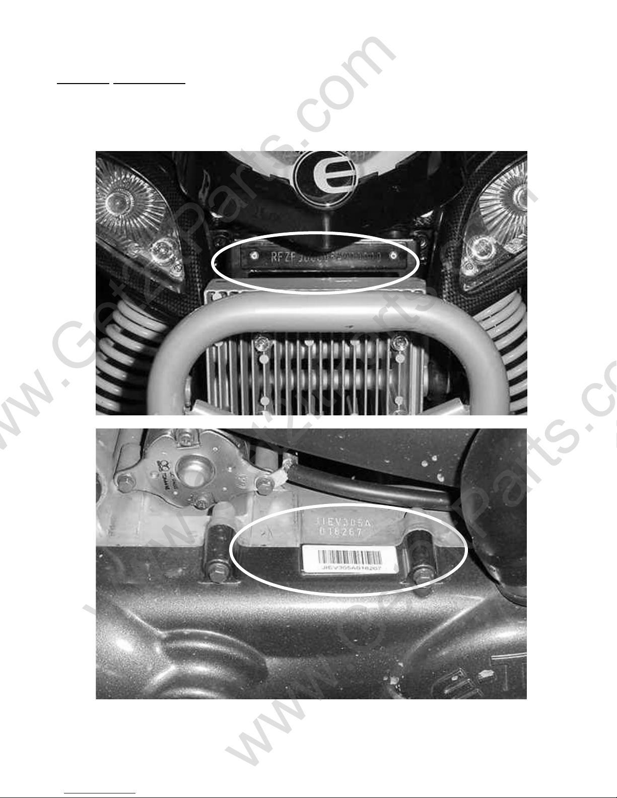
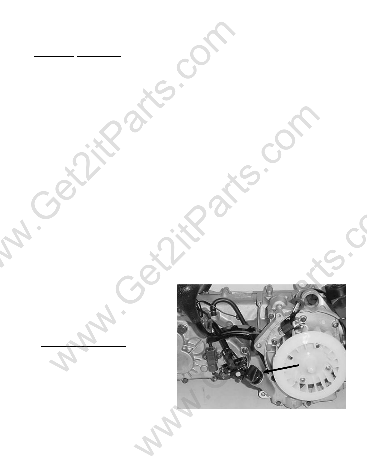
1.4 SERIAL NUMBERS
The frame serial number is stamped on the front frame just above the oil cooler. The
engine number is stamped on the left side of the crankcase.
Frame Number
Engine Number
1-4
Information
A
(
www.Get2itParts.com
www.Get2itParts.com
1.5 TORQUE VALUES
STANDARD
5 mm bolt and nut 5 N-m(3.7 ft-lbs)
6 mm bolt and nut 10 N-m( 7.4 ft-lbs)
8 mm bolt and nut 22 N-m ( 16 ft-lbs)
10 mm bolt and nut 35 N-m ( 26 ft-lbs)
12 mm bolt and nut 55 N-m ( 41 ft-lbs)
ENGINE
Cylinder head nut 28 N-m(20.7 ft-lbs)
Spark plug 12 N-m (8.9 ft-lbs)
Cylinder head bolt 20 N-m (14.8 ft-lbs)
lternator bolt 8 N-m (5.9 ft-lbs)
FRAME
Handlebar upper holder bolt 24 N-m( 17.7 ft-lbs)
Throttle housing cover screw 4 N-m ( 2.9 ft-lbs)
Steering shaft nut 50 N-m( 36.9 ft-lbs)
Steering shaft holder bolt 33 N-m ( 24 ft-lbs)
Wheel rim bolt 18 N-m ( 13.3 ft-lbs)
Tie rod lock nut 35 N-m ( 25.8 ft-lbs)
King pin nut 40 N-m ( 29 ft-lbs)
Handlebar lower holder nut 40 N-m ( 29.5 ft-lbs)
Front wheel bolt 24 N-m ( 17.7 ft-lbs)
Front axle nut 60 N-m ( 44 ft-lbs)
Front brake arm nut 4 N-m ( 3.0 ft-lbs)
Rear brake arm nut 7 N-m ( 5.2 ft-lbs)
Rear axle nut 60 N-m
Rear wheel bolt 24 N-m ( 17.7 ft-lbs)
Exhaust muffler mounting bolt 30 N-m ( 22.1 ft-lbs)
Engine hanger bolt 30 N-m ( 22 ft-lbs)
Rear axle holder bolt 90 N-m ( 65 ft-lbs)
Swingarm pivot nut 90 N-m ( 65 ft-lbs)
Rear shock absorber mounting nut 45 N-m ( 33 ft-lbs)
44.3 ft-lbs)
1-5
www.Get2itParts.com
www.Get2itParts.com
Maintenance
2. Maintenance
2.1 Maintenance data
2.2 Maintenance schedule
2.3 Fuel tube
2.4 Throttle operation
2.5 Throttle cable adjustment
2.6 Air cleaner
2.7 Spark plug
2.8 Idle speed
2.9 Drive chain
2.10 Brake system
2.11 Wheels and tires
2.12 Steering system
2.13 Toe-in
2.14 Gear oil
2.1 MAINTENANCE DATA
SPECIFICATION
SPARK PLUG:
Spark plug gap:
Recommended spark plugs:
Throttle lever free play:
Idle speed:
Brake lever free play:
Drive chain slack
Front/rear tire size
Front/rear tire pressure
Toe-in
TORQUE VALUES
SPARK PLUG
TIE-ROD LOCK NUT
ENGINE OIL
Viscosity :
API service classification
GEAR LUBRICATION OIL
Viscosity:
0.6-0.7 mm / 0.024 – 0.028”
NGK CR7HSA
5-10 mm / 0.2-0.4”
1600±100rpm
15-25 mm / 0.6-1.0”
10-25 mm / 0.4-1.0”
20*7-8 / 22*10-8
2.2± 0.3 psi (0.15 kgf/cm2)
5±10 mm / 0.2±0.4”
12-19 N-m / 9-14 ft-lbs
35-43 N-m / 26-32 ft-lbs
SAE 40 (10W-40)
SF or SG
SAE 90 (80/90 weight gear oil)
2-1
WP-0027
www.Get2itParts.com
www.Get2itParts.com
Maintenance Schedule
Four Stroke Vehicles
Scheduled
Maintenance
1 Aircleanerelement
2 Aircleaner
3 Oilfilter(Screen)
4 Engineoil
5 Tire,pressure
6 Battery
7 Sparkplug
8 Carburetor(idlespeed)
9 Steeringbearingandhandles
Checktransmissionforleak‐
10
age
11 Checkcrankcaseforleakage
12 Transmissionoil
13 Drivebelt/roller
14 Fueltankswitchandlines
Throttlevalveoperationand
15
cable
16 Engineboltsandnuts
Cylinderhead,cylinder,and
17
piston
Exhaustsystem/cleaning
18
carbon
19 CamChain/ignitiontime
20 Valveclearance
21 Shockabsorbers
22 Front/Rearsuspension
23 Main/Sidestands
24 Crankcase(PCV)Valve
Brakemechanism/brakelin‐
25
ing(pad)
300KM Every1000KM Every3000KM Every6000KM Every12000KM
200Miles 600Miles 2000Miles 3700Miles 7500Miles
NEW 1Month 3Months 6Months 1Year
I* C* R(paper) R(sponge)
I
C C
Change I Change
I I
I I
I I R
I I
I I
I I
I I
Change Change
I R
I I
I I
I I
I
I
I I
I I I I I
I I
I I
I I/L
I I
I I
TightenallBolts/Nuts&Fas‐
26
teners
Code:
I=Inspection,clean,andadjust
R=Replace
C=Clean(replacedifnecessary)
L=Lubricate
I I
*=Cleanorreplacetheaircleanerelementmoreoftenwhenthevehicleisoperatedondusty
roadsorinaheavilypollutedenvironment.
#=Maintenanceshouldbeperformedmoreoftenifthevehicleisfrequentlyoperatedathigh
speedforprolongedtimeandafterthevehiclehasaccumulated50,000miles.
www.Get2itParts.com
www.Get2itParts.com
Maintenance
2.2 MAINTENANCE SCHEDULE
The maintenance intervals in the follow table are based upon average riding conditions. Riding in
unusually dusty areas requires more frequent servicing. E-TON recommends that all maintenance
and inspections be performed ONLY by a qualified and fully trained technician.
(First Week)_________ (30 Operating days) _____ (Once each Year)
FUEL LINE X X
THROTTLE OPERATION X X
AIR CLEANER C
SPARK PLUG X
CARBURETOR IDLE SPEED X X
DRIVE CHAIN X,L X,L
BRAKE SHOE WEAR X
BRAKE SYSTEM X X
NUT, BOLT, FASTENER X X
WH EEL/TIRES X X
STEERING SYSTEM X
SUSPENSION SYSTEM X
GEAR OIL R
ENGINE OIL R X R
ENGINE OIL FILTER C C
Initial Service Regular Service Yearly Service
Note - X: Inspect and Clean, Adjust, Lubricate or Replace, if necessary
C: Clean
L: Lubricate
R: Replace
2.3 FUEL TUBE
Inspect the fuel lines for deterioration,
damage, or leaks, and replace if
necessary.
ETON 150cc models are equipped with
a vacuum fuel valve. Fuel is
transferred into the carburetor when a
vacuum is created from the engine.
Fuel should not flow if engine is not
running or if vacuum is not applied.
2-2
Vacuum
control line

Maintenance
www.Get2itParts.com
www.Get2itParts.com
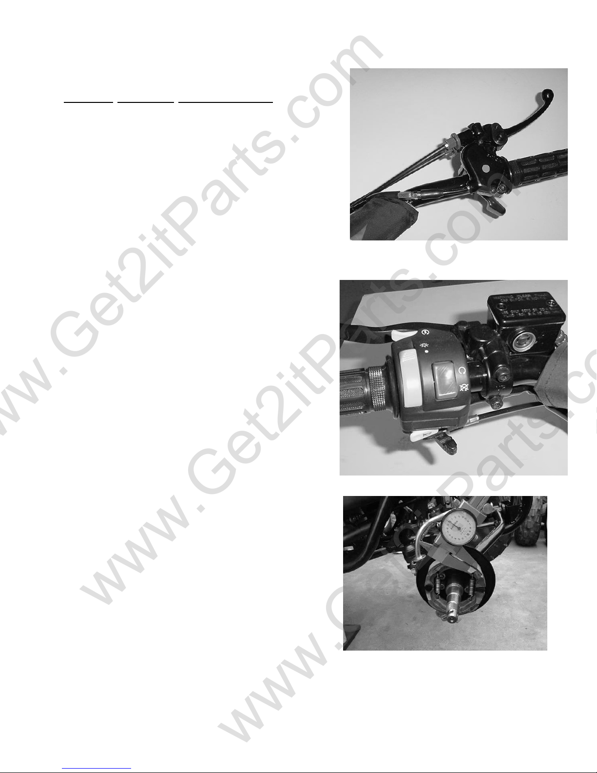
2.4 THROTTLE OPERATION
Inspect for smooth lever operation, full opening, and automatic
full closing in all steering positions.
Inspect for deterioration, damage, cuts and nicks, or kink in
the throttle cable, replace it if necessary.
Check the throttle lever; free play should be no more than
5-10 mm / 0.2-0.4” at the tip of the throttle lever.
Disconnect the throttle cable at the upper end. Lubricate the
cable with commercially lubricant to prevent premature wear.
2.5 THROTTLE CABLE ADJUSTMENT
Slide the rubber cap of the adjuster off the throttle
housing, loosen the lock nut, and adjust the free
play of the throttle lever by turning the adjuster on
the throttle housing. Inspect the free play of the
throttle lever.
Throttle cable adjuster
2-3
Maintenance
www.Get2itParts.com
www.Get2itParts.com
2.6 AIR CLEANER MAINTENANCE
(1) Loosen the screws and remove the air cleaner from carburetor.
(2) Disassemble the air cleaner cover and body.
(3) Clean the air cleaner element and screen. (See Figure below)
(4) Wash the element in non-flammable or high
flash point solvent squeeze out the solvent thoroughly and allow it to dry.
(5) Soak the element in gear oil (SAE 80-90) and
squeeze out the excess.
(6) Install the air cleaner element and screen in
the body.
(7) Assemble the air cleaner body and cover and
attach to the carburetor with the screw.
2-4
Maintenance
www.Get2itParts.com
www.Get2itParts.com
2.7 SPARK PLUG
The spark plug is located at the front of the engine.
(1) Disconnect the spark plug cap and remove the
spark plug.
(2) Visually inspect the spark plug electrodes for
wear or cracks in insulator. Replace if
needed.
(3) The center electrode should have square edges
and the side electrode should have a
constant thickness.
(4) Discard the spark plug if there is apparent wear
or if the insulator is cracked or chipped.
(5) Measure the gap with a wire-type feeler gauge and
adjust if necessary by carefully bending the
side electrode.
SPARK PLUG GAP : 0.6-0.7 mm
Recommended replacement plug: NGK CR7HSA
(6) Check the sealing washer and replace with a new
one if damaged.
(7) With the sealing washer attached thread the spark
plug in by hand to prevent cross threading.
Tighten the spark plug.
TORQUE : 12-19 N-m / 9-14 ft-lbs
2.8 IDLE SPEED SETTING
(1) Inspect and adjust the idle speed after all other
engine maintenance has been performed and is within
specifications. The engine must be warm for accurate
idle speed inspection and adjustment.
(2) Warm up the engine for about ten minutes and
connect a tachometer.
(3) Turn the throttle stop screw as required to obtain
the specified idle speed.
IDLE SPEED : 1700 ± 100 rpm
2-5
Maintenance
www.Get2itParts.com
www.Get2itParts.com
2.9 DRIVE CHAIN ADJUSTMENT
Stop the ATV and shift transmission into
neutral. Inspect the chain slack midway
between the sprockets. The standard is
10-25mm (5/8 – 1”).
If needed, remove the chain protective
cover and adjust the chain slack.
Loosen the axle holder lock nuts then
adjust the drive chain slack by turning the
adjusting nut. Tighten the axle holder lock
nuts.
Torque = 90N-m (65 ft-lbs)
When the drive chain becomes very dirty, it
should be removed, cleaned, and lubricated with
commercially available lubricant.
Clean the drive chain with kerosene and wipe it
dry.
Inspect the drive chain for possible wear or
damage.
Replace the chain if it is worn excessively or
damaged.
Inspect the sprocket teeth; if there is
excessive wear or damage, replace.
Use a commercial chain lubricant to lubricate the
drive chain; replace and adjust the slack as
described above.
2-6
Maintenance
www.Get2itParts.com
www.Get2itParts.com
2.10 BRAKE SYSTEM ADJUSTMENT
Inspect the front brake lever and cable for excessive play
or damage.
Replace or repair if necessary.
Measure the free play of the brake lever at the end of the
lever. The standard is 15-25 mm / 0.59-0.98”.
Adjust the free play of the front brake lever by turning the
adjuster on the brake lever assembly.
Inspect the rear brake lever and cable for excessive play or
damage.
Replace or repair if necessary.
Measure the free play of the brake lever at the end of the
lever.
The standard is 10-20 mm / 0.39-0.78”.
Adjust the free play of the rear brake lever by turning the
adjuster on the rear axle.
BRAKE SHOE WEAR
Front Brake
Loosen the front brake cable and inspect the brake lining
thickness.
Service Limit: 2.0mm (0.08”)
If either lining is worn beyond the service limit, replace both
brakes shoes.
Rear Brake
Replace the brake shoes if there is uneven wear or if the
lining is worn beyond the service limit.
2-7
Maintenance
www.Get2itParts.com
www.Get2itParts.com
2.11 WHEELS AND TIRES
Inspect the tire surfaces for cuts or sharp
objects.
Check the tire pressure at cold tire conditions.
The standard tire pressure is 2.2±0.3 psi (0.15
kgf/cm
2.12 STEERING SYSTEM
Check the free play of the steering shaft with the
front wheels turned straight ahead. If there is
excessive play, inspect the tie-rod, kingpin bushing,
and ball joint.
2
).
Steering Shaft Holder Bushing
Remove the front fender.
Remove the steering shaft holder and check the
steering shaft bushing for wears or damage.
If the bushing is worn or damaged, replace.
Grease the steering shaft bushing and install the
parts in the reverse order of removal.
Torque steering shaft holder bolt: 33 N-m (24 ft-lbs)
2-8
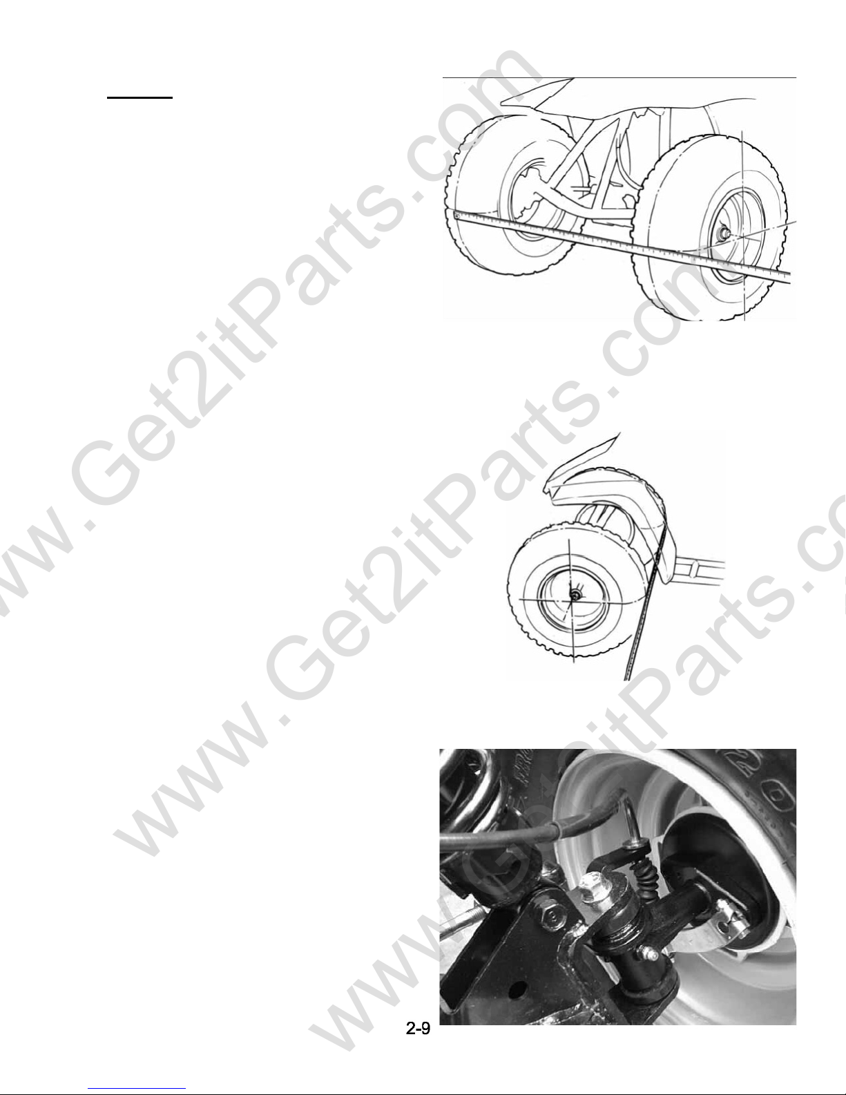
2.13 TOE-IN
www.Get2itParts.com
www.Get2itParts.com
Park the vehicle on level ground with the front
wheels facing straight ahead.
Mark the centers of the tires to indicate the axle
center height.
Measure the distance between the marks.
Carefully moving the vehicle backward, let the
wheels turn 180° so the marks on the tires are
aligned with the axle center height.
Maintenance
Measure the distance between the marks.
Calculate the difference in the front and rear
measurements.
Toe-in: 5±10mm / 0.2±0.4”
If the toe-in is out of standard, adjust it by
changing the length of the tie-rods equally by
turning the tie-rod while holding the ball joint.
Tighten the lock nuts.
Torque: 35-43 N-m / 26-32 ft-lbs
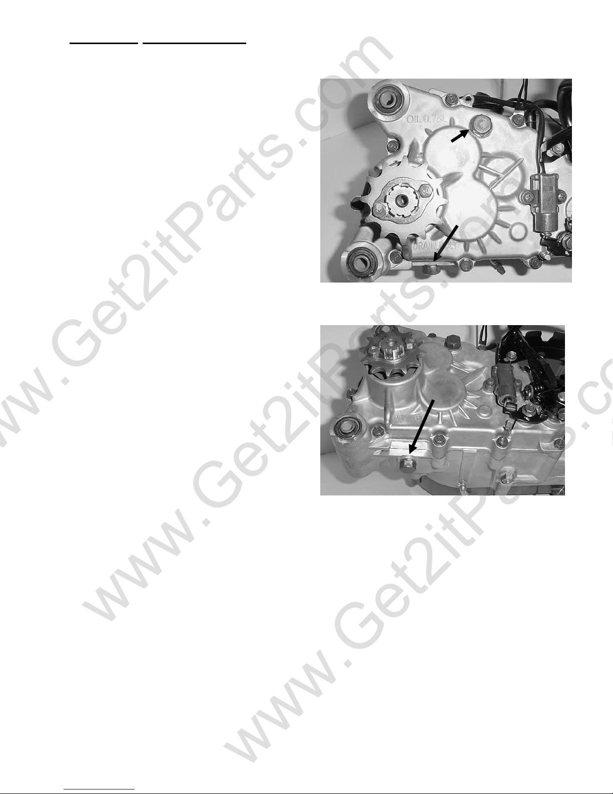
2.14 GEAR OIL MAINTENANCE
www.Get2itParts.com
www.Get2itParts.com
Maintenance
Gear oil needs to be changed every year.
There is a gear oil drain hole bolt at the rear of
engine.
(STEP 1)
Unscrew this drain hole bolt and let the dirty oil
flow out; catch the oil in a proper container for
later disposal.
Oil Fill Plug
Drain bolt
(STEP 2)
Reinsert the drain hole bolt and tighten.
(STEP 3)
Fill with 26oz of 80/90 weight gear oil through
the oil fill hole located on the engine case
beside the gear box.
NOTE: for best results, change the oil while the
engine is warm.
2-10
www.Get2itParts.com
www.Get2itParts.com
ENGINE REMOVAL AND REPLACEMENT
3.1 ENGINE
ENGINE SHOULD ONLY BE REMOVED IN THE CONDITIONS OF NECESSARY REPAIRS OR
ADJUSTMENT TO THE TRANSMISSION AND COMBUSTION SYSTEM!
3.2 ENGINE REMOVAL
Remove the seat, front and rear fender.
(See Chapter 10 )
Remove the footrest.
Remove the spark plug cap from the spark plug.
Remove the exhaust muffler.
Disconnect the carburetor cable by unscrewing
the two screws on top of the carburetor.
Disconnect the carburetor auto-choke (if
equipped), starter motor, generator, the neutral
safety switch, CDI box, and the ignition coil wire.
Remove the drive chain cover.
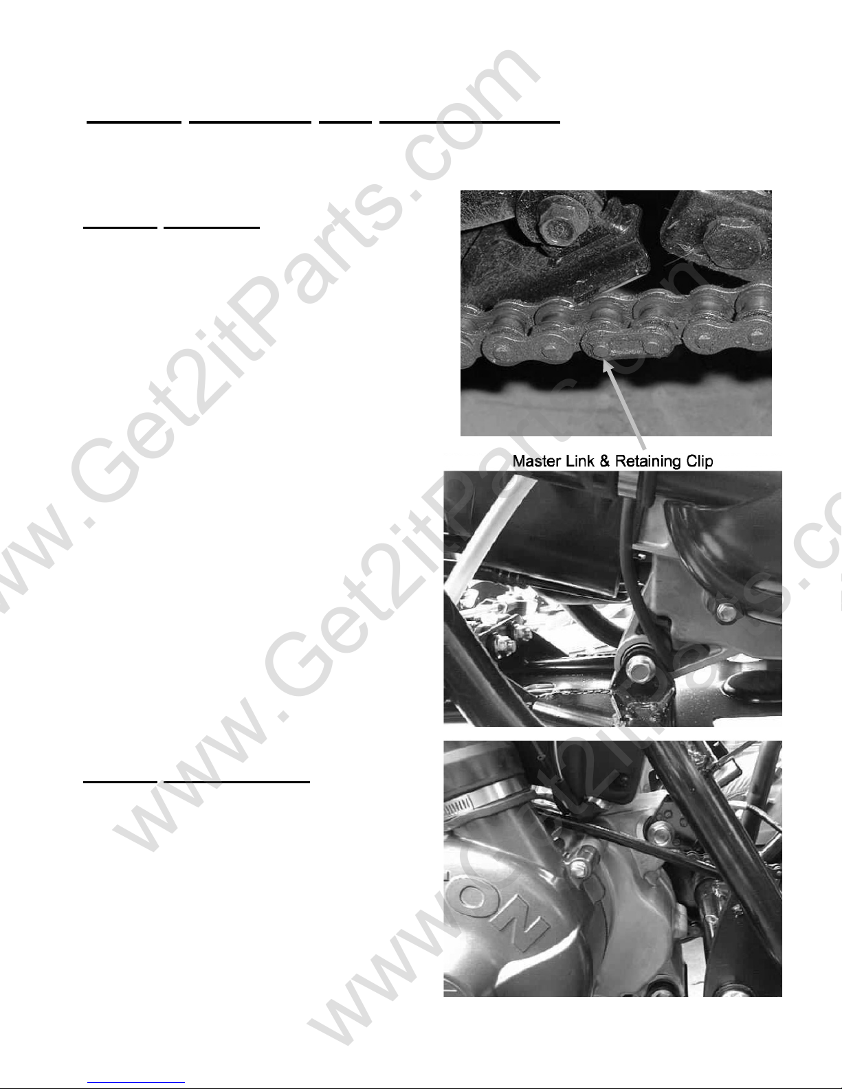
Remove the drive chain retaining clip and master
link, and remove the drive chain.
Remove the engine hanger bolts under the engine.
REMOVAL AND INSTALLATION
Remove the engine and air cleaner together
3.2 ENGINE REPLACEMENT
Engine installation is essentially the reverse order
of removal.
The torque of the engine hanger bolt is 30 N-m / 22
ft-lbs.
Route the wires and cable properly in reverse
order of removal.
3-1
www.Get2itParts.com
www.Get2itParts.com
LUBRICATION
4. Lubrication
4.1 Service Information
4.2 Trouble Shooting
4.3 Engine Oil Level
4.4 Engine Oil & Filter Change
4.5 Oil Pump Removal / Installation
4.1 SERVICE INFORMATION
GENERAL
1. This section describes cylinder head, valves, camshaft, and other parts maintenance.
2. The engine must be removed from the frame to service the cylinder head.
3. Camshaft lubrication oil is fed to the cylinder head through an oil hole in the engine case.
4. Before installing the cylinder head, be sure the hole is not clogged and the gasket, O-ring,
and dowel pins are in place
SPECIFICATIONS
ITEM STANDARD SERVICE LIMIT
Cylinder compression
Cam lobe height IN
EX
Rocker arm I.D.
Rocker arm shaft O.D.
Cylinder head warp
Valve spring free length IN
EX
Valve stem O.D. IN
EX
Valve guide I.D. IN/EX
Stem-to-guide clearance IN
EX
Valve seat width IN
EX
TORQUE VALUES
Cylinder head bolts
Camshaft holder flange nuts
Tappet adjusting nut
Oil Drain Bolt
12±0.5 kg/cm2 --------
29.795mm / 1.180” 29.395mm / 1.157”
29.560mm / 1.16” 29.160mm / 1.148”
10.000-10.018mm / 0.394” 10.10mm / 0.398”
9.972-9.987mm / 0.393 “ 9.91mm / 0.390”
-------- 0.05mm
32.3mm / 1.27” 31.2mm / 1.23”
35.0mm / 1.38” 34.1mm / 1.34”
4.975-4.990mm / 0.196” 4.90mm / 0.193”
4.955-4.970mm / 0.195” 4.90mm / 0.193”
5.000-5.012mm / 0.197” 5.30mm / 0.209”
0.010-0.037mm 0.08mm
0.030-0.057mm 0.10mm
1.0mm 1.80mm
1.0mm 1.80mm
8 - 12 N-m (6-9 ft-lbs)
20 - 24 N-m (15-18 ft-lbs)
9 - 12 N-m (7-9 ft-lbs)
20-30 N-m (15-22 ft-lbs)
4-1
www.Get2itParts.com
www.Get2itParts.com
LUBRICATION
4.2 TROUBLE SHOOTING
Engine top-end problems often affect engine performance. These problems can be diagnosed by a
compression test, or by tracing engine noise to the top end with a sounding rod or stethoscope.
Low compression (Valve)
-Incorrect valve adjustment.
-Worn or damaged valve seats.
-Burned or bent valve.
-Incorrect valve timing.
-Weak valve spring.
Cylinder head
-Leaking or damaged head gasket.
-Warped or cracked cylinder head.
-Faulty cylinder or piston.
Excessive noise
-Incorrect valve adjustment.
-Sticking valve or broken valve spring.
-Worn or damaged rocker arm or camshaft.
-Worn or damaged cam chain.
-Worn or damaged cam chain tensioner.
-Worn cam sprocket teeth.
Excessive smoke
-Damaged valve stem seal.
-Faulty cylinder or piston rings.
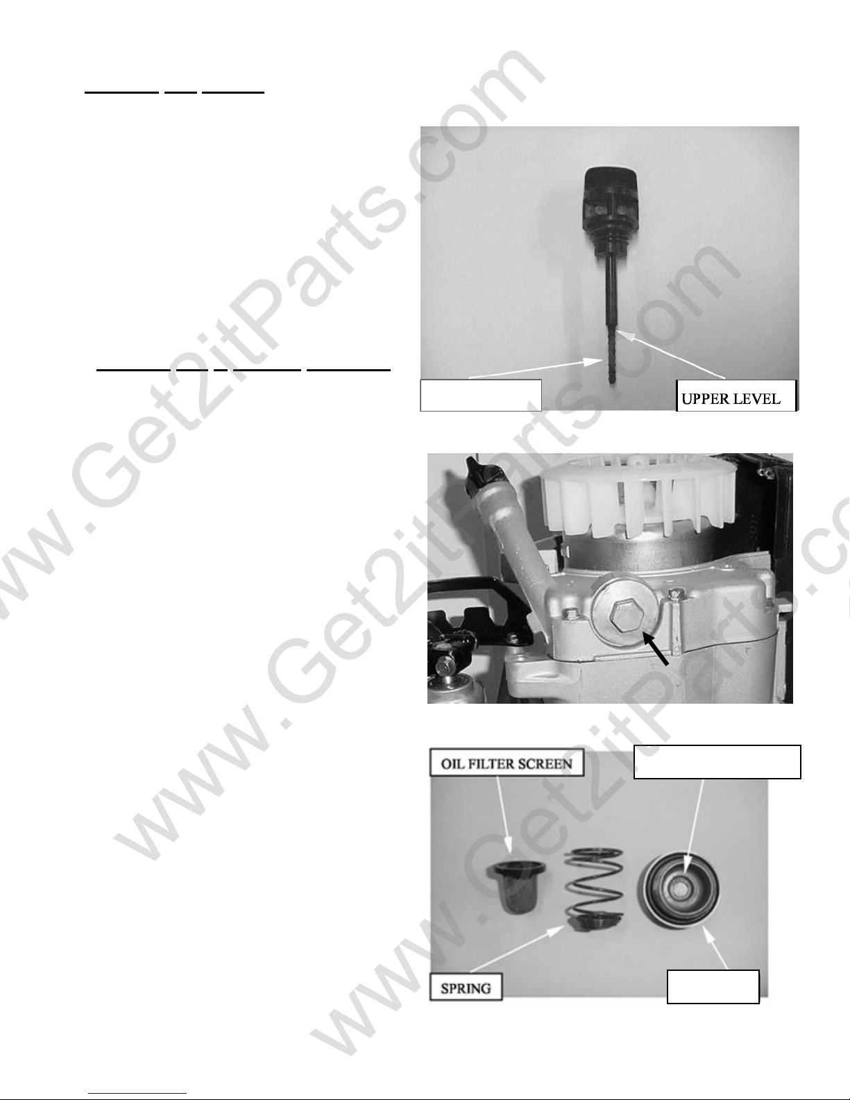
4.3 ENGINE OIL LEVEL
Place the engine on the level plane.
Check the oil level with the oil level
dipstick, but do not screw it in when
making this check.
4.3.1 TROUBLESHOOTING
Oil level too low-high oil consumption
-Typical oil consumption.
-External oil leaks.
-Oil not changed often enough.
-Worn piston rings.
Oil contamination
-Worn piston rings.
-Oil or filter not changed often enough.
4-2
Engine
Oil
Dipstick
LUBRICATION
www.Get2itParts.com
www.Get2itParts.com
4.3 ENGINE OIL LEVEL (continued)
Add the recommended oil up to the upper
level if the oil level is below or near lower level
line on the gauge.
4.4 ENGINE
Remove the oil drain plug.
NOTE: Drain the oil while the engine is warm to
ensure complete draining.
Remove the oil drain plug, spring, and oil filter
screen.
Check the O-ring for damage or wear.
Install a new oil filter screen and spring; then,
install the plug.
OIL & FILTER CHANGE
LOWER LEVEL
Oil drain plug
OIL DRAIN PLUG
O-RING
4-3
www.Get2itParts.com
www.Get2itParts.com
4.4 ENGINE OIL & FILTER CHANGE
(continued)
Install the oil drain bolt with sealing washer.
TORQUE: 20-30 N-m (15-22 ft-lbs)
Fill the crankcase with the SAE 10w40 oil.
OIL CAPACITY: 0.8 liter / 0.2 gal at draining.
Install the oil drain plug.
Install the oil level gauge.
Start the engine and let it idle for 2 - 3 minutes.
Stop the engine and check that the oil level is
at the upper line on the gauge. Make sure there
are no oil leaks.
Oil drain plug
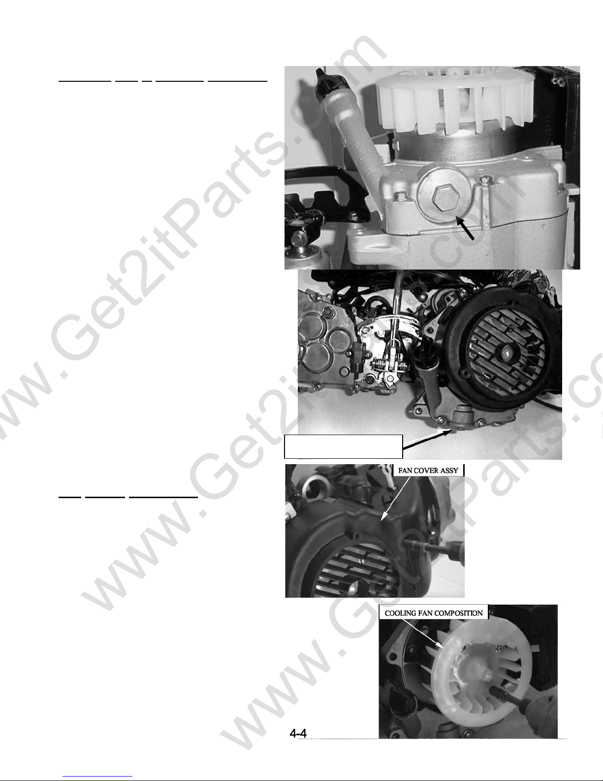
4.5 OIL PUMP REMOVAL
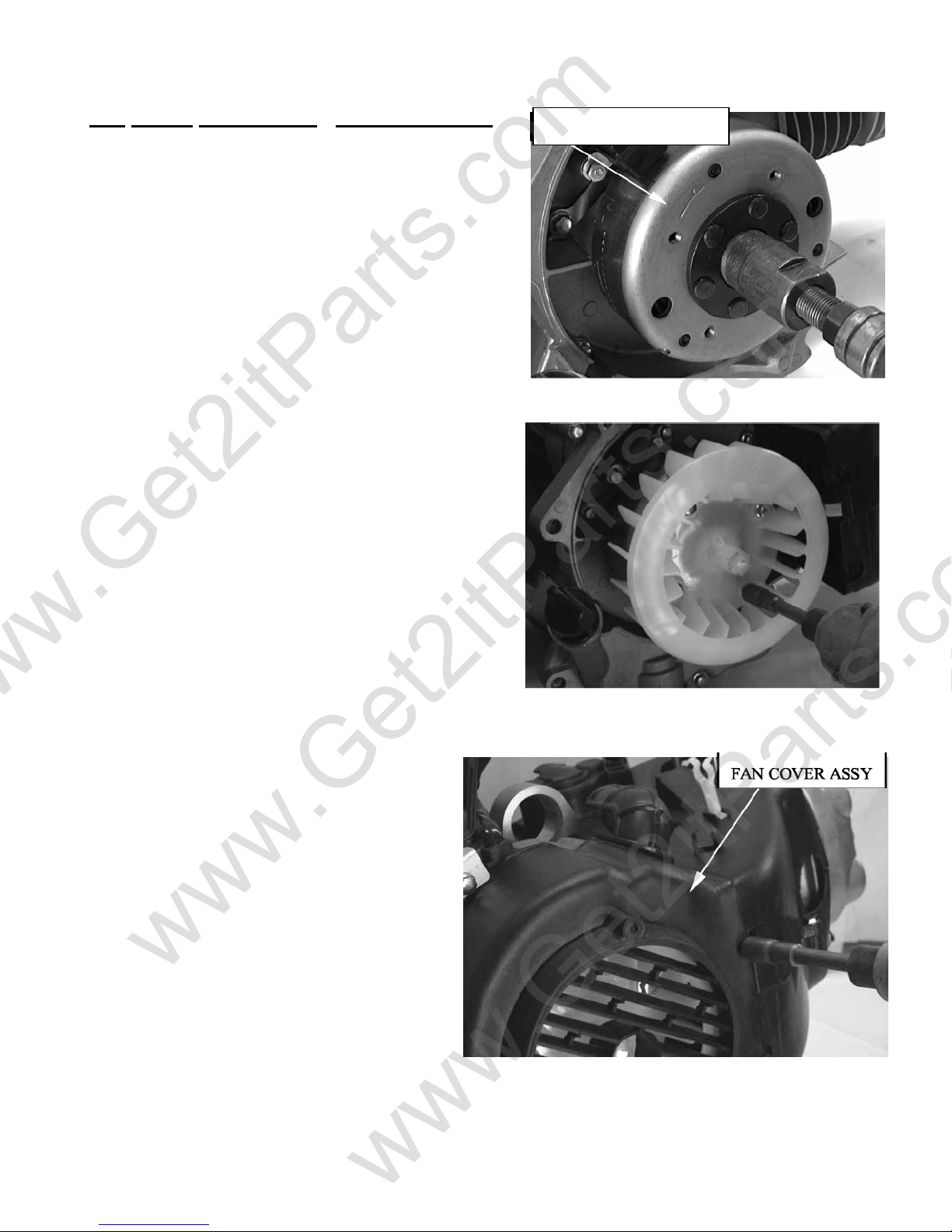
Remove the fan cover assembly.
Remove the cooling fan assembly.
OIL DRAIN PLUG
4-21
www.Get2itParts.com
www.Get2itParts.com
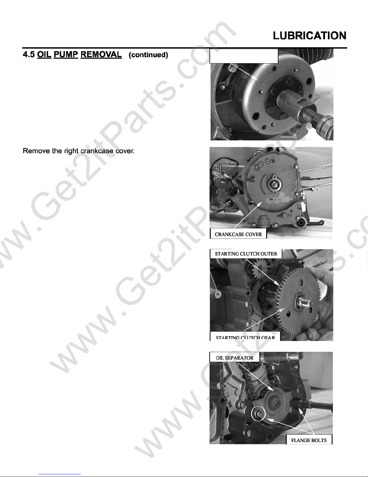
FLYWHEEL
Remove the flywheel and the AC Generator
assembly. Flywheel pullers are available
from the ETON Parts Department.
Remove the starting clutch outer and gear
assembly.
Remove the flange bolts and oil separator.
4-5
www.Get2itParts.com
www.Get2itParts.com
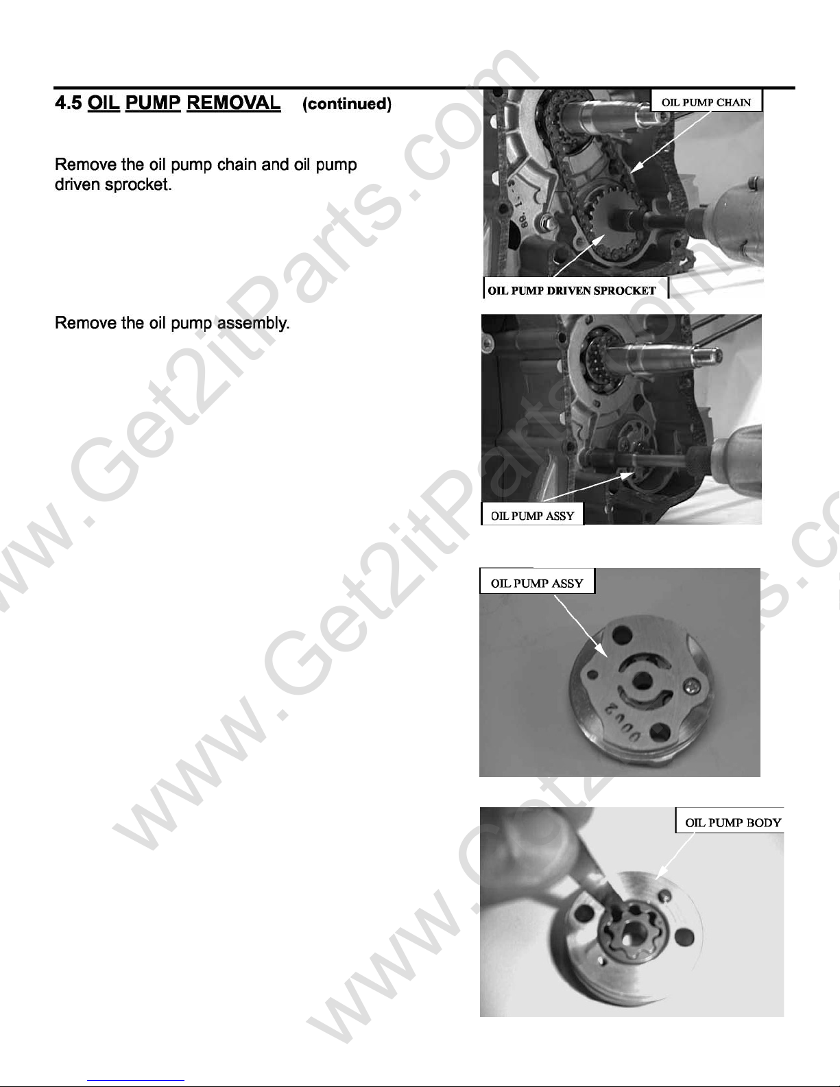
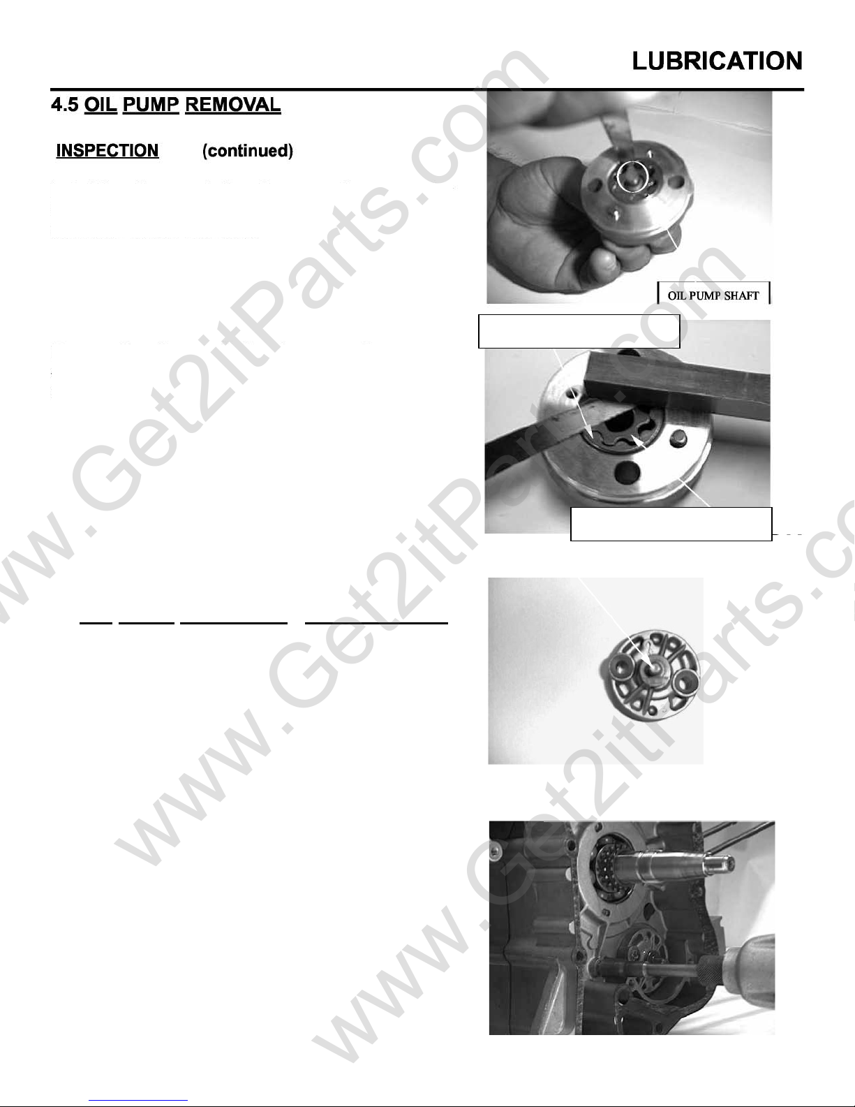
Disassemble the oil pump.
INSPECTION
Measure the oil pump rotor-to-body clearance.
SERVICE LIMIT: 0.12 mm / 0.005”
4-6
www.Get2itParts.com
www.Get2itParts.com
Install the oil pump shaft and measure the pump rotor
tip clearance.
Remove the oil pump shaft and measure the pump
end clearance.
SERVICE LIMIT: 0.2 mm / 0.008”
OIL PUMP OUTER ROTOR
4.5 OIL PUMP ASSEMBLY / INSTALLATION
Install the outer rotor, inner rotor and oil pump shaft
onto the body.
NOTE: Pour a drop of clean engine oil inside
the oil pump.
Install the oil pump assembly.
OIL PUMP INNER ROTOR
4-7
www.Get2itParts.com
www.Get2itParts.com
4.5 OIL PUMP ASSEMBLY / INSTALLATION
(continued)
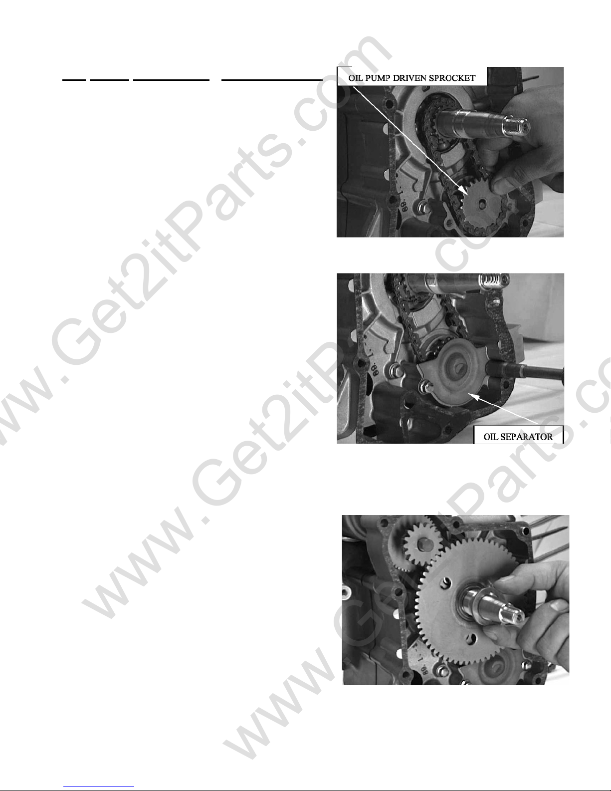
Install the oil pump driven sprocket and oil pump
chain.
Install the oil separator.
LUBRICATION
Install the starting clutch outer and gear assembly.
Install the new gasket, dowel pins, and right crankcase
cover.
4-8
www.Get2itParts.com
www.Get2itParts.com
LUBRICATION
4.5 OIL PUMP ASSEMBLY / INSTALLATION
(continued)
Install the AC Generator and then the outer flywheel.
Install the cooling fan.
FLYWHEEL
Install fan housing cover.
4-9
www.Get2itParts.com
www.Get2itParts.com
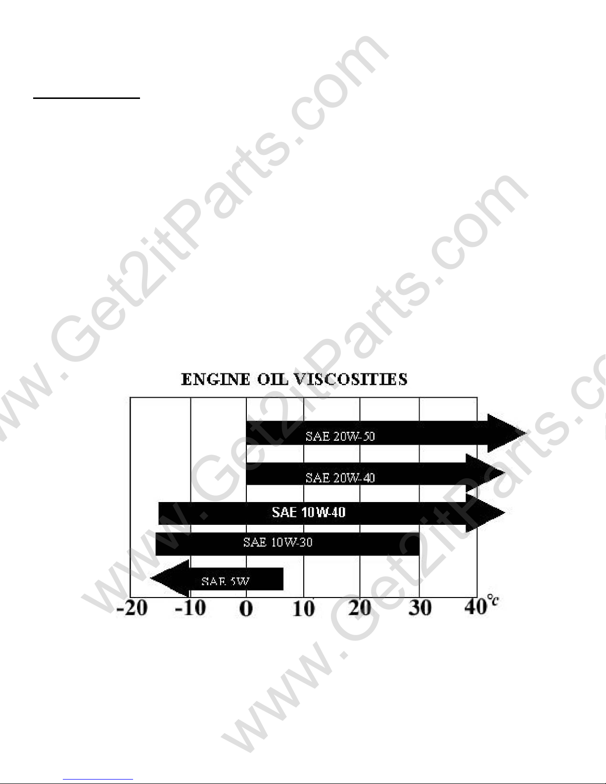
4.6 ENGINE OIL
This section describes inspection and replacement of the engine oil, oil filter screen, and
assembly of the oil pump.
Fill the oil pump with clean oil when reassembling the pump.
SPECIFICATION
ENGINE OIL CAPACITY 0.8-1.0 liter / 0.2-0.3 gal
API service classification: SF or SG Viscosity: SAE 20w-40
When the average temperature in your riding area is within the indicated range,
you should use the other engine oil viscosity that's shown in the chart.
LUBRICATION
4-10
www.Get2itParts.com
www.Get2itParts.com
CYLINDER HEAD / VALVES
5. CYLINDER
5.1 SERVICE INFORMATION
5.2 TROUBLESHOOTING
5.3 CAMSHAFT ASSEMBLY REMOVAL
5.4 CYLINDER HEAD REMOVAL
5.5 CYLINDER HEAD INSTALLATION
5.1 SERVICE INFORMATION
GENERAL
This section describes the maintenance of cylinder head, valves, camshaft, and the other parts.
The engine must be removed from the frame to service the cylinder head.
Camshaft lubrication oil is fed to the cylinder head through an oil hole in the engine case. Before
installing the cylinder head, be sure the hole is not clogged and the gasket, O-ring, and dowel
pins are in place.
SPECIFICATIONS
HEAD / VALVES
Cylinder I.D. 57.400 - 57.410mm / ~2.260” 57.50mm / 2.263”
Piston PISTON O.D. 57.3075 - 57.3095mm / ~2.256” 56.5mm / 2.22”
Piston pin PISTON PIN BORE 15.002 - 15.008mm / ~0.0510” 15.04mm / 0.592”
Piston rings PISTON PIN O.D. 14.994 – 15.000mm / ~0.590” 14.960mm / 0.589””
CYLINDER-TO-PISTON CLEARANCE
CONNECTING ROD SMALL END I.D. 15.010 – 15.028mm / ~0.591” 15.06mm / 0.593”
TORQUE VALUES
Cylinder head bolts
Camshaft holder flange nuts
Tapper adjusting nut
TAPER ------------ 0.10mm / 0.004”
OUT OF ROUND ------------ 0.10mm / 0.004”
WARPAGE ACROSS TOP ------------ 0.10mm / 0.004”
PISTON-TO-PIN CLEARANCE
PISTON-TO-PIN CLEARANCE TOP 0.015 – 0.050mm/0.0006-0.002” 0.12mm/0.005”
PISTON RING-TO-RING SECOND 0.015 – 0.050mm/0.0006-0.002” 0.12mm0.005”
GROOVE CLEARANCE TOP/SEC 0.10 – 0.25mm/0.004-0.01” 0.5mm/0.02”
PISTON RING END GAP OIL 0.2 –0.7mm/0.008-0.03” -----------
ITEM STANDARD SERVICE LIMIT
0.002 – 0.014mm/7.8x10-5-0.0006”
0.0005 – 0.1025mm/2.0x10-6-0.004”
20-24 N-m / 15-18 ft-lbs
0.02mm/0.0008”
0.1mm/0.004”
8-12 N-m / 6-9ft-lbs
9-12 N-m / 7-9 ft-lbs
5-1
 Loading...