

Eton America Rascal IXL-40, Viper Jr. RXL-40, Viper RXL-40E, Viper 40E, Viper 40E RXL-40E Service Manual

www.Get2itParts.com
www.Get2itParts.com
ETON America
40cc Service Manual
Covering:
Rascal IXL-40
Viper Jr. RXL-40
Viper 40E RXL-40E

www.Get2itParts.com
www.Get2itParts.com

TABLE OF CONTENTS
www.Get2itParts.com
www.Get2itParts.com
1. ATV Unit Information
2. General Maintenance Schedule
3. Engine Removal
4. Fuel System
5. Engine Combustion system
6. Pull/Electric Starter
7. Transmission
8. Front Wheels and Steering
9. Rear Wheels and Drive System
10. Body Cover & Exhaust System
11. Electrical System
12. Trouble Shooting Chart
13. RXL-40E Specific

www.Get2itParts.com
www.Get2itParts.com

1. INFORMATION
www.Get2itParts.com
www.Get2itParts.com
1.1 SAFETY
• Gasoline is extremely flammable and is explosive under certain conditions.
• Do not smoke or allow sparks or flames in your work area.
• Never run the engine in a closed area. The exhaust contains poisonous carbon monoxide gas that may
cause loss of consciousness and lead to death.
• The battery electrolyte contains sulfuric acid. Protect your eyes, skin, and clothing. In case of contact,
flush thoroughly with water. Seek medical attention if electrolyte gets in the eyes.
1.2 NOTES
All information, illustrations, directions and specifications included in this publication are based on the
latest product information available at the time of approval for printing.
ETON America, LLC reserves the right to make changes at any time without notice and
without incurring any obligation whatever.
No part of this publication may be rep roduced with out written p ermission. R evised 11/04/2004.
1-1
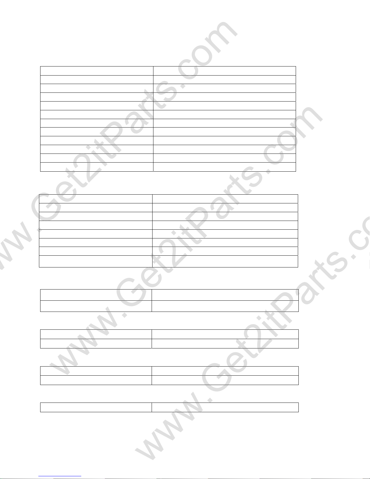
1.3 SPECIFICATIONS
www.Get2itParts.com
www.Get2itParts.com
ENGINE
Type Air-Cooled 2-Stroke
Displacement 41.5 cc
Bore and Stroke 40.0*33mm
Compression 6.6:1
Maximum Torque 2.5 N-m@5000rpm
Maximum Horsepower 2.2 Ps @7000rpm
Carburetor Mikuni VM16
Ignition Capacitor Discharge
Starting Hand Pull (Recoil) starter
Lubrication Oil/Fuel Premix
Air cleaner Dry Type
Transmission Single-speed automatic clutch
CHASSIS
Overall Length 1160mm(45.7inch)
Overall Width 650mm(25.6inch)
Overall Height 727mm(28.6inch)
Seat Height 540mm(21.3inch)
Wheel base 728mm(28.7inch)
Ground Clearance 75mm(3.0inch)
Dry Weight 60kg
Fuel Ta n k C a pa c it y 3.5liter
INFORMATION
SUSPENSION
Front Two absorber and A-arm
Rear One absorber and Swing arm
BRAKES
Front None
Rear Drum
TIRES
Front 145-70/6
Rear 145-70/6
COLOR
Color Red / Blue
*Specifications subject to change without notice.
1-2
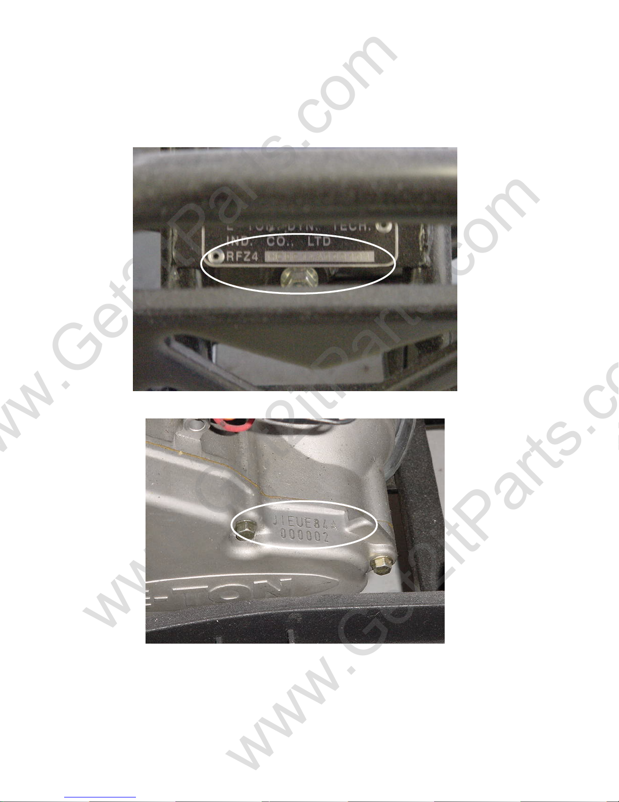
1.4 SERIAL NUMBER
www.Get2itParts.com
www.Get2itParts.com
The Vehicle Identification Number (VIN) is stamped on a plate attached to the front of the frame.
The Engine serial number is stamped on the left side of the crankcase.
Serial Number
Engine Number
1-3
INFORMATION
m
)
m
m
m
m
m
m
m
)
m
m
m
m
)
)
www.Get2itParts.com
www.Get2itParts.com
1.5 TORQUE VALUES
ENGINE
Item Qty Thread dia.(mm) Torque : N–m / (ft-lbs)
Spark plug 1 14 m
Intake pipe mounting bolt 2 5 mm 3.5-5 / (2.5 – 4)
Cylinder socket bolt 4 5 m
L Case bolt 4 5 m
AC generator assembly nut 1 8 mm 18-20 (13-15)
Clutch weight bolt 2 8 mm 18-20 (13-15)
Clutch flange nut 1 10 m
R. Case cover bolt 4 6 m
Mission case socket bolt 4 6 mm 10-14 (7-10)
Gearbox cover socket bolt 5 6 mm 10-14 (7-10)
Gearbox cover drain bolt 1 8 m
Oil drain bolt 1 8 mm 20-30 (15-22)
Cam sprocket bolt 2 6 m
L Case bolt 4 6 mm 10-14 (7-10)
12-19 / (9-14
4.5-6 (3-4.5)
4.5-6 (3-4.5)
35-45 (26-33)
10-14 (7-10)
20-30 (15-22)
10-14 (7-10)
FRAME
Item Qty Thread dia.(mm) Torque: N – m / (ft-lbs)
Handlebar upper holder bolt 4 6 m
Steering shaft nut 1 14 mm 50-60 / (37-44)
Steering shaft bushing holder nut 2 8 m
Tie rod lock nut 4 10 m
King pin nut 2 10 mm 30-40 / (22-30)
Front axle nut 2 12 m
Rear brake arm nut 1 6 mm 7-12 / (5-9)
Rear axle nut 2 14 m
Exhaust muffler mounting bolt 1 8 mm 30-35 / (22-25)
Engine hanger bolt nut 3 8 mm 30-35 / (22-25)
10-14 / (7-10
24-30 / (17-22)
35-43 (25-32)
55-65 / (41-48)
60-80 / (44-59)
STANDARD TORQUE VALUES
Item Torque N-m / (ft-lbs) Item Torque N-m / (ft-lbs)
5mm bolt nut 4.5-6 / (3-4.5
6mm bolt nut 8-12 / (6-9) 6mm screw, 6mm flange bolt 7-11 / (5-8)
8 mm bolt nut 18-25 / (13-18)
10 mm bolt nut 30-40 / (22-30) 8mm flange bolt nut 24-30 / (17-22)
12 mm bolt nut 50-60 / (37-44) 10mm flange bolt nut 35-45 / (25-33)
5mm screw 3.5-5 / (2.5-4
with 8mm head
6mm flange bolt nut
10-14 / (7-10)
1-4

2. MAINTENANCE
www.Get2itParts.com
www.Get2itParts.com
2.1 MAINTENANCE DATA
2.2 MAINTENANCE SCHEDULE
2.3 FUEL TUBE
2.4 THROTTLE OPERATION
2.5 THROTTLE CABLE ADJUSTMENT
2.6 AIR CLEANER
2.7 SPARK PLUG
2.8 IDLE SPEED
2.9 DRIVE CHAIN
2.10 BRAKE SYSTEM
2.11 WHEELS AND TIRES
MAINTENANCE
2.12 STEERING SYSTEM
2.13 TOE-IN
2.14 GEAR OIL
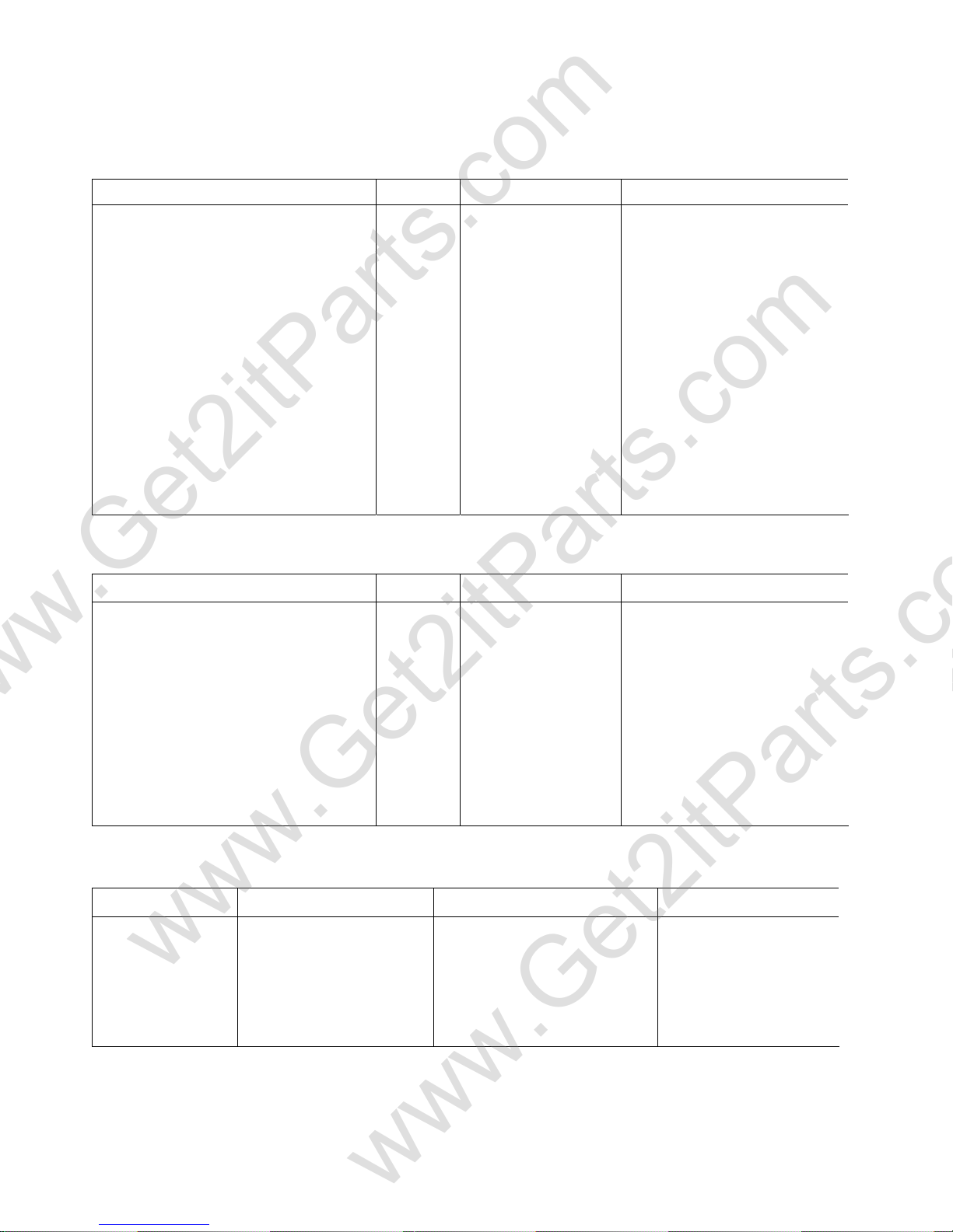
2.1 MAINTENANCE DATA
SPECIFICATIONS
SPARK PLUG GAP:
RECOMMENDED SPARK PLUGS:
THROTTLE LEVER FREE PLAY:
IDLE SPEED:
BRAKE LEVER FREE PLAY:
DRIVE CHAIN SLACK
FRONT/REAR TIRE PRESSURE
TOE-IN
0.6-0.7 mm
DR8ES-L (NGK)
5-10 mm
1700±100 rpm
15-25 mm
10-25 mm
2.2± 0.3 psi(0.15 kgf/cm2)
5±10 mm
2-1
MAINTENANCE
N
www.Get2itParts.com
www.Get2itParts.com
2.2 MAINTENANCE SCHEDULE
The maintenance intervals in the follow table are based upon average riding conditions. Riding in unusually
dusty areas requires more frequent servicing.
FUEL LINE I
THROTTLE OPERATION
AIR CLEANER
SPARK PLUG I
CARBURETOR IDLE SPEED
DRIVE CHAIN
BRAKE SHOE WEAR
BRAKE SYSTEM
UT, BOLT, FASTENER
WHEEL
STEERING SYSTEM
SUSPENSION SYSTEM I
GEAR OIL R
Note - I: Inspect and Clean, Adjust, Lubricate or Replace, if necessary
C: Clean
L: Lubricate
R: Replace
INITIAL SERVICE
(First week)
I I C
I
I,L
I
I
I
REGULAR SERVICE
(Every 30 operating days)
I
I,L
I
I
I
EVERY YEAR
I
I
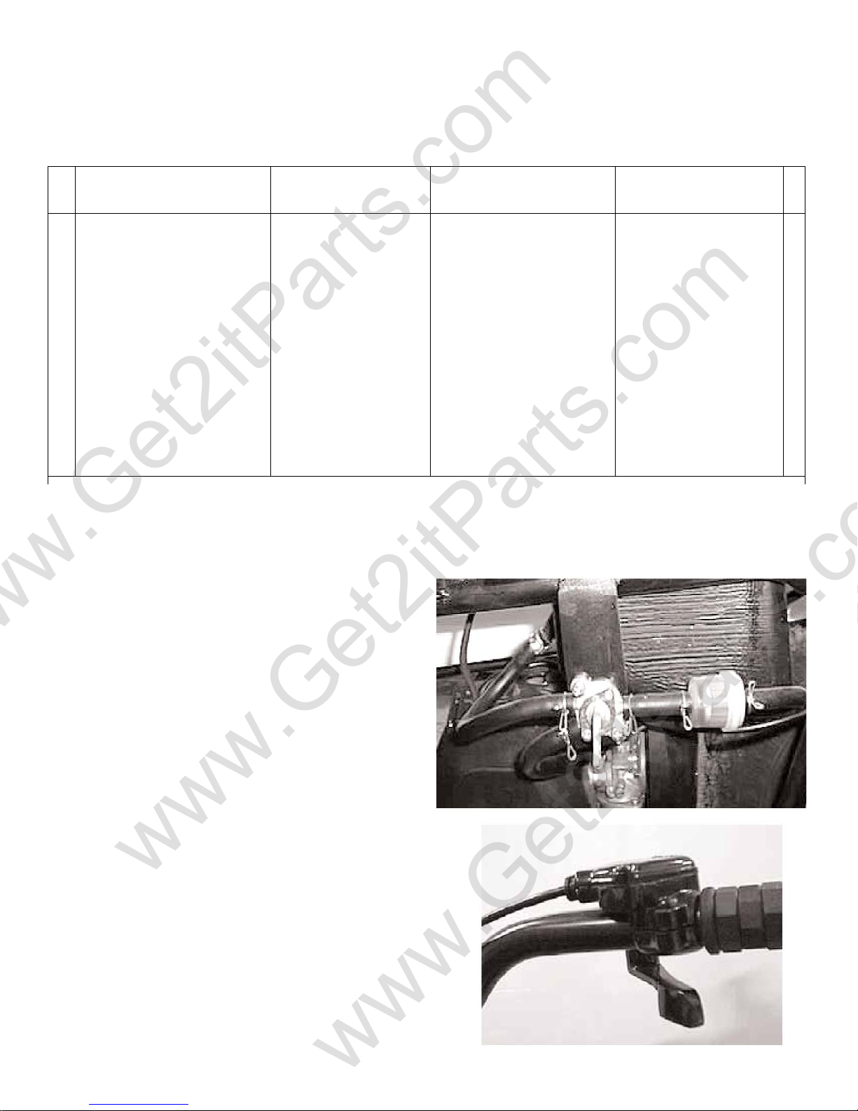
2.3 FUEL LINES
Inspect the fuel lines for deterioration, damage, or leakage
and replace if necessary.
2.4 THROTTLE OPERATION
Inspect for smooth throttle lever full opening and auto matic
full closing in all steering positions. Inspect for
deterioration, damage, or kinking in the throttle cable. If
any, replace it.
Check the throttle lever. Free play is 5-10 mm at the tip of
the throttle lever.
Disconnect the throttle cable at the upper end. Lubricate
the cable with commercially lubricant to prevent premature
wear.
2-2
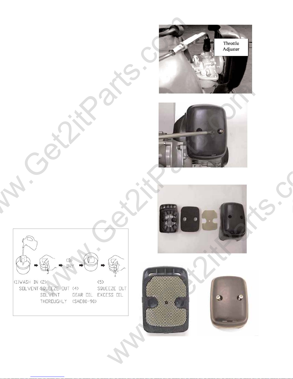
2.5 THROTTLE CABLE ADJUSTMENT
www.Get2itParts.com
www.Get2itParts.com
Slide the rubber cap of the adjuster off the throttle
housing, loosen the lock nut, and adjust the free play of
the throttle lever by turning the adjuster on the throttle
housing. Inspect the free play of the throttle lever.
2.6 AIR CLEANER
(1) Loosen the screws and remove the air cleaner from
carburetor.
(2) Disassemble the air cleaner cover and body.
(3) Remove the air cleaner element and screen.
(4) Wash the element in non-flammable or high
flash point solvent, squeeze out the solvent
thoroughly, and allow to dry completely.
(5) Soak the element in gear oil (SAE 80-90) and
squeeze out the excess oil.
(6) Install the air cleaner element and screen in the
body.
(7) Assemble the air cleaner body and cover.
MAINTENANCE
2-3
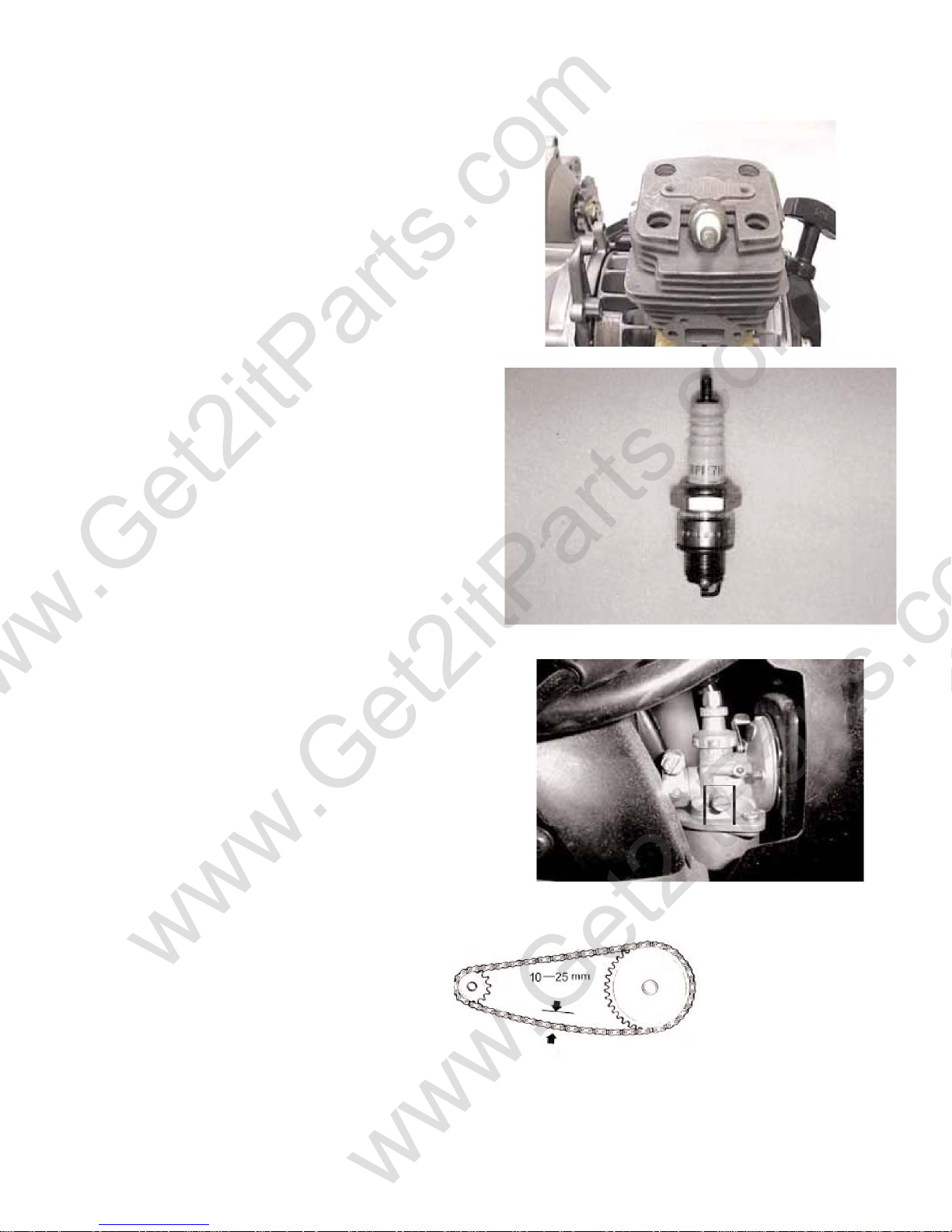
2.7 SPARK PLUG
p
www.Get2itParts.com
www.Get2itParts.com
(1) Disconnect the spark plug cap and remove the spark
plug.
(2) Visually inspect the spark plug electrodes for wear.
(3) The center electrode should have square edges and
the side electrode should have a constant thickness.
(4) Discard the spark plug if there is apparent wear
or if the insulator is cracked or chipped.
(5) Measure the gap with a wire-type feeler gauge and
adjust if necessary by carefully bending the side electrode.
SPARK PLUG GAP: 0.2-0.6 mm
REQUIRED REPLACEMENT PLUG:
BPM7A (NGK) or
BPM6Y (NGK)
(6) Check the sealing washer and replace with a new
one if damaged.
(7)
With the sealing washer attached thread the spark
lug in by hand to prevent cross threading.
Tighten the spark plug.
TORQUE: 12-19 N-m
MAINTENANCE
2.8 IDLE SPEED
(1) Inspect and adjust the idle sp eed after al l other engine
maintenance has been performed and is within
specifications. The engine must be warm for accurate idle
speed inspection and adjustment.
(2) Warm up the engine for about five minutes and
connect a tachometer.
(3) Turn the throttle stop screw as required to obtain the
specified idle speed.
IDLE SPEED: 1700 ± 100 rpm
2.9 DRIVE CHAIN
Inspect the chain slack. The standard is 10-25mm.
2-4
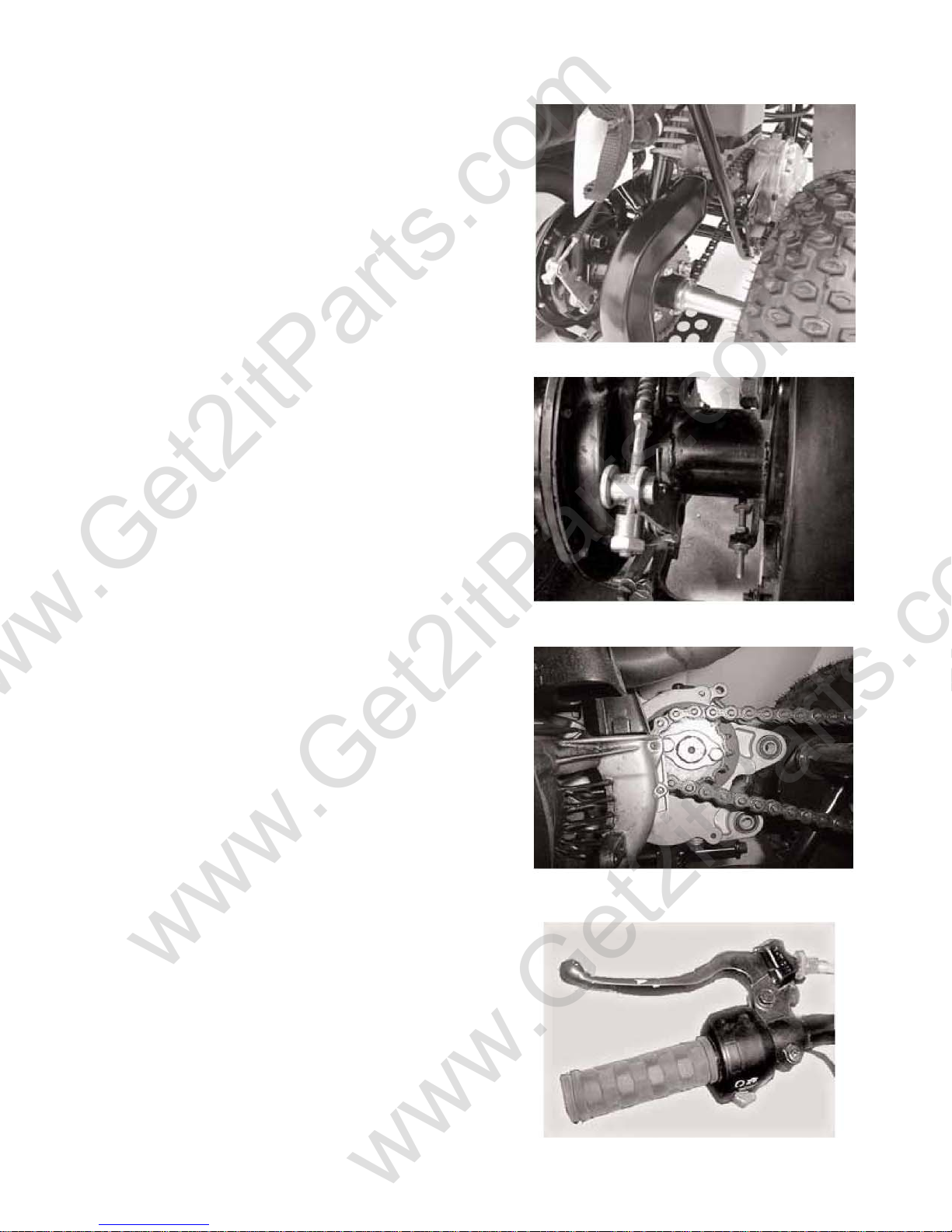
www.Get2itParts.com
www.Get2itParts.com
Remove the chain protection cover.
Adjust the chain slack.
Loosen the lock bolts (4), and then adjust the drive
chain slack by turning the adjusting nut.
Tighten the four lock bolts.
When the drive chain becomes very dirty, it should be
removed, cleaned, and lubricated with a specified lubricator.
Use commercial chain lubricant to lubricate the drive chain.
Clean the drive chain with kerosene and wipe it dry.
Inspect the drive chain for possible wear or damage.
Replace the chain if it is worn excessively or damaged.
Inspect the sprocket teeth. If it shows signs of excessive wear
or damage, replace.
MAINTENANCE
2.10 BRAKE SYSTEM
Inspect the rear brake lever and cable for excessive play
or damage.
Replace or repair if necessary.
Measure the free play of the rear brake lever at the end of
the lever. The standard is 15-25 mm.
2-5
www.Get2itParts.com
www.Get2itParts.com
Adjust the free play of the rear brake lever by turning
the adjuster on the rear axle.
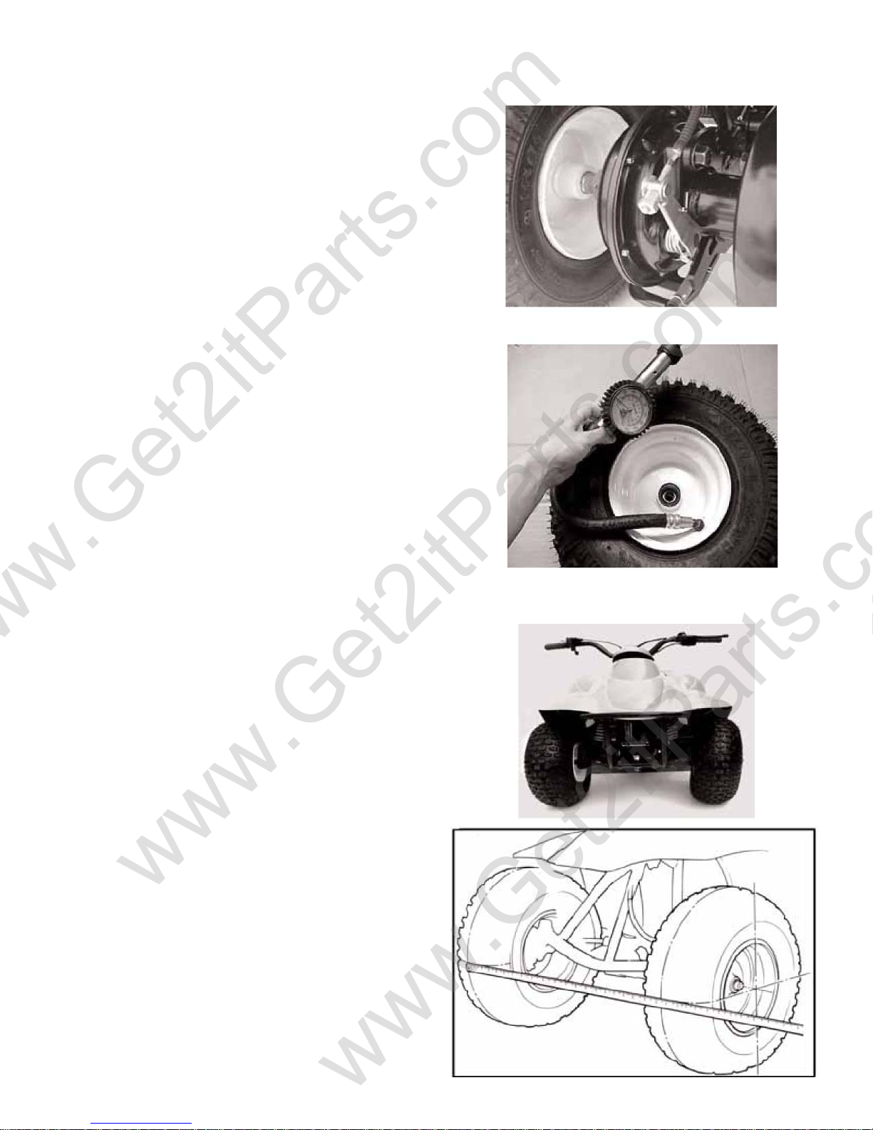
2.11 WHEELS AND TIRES
Inspect the tire surfaces for cuts, nails, or other sharp
objects. Check the tire surfaces at cold tire conditions. The
standard tire pressure is
2.2±0.4 psi. (0.15 kgf/cm2)
MAINTENANCE
2.12 STEERING SYSTEM
Check the free play of the steering shaft with the front
wheels pointed straight ahead.
If there is excessive play, inspect the tie-rod, kingpin
bushing, and ball joint.
2.13 TOE-IN
Park the vehicle on level ground with the front wheels
facing straight ahead.
Mark the centers of the tires to indicate the axle center
height.
Measure the distance between the marks.
2-6
Carefully moving the vehicle back, let the wheels turn
www.Get2itParts.com
www.Get2itParts.com
180° so the marks on the tires are aligned with the axle
center height.
Measure the distance between the marks.
Calculate the difference in the front and rear measurements.
Toe-in: 5±10mm
If the toe-in is out of standard, adjust it by changing the
length of the tie-rods equally by turning the tie-rod while
holding the ball joint.
Tighten the lock nuts.
Torque: 35-43 N/m
MAINTENANCE
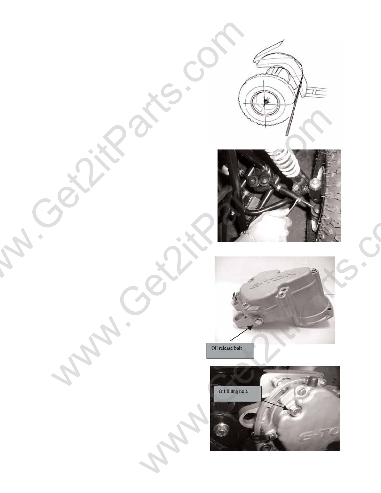
2.14 GEAR OIL
Gear oil needs to be changed every year.
There is a gear oil Drain Plug at the right side of engine.
Remove the Oil Drain Plug Bolt and to drain dirty oil
The oil filling hole is on the engine case beside gear box. Refill
the case with 70cc / 2.4 oz of SAE 80/90 weight gear oil.
2-7
3. ENGINE REMOVAL AND INSTALLATION
www.Get2itParts.com
www.Get2itParts.com
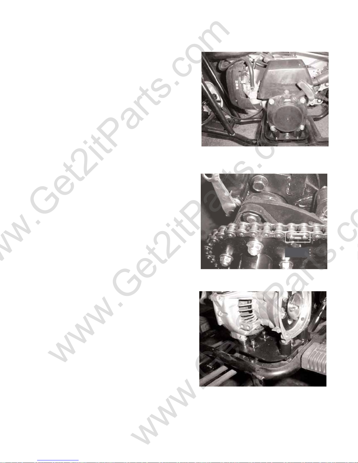
3.1 ENGINE REMOVAL
Remove the seat and the Body Cover. (chapter 10)
Remove the spark plug cap from the spark plug.
Remove the exhaust pipe.
Remove the air cleaner and carburetor Remove the
throttle cable and fuel lines.
Disconnect the wire connectors and remove the wire
from the frame clamps.
Remove the chain protection cover.
Remove the drive chain retaining clip and master link, and
remove the drive chain.
Remove the lower engine hanger nuts and the lower
mission case hanger bolt at the right side.
Remove the engine from the left side.
3.2 ENGINE INSTALLATION
Engine installation is essentially the reverse order of
removal. The torque of engine hanger bolt is 24-30 Nm
Route the wires and cable in reverse order properly.
3-1

4. ENGINE FUEL SYSTEM
www.Get2itParts.com
www.Get2itParts.com
4.1 TROUBLESHOOTING
Engine will not start
Engine idles roughly, stalls, or runs poorly
Lean mixture
Rich mixture
• No fuel in tank
• No fuel to cylinder
• Too much fuel into cylinder
• No spark at plug
• Air cleaner clogged
• Improper adjustment of the idle speed
screw
• Ignition malfunction
• Fuel/air mixture ratio no good
• Air cleaner dirty
• Insulator leaks
• Fuel tank cap breathing hole clogged
• Carburetor fuel jet clogged
• Fuel tank cap breathing hole
clogged
• Fuel filter clogged
• Fuel flows restricted
• Float level in carburetor too low
• Float needle valve in carburetor
faulty
• Float level too high
• Air duct in carburetor is clogged
• Air cleaner dirty
4-1
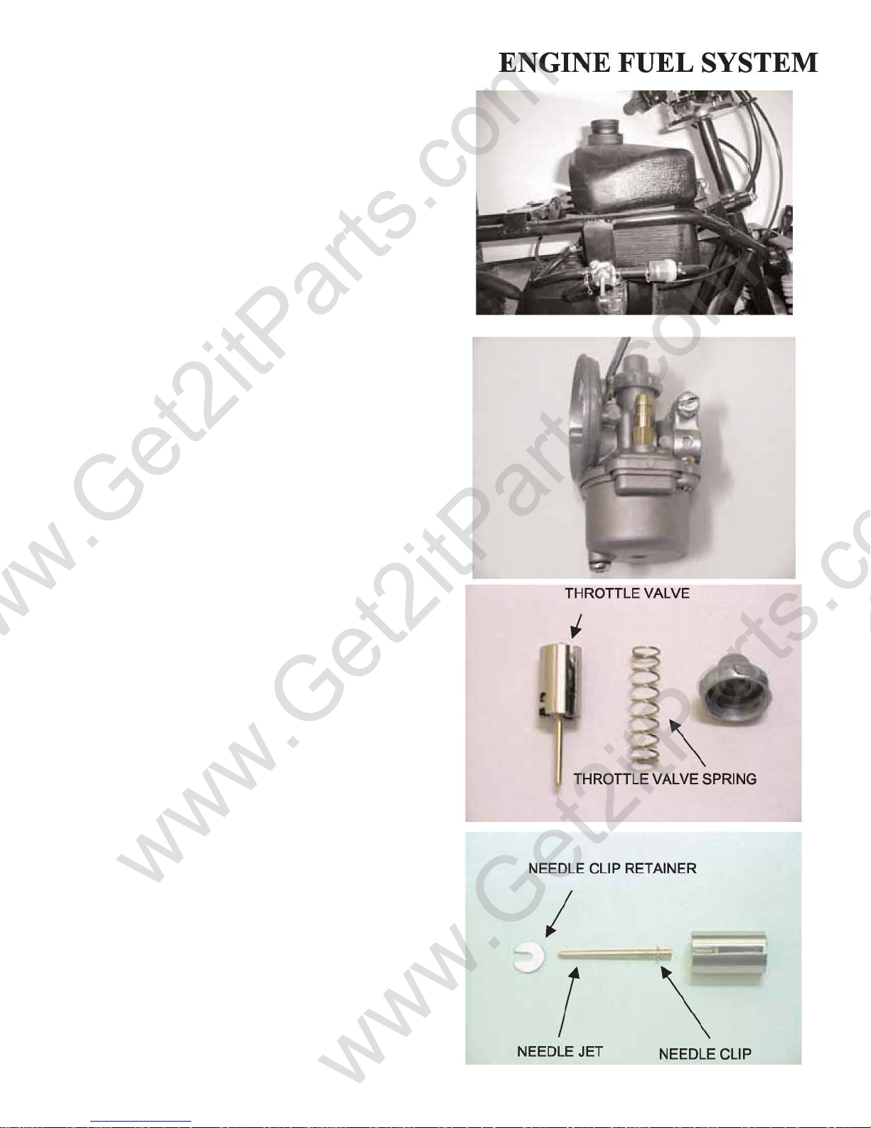
4.2 FUEL TANK
www.Get2itParts.com
www.Get2itParts.com
REMOVAL
Remove the fuel tank cap.
Remove the seat and Body Cover. Disconnect
the fuel line from the carburetor. Unscrew the
fuel tank mounting bolts.
Note: Keep gasoline away from flames or sparks.
Wipe up spilled gasoline immediately.
4.3 THROTTLE VALVE DISASSEMBLY
Remove the throttle top from the carburetor.
4.4 CAUTION
The carburetor top is an integral part of the throttle cable
assembly. The carburetor top cannot be separated from the
assembly without causing damage to the cable.
Never kink or twist control cables. They will not operate
smoothly and may stick if they are kinked or twisted.
Remove the throttle cable from the throttle valve while
depressing the throttle valve spring.
Remove the needle clip retainer.
Remove the needle jet and needle clip.
Inspect the throttle valve and needle jet surface for dirt,
scratches, or wear, and replace if necessary.
4-2
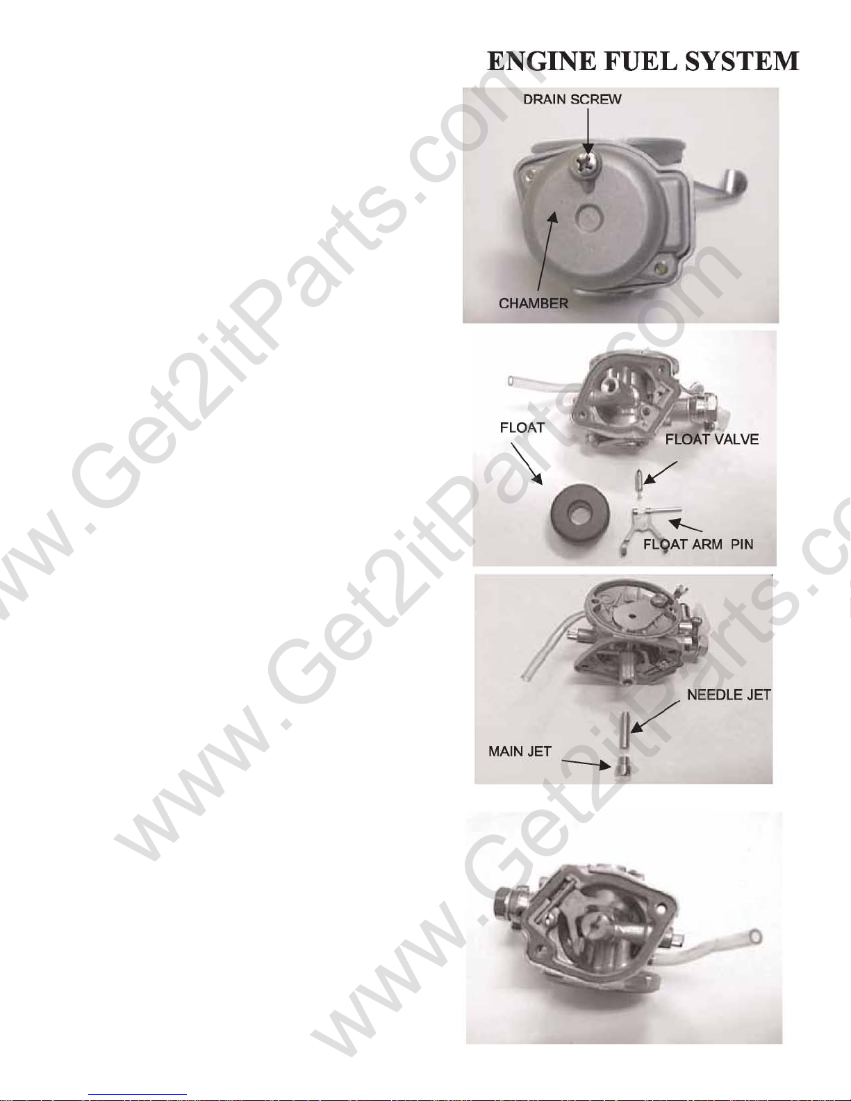
4.5 CARBURETOR REMOVAL
www.Get2itParts.com
www.Get2itParts.com
Loosen the drain screw and drain the gasoline. Remove
the float chamber by removing the two retaining
screws.
Remove the float arm pin.
Remove the float and float valve.
Inspect the float valve for wear or damage.
Remove the main jet and needle jet.
Blow open all jets and body openings with compressed
air.
Inspect the needle jet and main jet.
Check each part for wear or damage.
Clean the passages and jets with compressed air.
4.6 FLOATS, FLOAT VALVE, AND JETS
ASSEMBLY
NOTE:
Handle all jets and needles with care. They can be easily
scored or scratched.
Install the needle jet, main jet, and throttle stop screw.
Install the float valve, float, and float arm pin. Install the
float chamber.
4-3
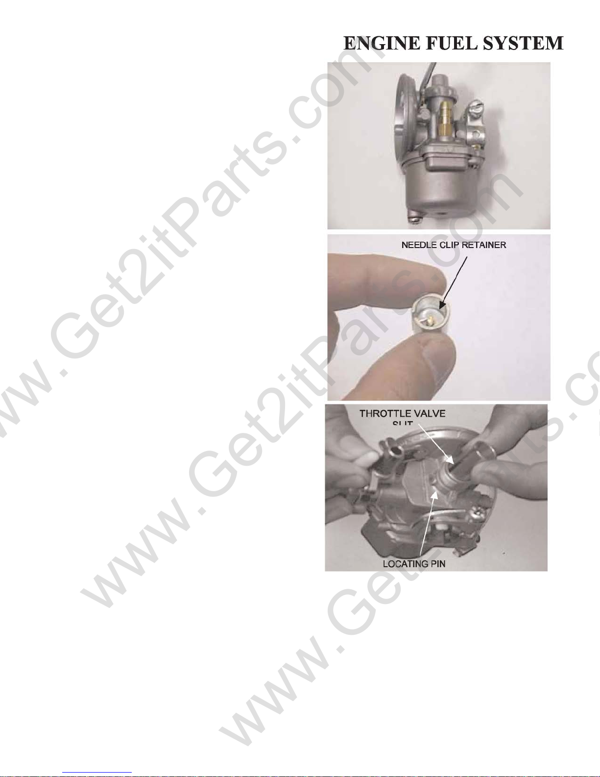
4.7 THROTTLE VALVE ASSEMBLY
www.Get2itParts.com
www.Get2itParts.com
Install the needle clip on the needle jet.
STANDARD SETTING: 2nd groove from the top. Install
the jet needle into the throttle valve and secu re it with the
needle clip retainer.
Install the spring and throttle valve.
Align the throttle valve slit with the locating pin in the
carburetor body and install the carburetor top onto the
carburetor.
Adjust throttle lever free play.
4-4
5. ENGINE COMBUSTION
www.Get2itParts.com
www.Get2itParts.com
SYSTEM
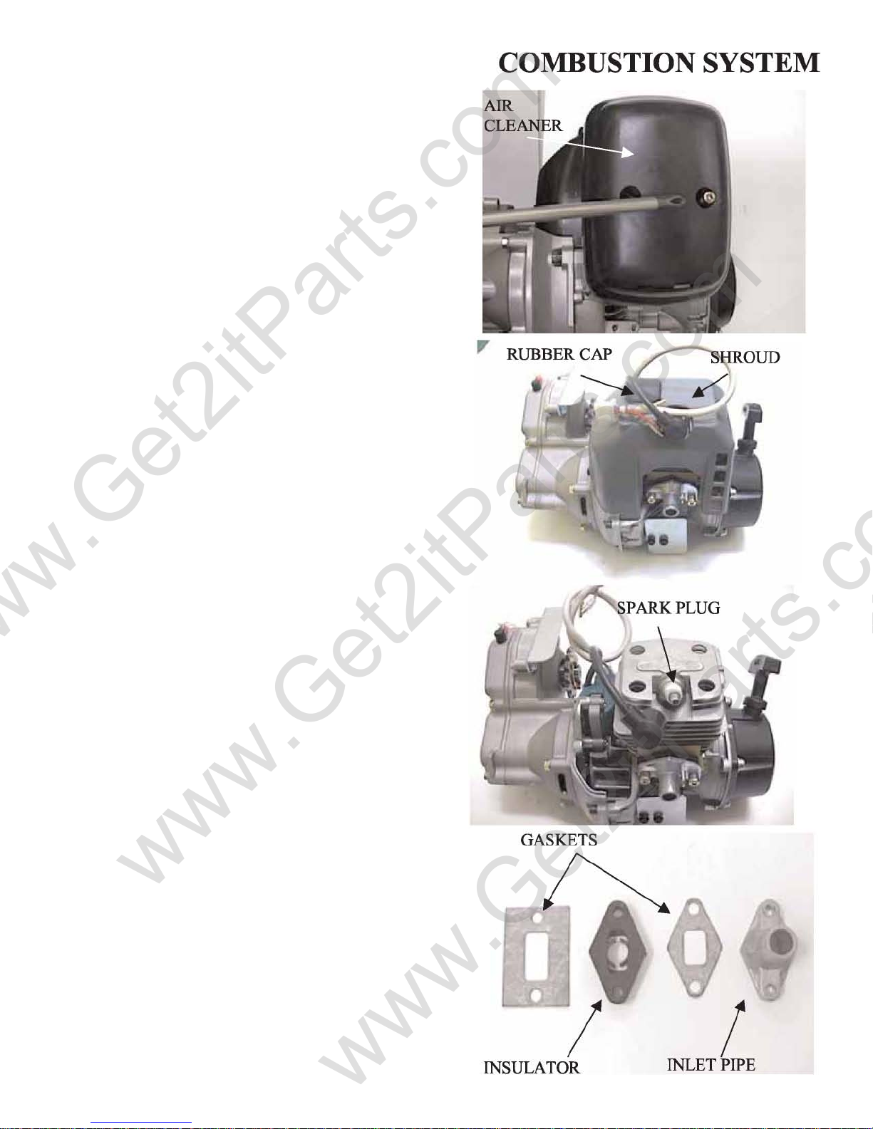
5.1 CYLINDER REMOVAL
Remove the air cleaner and carburetor.
Remove the Ignition Coil assembly.
Remove the cylinder shroud rubber cap and shroud.
Remove the spark plug.
Remove the inlet pipe insulator and gasket.
5-1

Remove the cylinder.
www.Get2itParts.com
www.Get2itParts.com
5.2 INSPECTION
Inspect the cylinder bore for wear or damage.
Measure he cylinder inner diameter at three levels in an X
and Y axis. Calculate cylinder taper at three levels in an X
and Y axis.
Take the maximum reading to determine the taper.
TAPER LIMIT : 0.01mm
Calculate the cylinder out-of-round at three levels in the X
and Y-axis. Take the maximum reading to determine the
out-of-round. Out OF ROUND: 0.10mm
5.3 PISTON REMOVAL
Remove the piston pin clips with needle nose pliers.
NOTE: Don't allow the clips fall into the crankcase.
Press the piston pin out of the piston.
5-2
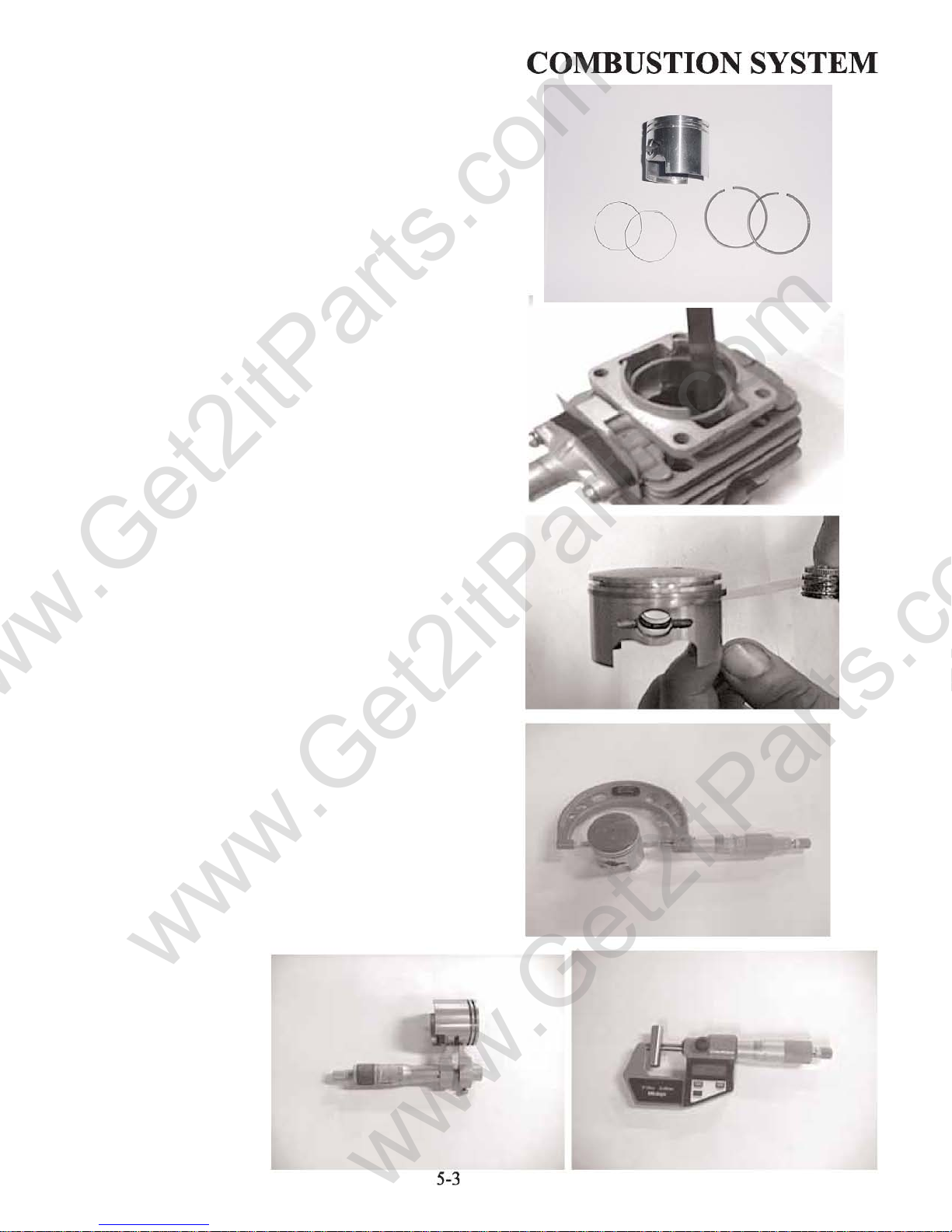
Spread each piston ring and remove it by lifting up at a
www.Get2itParts.com
www.Get2itParts.com
point opposite gap.
Insert each piston ring into the cylinder and measure the
end gap.
SERVICE LIMIT:
Measure the clearance between the ring and groove.
SERVICE LIMIT: 0.09 mm
0.5 mm
Piston
Piston Rings Spacer Rings
Measure the piston outer diameter at 10mm up from the
skirts bottom.
SERVICE LIMIT:
Measure the piston pin outer diameter.
PIN BORE SERVICE
LIMIT:
Measure the piston pin bore.
PIN OUT DIAMETER
SERVICE LIMIT: 0.96 mm
Remove the con-rod 2 bearing and washer.
Inspect the washer and bearings for wear or damage.
10.04 mm
39.9 mm
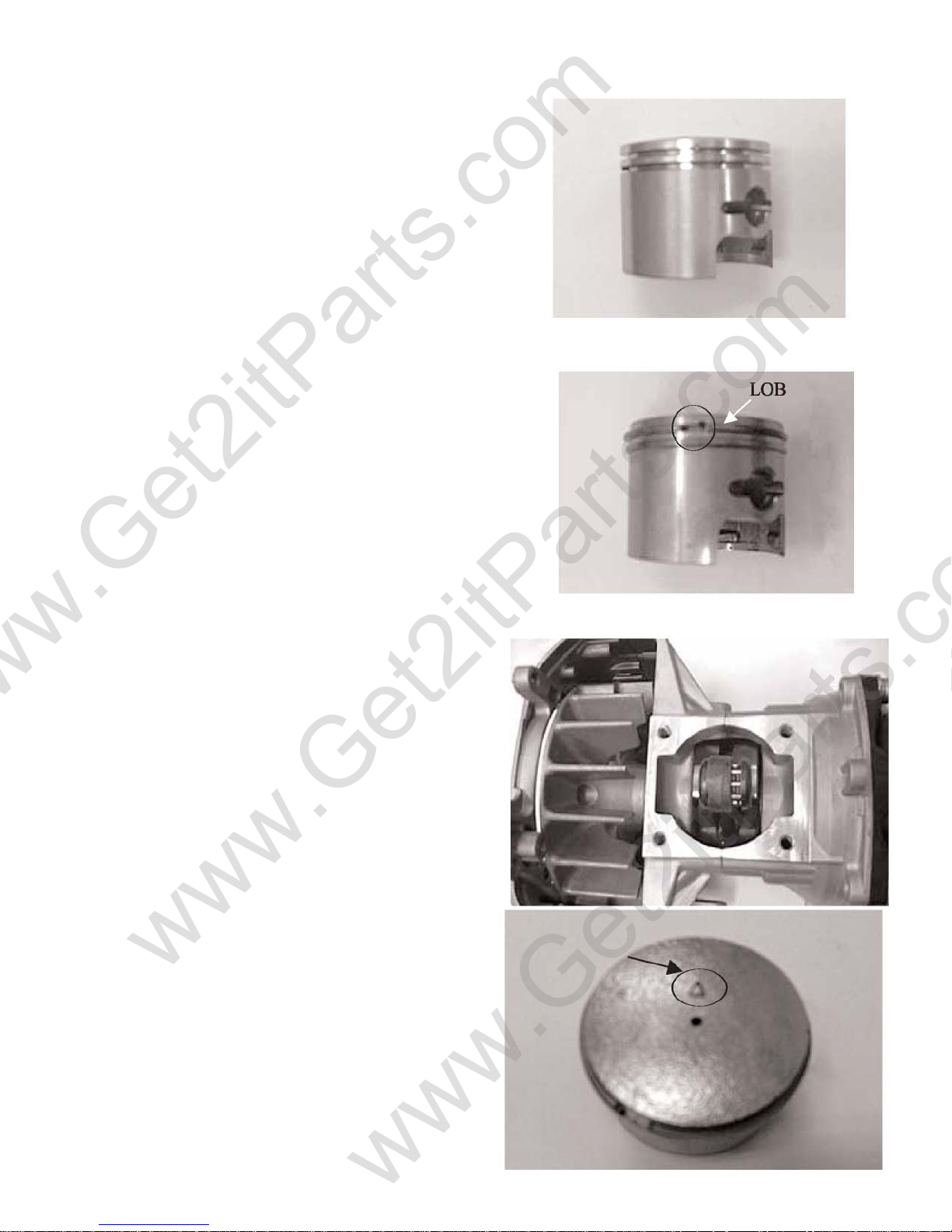
5.4 PISTON RING INSTALLATION
www.Get2itParts.com
www.Get2itParts.com
Clean the piston ring grooves thoroughly and install the
piston rings.
NOTE: Avoid piston and piston ring damage during
installation.
Align the piston rings slit with the lobe on the grooves.
After installation, the rings should be free to rota te in the
ring grooves.
COMBUSTION SYSTEM
5.5 PISTON INSTALLATION
Install the connecting 2 bearing and washer.
Install the piston with its mark on the Inlet Pipe side.
Install the piston, piston pin, and new pin clips.
NOTE:
Don't allow the clip to fall into the crankcase.
5-4
 Loading...