

Eton America Beamer PN2, Beamer II PN2B, Beamer Matrix PN2C, beamer R2-50 Service Manual

www.Get2itParts.com
www.Get2itParts.com
ETON America
Beamer Service Manual
Covers:
Beamer PN2
Beamer II PN2B
Beamer Matrix PN2C

www.Get2itParts.com
www.Get2itParts.com
Table of Contents
1. INFORMATION..................................................................................................................................... 4
1.1 SAFETY ........................................................................................................................................... 4
1.2 NOTES.............................................................................................................................................. 4
1.3 Specifications.................................................................................................................................... 5
1.4 SERIAL NUMBER .......................................................................................................................... 6
1.5 Standard Torque Values.................................................................................................................... 7
2. MAINTENANCE................................................................................................................................... 8
2.1 MAINTENANCE DATA................................................................................................................. 8
2.2 MAINTENANCE SCHEDULE ....................................................................................................... 9
2.3 FUEL TUBE..................................................................................................................................... 9
2.4 THROTTLE OPERATION.............................................................................................................. 9
2.5 THROTTLE CABLE ADJUSTMENT .......................................................................................... 10
2.6 AIR CLEANER.............................................................................................................................. 10
2.7 SPARK PLUG................................................................................................................................ 10
2.8 IDLE SPEED.................................................................................................................................. 11
2.9 BRAKE SYSTEM.......................................................................................................................... 11
2.10 WHEELS AND TIRES................................................................................................................. 12
2.11 GEAR OIL.................................................................................................................................... 12
2.12 ENGINE STOP SWITCH............................................................................................................. 12
2.13 HIGH-LOW BEAM CONTROLLER.......................................................................................... 13
3. ENGINE REMOVAL AND INSTALLATION................................................................................... 14
3.1 ENGINE REMOVAL..................................................................................................................... 14
3.2 ENGINE INSTALLATION............................................................................................................ 16
4. ENGINE FUEL SYSTEM.................................................................................................................... 17
4.1 TROUBLESHOOTING.................................................................................................................. 17
4.2 CARBURETOR.............................................................................................................................. 18
5. ENGINE LUBRICATION AND COOLING SYSTEM...................................................................... 21
5.1 TROUBLESHOOTING.................................................................................................................. 21
5.2 ENGINE LUBRICATION SYSTEM............................................................................................. 21
5.3 CAUTION: Fuel/Oil Ratio ............................................................................................................. 21
5.4 OIL PUMP...................................................................................................................................... 22
5.5 COOLING SYSTEM...................................................................................................................... 23
6. ENGINE COMBUSTION SYSTEM ................................................................................................... 24
6.1 TROUBLESHOOTING.................................................................................................................. 24
6.2 CYLINDER AND PISTON REMOVAL....................................................................................... 25
6.3 CYLINDER AND PISTON INSPECTION ................................................................................... 25
6.4 INSTALLATION ........................................................................................................................... 27
7. TRANSMISSION SYSTEM................................................................................................................ 29
7.1 TROUBLESHOOTING.................................................................................................................. 29
7.2 THE PARTS DRAWING OF TRANSMISSION SYSTEM.......................................................... 29
7.3 TRANSMISSION POWER PATH ................................................................................................ 30
7.4 AUTOMATIC CONTINUOUS VARIABLE TRANSMISSION.................................................. 31
7.5 CONTINUOUS VARIABLE TRANSMISSION........................................................................... 31
7.6 TRANSMISSION BOX ................................................................................................................. 32
Beamer Rev-2.0.2 Page 2 of 55 11/21/2005

www.Get2itParts.com
www.Get2itParts.com
7.6 TRANSMISSION BOX ................................................................................................................. 32
7.7 ELECTRIC STARTER MOTOR................................................................................................... 33
7.8 KICK STARTER............................................................................................................................ 33
8. FRONT WHEEL, BRAKE AND STEERING SYSTEM.................................................................... 35
8.1 TROUBLESHOOTING.................................................................................................................. 35
8.2 MAINTANENCE DATA............................................................................................................... 35
8.3 SPEEDOMETER CABLE REMOVAL......................................................................................... 36
8.4 HANDLEBAR REPLACEMENT.................................................................................................. 36
8.5 FRONT WHEEL ............................................................................................................................ 37
8.6 FRONT BRAKE............................................................................................................................. 38
8.7 FRONT FORK ................................................................................................................................ 40
9. REAR WHEELAND BRAKE SYSTEM......................................................................................... 41
9.1 TROUBLESHOOTING.................................................................................................................. 41
9.2 MAINTENANCE DATA............................................................................................................... 41
9.3 REAR WHEEL REMOVAL.......................................................................................................... 41
9.4 REAR WHEEL INSPECTION....................................................................................................... 42
9.5 REAR BRAKE ............................................................................................................................... 42
9.6 REAR SHOCK ABSORBER PARTS DRAWING ....................................................................... 43
10. PLASTIC BODY PARTS............................................................................................................... 44
10.1 FRONT FENDER......................................................................................................................... 44
10.2 BODY COVER............................................................................................................................. 44
11. ELECTRICAL SYSTEM ............................................................................................................... 48
11.1 TROUBLESHOOTING................................................................................................................ 48
11.2 IGNITION COIL.......................................................................................................................... 49
11.3 IGNITION TIMING..................................................................................................................... 49
11.4 BATTERY INSPECTION AND MAINTENANCE.................................................................... 50
11.5 STARTER MOTOR ..................................................................................................................... 52
11.6 WIRING DIAGRAMS ................................................................................................................. 53
Beamer Rev-2.0.2 Page 3 of 55 11/21/2005

www.Get2itParts.com
www.Get2itParts.com
1. INFORMATION
1.1 SAFETY
Gasoline is extremely flammable and is explosive under certain conditions.
Do not smoke or allow sparks or flames in your work area.
Never run the engine in a closed area. The exhaust contains poisonous carbon monoxide gas that may
cause loss of consciousness and lead to death.
The battery electrolyte contains sulfuric acid. Protect your eyes, skin and clothing. If you spill the
electrolyte on your skin or in your eyes, flush thoroughly with water. Call a doctor if electrolyte gets in
your eyes.
1.2 NOTES
All information, illustrations, directions and specifications included in this publication are based on the
latest product information available at the time of approval for printing.
E-TON Dynamic Technology Industry Co., Ltd. reserves the right to make changes at any time without
notice and without incurring any obligation whatever.
No part of this publication may be reproduced without written permission.
Beamer Rev-2.0.2 Page 4 of 55 11/21/2005
www.Get2itParts.com
www.Get2itParts.com
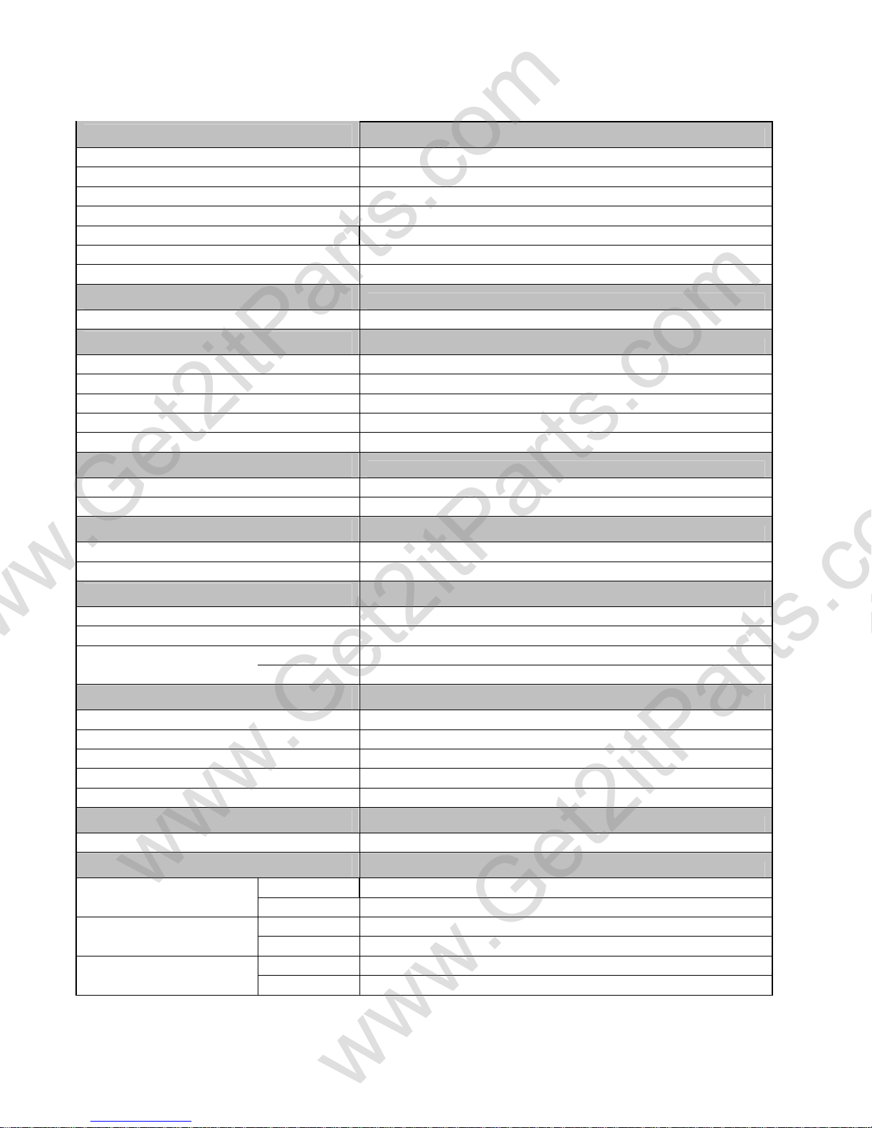
1.3 Specifications
Engine
Type Two cycle air cooled oil injected
Displacement 49.3cc
Bore / Stroke φ40.0 * 39.2mm
Compression - Ratio / Pressure 6.8 : 1 / 90-120psi
Torque / BHP 5.2N m @ 7000rpm / 1.5BHP
Estimated MPG 65mpg/795mpg
Starting Electrical with Kick starter back up
Transmission
Type Automatic (C.V.T. V-Belt)
Chassis
Overall Length 1830mm / 72.0"
Overall Width 650mm / 25.6"
Overall High 1100mm / 43.3"
Wheel Base 1260mm / 49.6"
Dry Weight 82kg / 180.7lb
Suspension
Front Telescopic Fork
Rear Unit Swing Arm / Single Shock
Brakes
Front Hydraulic Disc
Rear Mechanical Drum
Tires
Front 120/90-10
Rear 130/90-10
Tire Pressure
Front Front 18psi / 1.25kg/cm2 (Cold)
Rear
Carburetor
Make/Size
Main Jet
Pilot Jet
Air Mixture Adjustment
Idle Speed
Battery
Jell Acid (Maintenance Free)
Fluids
Fuel
2 Cycle Oil
Transmission
Type Unleaded Gasoline 89 octane
Volume 5.5liters / 1.5gal
Type
Volume 1.1 liters / 1.2qts
Type SAE 80/90 weight
Volume 100cc / 3.4oz
Rear 25psi / 1.75kg/cm2 (Cold)
Mikuni 18mm (Manual Coke)
85mm
20mm
Back out ¾ - 1¼ turns
Idle 1700 - 1900rpm
12V-4AH/5AH - GTX5L-BS
High grade synthetic 2 cycle injector oil
Beamer Rev-2.0.2 Page 5 of 55 11/21/2005
www.Get2itParts.com
www.Get2itParts.com
Spark Plug
NGK (recommended)
Nipendenso
Champion
Electrode Gap 0.6-0.7mm / 0.023"
GVWR
GAWR (Front)
GAWR (Rear)
Available Colors
*Subject to availability
BPR7HS
W22FRP-U
QL82YC
240kg. / 530lbs.
76kg. / 167lbs.
165kg. / 164lbs.
Red
Blue
Yellow
Black
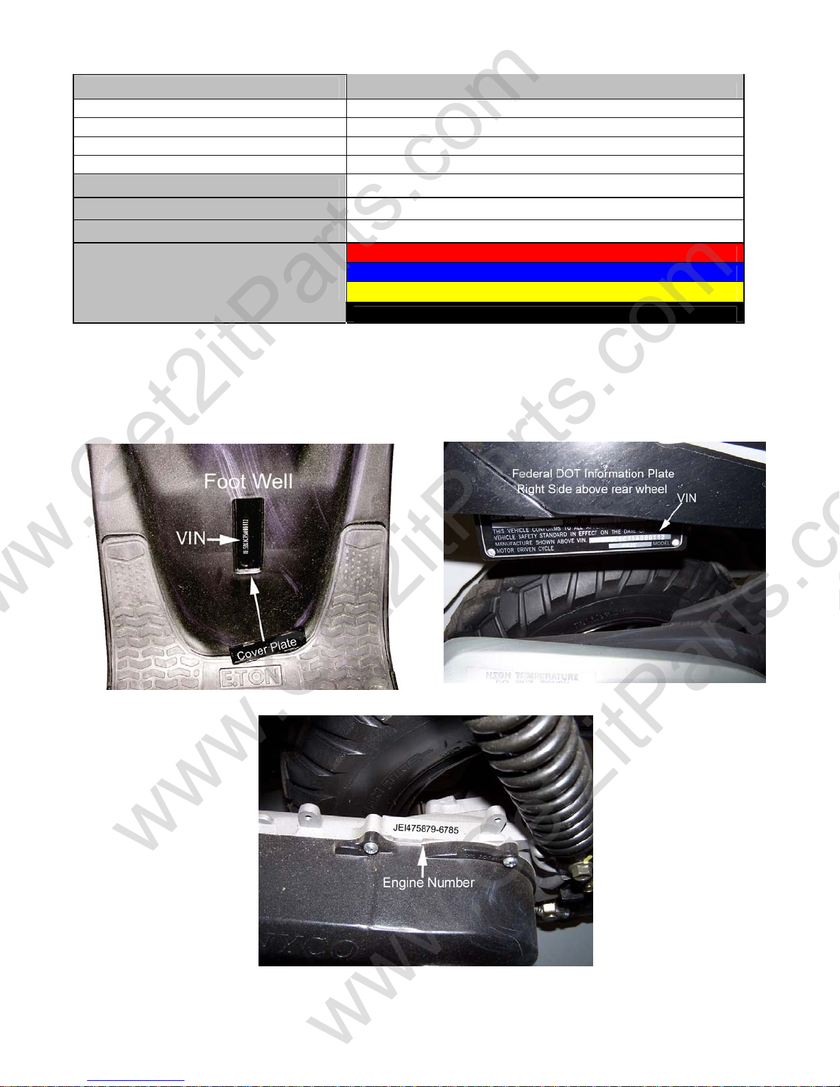
1.4 SERIAL NUMBER
The frame serial number is stamped on the front of the frame, at the front of the footrest plate.
The engine serial number is stamped on the left side of the engine crankcase.
Beamer Rev-2.0.2 Page 6 of 55 11/21/2005

www.Get2itParts.com
www.Get2itParts.com
1.5 Standard Torque Values
ENGINE
¾ Cylinder head nut 28-30 N-m (20.7-22.1 lb./ft)
¾ Spark plug 12-19 N-m (8.9-14.0 lb./ft)
¾ Cylinder head bolt 20-30 N-m (14.8-22.1 lb./ft)
¾ Alternator bolt 8-12 N-m (5.9- 8.9 lb./ft)
FRAME
¾ Handlebar upper holder bolt 24-30 N-m (17.7-22.1 lb./ft)
¾ Steering shaft nut 50-60 N-m (36.9-44.3 lb./ft)
¾ Steering shaft bushing holder nut 24-30 N-m (17.7-22.1 lb./ft)
¾ Wheel rim bolt 18-25 N-m (13.3-18.4 lb./ft)
¾ Tie rod lock nut 35-43 N-m (25.8-31.7 lb./ft)
¾ King pin nut 30-40 N-m (22.1-29.5 lb./ft)
¾ Handlebar lower holder nut 40-48 N-m (29.5-35.4 lb./ft)
¾ Front wheel bolt 24-30 N-m (17.7-22.1 lb./ft)
¾ Front axle nut 55-65 N-m (40.6-47.9 lb./ft)
¾ Front brake arm nut 4-7 N-m (3.0- 5.2 lb./ft)
¾ Rear brake arm nut 7-12 N-m (5.2- 8.9 lb./ft)
¾ Rear axle nut 60-80 N-m (44.3-59.0 lb./ft)
¾ Rear wheel bolt 24-30 N-m (17.7-22.1 lb./ft)
¾ Exhaust muffler mounting bolt 30-35 N-m (22.1-25.8 lb./ft)
¾ Engine hanger bolt 24-30 N-m (17.7-22.1 lb./ft)
Beamer Rev-2.0.2 Page 7 of 55 11/21/2005

www.Get2itParts.com
www.Get2itParts.com
2. MAINTENANCE
2.1 MAINTENANCE DATA
2.2 MAINTENANCE SCHEDULE
2.3 FUEL TUBE
2.4 THROTTLE OPERATION
2.5 THROTTLE CABLE ADJUSTMENT
2.6 AIR CLEANER
2.7 SPARK PLUG
2.8 IDLE SPEED
2.9 BRAKE SYSTEM
2.10 WHEELS AND TIRES
2.11 STEERING SYSTEM
2.12 GEAR OIL
2.1 MAINTENANCE DATA
SPECIFICATION
SPARK PLUG:
SPARK PLUG GAP: 0.6-0.7 mm
RECOMMENDED SPARK PLUGS: NGK BPR7HS
THROTTLE LEVER FREE PLAY: 5-10 mm
IDLE SPEED: 1600±100 rpm
BRAKE LEVER FREE PLAY: 15-25 mm
TIRES:
FRONT TIRE SIZE 120/90-10
REAR TIRE SIZE 130-90-10
FRONT/REAR TIRE PRESSURE 2.5± 0.3 kgf/cm2
TORQUE VALUES
SPARK PLUG 12-19 N-m
TIE-ROD LOCK NUT 35-43 N-m
LUBRICATION:
ENGINE OIL JASO FC Grade or same degree oil
GEAR LUBRICATION OIL SAE 40
Beamer Rev-2.0.2 Page 8 of 55 11/21/2005
www.Get2itParts.com
www.Get2itParts.com
2.2 MAINTENANCE SCHEDULE
The maintenance intervals in the follow table are based upon average riding conditions. Riding in
unusually dusty areas may require more frequent servicing. E-TON recommends that all maintenance
and inspections be performed ONLY by a qualified and fully trained technician.
Fuel Line I
Throttle Operation I I I
Air Filter system &
Element
Spark Plug I R
Carburetor Idle Speed I I I
Brake Shoe Wear I I I
Brake System I I
Nut, Bolt, Fastener I I
Wheels & Wheel Nuts I I
Steering System
Suspension System I I
C.V.T. Air Filter C R
Air Induction Reed Valve I C/R
Transmission Gear Oil I R
Note –
I: Inspect and Clean, Adjust, Lubricate, or Replace (if necessary)
C: Clean
L: Lubricate
R: Replace
INITIAL
SERVICE
(First week) (Every 30 operating
I C R
REGULAR SERVICE
days)
I
EVERY
YEAR
I
I
I
I
2.3 FUEL TUBE
Inspect the fuel lines for deterioration, damage, or
leaks, and replace if necessary.
2.4 THROTTLE OPERATION
Inspect for smooth throttle lever full opening and
automatic full closing in all steering positions.
Inspect for deterioration, damage, or kinking
in the throttle cable. Replace if necessary.
Check the throttle lever. Free play is 5-10 mm at the tip
of the throttle lever.
Disconnect the throttle cable at the upper end.
Lubricate the cable with commercially available lubricant to prevent premature wear.
Beamer Rev-2.0.2 Page 9 of 55 9/21/2006
www.Get2itParts.com
www.Get2itParts.com
2.5 THROTTLE CABLE
ADJUSTMENT
Slide the rubber adjuster cap off the throttle
housing, loosen the locking nut, and adjust the
free play of the throttle lever by turning the
adjuster on the throttle housing. Inspect the free
play of the throttle lever.
This free play should be 5-10mm.
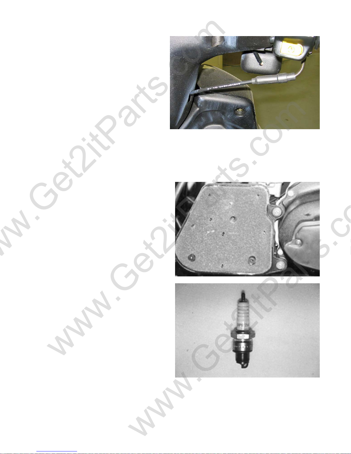
2.6 AIR CLEANER
Unscrew the air cleaner cover screws.
Pull out the air filter element from the air cleaner
case. Wash the element in non-flammable solvent.
Squeeze out the solvent thoroughly.
Let it dry. Soak the filter element in gear oil and
then squeeze out the excess oil.
Install the element into the air cleaner carefully.
2.7 SPARK PLUG
The spark plug is located at the front of the
engine. Disconnect the spark plug cap and remove
the spark plug. Check the spark plug electrodes
for wear. Change the spark plug if the electrodes
and insulator tip appear unusually fouled or
burned.
Discard the spark plug if there is apparent wear or
if the insulator is cracked or chipped.
The spark plug gap should be set to 0.6-0.7mm.
With the sealing washer attached, thread the spark
plug in by hand to prevent cross threading.
Torque the spark plug to 12-19 N-m.
Beamer Rev-2.0.2 Page 10 of 55 11/21/2005
j
www.Get2itParts.com
www.Get2itParts.com
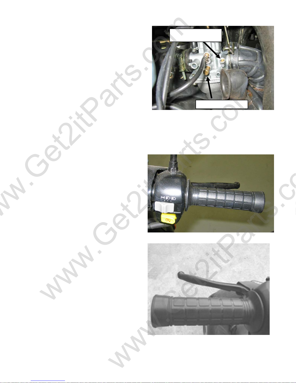
2.8 IDLE SPEED
Connect a tachometer.
Warm up the engine for at least 10 minutes.
Turn the idle-speed adjust screw on the carburetor
to obtain the idle speed. "Turn in" (clockwise)
to get higher speed. "Turn out" (counter clockwise)
to get lower speed.
IDLE SPEED: 1600±100 rpm
2.9 BRAKE SYSTEM
Inspect the front brake lever and cable for
excessive play or other damage.
Replace or repair if necessary.
Measure the free play of the brake lever at the end
of the brake lever.
The standard of free play is 15-25 mm.
Inspect the rear brake lever and cable for
excessive play or other damage.
Replace or repair if necessary.
Measure the free play of the rear brake lever at
the end of the lever. The standard is 15-25 mm.
Adjust the free play of the rear brake lever by
turning the adjuster on the rear axle.
Air Mixture
ustment Screw
Ad
Idle Adjustment Screw
Beamer Rev-2.0.2 Page 11 of 55 11/21/2005
t
www.Get2itParts.com
www.Get2itParts.com
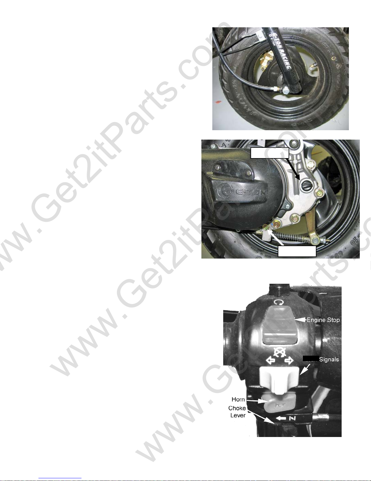
2.10 WHEELS AND TIRES
Inspect the tire surfaces for cuts, nails, or other sharp
objects. Check the tire pressure at cold tire condition.
The standard tire pressure is 2.5±0.3 kgf/cm2
2.11 GEAR OIL
Transmission gear oil needs to be changed every year
or after every 3000 miles of service.
The drain bolt is located at the rear of engine.
Remove the drain bolt and loosen the fill bolt to drain
the transmission gear box.
Inspect the drained oil for foreign materials. If the oil
contains a high concentration of metal shavings or
powder, disassemble the transmission for further
inspection.
Reinstall the drain bolt and refill the gear box with
100cc
/ 3.4oz of SAE 80-90 Gear Oil
Note: for best results, drain the transmission while
the engine is warm.
Fill Plug
Drain Bol
2.12 ENGINE STOP SWITCH
The engine stop switch is located beside the left handle bar.
In an emergency, pushing this switch will stop the engine.
The stop switch must be place in the on position, the top of the
switch pressed down, for the engine to start.
If your engine fails to start, check the switch.
Beamer Rev-2.0.2 Page 12 of 55 11/21/2005
www.Get2itParts.com
www.Get2itParts.com
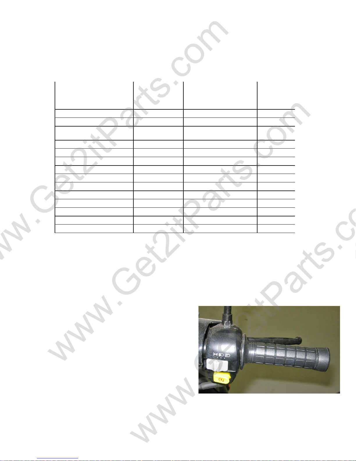
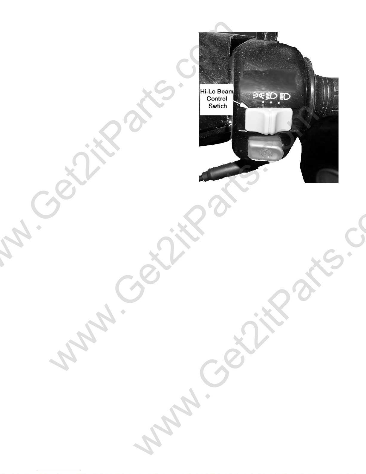
2.13 HIGH-LOW BEAM CONTROLLER
This controller is located beside right handle bar and
controls the headlight intensity setting.
When the switch is placed in the full right position, the
headlights are set to illuminate at 100% intensity. In the
center position the headlight will illuminate at 60%
intensity. Placed in the far left position, the headlights
will be off.
NOTE: It is recommended that you have the headlight
on at all times when operating the vehicle to improve
your visibility to other traffic.
Beamer Rev-2.0.2 Page 13 of 55 11/21/2005
www.Get2itParts.com
www.Get2itParts.com
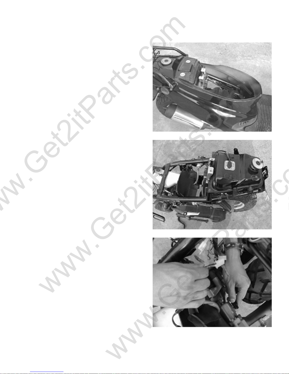
3. ENGINE REMOVAL AND INSTALLATION
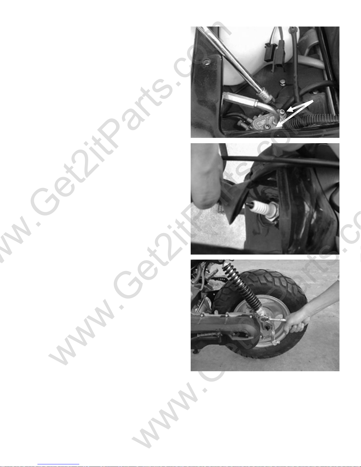
3.1 ENGINE REMOVAL
Remove the seat, helmet box, and body cover.
(See chapter 10 for complete instructions)
Disconnect oil tube, fuel tube, and vacuum line tube.
Disconnect the wires of the A/C generator and the
starter motor.
Beamer Rev-2.0.2 Page 14 of 55 11/21/2005
www.Get2itParts.com
www.Get2itParts.com
Disconnect the wires of the carburetor and the
throttle cable.
Remove the cap from the spark plug.
Remove the bolt at the low end of the rear shock.
Beamer Rev-2.0.2 Page 15 of 55 11/21/2005
www.Get2itParts.com
www.Get2itParts.com
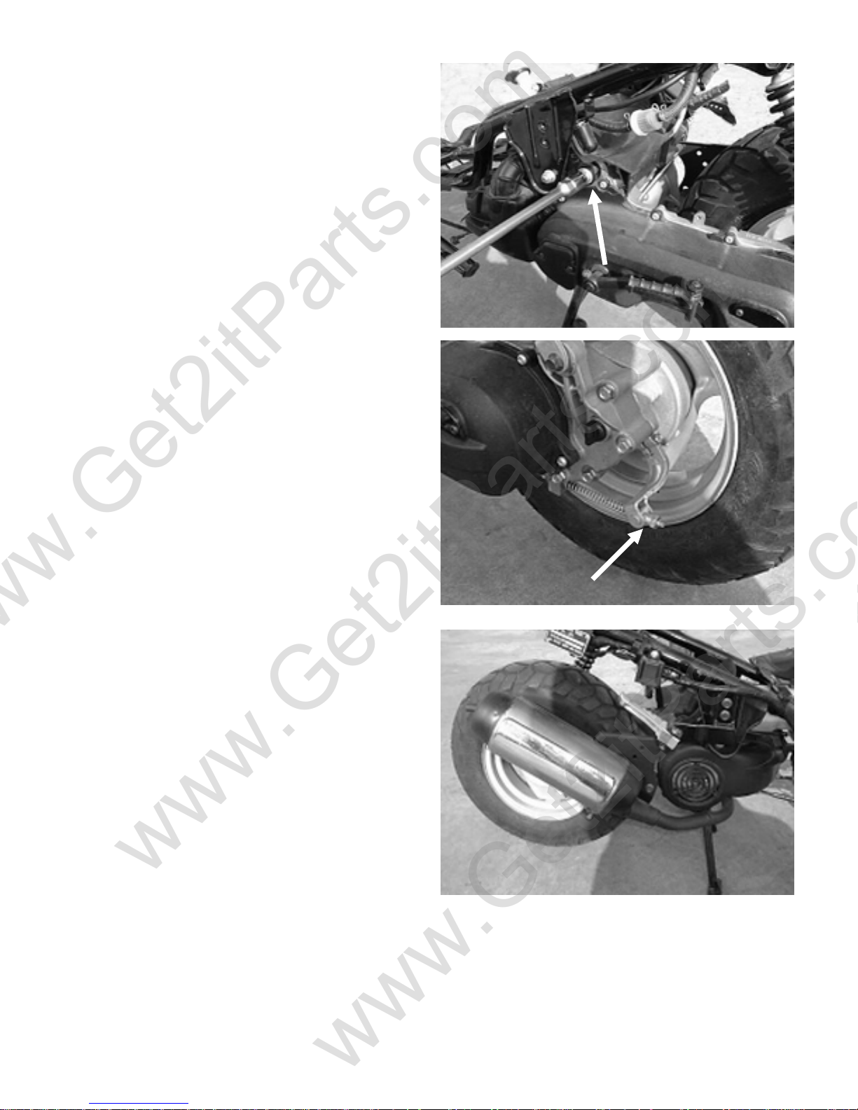
Remove the engine hanger nut.
Remove the rear brake cable adjusting nut.
Pull the engine out from the frame.
3.2 ENGINE INSTALLATION
Install engine in reverse order of disassembly.
Torque value:
M8 nut 15 - 22 lbf-ft
M10 nut 22 - 29 lbf-ft
M12 nut 36 – 43 lbf-ft
After installing the engine, check the parts below:
o All connections (A/C generator,
starter motor, etc)
o Carburetor throttle cable
o Rear brake cable
o Oil tubes and fuel tubes
Beamer Rev-2.0.2 Page 16 of 55 11/21/2005
www.Get2itParts.com
www.Get2itParts.com
4. ENGINE FUEL SYSTEM
4.1 TROUBLESHOOTING
ENGINE WILL NOT START
ENGINE IDLES UNSTEADILY, STALLS,
OR RUNS POORLY
LEAN MIXTURE
¾ NO FUEL IN TANK
¾ NO FUEL IN CYLINDER
¾ TOO MUCH FUEL INTO CYLINDER
¾ NO SPARK AT PLUG
¾ AIR CLEANER CLOGGED
¾ IMPROPER ADJUSTMENT OF THE
IDLE SPEED SCREW AT CARBURETOR
¾ IGNITION MALFUNCTION
¾ FUEL/AIR MIXTURE RATIO TOO LEAN OR
TOO RICH
¾ AIR CLEANER DIRTY
¾ INSULATOR LEAKS
¾ FUEL TANK CAP BREATHING HOLE
CLOGGED
¾ CARBURETOR FUEL JET CLOGGED
¾ FUEL TANK CAP BREATHING HOLE
CLOGGED
¾ FUEL FILTER CLOGGED
¾ FUEL FLOWS IN THE TUBE IRREGULARLY
¾ FLOAT LEVEL IN CARBURETOR TOO LOW
RICH MIXTURE
Beamer Rev-2.0.2 Page 17 of 55 11/21/2005
¾ FLOAT NEEDLE VALVE IN CARBURETOR
FAULTY
¾ FLOAT LEVEL TOO HIGH
¾ AIR DUCT IN CARBURETOR IS CLOGGED
¾ AIR CLEANER DIRTY
r
r
www.Get2itParts.com
www.Get2itParts.com
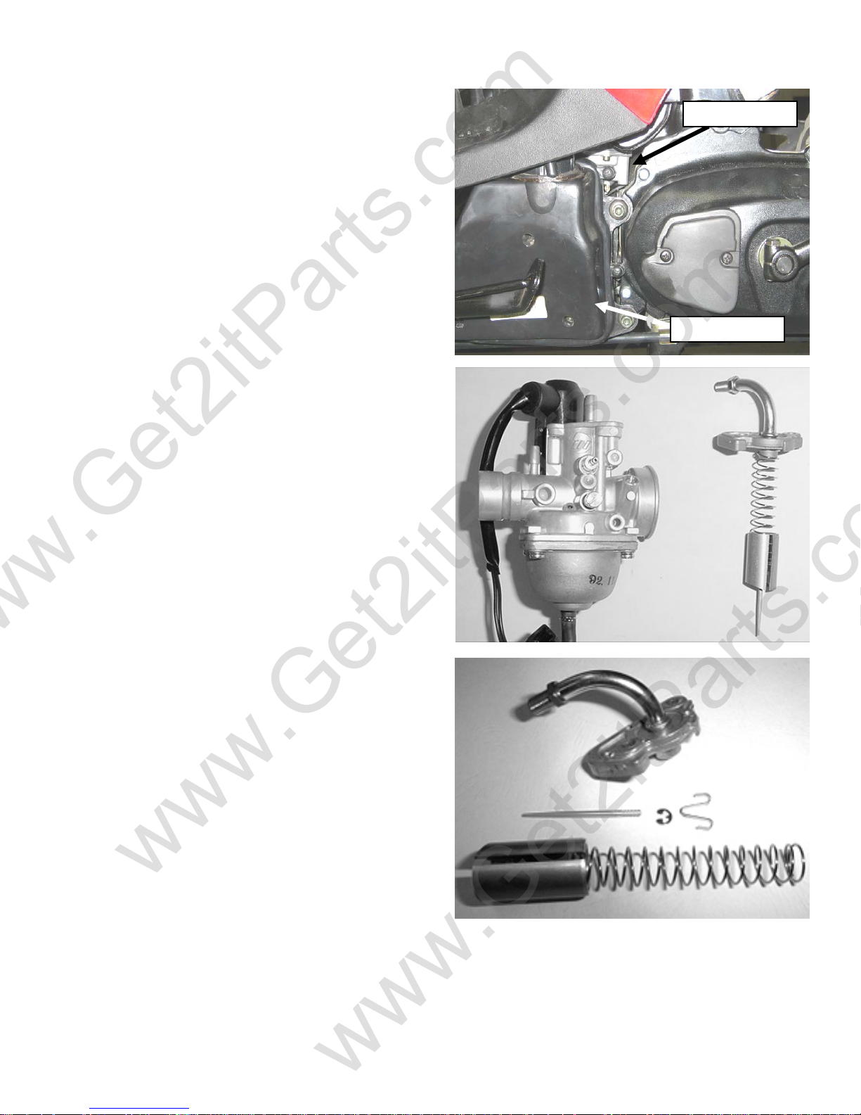
4.2 CARBURETOR
REMOVAL
Remove the air cleaner.
Disconnect the fuel line and auto-choke electric wire.
Unscrew the intake pipe mounting bolts at the
carburetor, and then remove the carburetor.
Note: Before removing carburetor, you must shut the
fuel flow off.
Remove the carburetor cap.
Remove the throttle cable from the throttle valve
while depressing the throttle valve spring.
Remove the needle clip retainer, the jet needle, and
needle clip. Inspect the throttle valve and jet needle
surface for wear, scratches, or dirt.
Carbureto
Air Cleane
Beamer Rev-2.0.2 Page 18 of 55 11/21/2005
t
t
www.Get2itParts.com
www.Get2itParts.com
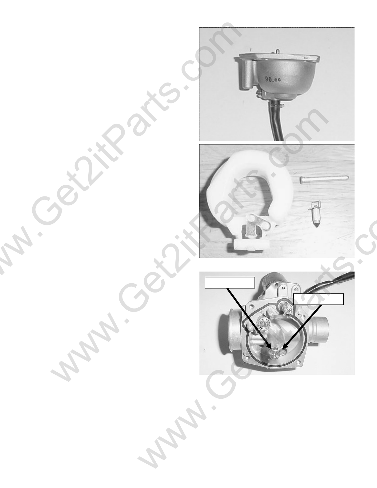
DISASSEMBLY
Unscrew the float chamber screws and remove the
float chamber.
Disassemble the float arm pin, float and float needle
valve.
Inspect the seat of the float needle valve for wear or
damage.
Disassemble the idle jet, main jet, idle speed
adjustment screw, and idle mixture adjustment screw.
Inspect all jets and screws for wear or damage.
Clean the passages and jets with compressed air.
ASSEMBLY
Clean all parts in solvent and blow it dry with
compressed air. Assembly is the reverse order of
disassembly.
Main Je
Pilot Je
Beamer Rev-2.0.2 Page 19 of 55 11/21/2005
www.Get2itParts.com
www.Get2itParts.com
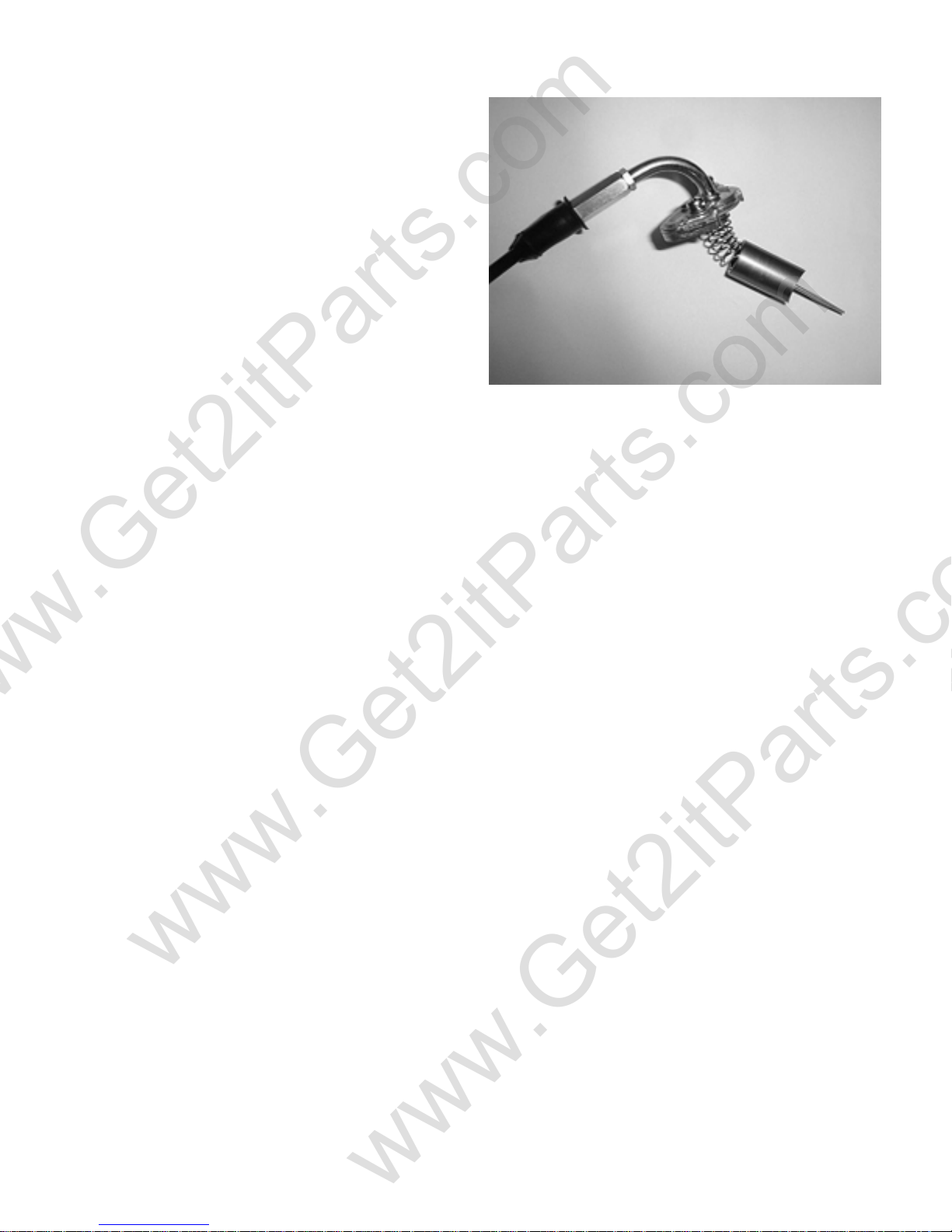
THROTTLE VALVE ASSEMBLY
Install the needle clip on the jet needle.
Install the jet needle into the throttle valve.
Assemble the throttle cable, spring, and throttle
valve. Align the throttle valve groove with the idle
speed adjust screw and install the carburetor cap to
the carburetor.
Beamer Rev-2.0.2 Page 20 of 55 11/21/2005
 Loading...