

Page 1

www.Get2itParts.com
www.Get2itParts.com
ETON America
Beamer Service Manual
Covers:
Beamer PN2
Beamer II PN2B
Beamer Matrix PN2C
Page 2
www.Get2itParts.com
www.Get2itParts.com
Table of Contents
1. INFORMATION..................................................................................................................................... 4
1.1 SAFETY ........................................................................................................................................... 4
1.2 NOTES.............................................................................................................................................. 4
1.3 Specifications.................................................................................................................................... 5
1.4 SERIAL NUMBER .......................................................................................................................... 6
1.5 Standard Torque Values.................................................................................................................... 7
2. MAINTENANCE................................................................................................................................... 8
2.1 MAINTENANCE DATA................................................................................................................. 8
2.2 MAINTENANCE SCHEDULE ....................................................................................................... 9
2.3 FUEL TUBE..................................................................................................................................... 9
2.4 THROTTLE OPERATION.............................................................................................................. 9
2.5 THROTTLE CABLE ADJUSTMENT .......................................................................................... 10
2.6 AIR CLEANER.............................................................................................................................. 10
2.7 SPARK PLUG................................................................................................................................ 10
2.8 IDLE SPEED.................................................................................................................................. 11
2.9 BRAKE SYSTEM.......................................................................................................................... 11
2.10 WHEELS AND TIRES................................................................................................................. 12
2.11 GEAR OIL.................................................................................................................................... 12
2.12 ENGINE STOP SWITCH............................................................................................................. 12
2.13 HIGH-LOW BEAM CONTROLLER.......................................................................................... 13
3. ENGINE REMOVAL AND INSTALLATION................................................................................... 14
3.1 ENGINE REMOVAL..................................................................................................................... 14
3.2 ENGINE INSTALLATION............................................................................................................ 16
4. ENGINE FUEL SYSTEM.................................................................................................................... 17
4.1 TROUBLESHOOTING.................................................................................................................. 17
4.2 CARBURETOR.............................................................................................................................. 18
5. ENGINE LUBRICATION AND COOLING SYSTEM...................................................................... 21
5.1 TROUBLESHOOTING.................................................................................................................. 21
5.2 ENGINE LUBRICATION SYSTEM............................................................................................. 21
5.3 CAUTION: Fuel/Oil Ratio ............................................................................................................. 21
5.4 OIL PUMP...................................................................................................................................... 22
5.5 COOLING SYSTEM...................................................................................................................... 23
6. ENGINE COMBUSTION SYSTEM ................................................................................................... 24
6.1 TROUBLESHOOTING.................................................................................................................. 24
6.2 CYLINDER AND PISTON REMOVAL....................................................................................... 25
6.3 CYLINDER AND PISTON INSPECTION ................................................................................... 25
6.4 INSTALLATION ........................................................................................................................... 27
7. TRANSMISSION SYSTEM................................................................................................................ 29
7.1 TROUBLESHOOTING.................................................................................................................. 29
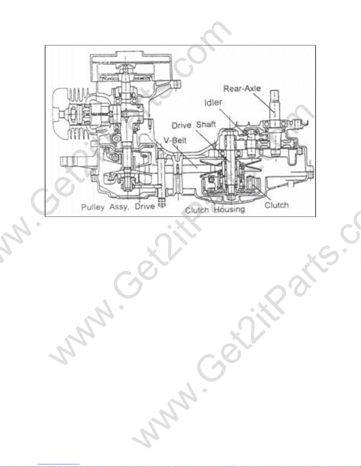
7.2 THE PARTS DRAWING OF TRANSMISSION SYSTEM.......................................................... 29
7.3 TRANSMISSION POWER PATH ................................................................................................ 30
7.4 AUTOMATIC CONTINUOUS VARIABLE TRANSMISSION.................................................. 31
7.5 CONTINUOUS VARIABLE TRANSMISSION........................................................................... 31
7.6 TRANSMISSION BOX ................................................................................................................. 32
Beamer Rev-2.0.2 Page 2 of 55 11/21/2005
Page 3
www.Get2itParts.com
www.Get2itParts.com
7.6 TRANSMISSION BOX ................................................................................................................. 32
7.7 ELECTRIC STARTER MOTOR................................................................................................... 33
7.8 KICK STARTER............................................................................................................................ 33
8. FRONT WHEEL, BRAKE AND STEERING SYSTEM.................................................................... 35
8.1 TROUBLESHOOTING.................................................................................................................. 35
8.2 MAINTANENCE DATA............................................................................................................... 35
8.3 SPEEDOMETER CABLE REMOVAL......................................................................................... 36
8.4 HANDLEBAR REPLACEMENT.................................................................................................. 36
8.5 FRONT WHEEL ............................................................................................................................ 37
8.6 FRONT BRAKE............................................................................................................................. 38
8.7 FRONT FORK ................................................................................................................................ 40
9. REAR WHEELAND BRAKE SYSTEM......................................................................................... 41
9.1 TROUBLESHOOTING.................................................................................................................. 41
9.2 MAINTENANCE DATA............................................................................................................... 41
9.3 REAR WHEEL REMOVAL.......................................................................................................... 41
9.4 REAR WHEEL INSPECTION....................................................................................................... 42
9.5 REAR BRAKE ............................................................................................................................... 42
9.6 REAR SHOCK ABSORBER PARTS DRAWING ....................................................................... 43
10. PLASTIC BODY PARTS............................................................................................................... 44
10.1 FRONT FENDER......................................................................................................................... 44
10.2 BODY COVER............................................................................................................................. 44
11. ELECTRICAL SYSTEM ............................................................................................................... 48
11.1 TROUBLESHOOTING................................................................................................................ 48
11.2 IGNITION COIL.......................................................................................................................... 49
11.3 IGNITION TIMING..................................................................................................................... 49
11.4 BATTERY INSPECTION AND MAINTENANCE.................................................................... 50
11.5 STARTER MOTOR ..................................................................................................................... 52
11.6 WIRING DIAGRAMS ................................................................................................................. 53
Beamer Rev-2.0.2 Page 3 of 55 11/21/2005
Page 4
www.Get2itParts.com
www.Get2itParts.com
1. INFORMATION
1.1 SAFETY
Gasoline is extremely flammable and is explosive under certain conditions.
Do not smoke or allow sparks or flames in your work area.
Never run the engine in a closed area. The exhaust contains poisonous carbon monoxide gas that may
cause loss of consciousness and lead to death.
The battery electrolyte contains sulfuric acid. Protect your eyes, skin and clothing. If you spill the
electrolyte on your skin or in your eyes, flush thoroughly with water. Call a doctor if electrolyte gets in
your eyes.
1.2 NOTES
All information, illustrations, directions and specifications included in this publication are based on the
latest product information available at the time of approval for printing.
E-TON Dynamic Technology Industry Co., Ltd. reserves the right to make changes at any time without
notice and without incurring any obligation whatever.
No part of this publication may be reproduced without written permission.
Beamer Rev-2.0.2 Page 4 of 55 11/21/2005
Page 5
www.Get2itParts.com
www.Get2itParts.com
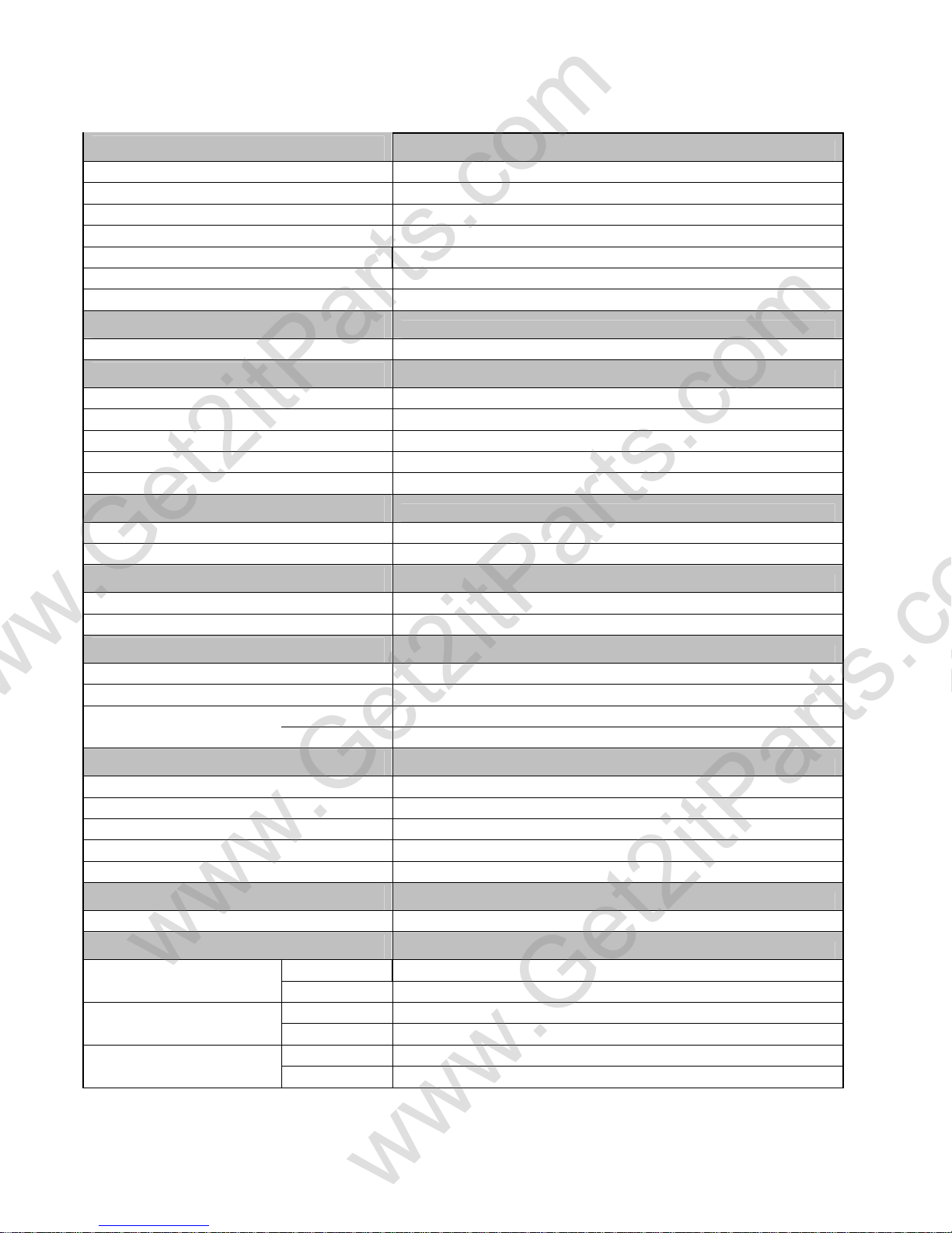
1.3 Specifications
Engine
Type Two cycle air cooled oil injected
Displacement 49.3cc
Bore / Stroke φ40.0 * 39.2mm
Compression - Ratio / Pressure 6.8 : 1 / 90-120psi
Torque / BHP 5.2N m @ 7000rpm / 1.5BHP
Estimated MPG 65mpg/795mpg
Starting Electrical with Kick starter back up
Transmission
Type Automatic (C.V.T. V-Belt)
Chassis
Overall Length 1830mm / 72.0"
Overall Width 650mm / 25.6"
Overall High 1100mm / 43.3"
Wheel Base 1260mm / 49.6"
Dry Weight 82kg / 180.7lb
Suspension
Front Telescopic Fork
Rear Unit Swing Arm / Single Shock
Brakes
Front Hydraulic Disc
Rear Mechanical Drum
Tires
Front 120/90-10
Rear 130/90-10
Tire Pressure
Front Front 18psi / 1.25kg/cm2 (Cold)
Rear
Carburetor
Make/Size
Main Jet
Pilot Jet
Air Mixture Adjustment
Idle Speed
Battery
Jell Acid (Maintenance Free)
Fluids
Fuel
2 Cycle Oil
Transmission
Type Unleaded Gasoline 89 octane
Volume 5.5liters / 1.5gal
Type
Volume 1.1 liters / 1.2qts
Type SAE 80/90 weight
Volume 100cc / 3.4oz
Rear 25psi / 1.75kg/cm2 (Cold)
Mikuni 18mm (Manual Coke)
85mm
20mm
Back out ¾ - 1¼ turns
Idle 1700 - 1900rpm
12V-4AH/5AH - GTX5L-BS
High grade synthetic 2 cycle injector oil
Beamer Rev-2.0.2 Page 5 of 55 11/21/2005
Page 6
www.Get2itParts.com
www.Get2itParts.com
Spark Plug
NGK (recommended)
Nipendenso
Champion
Electrode Gap 0.6-0.7mm / 0.023"
GVWR
GAWR (Front)
GAWR (Rear)
Available Colors
*Subject to availability
BPR7HS
W22FRP-U
QL82YC
240kg. / 530lbs.
76kg. / 167lbs.
165kg. / 164lbs.
Red
Blue
Yellow
Black
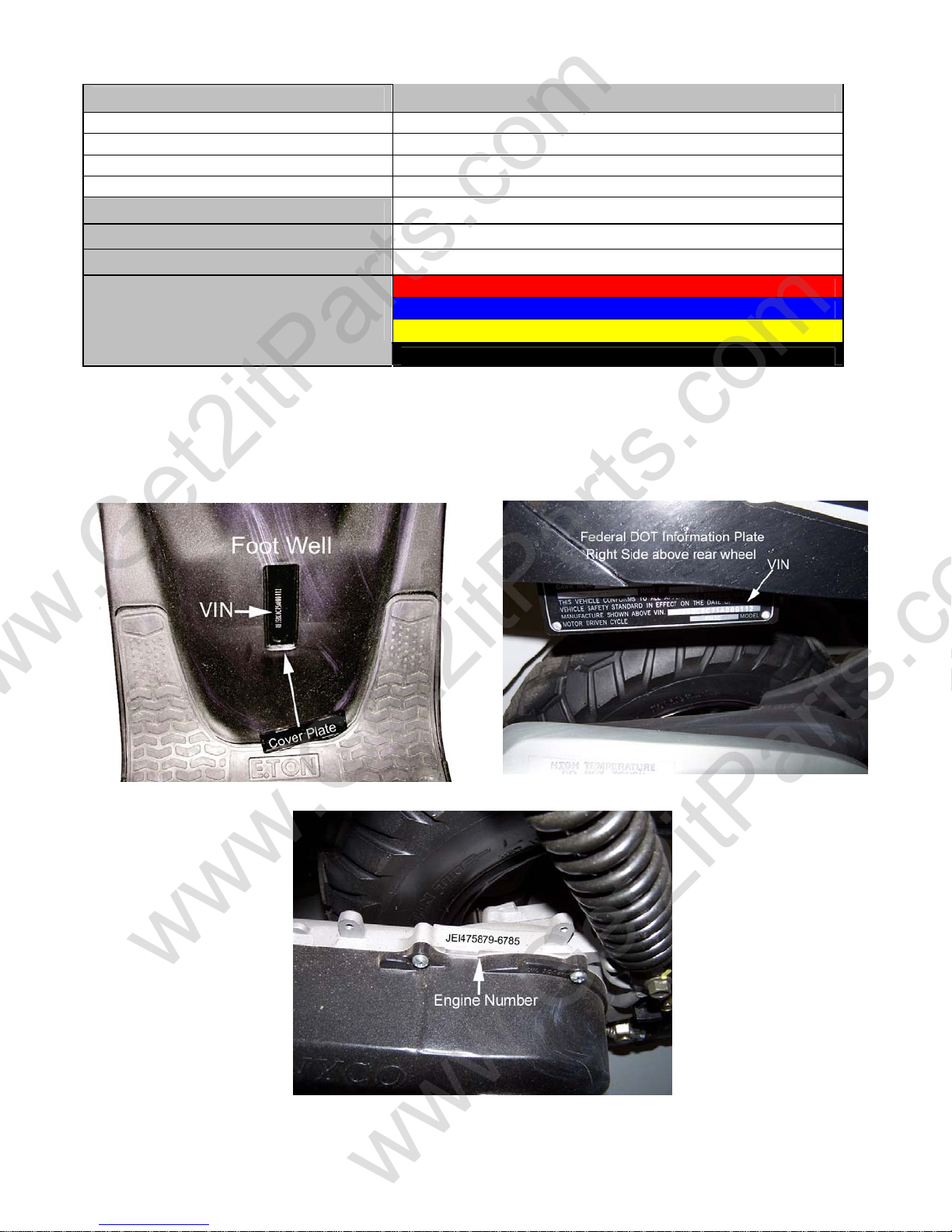
1.4 SERIAL NUMBER
The frame serial number is stamped on the front of the frame, at the front of the footrest plate.
The engine serial number is stamped on the left side of the engine crankcase.
Beamer Rev-2.0.2 Page 6 of 55 11/21/2005
Page 7
www.Get2itParts.com
www.Get2itParts.com
1.5 Standard Torque Values
ENGINE
¾ Cylinder head nut 28-30 N-m (20.7-22.1 lb./ft)
¾ Spark plug 12-19 N-m (8.9-14.0 lb./ft)
¾ Cylinder head bolt 20-30 N-m (14.8-22.1 lb./ft)
¾ Alternator bolt 8-12 N-m (5.9- 8.9 lb./ft)
FRAME
¾ Handlebar upper holder bolt 24-30 N-m (17.7-22.1 lb./ft)
¾ Steering shaft nut 50-60 N-m (36.9-44.3 lb./ft)
¾ Steering shaft bushing holder nut 24-30 N-m (17.7-22.1 lb./ft)
¾ Wheel rim bolt 18-25 N-m (13.3-18.4 lb./ft)
¾ Tie rod lock nut 35-43 N-m (25.8-31.7 lb./ft)
¾ King pin nut 30-40 N-m (22.1-29.5 lb./ft)
¾ Handlebar lower holder nut 40-48 N-m (29.5-35.4 lb./ft)
¾ Front wheel bolt 24-30 N-m (17.7-22.1 lb./ft)
¾ Front axle nut 55-65 N-m (40.6-47.9 lb./ft)
¾ Front brake arm nut 4-7 N-m (3.0- 5.2 lb./ft)
¾ Rear brake arm nut 7-12 N-m (5.2- 8.9 lb./ft)
¾ Rear axle nut 60-80 N-m (44.3-59.0 lb./ft)
¾ Rear wheel bolt 24-30 N-m (17.7-22.1 lb./ft)
¾ Exhaust muffler mounting bolt 30-35 N-m (22.1-25.8 lb./ft)
¾ Engine hanger bolt 24-30 N-m (17.7-22.1 lb./ft)
Beamer Rev-2.0.2 Page 7 of 55 11/21/2005
Page 8
www.Get2itParts.com
www.Get2itParts.com
2. MAINTENANCE
2.1 MAINTENANCE DATA
2.2 MAINTENANCE SCHEDULE
2.3 FUEL TUBE
2.4 THROTTLE OPERATION
2.5 THROTTLE CABLE ADJUSTMENT
2.6 AIR CLEANER
2.7 SPARK PLUG
2.8 IDLE SPEED
2.9 BRAKE SYSTEM
2.10 WHEELS AND TIRES
2.11 STEERING SYSTEM
2.12 GEAR OIL
2.1 MAINTENANCE DATA
SPECIFICATION
SPARK PLUG:
SPARK PLUG GAP: 0.6-0.7 mm
RECOMMENDED SPARK PLUGS: NGK BPR7HS
THROTTLE LEVER FREE PLAY: 5-10 mm
IDLE SPEED: 1600±100 rpm
BRAKE LEVER FREE PLAY: 15-25 mm
TIRES:
FRONT TIRE SIZE 120/90-10
REAR TIRE SIZE 130-90-10
FRONT/REAR TIRE PRESSURE 2.5± 0.3 kgf/cm2
TORQUE VALUES
SPARK PLUG 12-19 N-m
TIE-ROD LOCK NUT 35-43 N-m
LUBRICATION:
ENGINE OIL JASO FC Grade or same degree oil
GEAR LUBRICATION OIL SAE 40
Beamer Rev-2.0.2 Page 8 of 55 11/21/2005
Page 9
www.Get2itParts.com
www.Get2itParts.com
2.2 MAINTENANCE SCHEDULE
The maintenance intervals in the follow table are based upon average riding conditions. Riding in
unusually dusty areas may require more frequent servicing. E-TON recommends that all maintenance
and inspections be performed ONLY by a qualified and fully trained technician.
Fuel Line I
Throttle Operation I I I
Air Filter system &
Element
Spark Plug I R
Carburetor Idle Speed I I I
Brake Shoe Wear I I I
Brake System I I
Nut, Bolt, Fastener I I
Wheels & Wheel Nuts I I
Steering System
Suspension System I I
C.V.T. Air Filter C R
Air Induction Reed Valve I C/R
Transmission Gear Oil I R
Note –
I: Inspect and Clean, Adjust, Lubricate, or Replace (if necessary)
C: Clean
L: Lubricate
R: Replace
INITIAL
SERVICE
(First week) (Every 30 operating
I C R
REGULAR SERVICE
days)
I
EVERY
YEAR
I
I
I
I
2.3 FUEL TUBE
Inspect the fuel lines for deterioration, damage, or
leaks, and replace if necessary.
2.4 THROTTLE OPERATION
Inspect for smooth throttle lever full opening and
automatic full closing in all steering positions.
Inspect for deterioration, damage, or kinking
in the throttle cable. Replace if necessary.
Check the throttle lever. Free play is 5-10 mm at the tip
of the throttle lever.
Disconnect the throttle cable at the upper end.
Lubricate the cable with commercially available lubricant to prevent premature wear.
Beamer Rev-2.0.2 Page 9 of 55 9/21/2006
Page 10
www.Get2itParts.com
www.Get2itParts.com
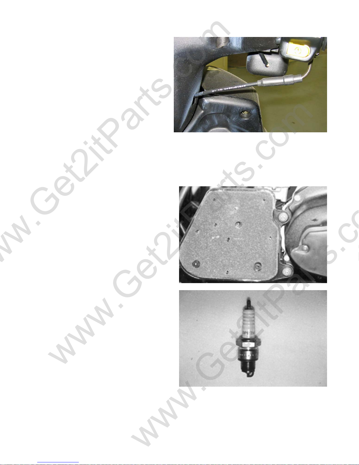
2.5 THROTTLE CABLE
ADJUSTMENT
Slide the rubber adjuster cap off the throttle
housing, loosen the locking nut, and adjust the
free play of the throttle lever by turning the
adjuster on the throttle housing. Inspect the free
play of the throttle lever.
This free play should be 5-10mm.
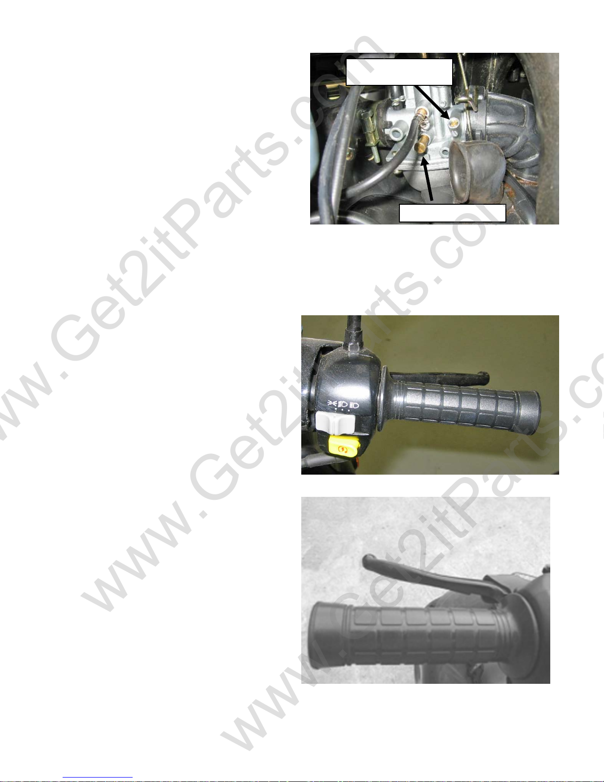
2.6 AIR CLEANER
Unscrew the air cleaner cover screws.
Pull out the air filter element from the air cleaner
case. Wash the element in non-flammable solvent.
Squeeze out the solvent thoroughly.
Let it dry. Soak the filter element in gear oil and
then squeeze out the excess oil.
Install the element into the air cleaner carefully.
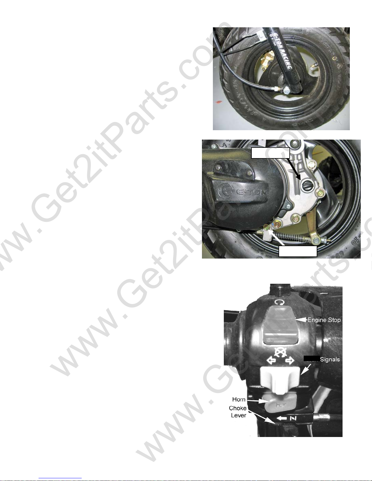
2.7 SPARK PLUG
The spark plug is located at the front of the
engine. Disconnect the spark plug cap and remove
the spark plug. Check the spark plug electrodes
for wear. Change the spark plug if the electrodes
and insulator tip appear unusually fouled or
burned.
Discard the spark plug if there is apparent wear or
if the insulator is cracked or chipped.
The spark plug gap should be set to 0.6-0.7mm.
With the sealing washer attached, thread the spark
plug in by hand to prevent cross threading.
Torque the spark plug to 12-19 N-m.
Beamer Rev-2.0.2 Page 10 of 55 11/21/2005
Page 11
j
www.Get2itParts.com
www.Get2itParts.com
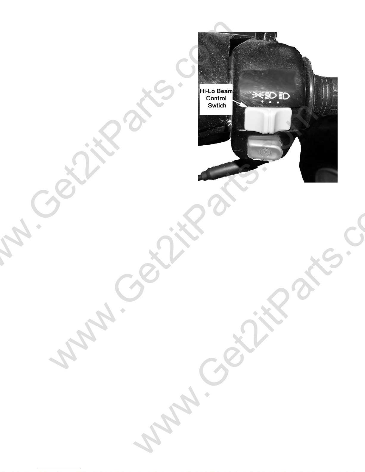
2.8 IDLE SPEED
Connect a tachometer.
Warm up the engine for at least 10 minutes.
Turn the idle-speed adjust screw on the carburetor
to obtain the idle speed. "Turn in" (clockwise)
to get higher speed. "Turn out" (counter clockwise)
to get lower speed.
IDLE SPEED: 1600±100 rpm
2.9 BRAKE SYSTEM
Inspect the front brake lever and cable for
excessive play or other damage.
Replace or repair if necessary.
Measure the free play of the brake lever at the end
of the brake lever.
The standard of free play is 15-25 mm.
Inspect the rear brake lever and cable for
excessive play or other damage.
Replace or repair if necessary.
Measure the free play of the rear brake lever at
the end of the lever. The standard is 15-25 mm.
Adjust the free play of the rear brake lever by
turning the adjuster on the rear axle.
Air Mixture
ustment Screw
Ad
Idle Adjustment Screw
Beamer Rev-2.0.2 Page 11 of 55 11/21/2005
Page 12
t
www.Get2itParts.com
www.Get2itParts.com
2.10 WHEELS AND TIRES
Inspect the tire surfaces for cuts, nails, or other sharp
objects. Check the tire pressure at cold tire condition.
The standard tire pressure is 2.5±0.3 kgf/cm2
2.11 GEAR OIL
Transmission gear oil needs to be changed every year
or after every 3000 miles of service.
The drain bolt is located at the rear of engine.
Remove the drain bolt and loosen the fill bolt to drain
the transmission gear box.
Inspect the drained oil for foreign materials. If the oil
contains a high concentration of metal shavings or
powder, disassemble the transmission for further
inspection.
Reinstall the drain bolt and refill the gear box with
100cc
/ 3.4oz of SAE 80-90 Gear Oil
Note: for best results, drain the transmission while
the engine is warm.
Fill Plug
Drain Bol
2.12 ENGINE STOP SWITCH
The engine stop switch is located beside the left handle bar.
In an emergency, pushing this switch will stop the engine.
The stop switch must be place in the on position, the top of the
switch pressed down, for the engine to start.
If your engine fails to start, check the switch.
Beamer Rev-2.0.2 Page 12 of 55 11/21/2005
Page 13
www.Get2itParts.com
www.Get2itParts.com
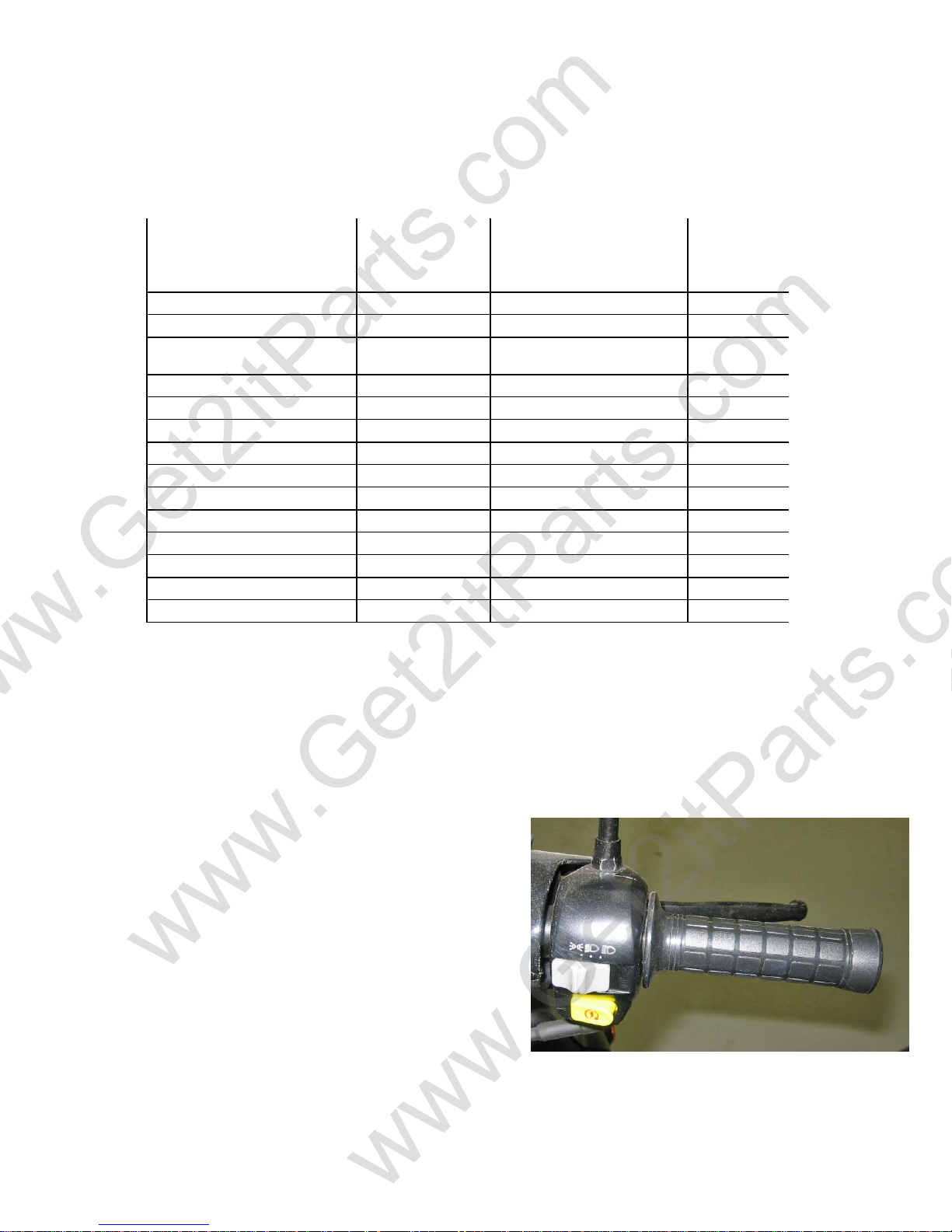
2.13 HIGH-LOW BEAM CONTROLLER
This controller is located beside right handle bar and
controls the headlight intensity setting.
When the switch is placed in the full right position, the
headlights are set to illuminate at 100% intensity. In the
center position the headlight will illuminate at 60%
intensity. Placed in the far left position, the headlights
will be off.
NOTE: It is recommended that you have the headlight
on at all times when operating the vehicle to improve
your visibility to other traffic.
Beamer Rev-2.0.2 Page 13 of 55 11/21/2005
Page 14
www.Get2itParts.com
www.Get2itParts.com
3. ENGINE REMOVAL AND INSTALLATION
3.1 ENGINE REMOVAL
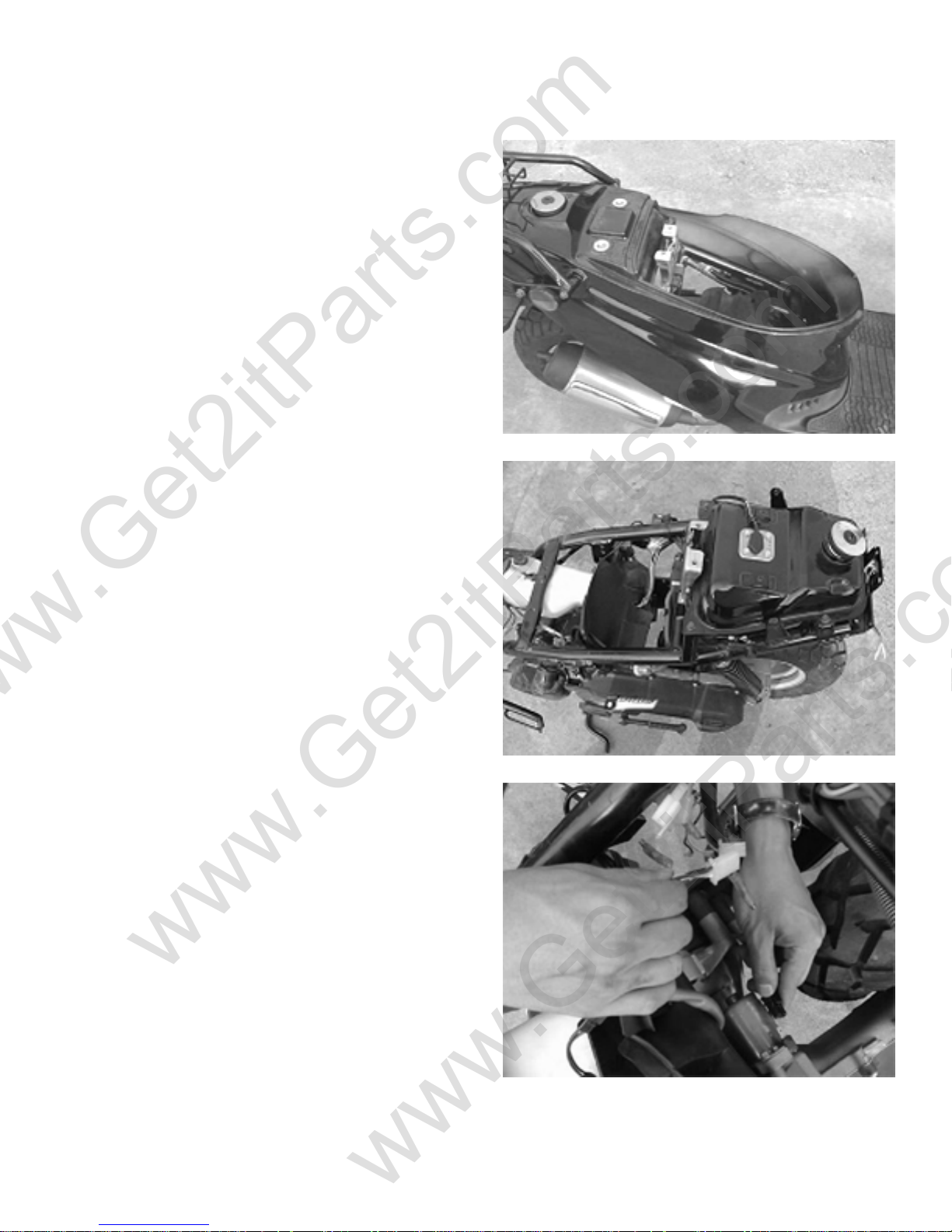
Remove the seat, helmet box, and body cover.
(See chapter 10 for complete instructions)
Disconnect oil tube, fuel tube, and vacuum line tube.
Disconnect the wires of the A/C generator and the
starter motor.
Beamer Rev-2.0.2 Page 14 of 55 11/21/2005
Page 15
www.Get2itParts.com
www.Get2itParts.com
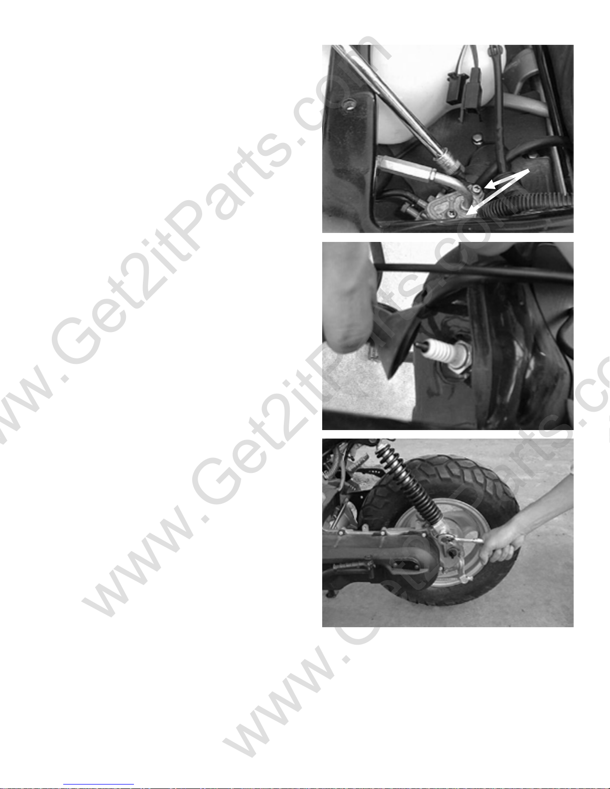
Disconnect the wires of the carburetor and the
throttle cable.
Remove the cap from the spark plug.
Remove the bolt at the low end of the rear shock.
Beamer Rev-2.0.2 Page 15 of 55 11/21/2005
Page 16
www.Get2itParts.com
www.Get2itParts.com
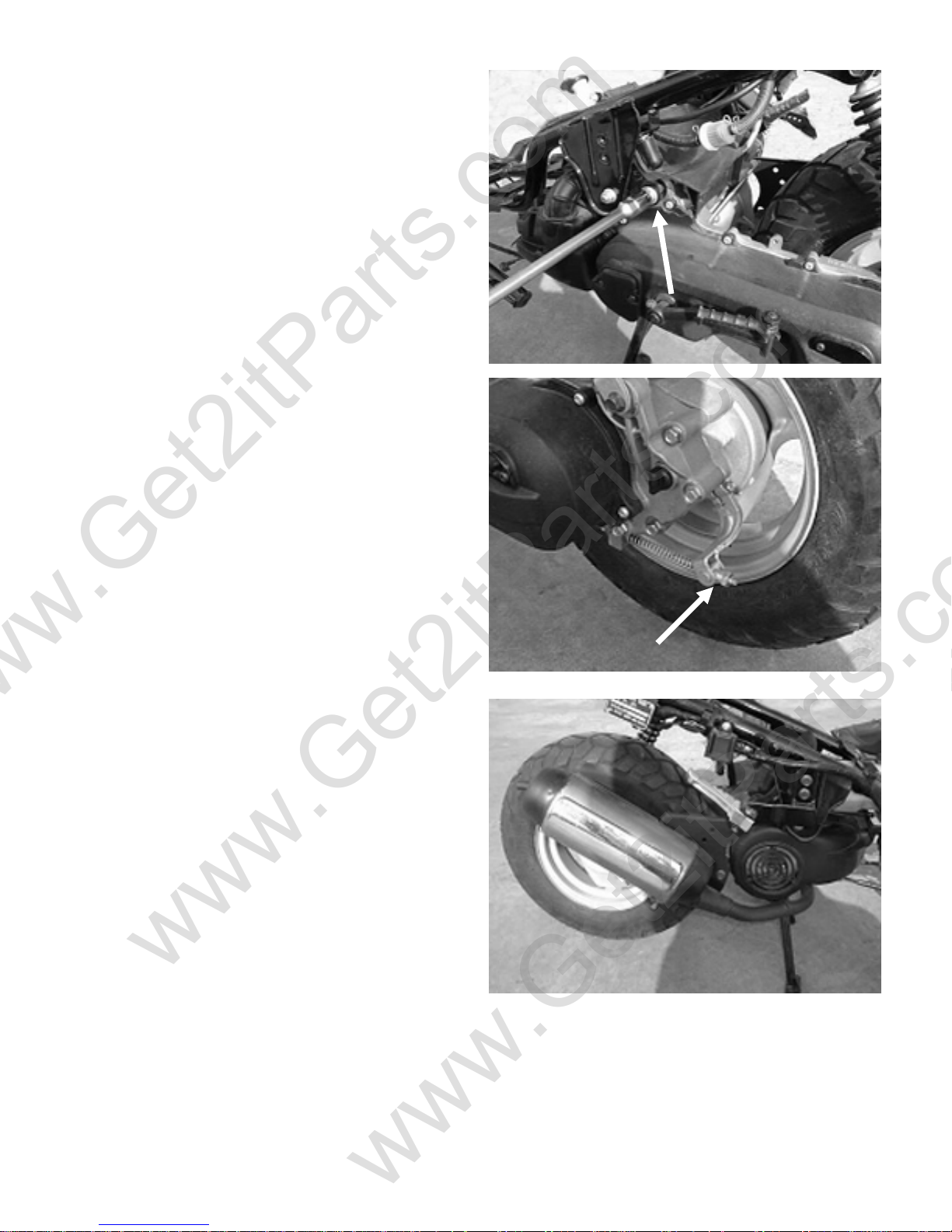
Remove the engine hanger nut.
Remove the rear brake cable adjusting nut.
Pull the engine out from the frame.
3.2 ENGINE INSTALLATION
Install engine in reverse order of disassembly.
Torque value:
M8 nut 15 - 22 lbf-ft
M10 nut 22 - 29 lbf-ft
M12 nut 36 – 43 lbf-ft
After installing the engine, check the parts below:
o All connections (A/C generator,
starter motor, etc)
o Carburetor throttle cable
o Rear brake cable
o Oil tubes and fuel tubes
Beamer Rev-2.0.2 Page 16 of 55 11/21/2005
Page 17
www.Get2itParts.com
www.Get2itParts.com
4. ENGINE FUEL SYSTEM
4.1 TROUBLESHOOTING
ENGINE WILL NOT START
ENGINE IDLES UNSTEADILY, STALLS,
OR RUNS POORLY
LEAN MIXTURE
¾ NO FUEL IN TANK
¾ NO FUEL IN CYLINDER
¾ TOO MUCH FUEL INTO CYLINDER
¾ NO SPARK AT PLUG
¾ AIR CLEANER CLOGGED
¾ IMPROPER ADJUSTMENT OF THE
IDLE SPEED SCREW AT CARBURETOR
¾ IGNITION MALFUNCTION
¾ FUEL/AIR MIXTURE RATIO TOO LEAN OR
TOO RICH
¾ AIR CLEANER DIRTY
¾ INSULATOR LEAKS
¾ FUEL TANK CAP BREATHING HOLE
CLOGGED
¾ CARBURETOR FUEL JET CLOGGED
¾ FUEL TANK CAP BREATHING HOLE
CLOGGED
¾ FUEL FILTER CLOGGED
¾ FUEL FLOWS IN THE TUBE IRREGULARLY
¾ FLOAT LEVEL IN CARBURETOR TOO LOW
RICH MIXTURE
Beamer Rev-2.0.2 Page 17 of 55 11/21/2005
¾ FLOAT NEEDLE VALVE IN CARBURETOR
FAULTY
¾ FLOAT LEVEL TOO HIGH
¾ AIR DUCT IN CARBURETOR IS CLOGGED
¾ AIR CLEANER DIRTY
Page 18
r
r
www.Get2itParts.com
www.Get2itParts.com
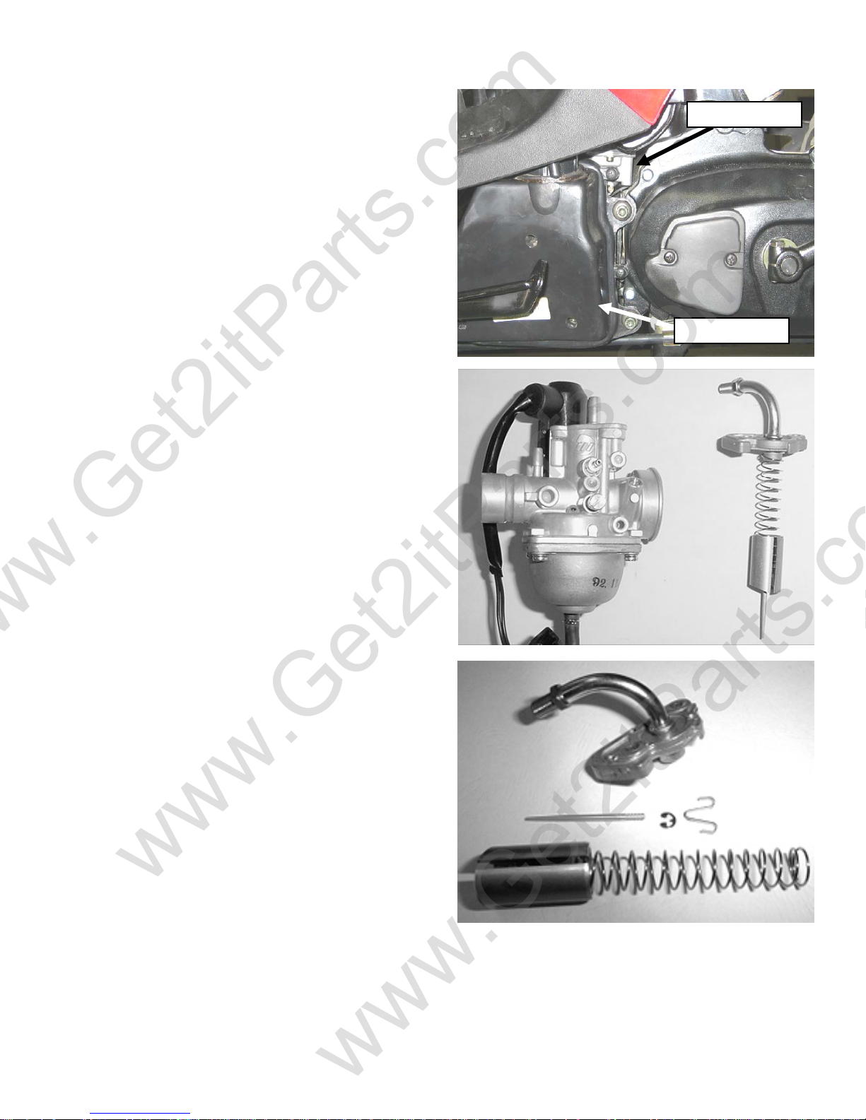
4.2 CARBURETOR
REMOVAL
Remove the air cleaner.
Disconnect the fuel line and auto-choke electric wire.
Unscrew the intake pipe mounting bolts at the
carburetor, and then remove the carburetor.
Note: Before removing carburetor, you must shut the
fuel flow off.
Remove the carburetor cap.
Remove the throttle cable from the throttle valve
while depressing the throttle valve spring.
Remove the needle clip retainer, the jet needle, and
needle clip. Inspect the throttle valve and jet needle
surface for wear, scratches, or dirt.
Carbureto
Air Cleane
Beamer Rev-2.0.2 Page 18 of 55 11/21/2005
Page 19
t
t
www.Get2itParts.com
www.Get2itParts.com
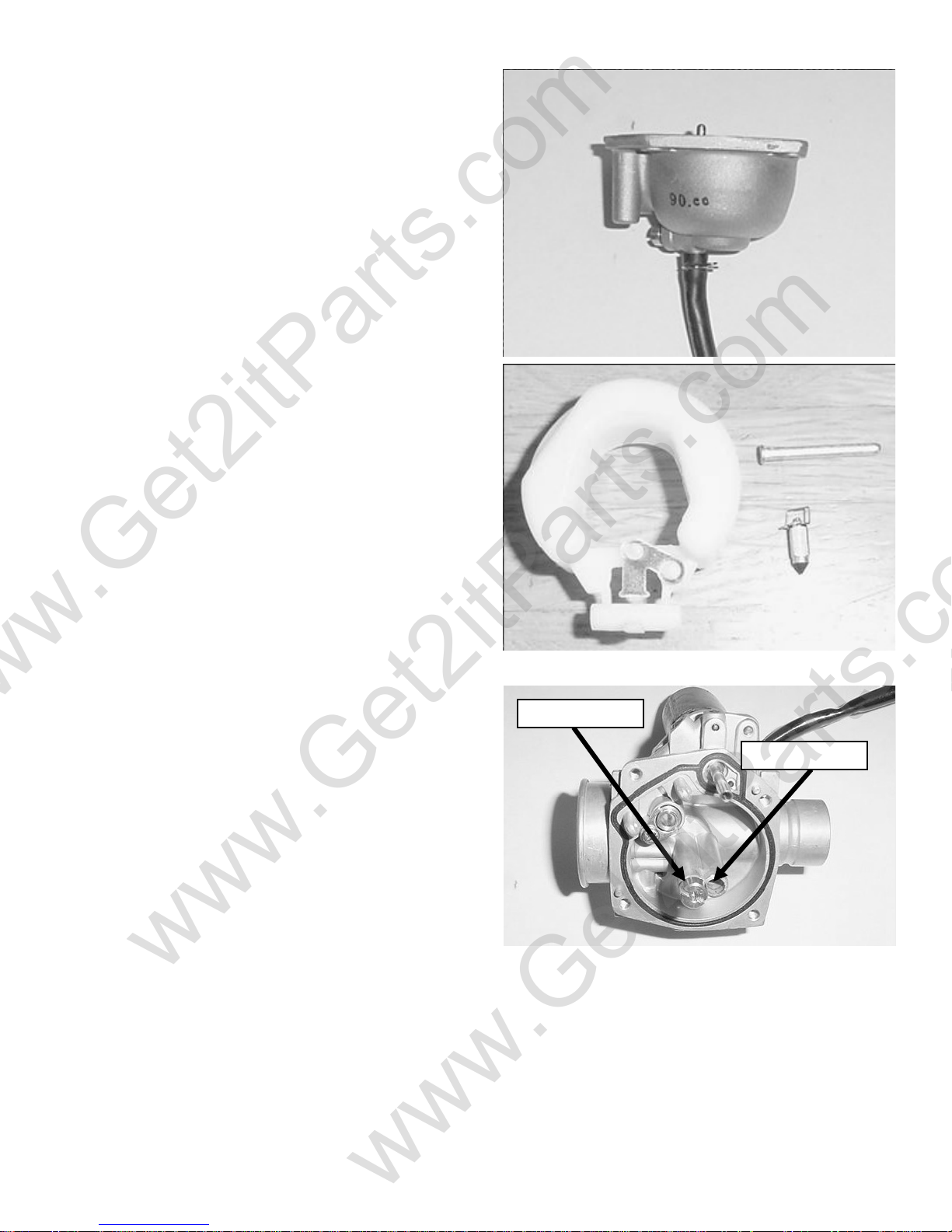
DISASSEMBLY
Unscrew the float chamber screws and remove the
float chamber.
Disassemble the float arm pin, float and float needle
valve.
Inspect the seat of the float needle valve for wear or
damage.
Disassemble the idle jet, main jet, idle speed
adjustment screw, and idle mixture adjustment screw.
Inspect all jets and screws for wear or damage.
Clean the passages and jets with compressed air.
ASSEMBLY
Clean all parts in solvent and blow it dry with
compressed air. Assembly is the reverse order of
disassembly.
Main Je
Pilot Je
Beamer Rev-2.0.2 Page 19 of 55 11/21/2005
Page 20
www.Get2itParts.com
www.Get2itParts.com
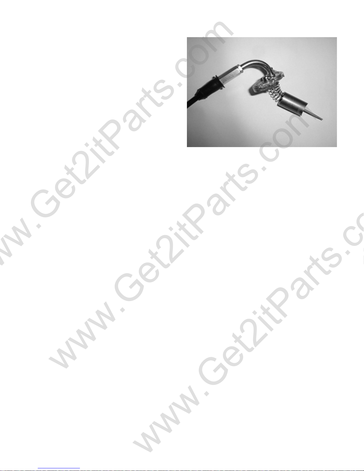
THROTTLE VALVE ASSEMBLY
Install the needle clip on the jet needle.
Install the jet needle into the throttle valve.
Assemble the throttle cable, spring, and throttle
valve. Align the throttle valve groove with the idle
speed adjust screw and install the carburetor cap to
the carburetor.
Beamer Rev-2.0.2 Page 20 of 55 11/21/2005
Page 21
www.Get2itParts.com
www.Get2itParts.com
5. ENGINE LUBRICATION AND COOLING SYSTEM
5.1 TROUBLESHOOTING
NOT ENOUGH OIL GIVEN TO ENGINE
¾ THE OIL LEVEL IN THE OIL TANK IS
TOO LOW.
¾ OIL TUBES NOT FIXED PROPERLY.
¾ OIL LEAKING FROM TUBE ENDS.
¾ OIL TUBES BROKEN.
¾ OIL TUBES CLOGGED.
¾ OIL PUMP BROKEN.
INSUFFICIENT OIL LEVEL IN TANK
ENGINE OVERHEATS
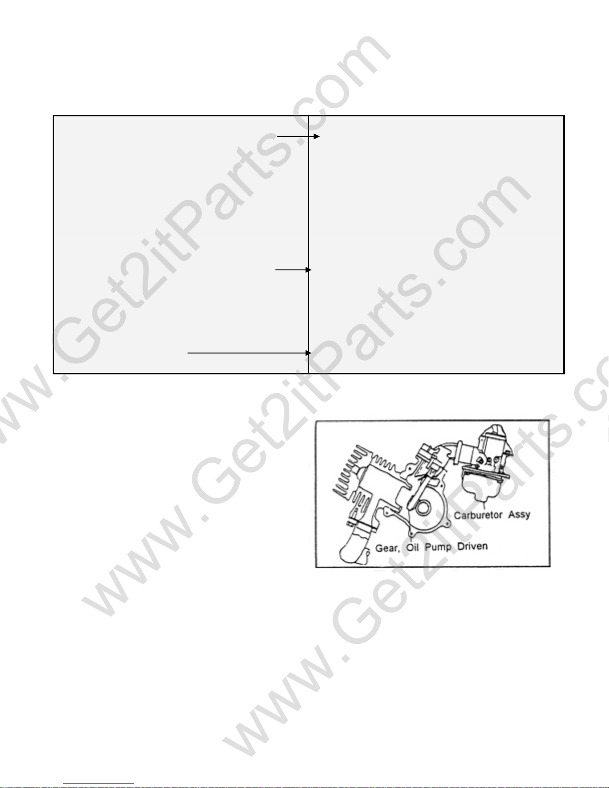
5.2 ENGINE LUBRICATION SYSTEM
The gears of the oil pump are driven by the
engine crankshaft. Pump gears rotate the plunger
shaft in the oil pump. This shaft sends the
lubricating oil into the crankcase to mix with the
mixture of air-fuel flow evenly. The oil enters and
covers the cylinder inner wall, piston surface, and
piston rings.
¾ EXTERNAL OIL LEAKS
¾ WORN CYLINDER HEAD GASKET
¾ WORN PISTON RINGS
¾ PUMP NOT ADJUSTED PROPERLY
¾ OIL QUALITY IS BAD
5.3 CAUTION: Fuel/Oil Ratio
Having enough oil in the engine is very important.
If the oil quantity is too low, the engine will be seriously scratched, likely seize, and possibly not work
again.
When the cylinder wall is scored or scratched, replace the piston, piston rings, and cylinder together.
Check the combustion system and lubrication system carefully.
Beamer Rev-2.0.2 Page 21 of 55 11/21/2005
Page 22
www.Get2itParts.com
www.Get2itParts.com
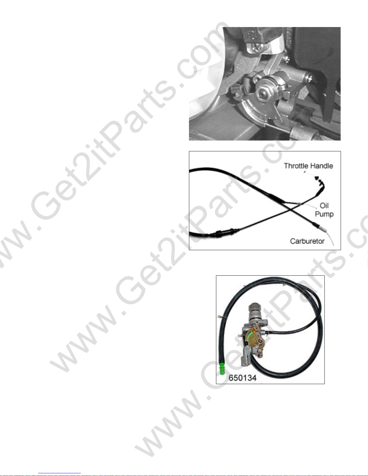
5.4 OIL PUMP
The quantity of oil that is delivered from oil pump
increases with the engine speed and carburetor
throttle width opening. The oil pump is located
under the right side of the engine and connected by
a control cable from the throttle. The throttle cable
assembly splits into two cables with one end
controlling the carburetor throttle cylinder and the
other end controlling the quantity of oil delivered
by the oil pump.
DISASSEMBLE OIL PUMP
Remove the helmet box.
Disconnect the input and output oil tube.
Unscrew the oil pump fixing bolts.
Remove the oil pump.
INSPECT OIL PUMP
Check the matching side in the crankcase.
Inspect the oil pump body.
Inspect the gear part for damage.
Inspect the O-ring for any leaks.
ASSEMBLE OIL PUMP
Apply grease on the O-ring and gear parts.
Insert the oil pump into the engine crankcase.
Fasten the fixing bolts.
Torque value is 6 – 9 lbf-ft.
Beamer Rev-2.0.2 Page 22 of 55 11/21/2005
Page 23
www.Get2itParts.com
www.Get2itParts.com
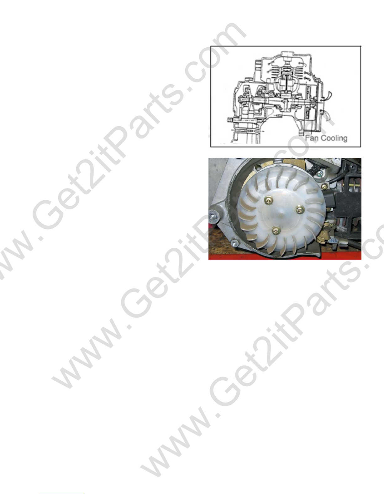
5.5 COOLING SYSTEM
The engine-cooling fan forces the air over the engine.
The cooling fan is on the right side of engine. The air is
forced to flow through cylinder fin and cylinder head.
This prevents the cylinder and piston from overheating.
Disassemble the engine fan cover and cylinder plastic
cover. Inspect the fan and cylinder fin. If the blades of
the fan are broken, replace with a new fan.
Beamer Rev-2.0.2 Page 23 of 55 11/21/2005
Page 24
www.Get2itParts.com
www.Get2itParts.com
6. ENGINE COMBUSTION SYSTEM
6.1 TROUBLESHOOTING
LOW COMPRESSION
HIGH COMPRESSION
EXCESSIVE NOISE
EXCESSIVE SMOKE
¾ HEAD GASKET LEAKING OR DAMAGED
¾ WARPED OR CRACKED CYLINDER HEAD
¾ CYLINDER OR PISTON RINGS WORN OUT
¾ EXCESSIVE CARBON BUILD-UP ON PISTON HEAD OR IN
COMBUSTION CHAMBER
¾ PISTON AND CYLINDER WORN OUT
¾ EXCESSIVE CARBON BUILD-UP
¾ CYLINDER OR PISTON RINGS WORN OUT
¾ IMPROPER INSTALLATION OF PISTON RINGS
¾ PISTON OR CYLINDER WALL SCORED OR
OVERHEATING
SCRA TCHED
¾ EXCESSIVE CARBON BUILD-UP ON THE PISTON OR
COMBUSTION CHAMBER
¾ ENGINE COOLING SYSTEM (FAN, CYLINDER COVER,
ETC.) WORKING IMPROPERLY
¾ OIL QUANTITY LOW
¾ WRONG IGNITION TIMING
Beamer Rev-2.0.2 Page 24 of 55 11/21/2005
Page 25
www.Get2itParts.com
www.Get2itParts.com
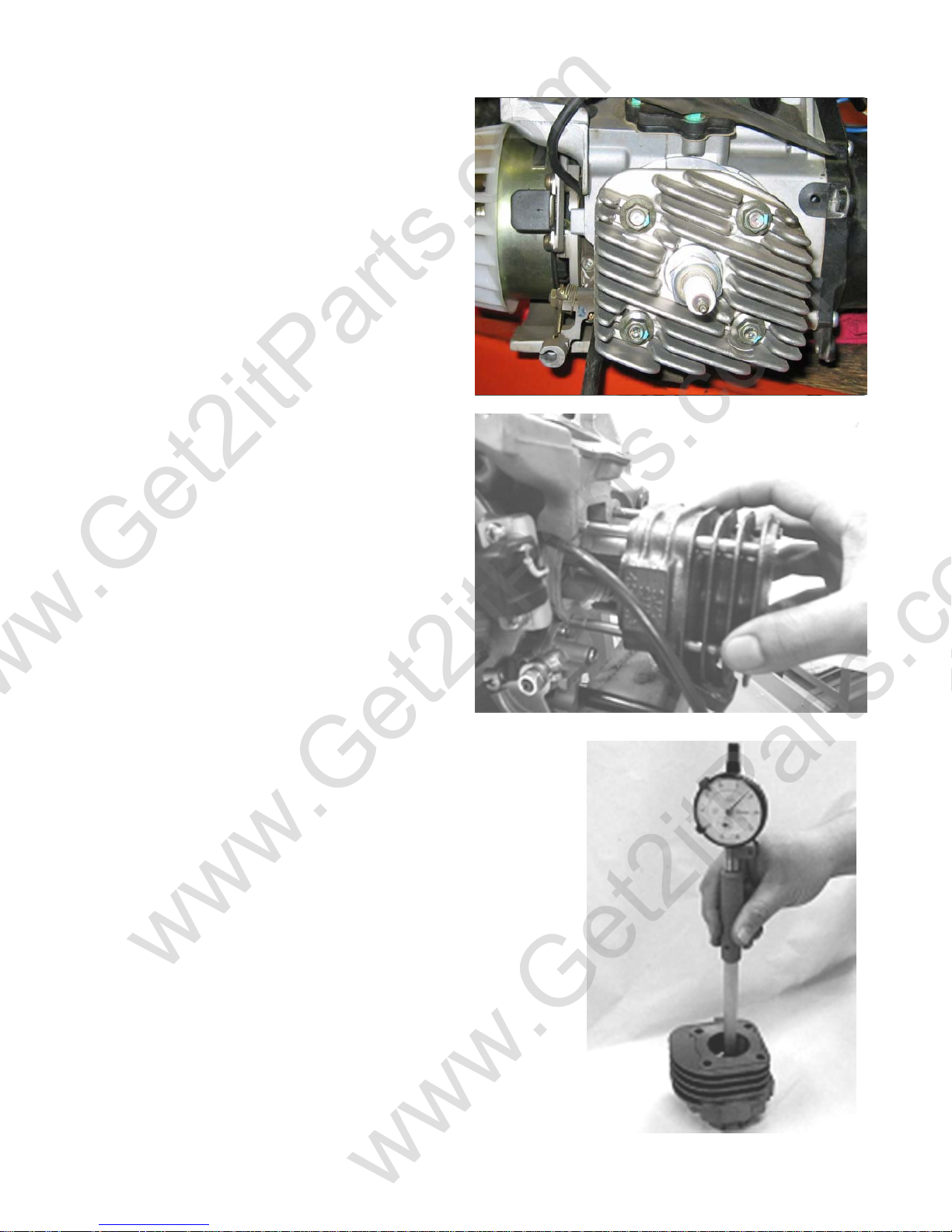
6.2 CYLINDER AND PISTON
REMOVAL
Remove the engine. (See chapter 3)
Disassemble the air cleaner and carburetor.
Remove the intake pipe mounting bolts.
Remove the cylinder bolt nuts.
Remove the cylinder head.
Remove the cylinder carefully, so the whole
piston is visible.
Remove one piston pin clip.
Remove the piston and piston pin.
Spread each piston ring and remove it.
Note: Don't let the clip drop into the engine
crankcase.
6.3 CYLINDER AND PISTON INSPECTION
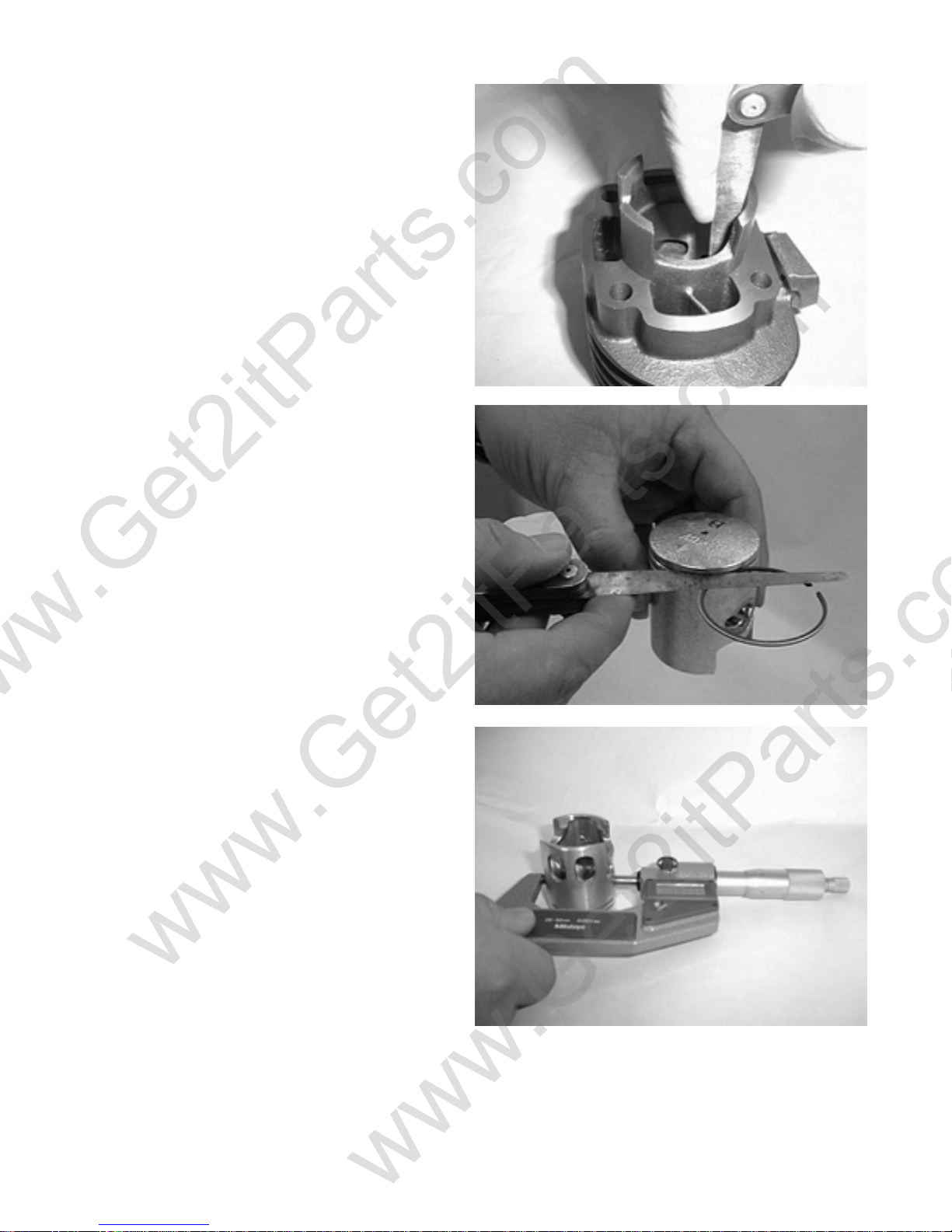
Inspect the cylinder bore for wear or damage.
Measure the cylinder inner diameter at three levels in the X- and
Y-axis.
Taper limit: 0.10 mm
Out of round limit: 0.10 mm
Check the cylinder head surface for signs of warping with a
straight edge and feeler gauge.
Service limit: 0.10 mm
Beamer Rev-2.0.2 Page 25 of 55 11/21/2005
Page 26
www.Get2itParts.com
www.Get2itParts.com
Insert each piston ring into the cylinder, and
measure the end gap.
Service limit: 0.5 mm
Measure the clearance between the ring and
groove.
Service limit: 0.09 mm
Measure the pistons outer diameter at 10 mm
above the bottom.
Service limit: 39.9 mm
Beamer Rev-2.0.2 Page 26 of 55 11/21/2005
Page 27
www.Get2itParts.com
www.Get2itParts.com
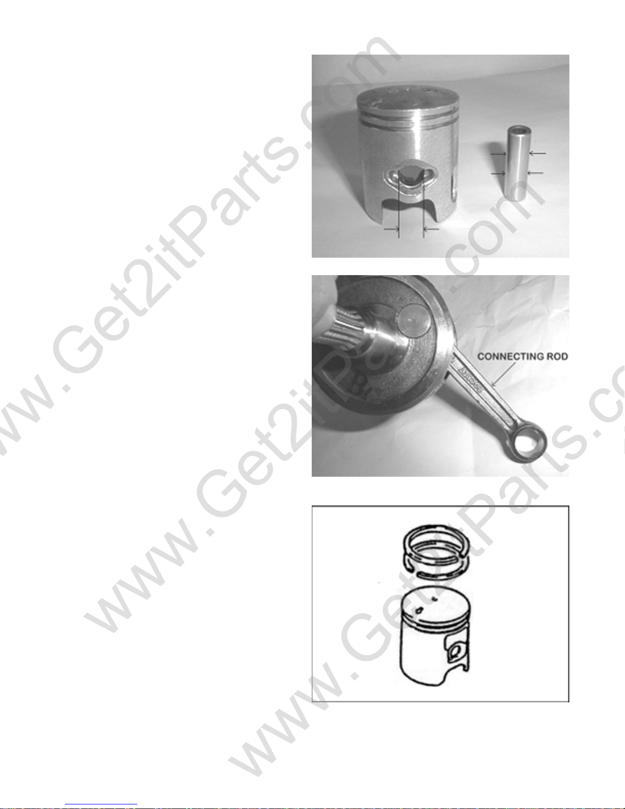
Measure the piston pin bore, and the piston pin
outer diameter.
Pin outer diameter Service limit: 10.04 mm
Pin bore Service limit: 9.96 mm
Measure the connecting rod small end inner
diameter with a small hole-gauge.
Service limit: 14.06 mm
6.4 INSTALLATION
Install the piston rings with the marks facing up.
Do not damage the piston rings by spreading the
ends too far.
Note: The piston ring gap must align with the ring
pin in the ring groove of piston.
Clean the cylinder gasket surface, being careful
not to drop any gasket material into the crankcase.
Apply some oil to the inside of the connecting rod
small end.
Install the piston, piston pin, and clip.
Install the piston with the arrow mark facing the
exhaust pipe.
Beamer Rev-2.0.2 Page 27 of 55 11/21/2005
Page 28
www.Get2itParts.com
www.Get2itParts.com
Do not align the piston pin clip end gap with the
piston cut-out.
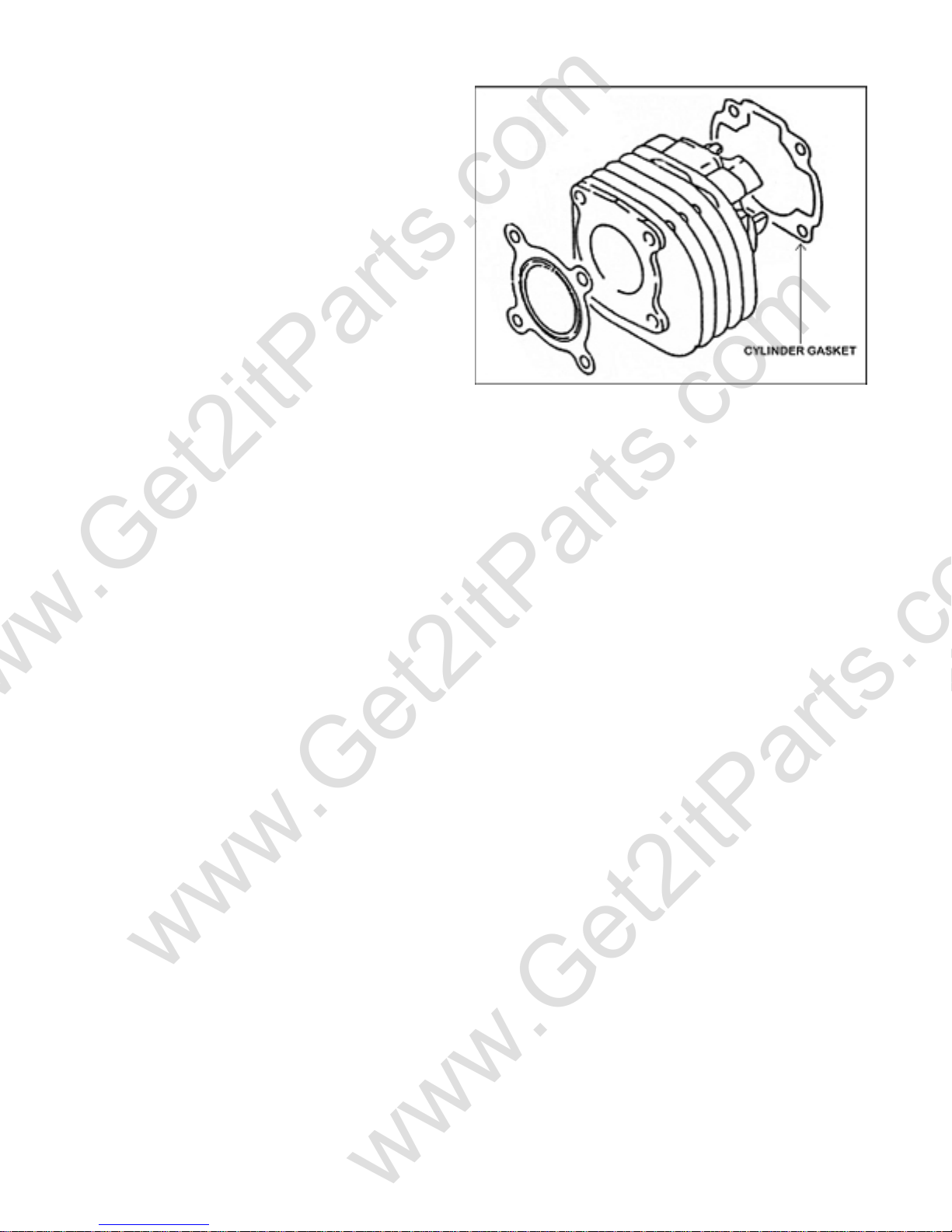
Install a new cylinder gasket.
Apply a thin coat of engine oil to the piston rings
and cylinder wall.
Install the cylinder, compressing the piston rings.
Replace the cylinder head gasket.
Install the cylinder head.
Tighten the cylinder-mounting bolt.
Torque: 20-30 N-m
Beamer Rev-2.0.2 Page 28 of 55 11/21/2005
Page 29
www.Get2itParts.com
www.Get2itParts.com
7. TRANSMISSION SYSTEM
7.1 TROUBLESHOOTING
Vehicle will not move after engine is started
Vehicle will not attain high speed
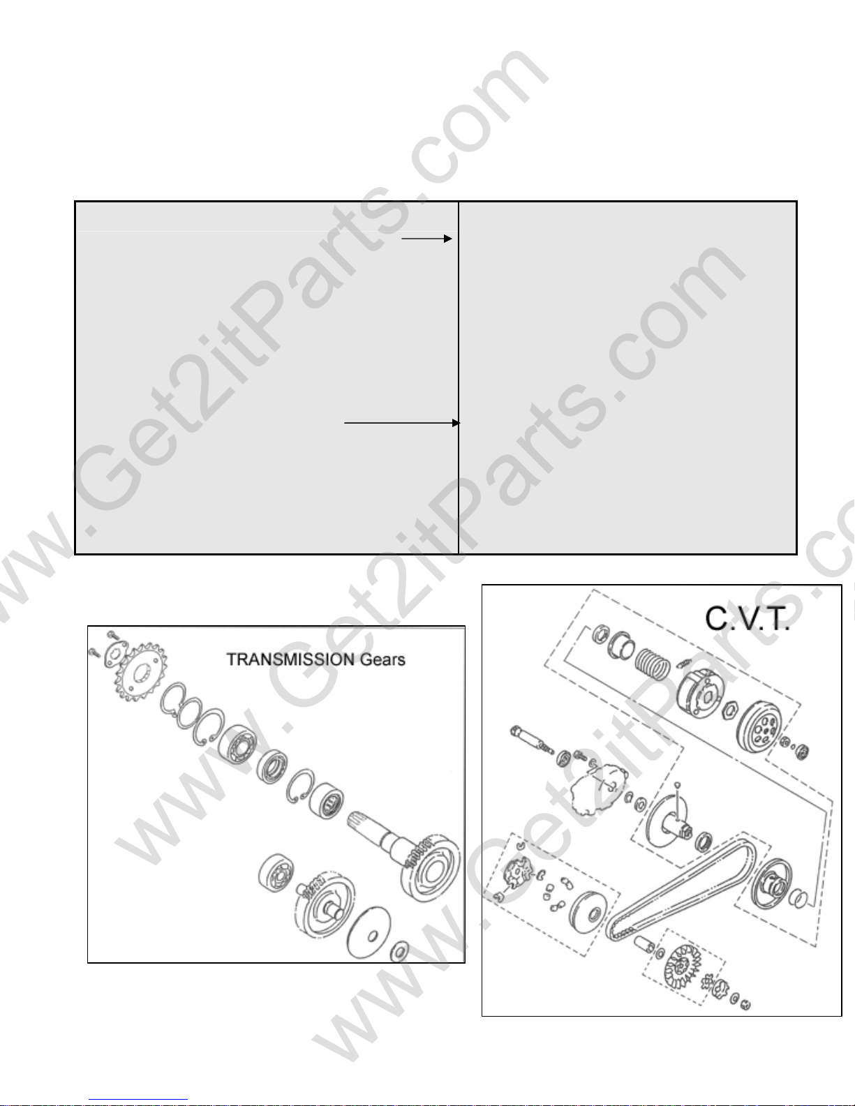
7.2 THE PARTS DRAWING OF
TRANSMISSION SYSTEM
¾ BELT WORN
¾ FRONT PULLEY WORN OR BROKEN
¾ CLUTCH LINING WORN
¾ BELT WORN
¾ ROLLERS WORN
¾ SPRING OF REAR PULLEY IS DISTORTED
¾ ELECTRONIC SPEED LIMITER EXCEDED
Beamer Rev-2.0.2 Page 29 of 55 11/21/2005
Page 30
www.Get2itParts.com
www.Get2itParts.com
7.3 TRANSMISSION POWER PATH
¾ The crankshaft torque drives the front pulley.
¾ The torque (drive) pulley turns the belt.
¾ The belt drives the rear (driven) pulley.
¾ The force is transmitted through the clutch shoe, clutch housing, and drive shaft.
¾ The drive shaft turns the idle gear in gearbox.
¾ Turning speed is reduced by the final-gear and transmitted to the rear-axle shaft to move rear
wheel.
Beamer Rev-2.0.2 Page 30 of 55 11/21/2005
Page 31
www.Get2itParts.com
www.Get2itParts.com
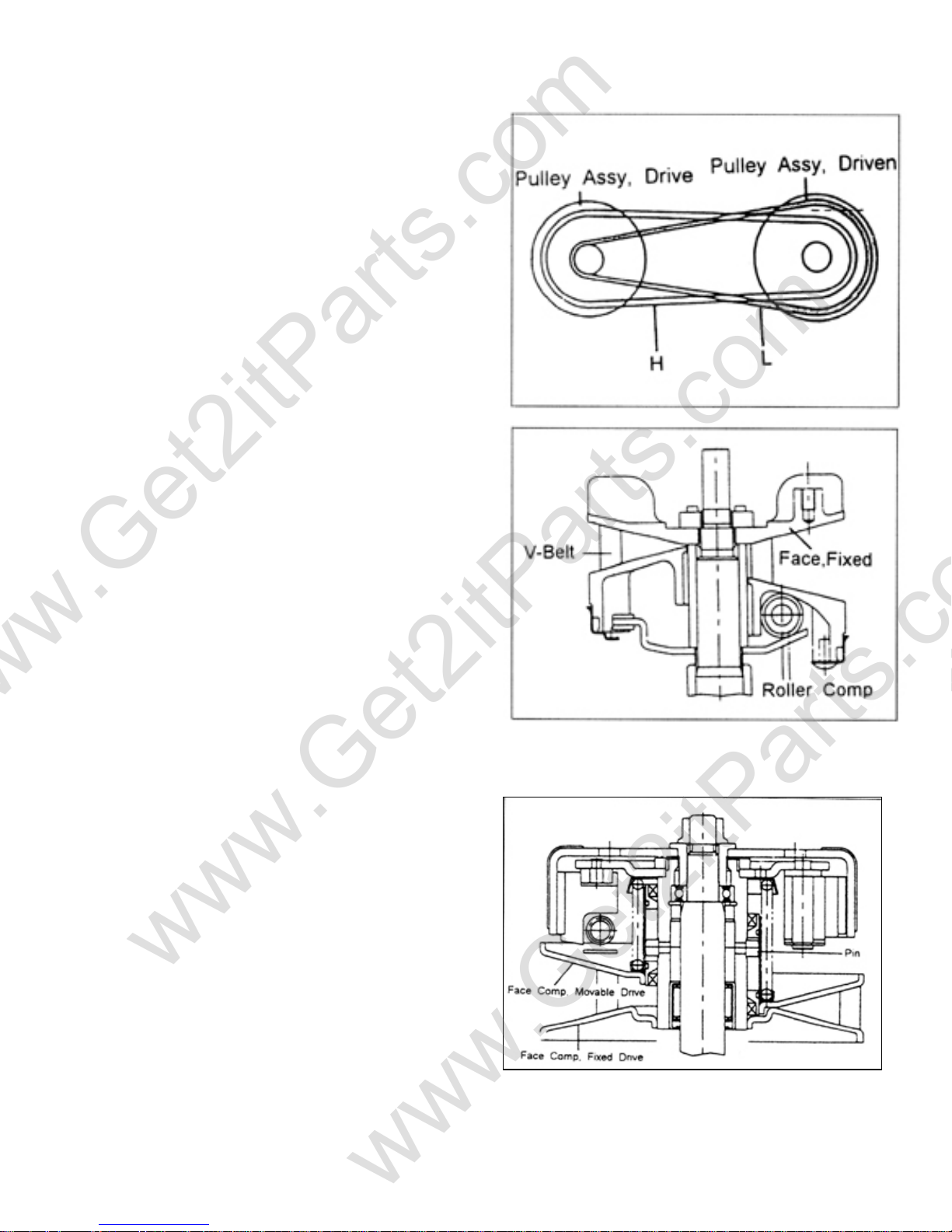
7.4 AUTOMATIC CONTINUOUS
VARIABLE TRANSMISSION
The transmission is a combination of an automatic
centrifugal clutch and a V-belt continuous variable
transmission, which can change the transmission ratio
automatically.
When the engine speed increases, the drive pulley
will push the belt by centrifugal force from the six
rollers.
Then, the pitch circle of belt in the drive pulley will
be larger.
The belt at the drive pulley is forced to move to the
center of the shaft, and then the radius of pitch circle
is decreased.
The transmission ratio is therefore altered by the
alteration of pitch circle's radius.
(In the drawing, "H" means high speed; "L" means
low speed)
7.5 CONTINUOUS VARIABLE
TRANSMISSION
V-Belt
The belt is made of rubber fiber. It is resistant to heat,
pressure, and abrasion. The inner side of the belt is toothed.
Drive Pulley
Due to increasing engine speed, the rollers push the
movable drive face by centrifugal force. Then, the
belt is pressed and enlarges its turning radius. The
aluminum fan is installed on the exterior of the fixed
drive face. It can reduce the belt temperature.
Driven Pulley
Because the revolving radius of the V-Belt at the
drive end is enlarged, the Face Comp Movable Drive
is squeezed out by the V-Belt at the driven end to
shorten the revolving radius.
Beamer Rev-2.0.2 Page 31 of 55 11/21/2005
Page 32
www.Get2itParts.com
www.Get2itParts.com
There is a Torque Cam on the Movable Drive Face.
The torque Cam is loaded from the outside. When the outside load is higher than the engine's output, the
pulley of the fixed shaft and belt slip to make the Movable Drive Face move along the inner side of the
cam and compensate to increase to high torque (toward low speed) and make the engine maintain
smooth running with original revolution.
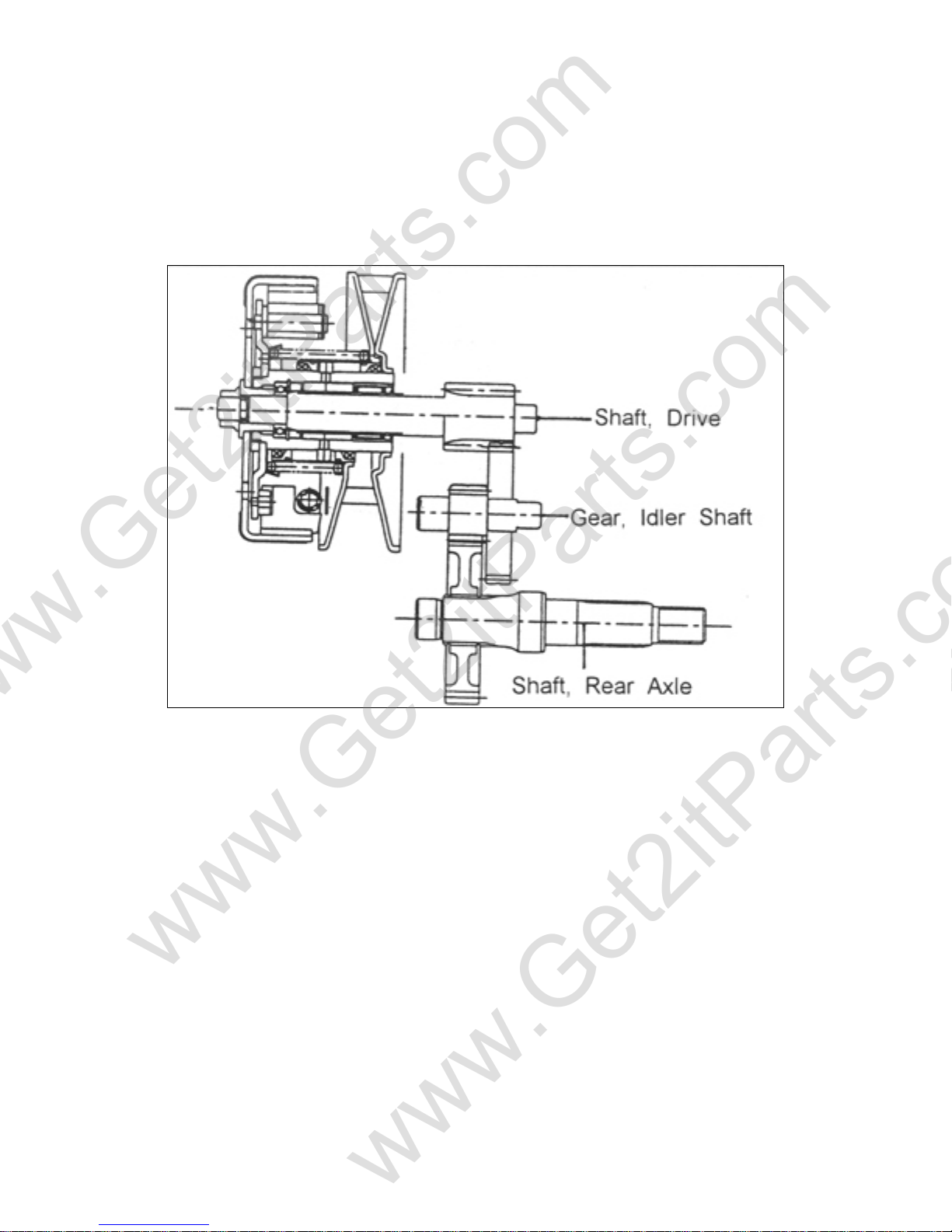
7.6 TRANSMISSION BOX
The torque received by the drive shaft will be transmitted by the speed reduction of two sets to the rear
axle shaft.
The first gear ratio is 36/13.
The second gear ratio is 48/12.
DISASSEMBLING THE TRANSMISSION BOX
1. Remove the exhaust pipe. Torque value: M6: 7 - 9 lbf-ft
M10: 25 – 29 lbf-ft
2. Unscrew rear axle nut and remove rear wheel.
3. Unscrew oil-drain bolt at the bottom of crankcase.
4. Let the oil flow out from transmission box.
5. Unscrew six bolts of transmission box cover.
6. Remove the transmission cover.
7. Remove the gears from transmission box.
Lubricating oil is SAE 80/90, 100cc/3.4oz.
Beamer Rev-2.0.2 Page 32 of 55 11/21/2005
Page 33
www.Get2itParts.com
www.Get2itParts.com
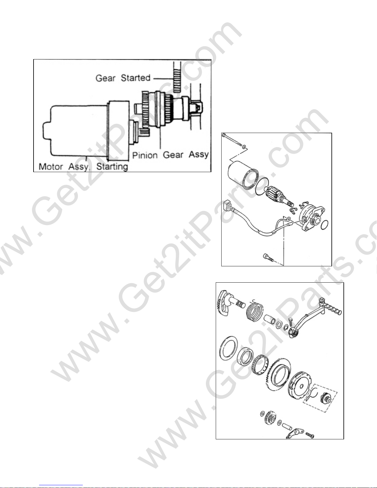
7.7 ELECTRIC STARTER MOTOR
The Starter Motor is installed on the upper
side of engine.
The starter motor can only be activated
when the left hand brake is applied and
the engine stop switch is in the run
position.
7.8 KICK STARTER
The kick-starter arm is on the left side of engine. When the
kick-starter arm is kicked, the gear of the starter shaft will
drive the kick-starter to turn the crankshaft to start the
engine.
After the engine is started, the kick-starter will stop the
transfer of power to the kick-starter driven gear.
When the kick-starter lever is released, the kick-starter gear
will go back to its original position.
Beamer Rev-2.0.2 Page 33 of 55 11/21/2005
Page 34

www.Get2itParts.com
www.Get2itParts.com
7.9 DISASSEMBLY AND INSPECTION OF THE C.V.T. SYSTEM
Remove the engine clutch cover by unscrewing the
fixed bolts. Check the belt for wear. If necessary,
replace the belt. Disassemble the front drive pulley
and check the six rollers for wear. If necessary,
replace the rollers.
Remove the screws on the clutch cover at the left side
of the engine. Take off the clutch cover and gasket.
The belt, front pulley and rear pulley are now visible.
Unscrew the front pulley fixing nut. Remove the
front pulley carefully. Take out the six rollers from
the front pulley. Inspect the surface of the rollers. If
there is serious wear, replace with new rollers.
Inspect the belt. If it is broken or loose, replace with a
new one.
Beamer Rev-2.0.2 Page 34 of 55 11/21/2005
Page 35
www.Get2itParts.com
www.Get2itParts.com
8. FRONT WHEEL, BRAKE AND STEERING SYSTEM
8.1 TROUBLESHOOTING
STEERING IS HEAVY
HANDLEBAR POSITIONED IMPROPERLY
FRONT WHEEL IS WOBBLING
POOR BRAKE PERFORMANCE
¾ DAMAGED STEERING BEARINGS
¾ DAMAGED STEERING BEARING RACES
¾ STEERING SHAFT HOLDER TOO TIGHT
¾ DAMAGED TIRE
¾ LOW INSUFFICIENT TIRE PRESSURE
¾ BENT FRONT FORK
¾ BENT FRONT AXLE
¾ DAMAGED FRONT WHEEL
¾ DAMAGED FRONT FORK SHOCK ABSORBERS
¾ UNBALANCED FRONT SHOCK ABSORBERS
¾ BENT RIM
¾ IMPROPERLY INSTALLED WHEEL HUB
¾ EXCESSIVE PLAY IN WHEEL BEARING
¾ DAMAGED TIRE
¾ BRAKE SHOES WORN
¾ WORN BRAKE DISK
¾ BRAKE DISK OILY, GREASY, OR DIRTY
¾ IMPROPER BRAKE ADJUSTMENT
FRONT SUSPENSION NOISE ¾ LOOSE FRONT SUSPENSION FASTENERS
¾ BINDING SUSPENSION LINK
8.2 MAINTANENCE DATA
Front brake disk thickness
Standard: 3.6 mm
Minimum limit: 3.1 mm
Rim warping limit: 2.0 mm
Beamer Rev-2.0.2 Page 35 of 55 11/21/2005
Page 36
www.Get2itParts.com
www.Get2itParts.com
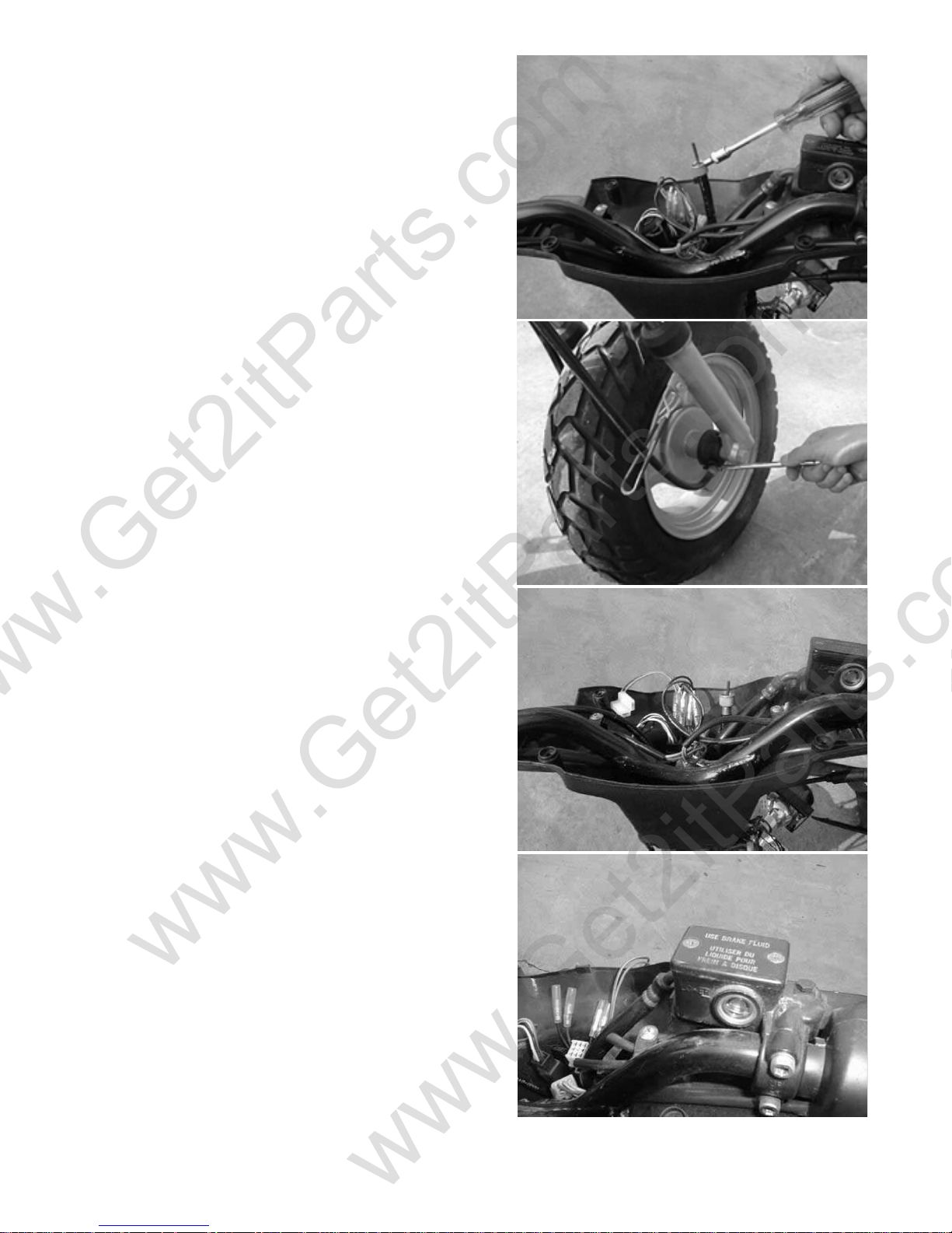
8.3 SPEEDOMETER CABLE REMOVAL
Remove the handlebar cover.
Unscrew speedometer cable nut.
Unscrew the speedometer cable fixing bolt at the front
wheel. Pull out the worn speedometer cable.
Install a new speedometer cable.
NOTE: Before assembling the new speedometer cable,
apply grease on the inner line of this cable.
8.4 HANDLEBAR REPLACEMENT
Remove the rear view mirrors.
Disassemble the upper cover of handlebar.
Disconnect the speedometer cable and connectors of
switches.
Disassemble the rear brake cable and rear brake lamp
connector near the left handlebar.
Remove the right grip assembly.
Disconnect the throttle cable.
Unscrew the brake master cylinder fixing bolt.
Remove the brake master cylinder assembly.
Beamer Rev-2.0.2 Page 36 of 55 11/21/2005
Page 37
www.Get2itParts.com
www.Get2itParts.com
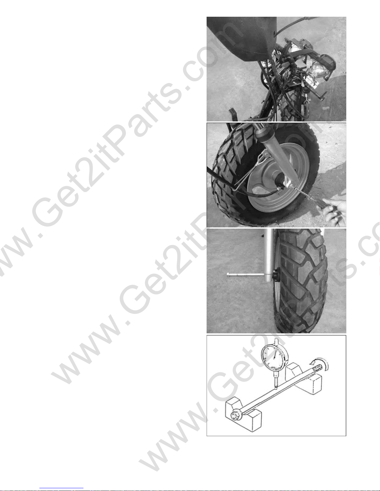
Remove the fixing nut and handlebar bolt on the front
fork. Remove the handlebar.
Torque when installing a handlebar:
M6 nut: 7 - 9 lbf-ft
M10 nut: 22 - 29 lbf-ft
8.5 FRONT WHEEL
Remove the locking nut at the right side of the front
wheel.
Pull out the front wheel axle. Take off the collar.
Remove the speedometer gear unit.
Remove the front wheel assembly.
Torque when replacing the front wheel:
M10 nut: 22 - 29 lbf-ft
NOTE: Apply the grease on the speedometer gear unit
before assembly.
INSPECT THE FRONT WHEELAXLE
Check the wheel axle for bending.
Standard maximum: 0.2 mm
Beamer Rev-2.0.2 Page 37 of 55 11/21/2005
Page 38
www.Get2itParts.com
www.Get2itParts.com
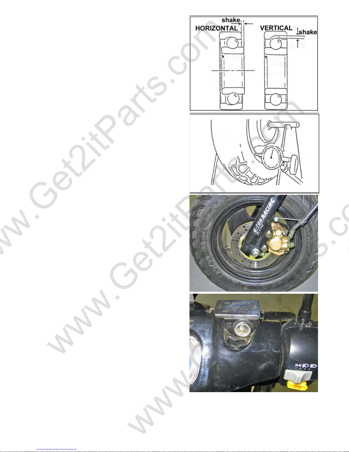
FRONT WHEEL AXLE BEARING INSPECTION
Spin the wheel. Replace with a new bearing if needed.
INSPECT THE FRONT RIM
Check the rim swing limit.
Limit: Replace if the swing is over 2.0mm
8.6 FRONT BRAKE
REPLACING THE FRONT DISK BRAKE
CALIPER
ASSEMBLY
Unscrew the two front disk brake caliper fixing bolts.
Take off the front disk brake caliper.
Torque value when replacing: M8 nut: 14 - 22 lbf-ft
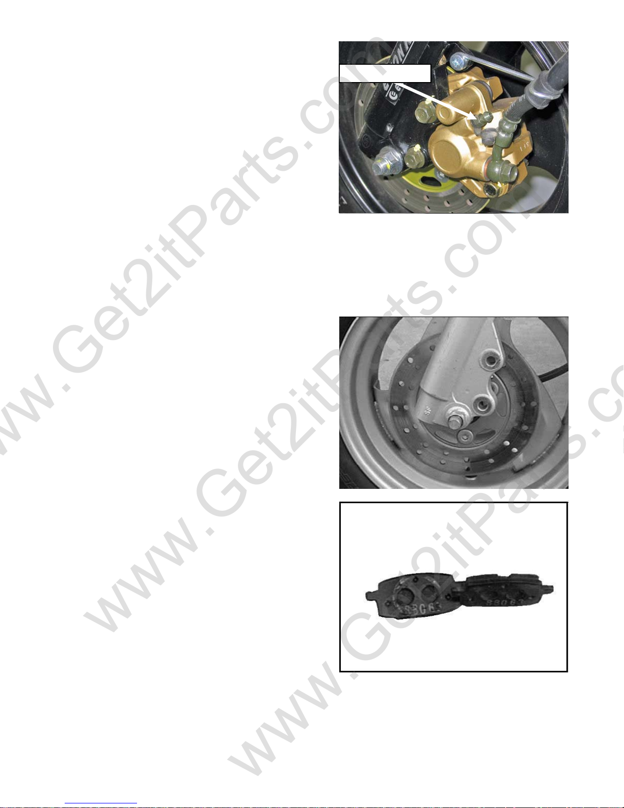
REMOVING THE AIR FROM THE FRONT DISK
BRAKE CALIPER
Fill the brake reservoir with the recommended DOT3
brake fluid in the brake master cylinder at the right
handlebar (see picture).
Be careful not to spill any brake fluid when refilling.
Release and lock the bleeder valve at the disk brake
caliper.
Beamer Rev-2.0.2 Page 38 of 55 11/21/2005
Page 39
www.Get2itParts.com
www.Get2itParts.com
Engage the front brake a few times by pulling the brake
lever gently. Then, hold the front brake level all the
way in; while holding in, release the bleeder valve on
the front caliper to force the air out. Then, lock the
valve. Repeat this action until no more air flows out.
Torque value: 4 lbf-ft
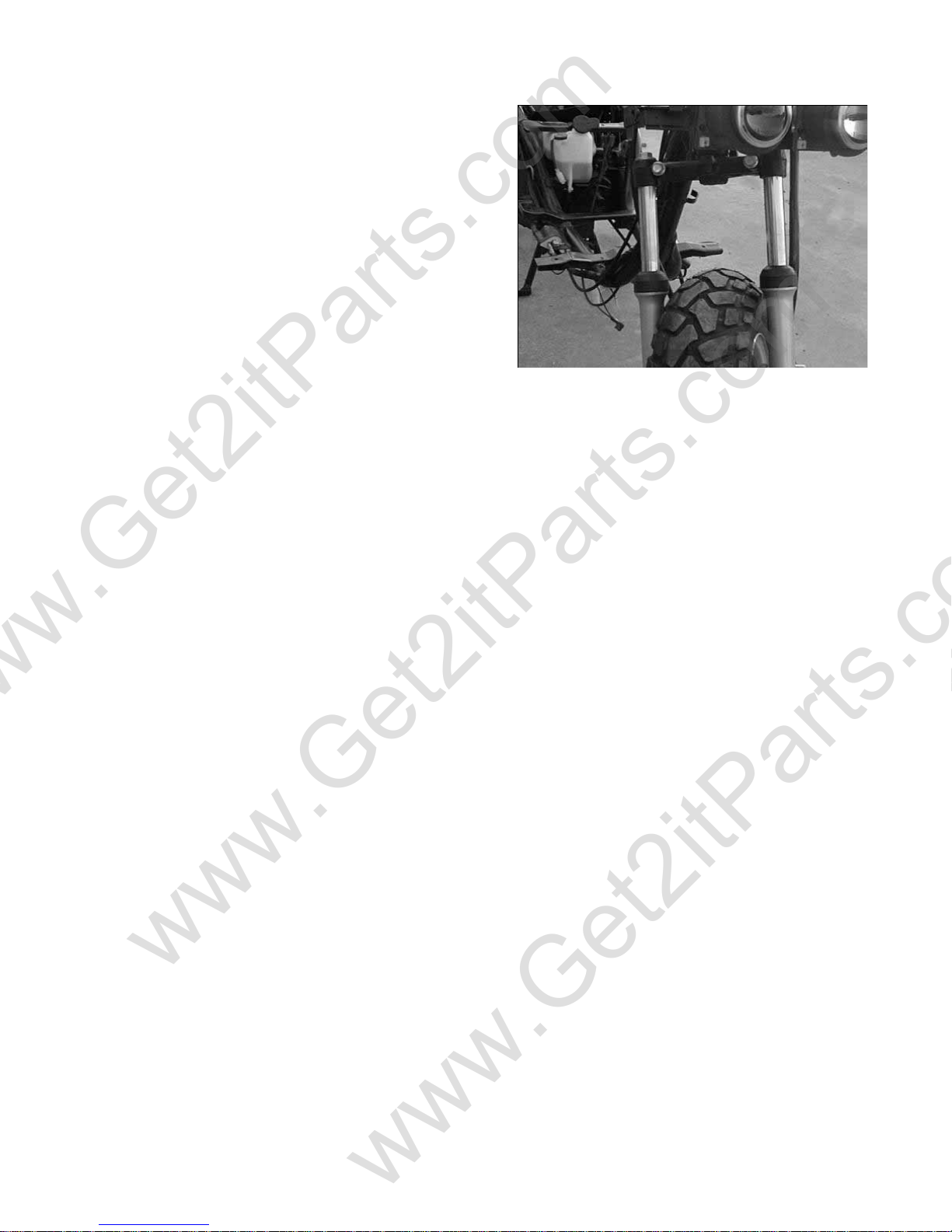
DISASSEMBLING THE FRONT BRAKE DISK
Disassemble the front wheel.
Unscrew the three brake disk fixing bolts.
Remove the brake disk.
Torque of these M8 nuts: 14 – 22 lbf-ft
INSPECT BRAKE DISK
Measure the thickness of the brake disk.
Standard thickness: 3.6 mm
Limit: 3.1 mm
BRAKE SHOES (LINING) INSPECTION
Measure the thickness of the brake lining.
Standard thickness: 4.0 mm
Limit: 3.0 mm
NOTE: Do not get grease on the lining surface.
Bleeder Valve
Beamer Rev-2.0.2 Page 39 of 55 11/21/2005
Page 40
www.Get2itParts.com
www.Get2itParts.com
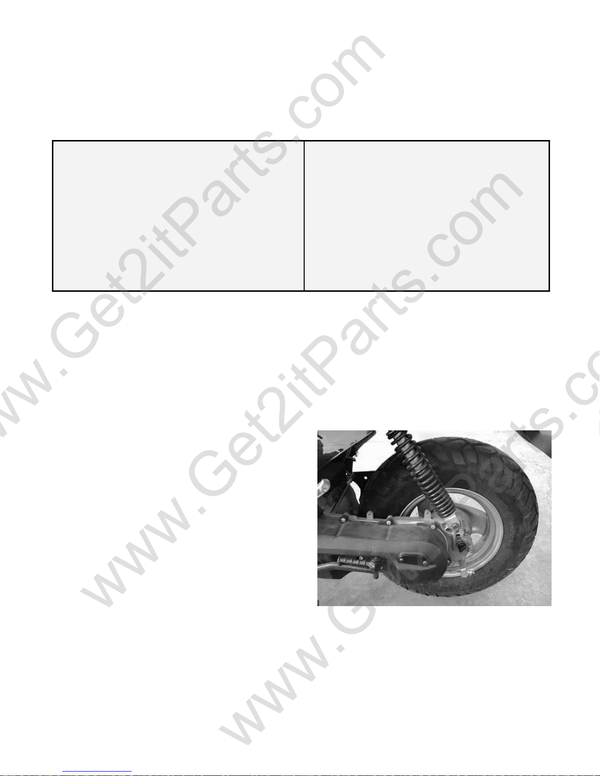
8.7 FRONT FORK
FRONT FORK INSPECTION
Replace if there is any bending or distortion.
FRONT SHOCK ABSORBER INSPECTION
Look for leaks, torn seals, scratched shafts, and
loose connections.
Beamer Rev-2.0.2 Page 40 of 55 11/21/2005
Page 41
www.Get2itParts.com
www.Get2itParts.com
9. REAR WHEELAND BRAKE SYSTEM
9.1 TROUBLESHOOTING
BAD BRAKE PERFORMANCE
¾ WORN BRAKE SHOES
¾ BRAKE ADJUSTED IMPROPERLY
¾ BRAKE LININGS OILY, GREASY, OR DIRTY
¾ WORN BRAKE DRUM
¾ BRAKE ARM SETTING IMPROPERLY ENGAGED
VIBRATION OR WOBBLE
9.2 MAINTENANCE DATA
Brake drum inner diameter
Standard: 110 mm
Limit: 110.5 mm
Lining thickness
Standard (minimum): 4.0 mm
Limit: 2.0 mm
9.3 REAR WHEEL REMOVAL
Remove the muffler.
Unscrew the rear wheel axle nut.
Remove the rear wheel.
Torque value for installation:
M6 nut: 5 – 8 lbf-ft
M14 nut: 40 lbf-ft
¾ BENT RIM
¾ DAMAGED TIRED
¾ WHEEL AXLE IMPROPERL Y TIGHTENED
Beamer Rev-2.0.2 Page 41 of 55 11/21/2005
Page 42
www.Get2itParts.com
www.Get2itParts.com
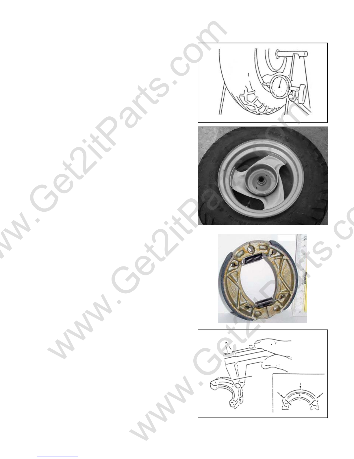
9.4 REAR WHEEL INSPECTION
Measure the rear wheel rim for distortion.
Replace rim if the distortion is over 2.0 mm in difference.
9.5 REAR BRAKE
REAR BRAKE DRUM INSPECTION
Measure the rear brake drum inner diameter.
Replace if the diameter is over 110.5mm.
BRAKE LINING INSPECTION
Measure the brake lining thickness.
Replace if it is less than 2.0 mm.
Beamer Rev-2.0.2 Page 42 of 55 11/21/2005
Page 43
www.Get2itParts.com
www.Get2itParts.com
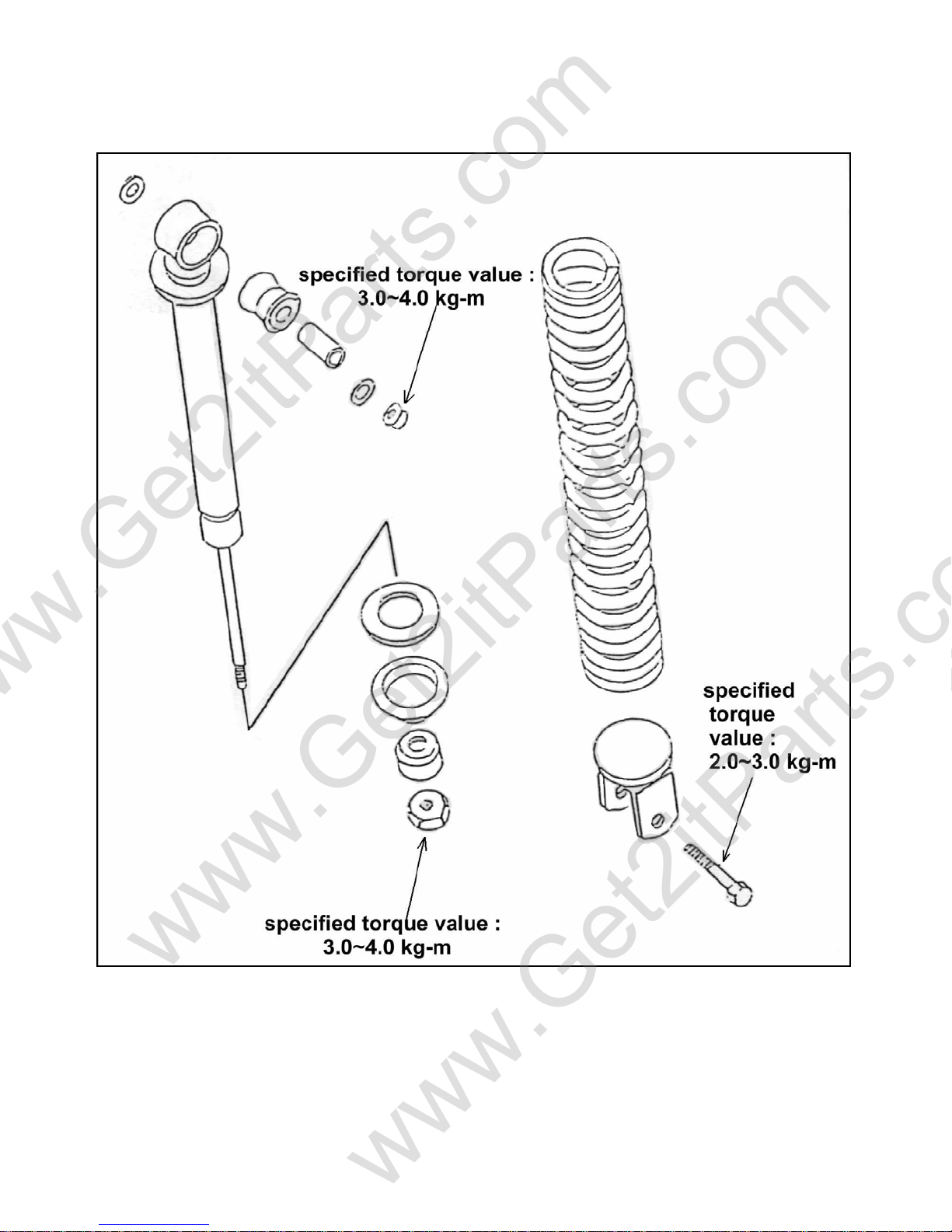
9.6 REAR SHOCK ABSORBER PARTS DRAWING
Beamer Rev-2.0.2 Page 43 of 55 11/21/2005
Page 44
www.Get2itParts.com
www.Get2itParts.com
10. PLASTIC BODY PARTS
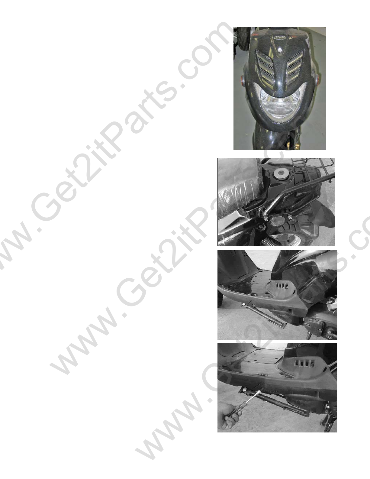
10.1 FRONT FENDER
Unscrew the five fixing screws between the front fender
and leg shield.
Remove the front fender.
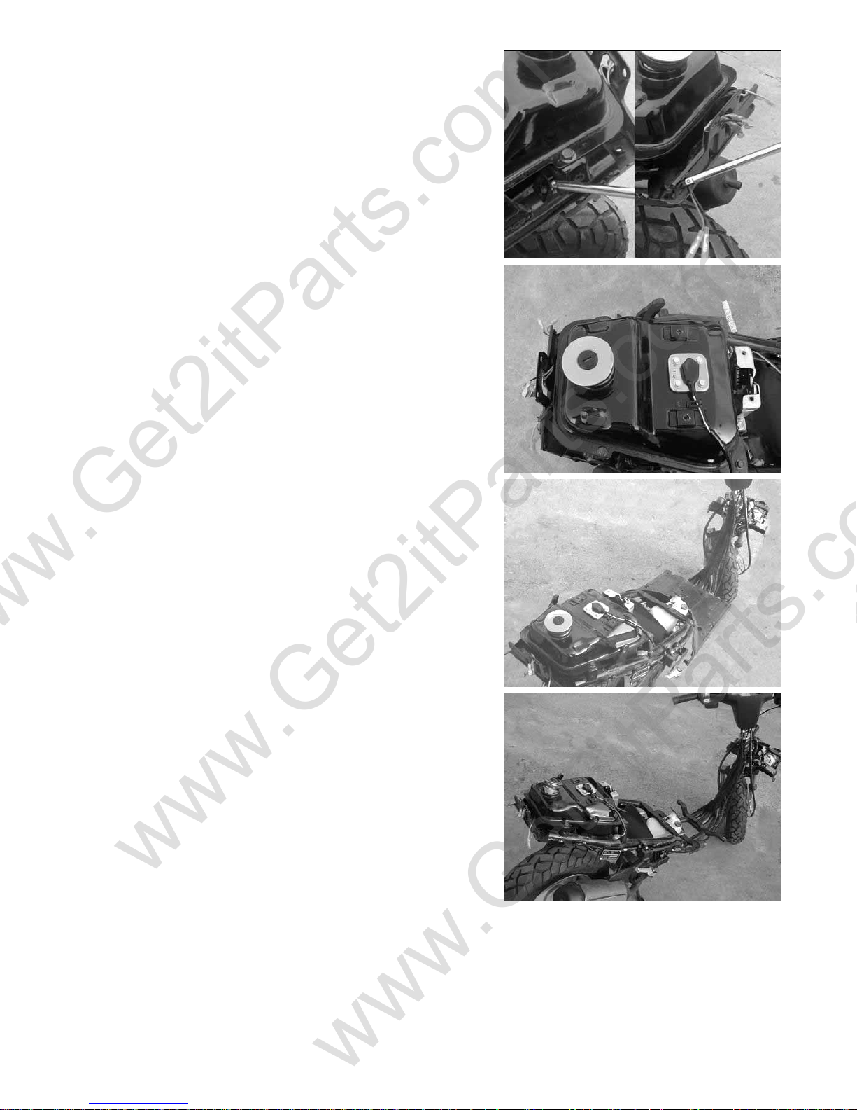
10.2 BODY COVER
Unscrew the four fixing bolts on the rear handle bar.
Remove the rear handle bar.
Unscrew the two fixing screws of each side of the
protective covers.
Beamer Rev-2.0.2 Page 44 of 55 11/21/2005
Page 45
www.Get2itParts.com
www.Get2itParts.com
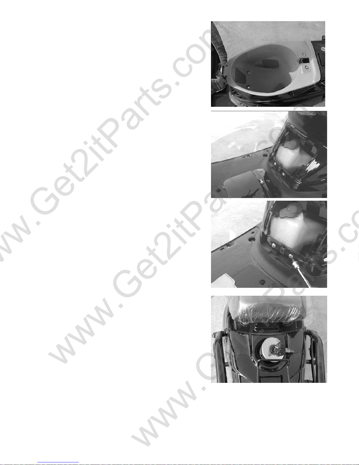
Open the seat.
Unscrew four fixing bolts of the helmet box.
Remove the helmet box.
Unscrew the fixing screws between the body cover and
middle cover.
Remove the middle cover.
Unscrew the two fixing screws of the body cover under
the middle cover.
Open and remove the fuel tank cap.
Unscrew the two fixing screws of the body cover near
the fuel tank cap.
Beamer Rev-2.0.2 Page 45 of 55 11/21/2005
Page 46
www.Get2itParts.com
www.Get2itParts.com
Unscrew two taper screws of the body cover near
the footrest board. Remove the body cover.
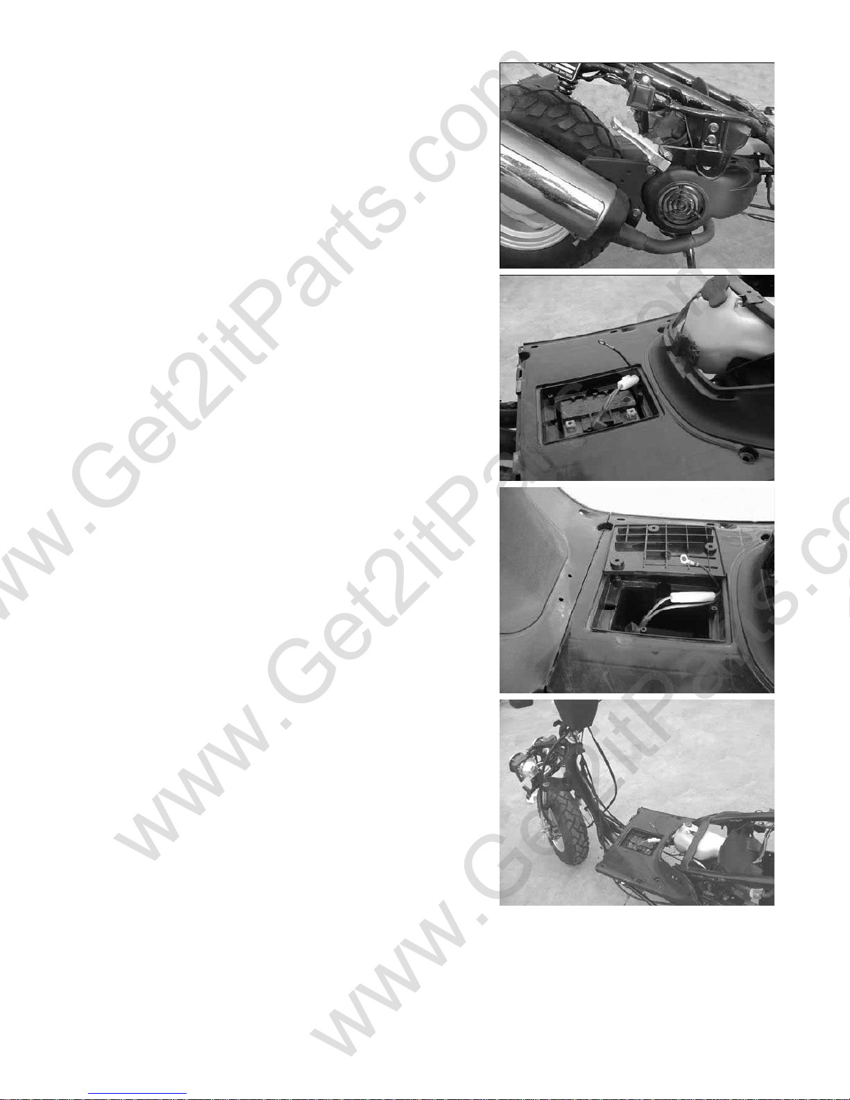
Unscrew three fixing screws of the battery cover at
footrest board.
Remove the battery cover.
Disconnect the negative terminal of the battery, then
disconnect the positive terminal. Remove battery.
Unscrew the fixing screws of the lower cover.
Remove the lower cover.
Unscrew three screws of the leg shield.
Remove the leg shield.
Beamer Rev-2.0.2 Page 46 of 55 11/21/2005
Page 47
www.Get2itParts.com
www.Get2itParts.com
Unscrew four fixing screws near the rear
lamp cover.
Remove rear lamp cover.
Unscrew two fixing bolts of the footrest board.
Remove footrest board.
Torque value:
M6: 5 – 8 lbf-ft
M5: 3 – 4 lbf-ft
Beamer Rev-2.0.2 Page 47 of 55 11/21/2005
Page 48
www.Get2itParts.com
www.Get2itParts.com
11. ELECTRICAL SYSTEM
11.1 TROUBLESHOOTING
ENGINE STARTS BUT STOPS
• IMPROPER IGNITION TIMING
• FAULTY SPARK PLUG
NO SPARK AT PLUG
• ENGINE STOP SWITCH AT “ OFF “
• FAULTY IGNITION COIL
• FAULTY GENERATOR
• FAULTY CDI UNIT
• POOLY CONNECTED:
o Between CDI and ignition coil
o Between alternator and CDI unit
o Between CDI and engine stop switch
o Between ignition coil and spark plug
o Between generator and CDI unit
ENGINE STARTS BUT RUNS POORLY
• IGNITION PRIMARY CIRCUIT
o Faulty generator
o Faulty CDI unit
o Faulty alternator exciter coil
o Loosen contacted terminals
o Faulty ignition coil
• IGNITION SECONDARY CIRCUIT
o Faulty plug
o Loosen contacted spark plug wire
• IMPROPER IGNITION TIMING
o Faulty generator
o Faulty CDI unit
CHARGING SYSTEM FAILURE
• LOOSE, BROKEN OR SHORTED WIRE
• FAULTY ALTERNATOR
• FAULTY IGNITION SWITCH
• LOOSE BATTERY CONNECTION
ENGINE INTERMITTENT POWER
• LOOSE CHARGING SYSTEM CONNECTION
STARTER MOTOR WILL NOT TURN
• DEAD BATTERY
• FAULTY IGNITION SWITCH
• LOOSE OR DISCONNECTED WIRE
STARTER MOTOR AND ENGINE TURN,
BUT ENGINE DOES NOT START
• FAULTY IGNITION SYSTEM
• ENGINE PROBLEMS
• FAULTY ENGINE STOP SWITCH
Beamer Rev-2.0.2 Page 48 of 55 11/21/2005
Page 49
www.Get2itParts.com
www.Get2itParts.com
11.2 IGNITION COIL
Remove the spark plug cap from the spark plug.
Disconnect the ignition coil primary wire.
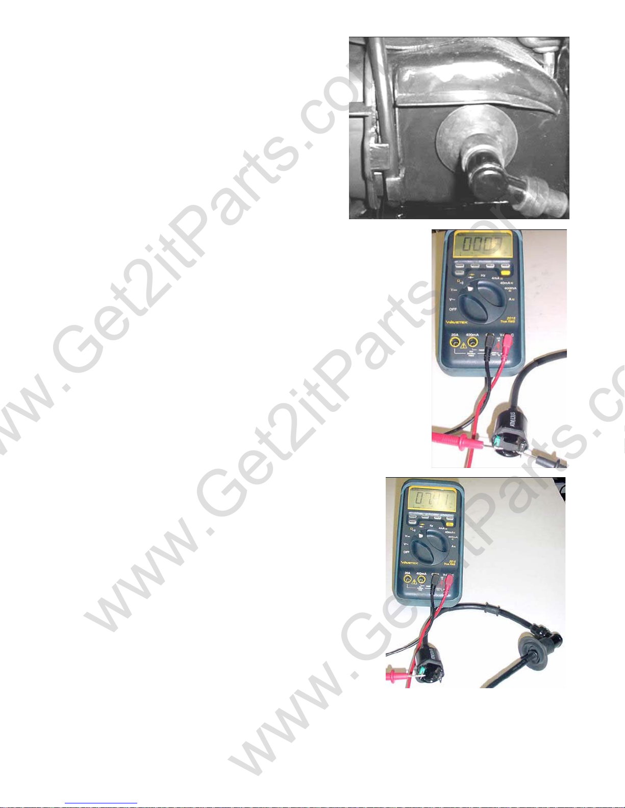
Testing the ignition coil:
• Remove the coil wire cap from the spark
plug
• Unplug the ignition coil primary leads
• Test the primary coil as shown in the
picture. Primary coil resistance should
range between 0.1-0.3 Ω.
• Test the secondary coil as shown in this
picture. Secondary coil resistance
should range between 7.4-12.0 kΩ.
• If the test results fall outside the stated
ranges, replace the ignition coil
assembly.
11.3 IGNITION TIMING
The preprogrammed ignition advance is 15°±
3°/4000rpm.
Ignition timing is controlled by the CDI (Capacitive
Discharge Ignition) module and is set at the
factory via a RCP (ROM Chip Program). The timing
cannot be manually adjusted.
Beamer Rev-2.0.2 Page 49 of 55 11/21/2005
Page 50
www.Get2itParts.com
www.Get2itParts.com
11.4 BATTERY INSPECTION AND MAINTENANCE
CAUTION: The battery emits flammable and explosive fumes during normal operation. Keep away
from sparks, open flame, and other possible sources of ignition. Always provide adequate ventilation
during charging and maintenance of the battery. The battery contains sulfuric acid (an electrolyte).
Contact with skin or eyes may cause severe burns or blindness. Always wear protective clothing and eye
protection when servicing the battery. The electrolyte is toxic. If swallowed, drink large quantities of
water or milk and seek medical attention immediately, or contact a poison control center.
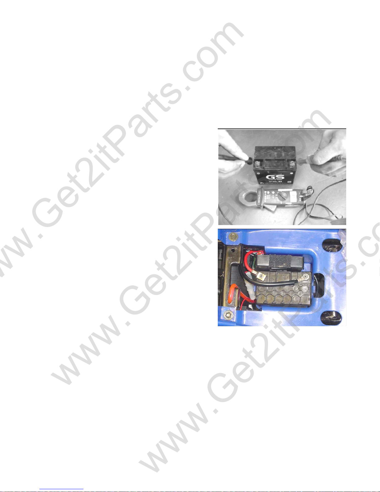
The battery is located under the seat in the battery compartment.
Battery removal:
• Remove the battery retainer strap
• Disconnect the negative (BLACK) battery lead
first
• Disconnect the positive (RED) battery lead
next
• Use caution when disconnecting lead so as
not to cause a spark
• Remove the battery from the battery
compartment
Testing the battery:
• Measure the battery voltage using a multi-meter
set to Voltage
• A fully charged battery should read 13.0-13.5V. An
under charged or faulty battery will be below
12.0V.
• If the battery is showing under charge condition,
charge the battery using a trickle charger at 7
amps for 10 hours. When charging the battery, it
should be removed from the unit. Connect the
charger lead to the battery before turning on the
charging unit. Turn the charging unit off before
disconnecting the charging leads from the battery.
Retest the battery voltage. If the battery voltage
shows an under charge condition after charging,
replace the battery.
Beamer Rev-2.0.2 Page 50 of 55 11/21/2005
Page 51
www.Get2itParts.com
www.Get2itParts.com
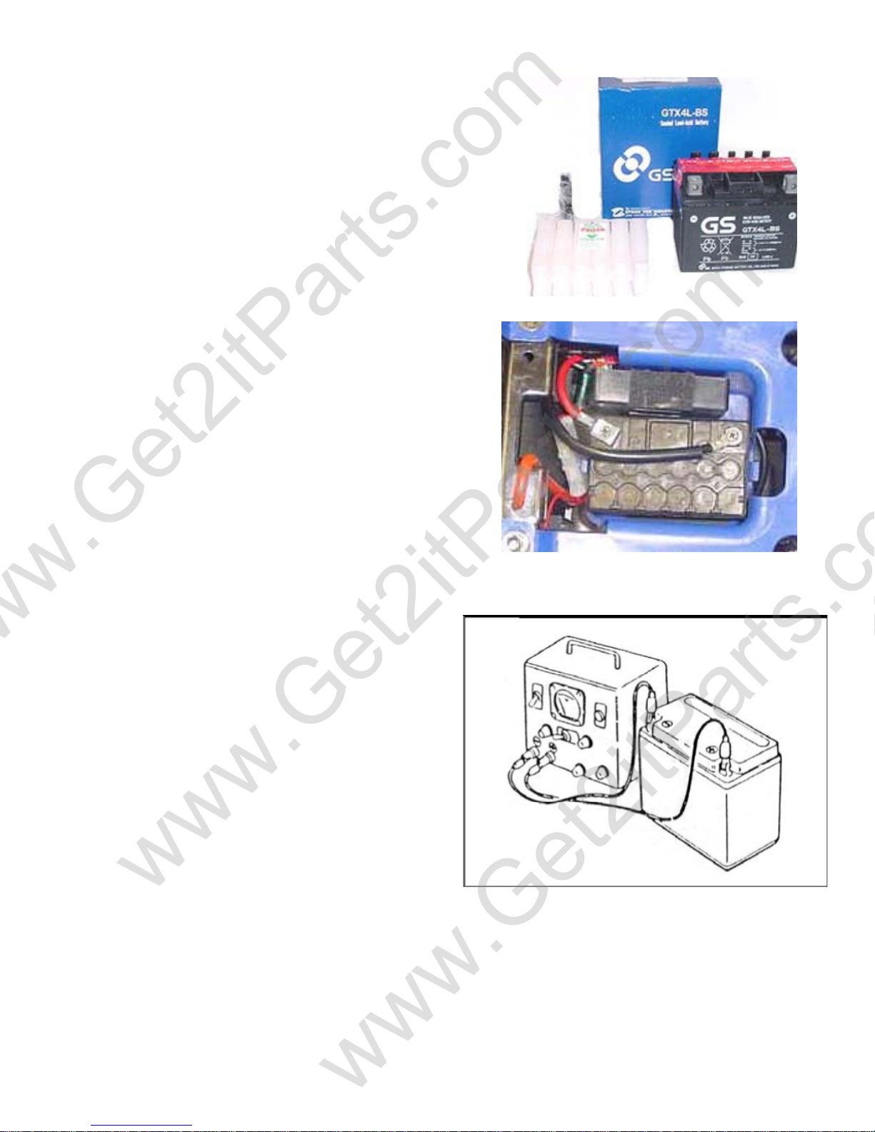
New battery preparation:
• The new battery is shipped dry with the electrolyte in a
separate container. Remove the battery cell caps and install the
electrolyte in the battery cells. CAUTION: Electrolyte contains
sulfuric acid that can cause severe burns if contact is made
with the skin or eyes. • Allow the battery to completely absorb
the electrolyte (approximately one (1) hour). The battery
should have a full charge. The battery is a gel acid battery and
will not show any liquid electrolyte when fully absorbed.
DO NOT place the new battery on a charger as this can
damage the cell plates and make the battery unusable.
Battery installation:
• Place the battery in the battery compartment.
• Clean the battery terminals and lead connectors of all dirt
and corrosion.
• Attach the positive (RED) lead to the [+] positive
terminal of the battery first.
• Attack the negative (BLACK) lead to the [-] negative
terminal of the battery next.
• Check the lead routing to ensure they are clear of
obstruction and do not fall between the battery and unit
body where they could be abraded or otherwise damaged.
• Attach the battery retainer strap to secure the battery in
place.
Battery charging:
• If the battery become discharged or shows low
voltage you can recharge the battery using a 12 volt
battery trickle charger.
• Connect the positive lead of the charger to the
positive terminal of the battery.
• Connect the negative lead of the charger to the
negative terminal of the battery.
• Turn on the charger and allow the battery to charge
from 4 to 6 hours.
• Test the battery voltage after charging it should give
a reading of between 12-and 13 volts.
• If after charging the battery is still indication a low
voltage or the battery will not hold the charge for
more than a day or two the battery should be
replaced.
ETON recommends replacing the battery every two years for optimal performance.
Beamer Rev-2.0.2 Page 51 of 55 11/21/2005
Page 52
www.Get2itParts.com
www.Get2itParts.com
Battery Storage:
If the vehicle will not be in use for an extended period of time, the battery should be removed and stored
in a location that will ensure that battery will not freeze.
DO NOT store the battery on a concrete surface as it can draw the charge from the battery and
damage the battery plates.
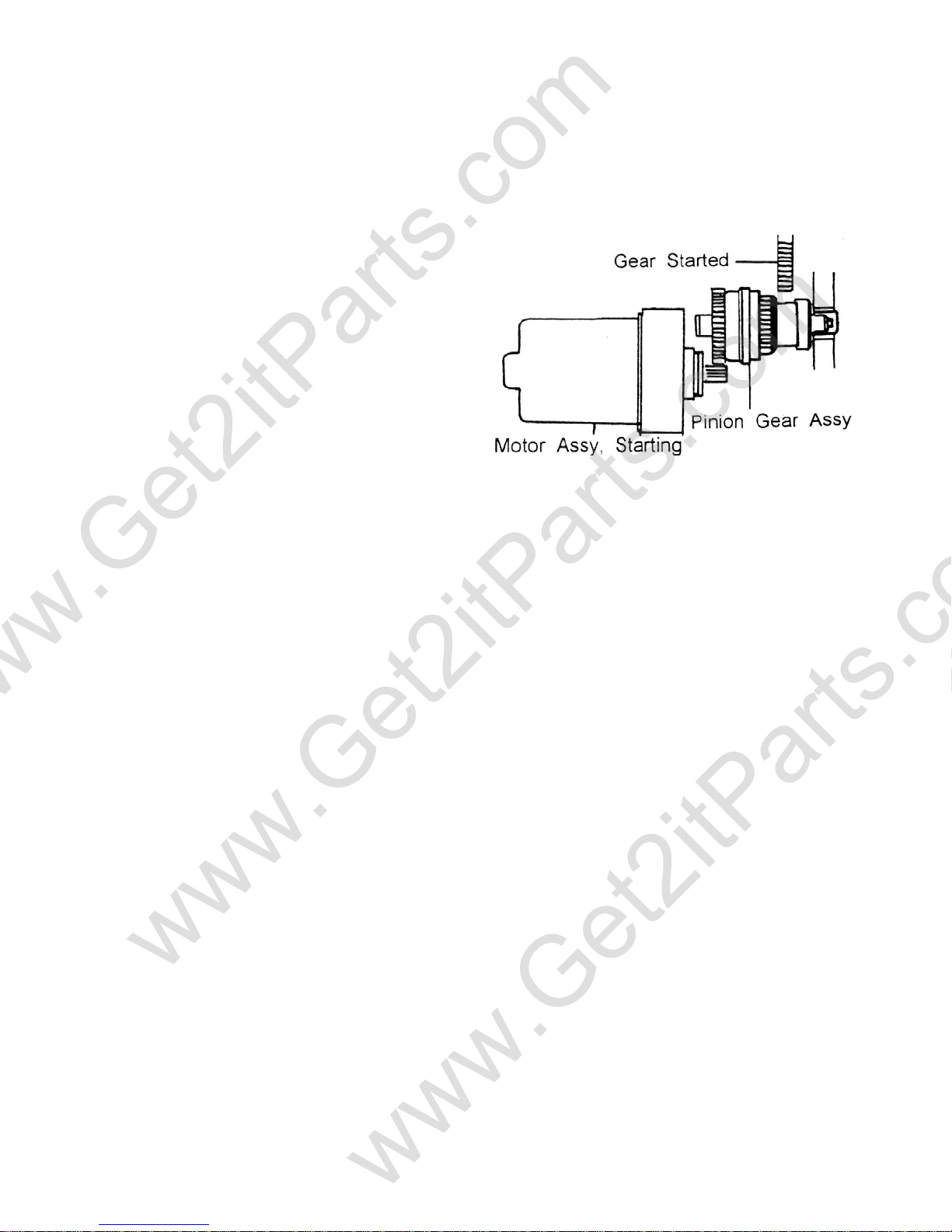
11.5 STARTER MOTOR
The starter motor is attached to the engine.
Unscrew the two starter motor fixing
Bolts and remove the starter motor.
Disconnect the motor wire.
Connect motor and battery to check
the functionality of the motor.
(See chapter #7)
Beamer Rev-2.0.2 Page 52 of 55 11/21/2005
Page 53
www.Get2itParts.com
www.Get2itParts.com
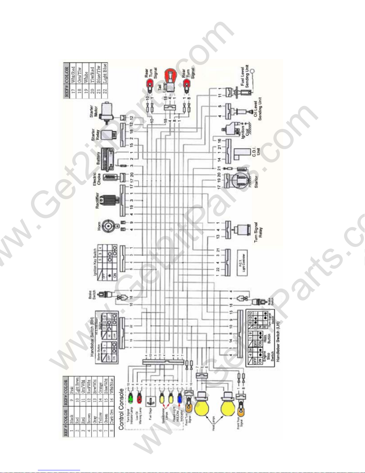
11.6 WIRING DIAGRAMS
Beamer PN2
Beamer Rev-2.0.2 Page 53 of 55 11/21/2005
Page 54
www.Get2itParts.com
www.Get2itParts.com
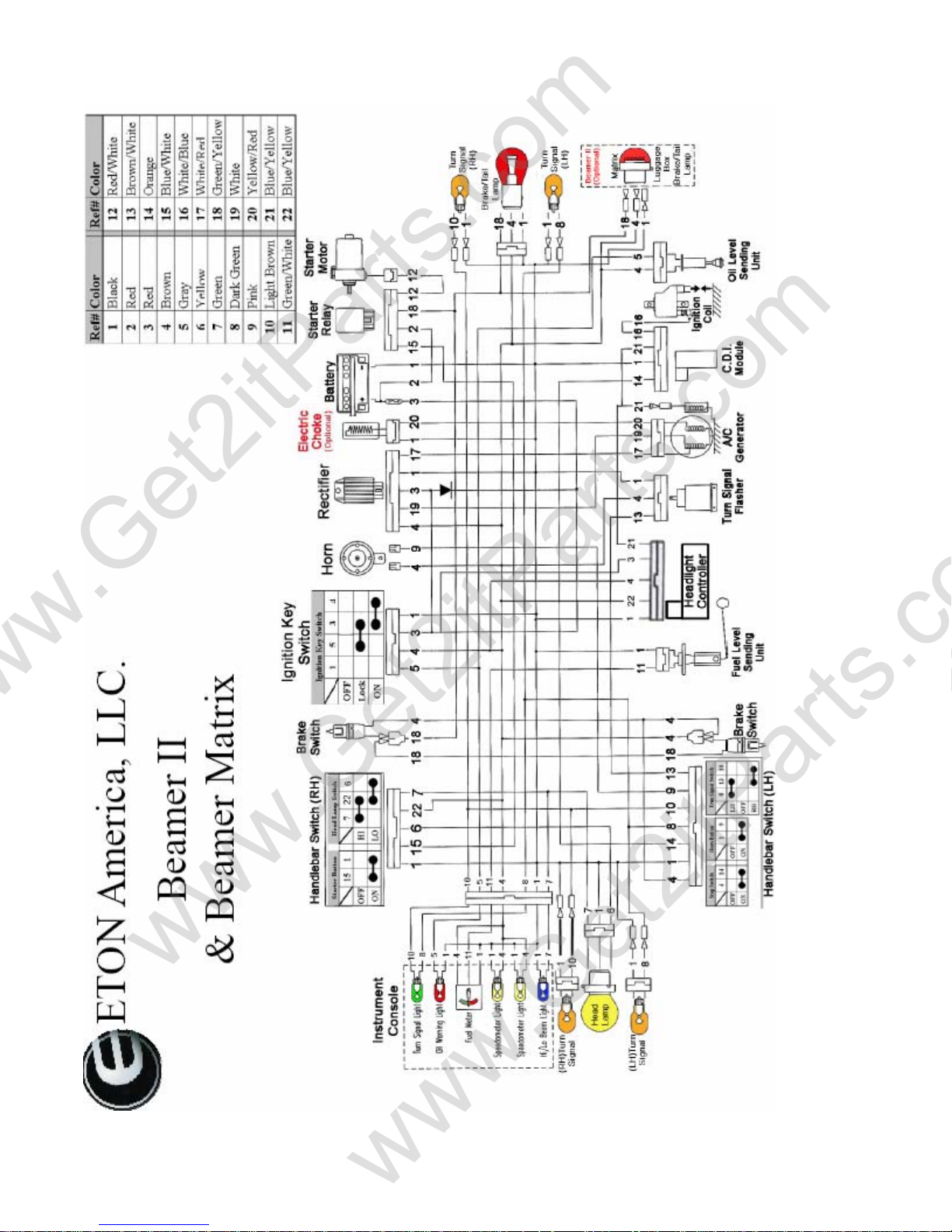
Beamer II
PN2B
&
Beamer
Matrix
PN2C
Beamer Rev-2.0.2 Page 54 of 55 11/21/2005
Page 55
ETON America, LLC
www.Get2itParts.com
www.Get2itParts.com
Bulletin No:
Date:
Service Bulletin
0007
08/22/2000
Beamer Brake Lights Stay on
BEAMER
Units Affected :
Beamer Scooters
Reason for bulletin:
Brake lights stay on after brake released.
Cause:
Light on will also draw on battery.
Repair:
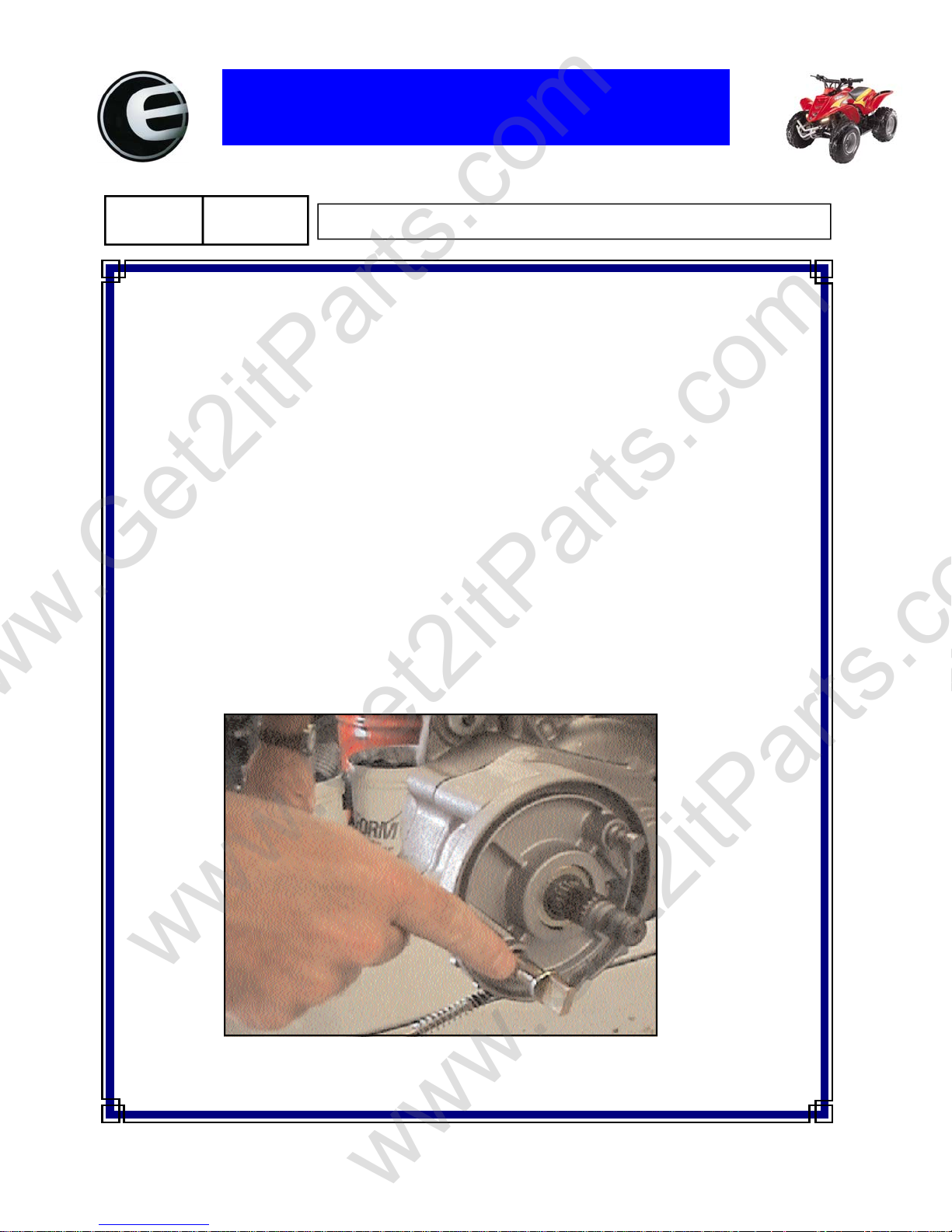
Lube rear brake cam-it will bind in housing and cause brake lights to stay on. Verify Repair: Retest brake lights for proper operation.
REAR BRAKE CAM LUBE
Step 1 : Remove rear wheel.
Step 2 : Remove rear brake shoes.
Step 3 : Remove rear brake cam arm and cable.
Step 4 : Remove rear brake cam and lube shaft and lube shaft housing.
Note: see illustrations below.
Flat Rate Code: 007
Flat Rate: 0.4 Hours
Page 56
ETON America, LLC
www.Get2itParts.com
www.Get2itParts.com
Service Bulletin
Bulletin No:
Date:
1. PAPER FUEL FILTERS -CAUSE: RESTRICTIVE FUEL FLOW
THEY CLOG EASIER
THEY WILL SHOW FUEL IN FILTER, BUT THERE WILL BE NO FUEL IN
CARBURATER BOWL.
REPAIR: REPLACE WITH AN E-Z FLO WITH FILTER OR A STONE TYPE FILTER.
2. EXHAUST RESTRICTERS-CAUSE: LACK OF POWER
LOSS OF POWER
FOULED PLUGS
REPAIR: CLEAN RESTRICTER ONCE A MONTH OR REMOVE RESTRICTER AND USE
THROTTLE STOP SCREW.
3. AIR FILTERS ---------------CAUSE: LACK / LOSS OF POWER
LEAN CONDITIONS
POOR THROTTLE RESPONSE
REPAIR: CLEAN AFTER EVERY 3-5 RIDES, MORE FREQUENTLY IN DUSTY CONDITIONS.
USE A GOOD QUALITY FOAM FILTER SPRAY.(BEL-RAY FOAM FILTER SPRAY)
4. BATTERIES----THE BATTERIES FOR ALL ETON VEHICLES ARE MAINTANCE-FREE .
PROPER SERVICE PROCEDURES ARE AS FOLLOWS:
1. FILL BATTERY WITH BATTERY PACK SUPPLIED.
2. REMOVE FUNNEL AND LET BATTERY STAND WITH CAP OFF FOR AT LEAST 1 HR.
3. ALL FLUID IN BATTERY SHOULD ABSORBED BY BATTERY PLATES BEFORE CAP
4. BATTERY IS READY TO BE CAPPED WHEN ALL ELECTROLYTE IS ABSORBED.
5. MEASURE BATTERY VOLTAGE ACROSS TERMINALS AND IT SHOULD BE ABOVE
6. NEVER ADD WATER OR HYDRO-SULFURIC ACID TO BATTERY HYDRO-SULFURIC
7. IF CHARGING IS REQUIRED SLOW CHARGE @ 5 AMPS FOR 5 HRSAND FAST
0008
08/25/2000
IS INSTALLED.
(YOU SHOULD BE ABLE TO TURN BATTERY UPSIDE DOWN AND NO FLUID COME
OUT)
12.8 VOLTS IF PLATES HAVE ABSORB ED ALL EL ECTROLYTE.
ACID WILL CAUSE A SERIOUS CHEMICAL REACTION AND COULD CAUSE HARM
TO YOU AND WILL DAMAGE BATTERY. ADD ING WA TER WILL ALSO DAMAGE
BATTERY.
CHARGE @ 5 AMPS FOR 30 MIN.
Technical T ips
Page 57
ETON America, LLC
www.Get2itParts.com
www.Get2itParts.com
Service Bulletin
Bulletin No: 0033
Date: 04/01/2004
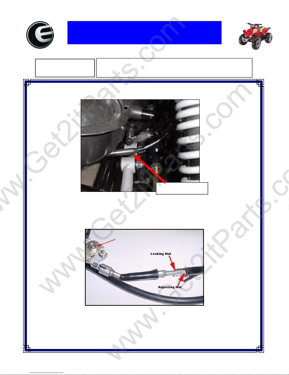
To adjust the oil pump flow on a two cycle oil injected engine you must adjust the oil pump cable length. . The
Oil pump cable is located on the right hand side of the engine just above the (RH) A-arm
Oil Pump Flow Adjustment
all Oil Injected two cycle Engines
Oil Pump Cable Location
To reduce the oil flow you must lengthen the cable by loosening the lock nut and turning the adjusting nut
counter clockwise then retighten the locking nut. To increase the oil flow you would shorten the cable by
turning the adjusting nut clockwise.
Oil Pump
Page 58
ETON America, LLC
www.Get2itParts.com
www.Get2itParts.com
Service Bulletin
Bulletin No.:
Date: 05/01/2006
SB-0040
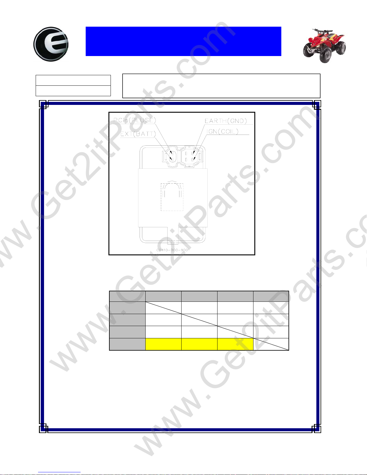
C.D.I. Module Specifications
Beamer II (PN2B) & Beamer Matrix (PN2C)
PN2B & PN2C -- C0410-B00-9001
Electric resistance(Ω) specification
-
EXT
IGN
Pcin
GND 11-14K 1-3K 40-50K
EXT IGN Pcin GND
10-12K 60-80K ∞
7-8K
28-32K 10-12K
28-32K ∞
∞
Specifications highlighted in yellow are the suggested critical testing points. Test points should be
tested first.
We suggest using analogy type multi-meter to test the electric resistance. We have found using
digital type meter produces to many inaccurate readings.
Page 59

ETON America, LLC
www.Get2itParts.com
www.Get2itParts.com
Service Bulletin
Bulletin No.:
Date: 07/26/06
FIG #1
FIG #3
SB-0046
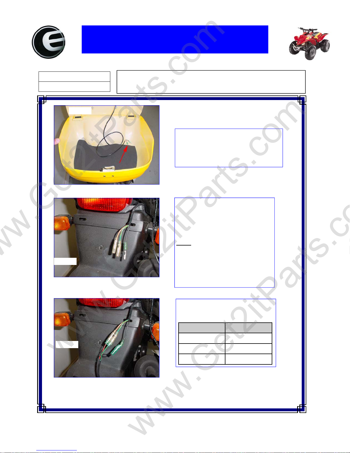
Beamer Luggage box installation
1st check the contents of package
1-Luggage box
1-Set of keys
1-Mounting plate
1-Luggage box pad
4-Mounting brackets
4-Bolts
4-Washers
4-Nuts
FIG #2
The mounting plate is positioned on the bottom
of the luggage box with the smooth side toward
the box. The (4) bolts and washers are pushed
through the box and plate from inside the box
using the holes indicated in Fig #3.
Place the box and plate over the rear rack and
attach using the (4) brackets, washers and nuts
supplied. See Fig #4.
FIG #4
Page 60
ETON America, LLC
www.Get2itParts.com
www.Get2itParts.com
Service Bulletin
Bulletin No.:
Date: 07/26/06
FIG #5
FIG #6
SB-0046
Beamer Luggage box installation
Once the luggage box is installed push the
rear brake light LED wires through the hole
in the box as shown in Fig #5 and install the
luggage box pad.
The wires for the LED hookup are located on the rear of the bike around the
rear taillight. They may be tucked in
under the harness on the left hand side of
the unit..
ONLY the Beamer II & III and
Note:
the Matrix & Matrix II have been pre
wired for the luggage box brake light.
If you have the older model Beamer the
LED will have to be hard wired into
the rear taillight.
FIG #7
Connect the wires from the LED light to
the main harness using the following
wiring table.:
Box Wires Main Harness
Red Brown
Green Green
Black Black
Page 61
ETON America, LLC
www.Get2itParts.com
www.Get2itParts.com
Service Bulletin
Bulletin No:
Date:
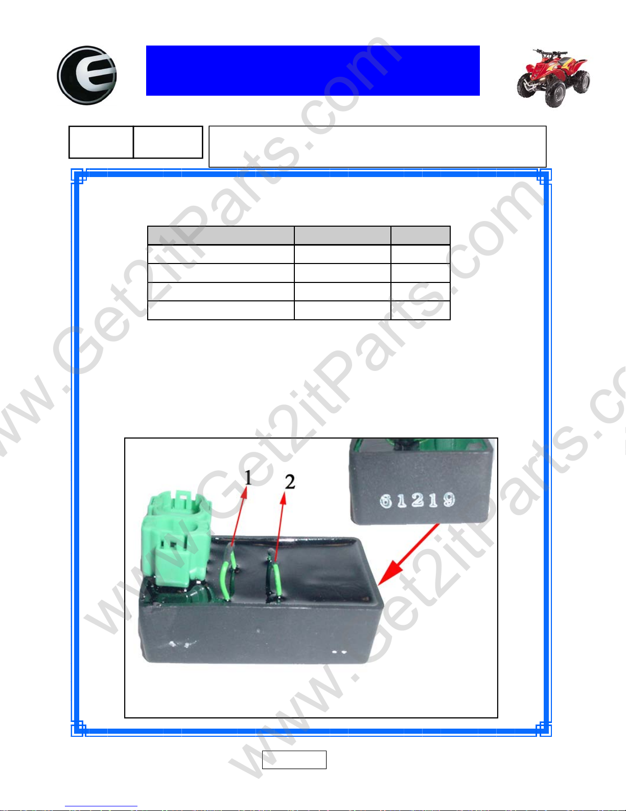
The Beamer III and Matrix II CDI Version 3.5.0.0 has two speed limiter wires located on the back side.
The following chart denotes the speed control of these wires:
0049
02/15/2007
Beamer CDI Version 3.5.0.0 Max Speed BHP
Wire #1 & #2 Uncut (Factory) 25MPH (30KPH) 1.9
Wire #1 Cut & #2 Uncut 30MPH (40KPH) 3.4
Wire #1 & #2 both Cut 40MPH (60KPH) 3.8
Beamer III & Matrix II
Speed Limiter CDI Version 3.5.0.0
Page 1 of 1
Page 62
ETON America, LLC
www.Get2itParts.com
www.Get2itParts.com
Service Bulletin
Bulletin No:
Date:
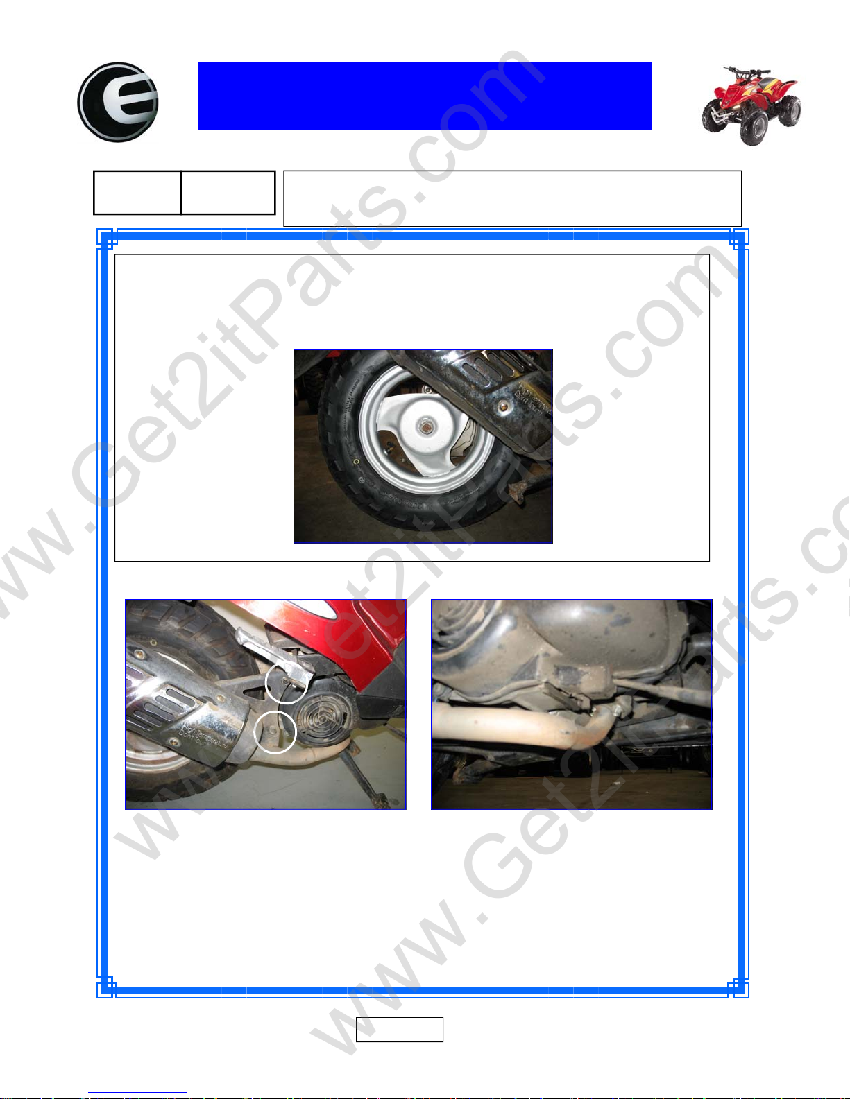
Put the bike on the center stand and let the exhaust cool down before installation . Then remove the (2)
10mm bolts from the exhaust pipe flange on the bottom of the cylinder. The remove the (2) 12mm bolts
from the exhaust RH side. Once the exhaust is removed then, remove the 24mm wheel nut and washer.
Remove the wheel and replace with a new factory wheel and rim.
0050
03/01/2007
Beamer rear wheel inspection and removal.
Page 1
Page 63
Bulletin No:
www.Get2itParts.com
www.Get2itParts.com
Date:
ETON America, LLC
Service Bulletin
0051
03/01/2007
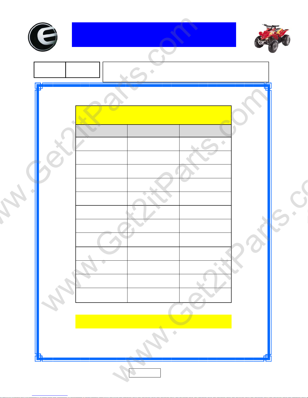
E-TON ATV, Scooter and Utility Kart
Headlight W attages
HeadLightWattages
Model Factory Maximum
Viper70‐4 10w
Viper90‐4 10w
Viper150 20w
Yukon150 20w
Vector250 35w
BeamerII 18w
BeamerIII 18w
BeamerMatrix 18w
BeamerR2 18w
BeamerR4 18w
Rover N/A
12w
12w
50w
50w
90w
24w
24w
24w
24w
50w
12w
RoverGT N/A
Per:JI‐EEEngineers 5/24/2007
24w
Page 1
Page 64
ETON America, LLC
www.Get2itParts.com
www.Get2itParts.com
Service Bulletin
Bulletin No:
Date:
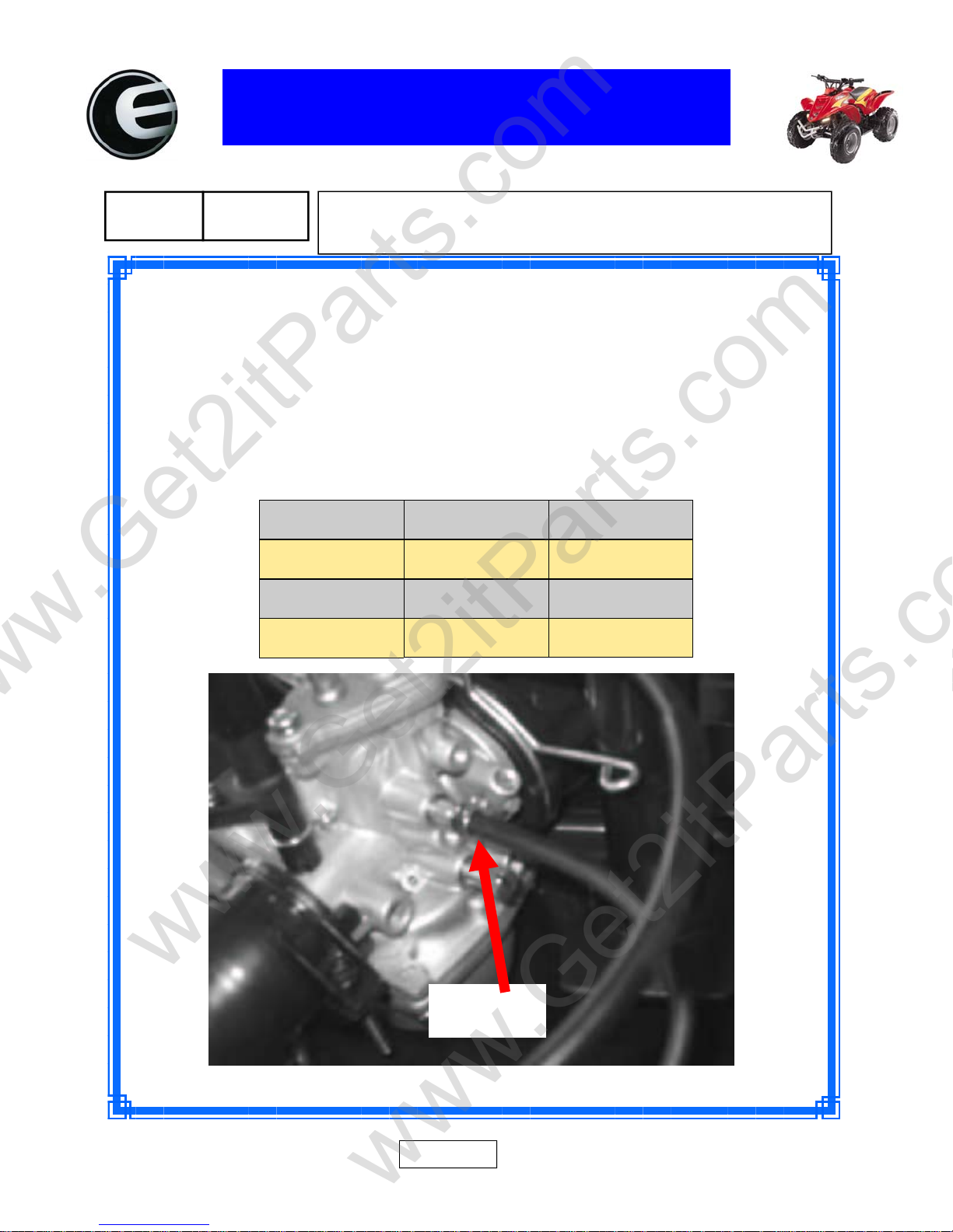
The following steps are used to determine if the 2 cycle oil injector pump is
functioning properly on E-TON 50cc and 90cc 2 cycle engines.
1. Fill the fuel tank with a pre mix fuel / 2 cycle oil mixture at a 50 : 1 ratio.
2. Disconnect the oil pump line at the carburetor.
3. Start the engine and count the drops per minute at the various RPM listed
in the table below
0052
06/12/2007
E-TON 50 & 90cc 2 cycle engine
Oil pump testing
.
RPMs 50cc 90cc
1700 (idle) 3-4 5-6
4000 5-9 12-14
7000 8-12 20-22
Oil Pump
Line
Note: 32 Drop = aporx -1cc
Page 1
Page 65
www.Get2itParts.com
www.Get2itParts.com
Beamer Rev-2.0.2 Page 55 of 55 11/21/2005
 Loading...