

Page 1
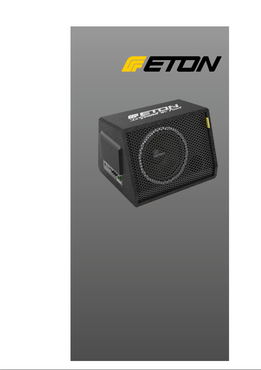
Aktiv Subwoofer Box
Active Subwoofer Box
MOVE
MOVE
10-300AR
10-300AR
12-400AR
12-400AR
EINBAU-ANLEITUNG
INSTRUCTION MANUAL
Page 2

Inhalt
Content
Einführung 1
Sicherheitshinweise 2
Ausstattung 3
Einbau und Verkabelung 6
Bedienung und Einstellung 1 0
Fehlerbehebung 12
Technische Daten 14
Einführung
ETON bedankt sich ausdrücklich für den Kauf
dieses Subwoofers und beglückwünscht Sie
zu der Wahl dieses ausgezeichneten Produktes.
ETON Subwoofer garantieren hervorragende
Leistungen. Die elektrischen, mechanischen
und klanglichen Eigenschaften bleiben über
die gesamte Lebensdauer des Produktes erhalten. Wir wünschen Ihnen viel Freude beim
Hören.
Introduction 1
Safety instructions 2
Features 3
Installation and wiring 6
Operation and adjustments 1 0
Troubleshooting 12
Technical data 14
Introduction
ETON expressly thanks you for deciding to
purchase this subwoofer and congratulates
you on the selection of this excellent product.
The ETON subwoofers are a guarantee for outstanding performance. The electrical, mechanical and tonal characteristics will be maintained
at the original high standard throughout the entire operational life of this product. We wish you
many pleasant listening hours.
Die vorliegende Bedienungsanleitung wurde so
konzipiert, dass Sie Ihnen eine korrekte Installation ermöglicht. Sie enthält Informationen und
grundsätzliche Vorgehensweisen für die korrekte Funktionsweise des Produktes. Bitte lesen
Sie die Bedienungsanleitung sorgfältig, bevor
Sie mit der Installation oder dem Anschluss des
Subwoofers beginnen.
1
The current operational instructions are designed to ensure correct installation of the
loudspeakers. They contain information and
essential procedures for the correct operation of the product. Please carefully study the
operating instructions before beginning with
the installation or the connection of the subwoofer.
Page 3

Sicherheitshinweise Safety instructions
Achtung !
Bitte lesen Sie alle Warnungen in dieser Anleitung. Diese Informationen sind hervorgehoben und eingefügt, um Sie über mögliche persönliche Schäden oder Beschädigungen von
Sachwerten zu informieren.
Hörschäden
DAUERHAFTES AUSGESETZTSEIN VON
LAUTSTÄRKEN ÜBER 85 dB KANN ZUR
SCHÄDIGUNG DES GEHÖRS FÜHREN.
VERSTÄRKER BETRIEBENE AUTOHIFIANLAGEN KÖNNEN LEICHT SCHALLDRÜCKE ÜBER 130 dB ERZEUGEN UND IHR
GEHÖR NACHHALTIG SCHÄDIGEN. BITTE
BENUTZEN SIE DEN GESUNDEN MENSCHENVERSTAND UND VERMEIDEN SIE
SOLCHE RISIKEN.
Lautstärke und Fahrerbewusstsein
Der Gebrauch von Musikanlagen kann
das Hören von wichtigen Verkehrsgeräuschen
behindern und dadurch während der Fahrt
Gefahren auslösen.
ETON übernimmt keine Verantwortung für
Gehörschäden, körperliche Schäden oder
Sachschäden, die aus dem Gebrauch oder
Missbrauch seiner Produkte entstehen.
Attention !
Please read all warnings found in this manual.
This information is highlighted and included to
inform you of the potential danger of personal
injury or damage to property.
Hearing Damage
CONTINOUS EXPOSURE TO SOUND
PRESSURE LEVELS OVER 85 dB MAY
CAUSE PERMANENT HEARING LOSS.
HIGH POWERED AUTO-SOUND SYSTEMS
MAY PRODUCE SOUND PRESSURE LEVELS OVER 130 dB. THIS MAY CAUSE DAMAGE OF HEARING. USE COMMON SENSE AND AVOID SUCH RISKS!
Volume and Driver Awareness
Use of sound components can impair your
ability to hear necessary trafc sounds and
may constitute a hazard while driving your
automobile.
ETON accepts no liability for hearing
loss, bodily injury or property damage
as a result of use or misuse of this
product.
2
Page 4
Ausstattung Features
Nehmen Sie Ihr Fahrzeug nicht in Betrieb, bevor alle Komponenten des
Lautsprechersystems fest und sicher
eingebaut sind. Lose Teile können im
Falle eines plötzlichen Bremsmanövers oder eines Unfalls zu gefährli-
chen, iegenden Geschossen werden.
Bohren oder schrauben Sie nicht in
eine Fahrzeugverkleidung oder einen
teppichbezogenen Boden, bevor Sie
sich versichert haben, dass darunter keine wichtigen Teile oder Kabel
sind. Achten Sie auf Benzin-, Brems-,
Ölleitungen und elektrische Kabel bei
der Planung für die Montage.
Wir empfehlen die Fahrzeugbatterie
abzuklemmen. Bitte erfragen Sie in Ihrer Fachwerkstatt ob ein Trennen der
Batterie ohne Probleme möglich ist.
WICHTIG!
Die ETON MOVE Aktivwoofer sind nur zum
Betrieb in Fahrzeugen mit einer Bordspannung von +12 Volt und negativer Masse
vorgesehen. Achten Sie darauf, das der
Verstärker nicht mit dem Innenraum oder
Teilen des Innenraums in Berührung
kommt, da der Verstärker Hitze abstrahlt.
Sorgen Sie für eine entsprechende Belüftung.
Do not use your automobile until all
components of the loudspeaker system have been secured to the interior
framework. Failure to do so may turn
a component into a dangerous, ying
projectile during a sudden stop or accident.
Do not drill or drive screws through
any vehicle interior or carpeted oor
before inspecting the underside for
potential punctures to control lines or
cables. Be sure to avoid all fuel lines,
brake lines, electrical cables or oil lines
when planning the installation.
We recommend to disconnect the
battery. Please ask your car dealer if
disconnecting the battery is possible
without any problem.
IMPORTANT!
This amplied subwoofer system is designed for operation in vehicles with 12-volt
Negative ground electrical systems only.
Make sure that the amplier does not get in
contact with the compartment due to heat,
which can be radiated from the amplier.
Vorsicht beim Entfernen von Innenverkleidungen. Die Fahrzeughersteller verwenden verschiedenste Befestigungsteile die bei der Demontage
beschädigt werden können.
Caution: Use care when removing interior trim panels. Car manufacturers
use a variety of fastening devices
that can be damaged in the disassembly process.
3
Page 5

Ausstattung Features
Eingebauter 150 / 200 Watt Verstärker.
Beinhaltet einen High power Monobassverstärker mit integrierter Regelung für
Empndlichkeit, Tiefpasslterung und Bass
EQ zur akustischen Anpassung an die
meisten Serien- sowie Nachrüstanlagen
abgestimmt auf den Subwoofer.
Kabelgebundene Pegelfernbedienung.
Diese Fernbedienung funktioniert als Bass
Boost Kontrolle. Sie regelt nicht den Pegel,
sondern den Bass Boost zwischen 0-+18dB
bei 45 Hz. Sie wird mit einem 5 Meter langen
Verbindungskabel geliefert, welches auch
bis zum Armaturenbrett reicht, wenn der
Subwoofer im Kofferraum installiert ist.
Tunnel Port Design:
Großer Bassreexkanal der dazu dient den
rückwärtigen Schallanteil für größtmögliche
Bassausbeute in kleinem Gehäuse zu
erzielen.
Hochtemperaturschwingspule:
Diese speziell entwickelte Schwingspule
Kunstharz getränkte Schwingspule misst
38mm im Durchmesser um die Belastbarkeit
und ein präzises Schwingverhalten
bei moderater Temperaturentwicklung
sicher zu stellen.
Built-in 150/ 200 Watt Amplier:
Contains a high power Class A/B monaural
amplier complete with chassis mounted
adjustable Gain, Low Pass Filter and Bass
Eq controls for sonic integration into most
existing factory or aftermarket car stereo
systems and engineered perfectly to power
the subwoofer.
Remote Subwoofer Gain Control:
This wired remote functions as a Bass Boost
control and can provide 0-18dB of gain at
45Hz. The remote will not increase the
output beyond the GAIN setting on the back
of the amplier. Supplied with 18ft of cable it
can reach your dash even when the MOVE
10-300AR/ 12-400AR is mounted in the trunk.
Tunnel Port Design:
Large tunnel serves as a tuning port that
“pushes” bass from the front loaded woofer
for maximum output using a small footprint
enclosure.
High Temperature Voice Coil:
These specially designed resin coated high
temperature voice coils measure a full 1.5inches in diameter to ensure high power
handling and precise linear excursion while
maximizing thermal heat dissipation.
ACHTUNG!
Sollen Karosseriebleche ausgeschnitten oder entfernt werden,
nehmen Sie Kontakt mit Ihrer Fahrzeug-Vertragswerkstatt auf.
Bei Beschädigungen tragender
Karosserieteile kann die Betriebserlaubnis erlöschen.
ATTENTION!
If sheet metal must be cut or
removed contact your authorized
car dealer for professional advice.
By damage to supporting body
structures the safety certicate
may be withdrawn.
4
Page 6

Ausstattung Features
VERSTÄRKER EINSTELLREGLER
1. HIGH INPUT
Benutzen Sie den High Level 4 Pin Molex
Stecker, wenn Sie die Lautsprecherausgänge
eines Werksradios direkt anschließen wollen.
(Diesen Anschluss nicht benutzen wenn Sie
die Cinch Eingänge verwenden).
2. REMOTE Gain (RJ45 Buchse)
Dies ist der Anschluss für die Pegelfernbedienung damit Sie den Pegel auch vom
Fahrersitz aus einstellen können.
3. LOW INPUT (RCA) Cinch Buchsen
Diese Buchsen werden verwendet, falls Ihr
Radio entsprechende Cinch Ausgänge hat.
Radios mit Ausgangspegeln zwischen
500 mV bis zu 4V können angeschlossen
werden.
4. GAIN Control
Stellen Sie hier die Empndlichkeit des
Verstärkers in Abhängigkeit zur Radioausgangsspannung ein. Bitte beachten Sie
das hier nicht die Lautstärke eingestellt wird,
sondern die korrekte Anpassung an das
verwendete Radio.
AMPLIFER CONTROL PANEL LAYOUT
1. HIGH INPUT
Use this High Level 4-pin Molex style input
when connecting to the speaker leads directly
from a factory radio. Be sure to observe the
correct speaker polarity (Do not use if you are
using the LOW INPUT from the RCA jacks).
2. REMOTE Gain (RJ45 Jack)
This is the connector port for the BTA Remote
Gain Control. Now the ampliers secondary
gain circuit can be adjusted from the driver's
seat.
3. LOW INPUT (RCA) Jacks
These RCA style input jacks are for use with
source units that have RCA line level outputs.
A source unit with a minimum output of 500mV
is required for proper operation. However, this
input can accept levels up to 4Vrms.
4. GAIN Control
This control is used to match the sensitivity
of the amplier to the particular source unit
(radio) that you are using up to 4 volts.
Please note the GAIN control is not a
volume control, it is a level match.
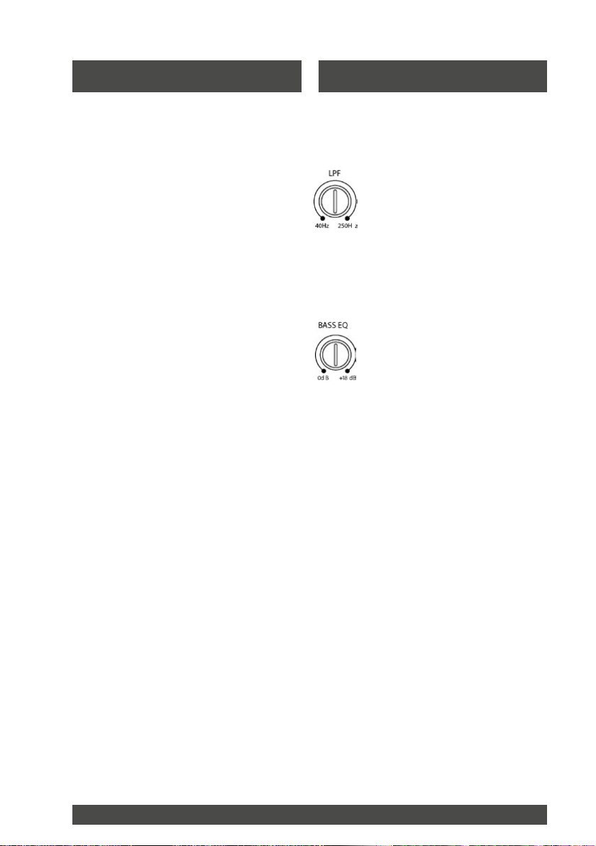
5. LPF (Low Pass Filter) Control
Einstellung der Frequenzen zwischen 40
und 250 Hz. die wiedergegeben werden
sollen. Eine Einstellung um die 40 Hz. Wird
nur die tiefsten Frequenzen wiedergeben,
hingegen eine Einstellung auf oberhalb 100
250 Hz einen eher "punchigen" Bass
hervorruft der allerdings auch ortbar werden
kann.
6. BASS EQ Control
Dieser EQ Schaltkreis wird benutzt um die
Tiefbasswiedergabe in Abhängigkeit der
Fahrzeuggröße bei 45 Hz nach dem persönlichen Geschmack zu verstärken. Denken Sie
daran, wenn Sie den Regelbereich von
+18 dB ausschöpfen muss der Verstärker die
10fache Leistung aufbringen.
5. LPF (Low Pass Filter) Control
This lter allows low pass of frequency and
is adjustable from 40Hz to 250Hz. A setting
of 40Hz will produce only low frequencies
(deep bass). A setting of 250Hz will allow the
amplier to produce a more punchy (higher)
bass response.
6. BASS EQ Control
This equalization circuit is used to enhance
the low frequency response of the vehicles
interior. With up to 18dB of boost centered at
45Hz the Bass EQ can be adjusted to meet
your own personal taste. Please note by
boosting the Bass EQ to its full +18dB you
are asking the amplier to work 10 times
harder!
5
Page 7

Ausstattung
Features
7. STATUS Indicator
Wenn die rote LED leuchtet ist eine
Schutzschaltung aktiv. Das deutet auf ein
Problem in Verbindung mit dem System und
Verstärker oder der Verkabelung hin.
Schauen Sie in die Fehlerbehebung.
8. POWER Indicator
Die grüne LED leuchtet, wenn der Verstärker eingeschaltet- und die Verkabelung
in Ordnung ist.
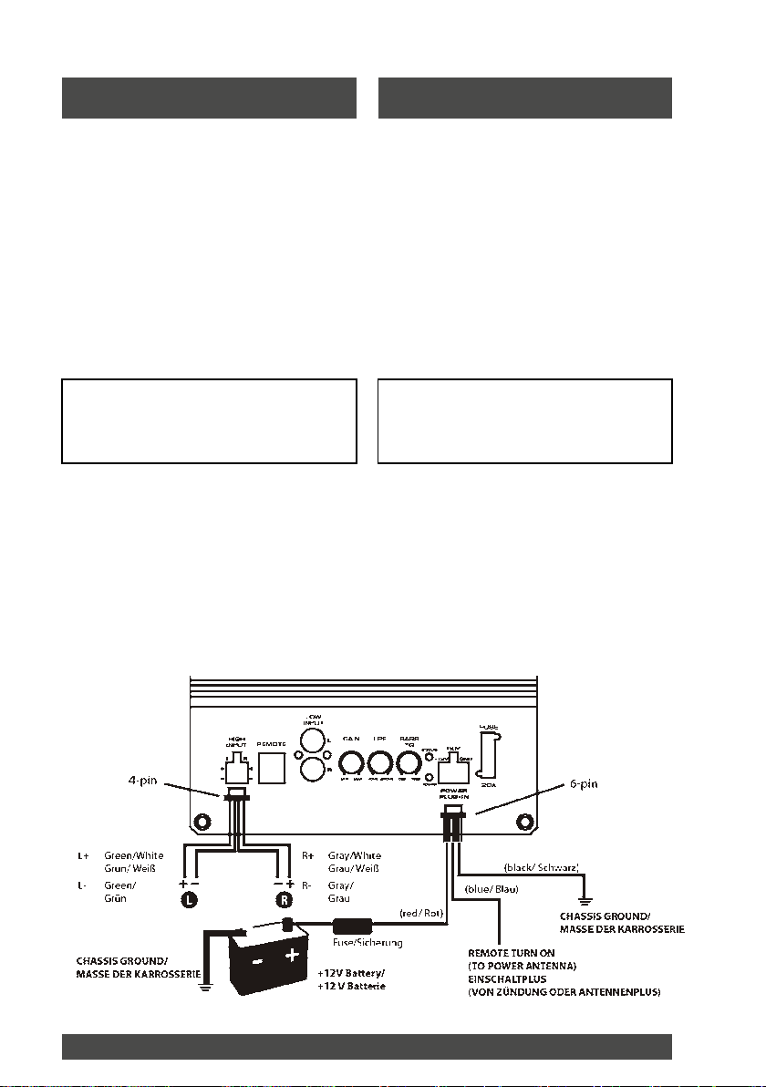
9. POWER PLUG-IN Connector
Dieser 6-polige Stecker beinhaltet die Kabel
für + 12V, Masse und Einschaltplusleitung.
10. FUSE 20A
Dieser Verstärker benutzt eine herkömmliche
Autoachsicherung. Nach einer eventuellen
Störung tauschen Sie diese nur gegen eine
Sicherung mit gleichem Wert (20A-gelb)
aus. Ein überbrücken der Sicherung kann
zu schweren Beschädigungen führen und
damit auch zum Erlöschen der Garantie.
7. STATUS Indicator
This RED L.E.D. glows only when the builtin
protection circuitry is activated. This indicates
a problem with the system in relation to the
amplier and/or wiring (see Troubleshooting
Tips).
8. POWER Indicator
This GREEN L.E.D. lights up when the power
is on and the system is wired correctly.
9. POWER PLUG-IN Connector
This 6-pin Molex style connector is where the
wiring harness plugs in for the power (+12V),
ground (GND) and remote turn-on (REM) wires.
10. FUSE 20A
For convenience the amplier uses a
common automotive ATC type fuse. For
continued protection in the event a fuse
blows, replace only with 20 Amp (Yellow
ATC) fuse. Substitution or deletion of the
fuse will void the product warranty and may
cause damage to your car or the amplier.
Einbau und Verkabelung
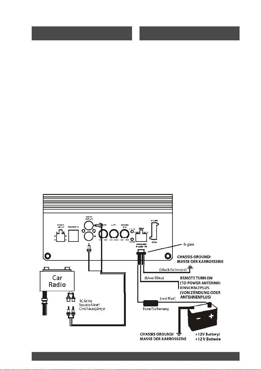
+12V Stromanschluss
Verbinden Sie die 2 roten Leitungen mit dem
Pluspol der Batterie. Um die Leitungen zu
verlängern benutzen Sie unbedingt Kabel
vom mindestens dem gleichen Querschnitt
oder dicker. Verlegen Sie das Kabel durch
eine Gummitülle in den Motorraum. Falls
keine Gummitülle vorhanden ist, installieren
Sie nachträglich eine. Verlegen Sie niemals
das Kabel ungeschützt an Fahrzeugblechen.
Installation and wiring
+12V Power connection
Connect the two twisted Red wires to 12
Volt positive. To lengthen the wire harness
splice at least 12 gauge wire (10 gauge for
runs longer than 10 feet) directly to th
battery. Route the wire through a rubber
grommet in the vehicles rewall. If there is
no factory grommet available, you will need
to install one.
6
Page 8
Einbau und Verkabelung Installation and wiring
Installation and wiring
REM
Connect the single blue wire to the radio
power antenna lead or remote output. This
wire is responsible for turning the amplifier
on and off. If the source unit (radio) is not
equipped with a Remote lead you can
connect this wire to an accessory or ignition
point at the vehicle fuse block.
In this type of installation, the amplifier will
be on whenever the ignition is on. To
lengthen this wire use at least 18 gauge wire
and run it with exactly the same care and
attention as the +12V power cable.
GND
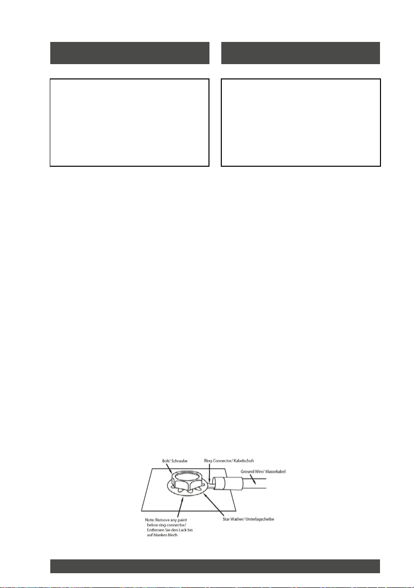
Connect the two-twisted Black wires directly
to the chassis of the vehicle. The length of
these wires should be kept to an absolute
minimum and should be terminated to bare
metal using a ring terminal. Should you
need to lengthen the wire harness use the
same gauge wire as was run for the positive
12 Volt connections as noted above.
CAUTION!
The power fuse on the amplifier
chassis is to protect the amp
against overdrive. To protect the
vehicles electrical system, an
additional 20A fuse must be used
within 18-inches of the battery on
the +12V cable.
ACHTUNG!
Die Sicherung am Verstärker dient
nur zur Absicherung desselben gegen
Überlastung. Um das Fahrzeug und
den Kabelbaum zu schützen müssen
Sie eine 20A Sicherung höchstens 30
cm hinter dem Batterieanschluss in
die Plusleitung einfügen.
REM
Verbinden Sie die blaue Leitung mit dem
Remote- oder Antennenplus Ihres Radios.
Über diese Leitung wird der Verstärker
angeschaltet, sobald hier +12V anliegen.
Falls Ihr Radio keinen solchen Anschluss
hat, können Sie diese Leitung auch an die
Zündung oder an eine Zubehörleitung
anschließen, In diesem Fall wird der
Verstärker immer angeschaltet, sobald die
Zündung an ist. Verlängern Sie diese
Leitung im Bedarfsfall nur mit einer Leitung
gleichen Querschnitts oder dicker.
GND
Verbinden Sie die zwei schwarzen Leitungen direkt mit der Fahrzeugkarosserie.
Die Leitung sollte so kurz wie möglich
gehalten werden. Verschrauben Sie die
Leitung nur auf blankem Metall. Eventuelle Grundierungen oder Lack sollten
Sie vorher vom Blech entfernen. Verlängern Sie diese Leitung im Bedarfsfall
nur mit einer Leitung gleichen Querschnitts
oder dicker.
CAUTION!
The power fuse on the amplier
chassis is to protect the amp against
overdrive. To protect the vehicles
electrical system, an additional 20A
fuse must be used within 18-inches
of the battery on the +12V cable.
REM
Connect the single blue wire to the radio
power antenna lead or remote output. This
wire is responsible for turning the amplier
on and off. If the source unit (radio) is not
equipped with a Remote lead you can
connect this wire to an accessory or ignition
point at the vehicle fuse block. In this
type of installation, the amplier will be
on whenever the ignition is on. To lengthen this wire use at least 18 gauge wire
and run it with exactly the same care and
attention as the +12V power cable.
GND
Connect the two-twisted Black wires directly
to the chassis of the vehicle. The length of
these wires should be kept to an absolute
minimum and should be terminated to bare
metal using a ring terminal. Should you
need to lengthen the wire harness use the
same gauge wire as was run for the positive
12 Volt connections as noted above.
7
Page 9
Einbau und Verkabelung Installation and wiring
Low Level Eingang und RCA Inter-
connect -Anschluss
Bei Radios mit Cinchausgängen müssen
Sie die Cinchausgänge mit den Cinchein-
gängen des MOVE 10-300A/ 12-400A
verbinden. Benutzen Sie hierfür eine
Stereocinchleitung mit entsprechender
Länge. Diese Leitung ist nicht Bestandteil
des Lieferumfangs. Achten Sie beim
verlegen des Cinchkabel auf gute Führung
möglichst entfernt von stromführenden
Kabeln, da die Einstreuungsgefahr und
somit ein späteres eventuelles Stören des
Verstärkers hiermit im Vorfeld verhindert
werden kann. Vermeiden Sie auf jeden Fall
ein paralleles Verlegen. Im Idealfall sind
Stromkabel und Cinchkabel jeweils
getrennt auf einer Fahrzeugseite zu
verlegen.
INPUT SIGNAL
Wählen des Cinch- oder Lautsprecher-
ausgangs
Verbinden Sie das Radio entweder mit dem
High Level(Lautsprechereingang) oder
Low Level(Cincheingang) des MOVE 10-
300A / 12-400A Eingangs. Der Cinch-
ausgang des Radios (sofern vorhanden)
wird die bessere Qualität des Signals
liefern, da es nicht erst eine Verstärkerstufe
des Radios durchlaufen muss.
ANMERKUNG: Benutzen Sie niemals
beide Eingänge gleichzeitig.
Bei Radios mit nur Lautsprecherausgängen
(Wie die meisten Werksradios). Verbinden
Sie die Leitungen des 4 Pin Steckers mit
den Lautsprecherausgängen des Radios.
Achten Sie auf richtige Polarität, da sich
ansonsten das Signal auslöschen würde
und kein Bass zu hören ist. Eine andere
Möglichkeit ist das Signal z.B. an den
hinteren Lautsprechern abzugreifen.
INPUT SIGNAL
Choosing the High or Low Inputs
The MOVE 10-300A/ 12-400A input signal
connects to the head unit's High Level
(speaker wire) output OR Low Level (RCA)
output provided the radio is so equipped
with Line Out. A dedicated subwoofer or low
level signal will deliver the best perfor-
mance. If unavailable use the high level
inputs, as will be the case with most factory
head units.
NOTE: Never use BOTH High and Low
L evel inputs at the same time. You must
se lect one or the other!
For radios with only speaker outputs
(including most Factory source units). Using
the 4-pin Molex style wiring harness
provided, splice directly into the radio's
speaker outputs. Be sure to maintain proper
speaker polarity.
Another option is to tap off the existing front
or rear full range speakers.
Einbau und Verkabelung
Installation and wiring
Low Level Eingang und RCA Inter-
connect -Anschluss
Bei Radios mit Cinchausgängen müssen
Sie die Cinchausgänge mit den Cinchein-
gängen des MOVE 10-300A/ 12-400A
verbinden. Benutzen Sie hierfür eine
Stereocinchleitung mit entsprechender
Länge. Diese Leitung ist nicht Bestandteil
des Lieferumfangs. Achten Sie beim
verlegen des Cinchkabel auf gute Führung
möglichst entfernt von stromführenden
Kabeln, da die Einstreuungsgefahr und
somit ein späteres eventuelles Stören des
Verstärkers hiermit im Vorfeld verhindert
werden kann. Vermeiden Sie auf jeden Fall
ein paralleles Verlegen. Im Idealfall sind
Stromkabel und Cinchkabel jeweils
getrennt auf einer Fahrzeugseite zu
verlegen.
Low Level Input and RCA Interconnect
Wiring
For radios that have RCA line outputs. You
will need to connect the low-level RCA style
inputs from the MOVE 10-300A/ 12-400A to
the line-outputs from the radio (source) via
an RCA interconnect commonly called a
“stereo patch cord”. Choose the correct
length and style of RCA interconnects for
your needs. Be extra careful when routing
your RCA audio interconnect cables. Car
environments are notorious for poorly
insulated wires. This means that hiss,
engine noise and fan noise can be easily
picked up through RCA cables if run
incorrectly. Take care to make sure the
power and audio signal are not on the same
side of the vehicle and they do not cross
each other.
Einbau und Verkabelung
Installation and wiring
INPUT SIGNAL
Wählen des Cinch- oder Lautsprecherausgangs
Verbinden Sie das Radio entweder mit dem
High Level(Lautsprechereingang) oder
Low Level(Cincheingang) des MOVE 10300AR/ 12-400AR Eingangs. Der Cinchausgang des Radios (sofern vorhanden)
wird die bessere Qualität des Signals
liefern, da es nicht erst eine Verstärkerstufe
des Radios durchlaufen muss.
ANMERKUNG: Benutzen Sie niemals
beide Eingänge gleichzeitig.
Bei Radios mit nur Lautsprecherausgängen
(Wie die meisten Werksradios). Verbinden
Sie die Leitungen des 4 Pin Steckers mit
den Lautsprecherausgängen des Radios.
Achten Sie auf richtige Polarität, da sich
ansonsten das Signal auslöschen würde
und kein Bass zu hören ist. Eine andere
Möglichkeit ist das Signal z.B. an den
hinteren Lautsprechern abzugreifen.
INPUT SIGNAL
Choosing the High or Low Inputs
The MOVE 10-300AR/ 12-400AR input signal
connects to the head unit's High Level
(speaker wire) output OR Low Level (RCA)
output provided the radio is so equipped
with Line Out. A dedicated subwoofer or low
level signal will deliver the best performance. If unavailable use the high level
inputs, as will be the case with most factory
head units.
NOTE: Never use BOTH High and Low
Level inputs at the same time. You must
select one or the other!
For radios with only speaker outputs (including most Factory source units). Using
the 4-pin Molex style wiring harness
provided, splice directly into the radio's
speaker outputs. Be sure to maintain proper
speaker polarity. Another option is to tap off
the existing front or rear full range speakers.
8
Page 10
Einbau und Verkabelung Installation and wiring
Low Level Input and RCA Interconnect
Wiring
For radios that have RCA line outputs. You
will need to connect the low-level RCA style
inputs from the MOVE 10-300A/ 12-400A to
the line-outputs from the radio (source) via
an RCA interconnect commonly called a
“stereo patch cord”. Choose the correct
length and style of RCA interconnects for
your needs. Be extra careful when routing
your RCA audio interconnect cables. Car
environments are notorious for poorly
insulated wires. This means that hiss,
engine noise and fan noise can be easily
picked up through RCA cables if run
incorrectly. Take care to make sure the
power and audio signal are not on the same
side of the vehicle and they do not cross
each other.
Installation and wiring
Low Level Eingang und RCA Interconnect-Anschluss
Bei Radios mit Cinchausgängen müssen
Sie die Cinchausgänge mit den Cincheingängen des MOVE 10-300AR/ 12-400AR
verbinden. Benutzen Sie hierfür eine
Stereocinchleitung mit entsprechender
Länge. Diese Leitung ist nicht Bestandteil
des Lieferumfangs. Achten Sie beim
verlegen des Cinchkabel auf gute Führung
möglichst entfernt von stromführenden
Kabeln, da die Einstreuungsgefahr und
somit ein späteres eventuelles Stören des
Verstärkers hiermit im Vorfeld verhindert
werden kann. Vermeiden Sie auf jeden Fall
ein paralleles Verlegen. Im Idealfall sind
Stromkabel und Cinchkabel jeweils
getrennt auf einer Fahrzeugseite zu
verlegen.
Low Level Input and RCA Interconnect
Wiring
For radios that have RCA line outputs. You
will need to connect the low-level RCA style
inputs from the MOVE 10-300AR/ 12-400AR
to the line-outputs from the radio (source) via
an RCA interconnect commonly called a
“stereo patch cord”. Choose the correct
length and style of RCA interconnects for
your needs. Be extra careful when routing
your RCA audio interconnect cables. Car
environments are notorious for poorly
insulated wires. This means that hiss,
engine noise and fan noise can be easily
picked up through RCA cables if run
incorrectly. Take care to make sure the
power and audio signal are not on the same
side of the vehicle and they do not cross
each other.
9
Page 11

Bedienung und Einstellung Operation and adjustments
Drehen Sie den Regler komplett auf
40Hz. Dann drehen Sie den Regler
bis Sie den erwünschten Sound
erreicht haben. Dies sollte in
Kompaktfahrzeugen und Kombis bei
etwa 70 Hz 100 Hz, bei Limousinen
bei ca. 90 Hz 150 Hz. der Fall sein.
Eine vernünftige Einstellung die sich in den
Rest der Anlage und der Musik einfügt wird
empfohlen. Stellen Sie sicher, das die
Tonregelung Ihres Radios neutral ist.
Bass EQ Adjustment
Dieses Feature dient zur Tiefbassanhe-
bung um einen kraftvolleren Sound zu
bekommen. Speziell in kleinen Fahr-
zeugen macht dieses Feature Sinn,
da durch den kleineren Innenraum ein
übertragen des Tiefbasses abnimmt.
Sie können den Tiefbass bei 45 Hz um
bis zu 18 dB verstärken. Setzen Sie
diese Regelung vorsichtig ein. Eine
Regelung bis zum Maximum von + 18 dB
fordern sowohl Verstärker als auch Sub-
woofer bis an die Grenzen und können zur
Turn the crossover LPF adjustment
all the way down to 40Hz. Then slowly
turn the knob up until desired sound is
achieved. Normal listening level
should be right around 100Hz to
150Hz. Use common sense when
adjusting the crossover. When
properly adjusted, the bass from the MOVE
10-300A/ 12-400A should blend in with the
rest of your speakers and not overpower the
music. Be sure to set the tone controls of
your radio (source unit) to flat while dialing
in the crossover.
Bass EQ Adjustment
This special feature is designed to
provide you with more powerful sound
quality and it allows you to increase
the Bass up to +18dB. Keep in mind
that more is not always better.
Adjusting the control to the MAX
(18dB) position will stress the
amplifier and the woofer which could result
in damage.
Bedienung und Einstellung
Operation and Adjustments
SET UP ADJUSTMENTS
Your MOVE 10-300A/ 12-400A uses
several controls to provide sonic integration
with virtually any vehicles unique acoustic
properties. Please read the following
section carefully to familiarize yourself with
the function of each control.
The following adjustment sequence is
recommended to properly tune your MOVE
10-300A/ 12-400A. By first adjusting the
GAIN, then the LPF, followed by the BASS
EQ (in this order) will give you the best
results.
Input GAIN Control
This control allows you to match the input
level of the amplifier to the output level of
your head unit. Matching the input can be
accomplished in four simple steps:
1. Make sure the remote gain control
is not plugged in until after the master
gain control is set.
2. Set the GAIN control on the
amplifier to MIN (completely counter
clock wise).
Operation and Adjustments
EINSTELLUNGEN
Ihr MOVE 10-300AR/ 12-400AR hält mehrere
Einstellmöglichkeiten bereit um ihn
akustisch perfekt auf Ihr Fahrzeug abzustimmen. Lesen Sie bitte den nächsten
Abschnitt um sich mit den verschiedenen
Einstellmöglichkeiten vertraut zu machen.
Die nachfolgende Einstellreihenfolge erleichtert Ihnen die korrekte Anpassung an Ihr
Fahrzeug und Ihren Hörgeschmack. Durch
Einstellen des GAIN, dann LPF danach des
Bass EQ wird das beste Ergebnis erzielt.
GAIN
Dieser Regler erlaubt Ihnen die Anpassung
des Eingangspegels auf den Ausgangspegel des Radios. Die korrekte Einstellung
erfolgt in 4 einfachen Schritten.
1. Stellen Sie sicher, das die Remoteleitung zum Anschalten des Verstärkers nicht eingesteckt / verbunden istn
bzw. das Radio abgeschaltet ist.
2. Drehen Sie den GAIN Regler ganz
nach links auf MIN.
3. Schalten Sie nun das Radio ein.
Stellen Sie sicher, das die Bass- und
Höhen/Mittenregelung des Radios
ausgeschaltet bzw. auf 0 steht. Stellen Sie
nun die Lautstärke des Radios auf etwa 2/3
der Maximallautstärke ein.
4. Drehen Sie den GAIN Regler nun im
Uhrzeigersinn bis der Sound leicht verzerrt.
Drehen Sie nun den GAIN Regler wieder
leicht zurück bis die Verzerrungen weg
sind.NOCHMALS: Denken Sie daran das der
GAIN Regler KEIN Lautstärkeregler ist.
Nichtbeachtung der oben genannten
Schritte kann zu Beschädigungen des
Woofers oder des Verstärkers führen.
LPF (Low Pass Filter) Weicheneinstellung
Da der persönliche Musikgeschmack differiert, sollten Sie die Einstellung des LPF
vornehmen, während Sie sich Musik Ihrer
Wahl anhören.
SET UP ADJUSTMENTS
Your MOVE 10-300AR/ 12-400AR uses
several controls to provide sonic integration
with virtually any vehicles unique acoustic
properties. Please read the following
section carefully to familiarize yourself with
the function of each control. The following
adjustment sequence is recommended
to properly tune your MOVE 10-300AR/
12-400AR. By rst adjusting the GAIN,
then the LPF, followed by the BASS EQ (in
this order) will give you the best results.
Input GAIN Control
This control allows you to match the input
level of the amplier to the output level of
your head unit. Matching the input can be
accomplished in four simple steps:
1. Make sure there
mote gain control
is not plugged in
until after the master
gain control is set.
2. Set the GAIN control on the
amplier to MIN (completely counter
clock wise).
3. Turn on the head unit and adjust
the volume to 2/3 maximum, and set
the BASS and TREBLE on the radio
(source) to zero or at.
4. Turn the GAIN control clockwise until the
sound just begins to distort, then back off
slightly to cut distortion and operate at
optimum gain.Remember, the GAIN control
is not a volume control. Ignoring these four
steps above may leave you with a damaged
woofer and/or damaged amplier.
LPF (Low Pass Filter) Crossover Adjustment
Since musical tastes vary, adjust the crossover by ear while listening to the music
of your choice.
10
Page 12
Bedienung und Einstellung Operation and adjustments
Turn the crossover LPF adjustment
all the way down to 40Hz. Then slowly
turn the knob up until desired sound is
achieved. Normal listening level
should be right around 100Hz to
Operation and Adjustments
Turn the crossover LPF adjustment
all the way down to 40Hz. Then slowly
turn the knob up until desired sound is
achieved. Normal listening level
should be right around 100Hz to
150Hz. Use common sense when
adjusting the crossover. When
properly adjusted, the bass from the MOVE
10-300A/ 12-400A should blend in with the
rest of your speakers and not overpower the
music. Be sure to set the tone controls of
your radio (source unit) to flat while dialing
in the crossover.
Bass EQ Adjustment
This special feature is designed to
provide you with more powerful sound
quality and it allows you to increase
the Bass up to +18dB. Keep in mind
that more is not always better.
Adjusting the control to the MAX
Operation and Adjustments
Drehen Sie den Regler komplett auf 40Hz. Dann
drehen Sie den Regler bis Sie den erwünschten
Sound erreicht haben. Dies sollte in Kompaktfahrzeugen und Kombis bei etwa 70 Hz 100 Hz,
bei Limousinen bei ca. 90 Hz 150 Hz. der Fall
sein. Eine vernünftige Einstellung die sich in den
Rest der Anlage und der Musik einfügt wird
empfohlen. Stellen Sie sicher, das die
Tonregelung Ihres Radios neutral ist.
Bass EQ Adjustment
Dieses Feature dient zur Tiefbassanhebung um einen kraftvolleren Sound zu
bekommen. Speziell in kleinen Fahrzeugen macht dieses Feature Sinn, da durch
den kleineren Innenraum ein übertragen
des Tiefbasses abnimmt. Sie können den
Tiefbass bei 45 Hz um bis zu 18 dB verstärken. Setzen Sie diese Regelung vorsichtig
ein. Eine Regelung bis zum Maximum
von + 18 dB fordern sowohl Verstärker
als auch Subwoofer bis an die Grenzen
und können zur Beschädigung führen.
Bemerkung: Obwohl dieses Tuningwerkzeug zu guten Ergebnissen führt,
müssen u.U. ander Einstellungen wieder
verändert werden, da jede Einstellung
wieder die anderen beeinusst. Falls
notwendig sprechen Sie Ihren autorisierten
ETON Händler an der Ihnen weiterhilft.
Remote Gain Controller
Ihr Eton MOVE 10-300AR/ 12-400AR
Subwoofer wird mit einer kabelgebundenen
Lautstärkefernregelung ausgeliefert. Diese
Fernbedienung nutzt als Anschlusskabel
eine Standard Telefonkabel mit RJ45 Verbindungen.Diese sind an beiden Seiten
gleich und das Kabel damit verwechslungssicher. Stecken Sie einfach ein Ende
in den integrierten Subwooferverstärker,
verlegen Sie das Kabel und stecken Sie
dann das andere Ende in die Fernbedienung. Montieren Sie die Fernbedienung
im Armaturenbrettbereich oder Mittelkonsole.
Turn the crossover LPF adjustment all the way
down to 40Hz. Then slowly turn the knob up until
desired sound is achieved. Normal listening
level should be right around 100Hz to
150Hz. Use common sense when
adjusting the crossover. When pro perly adjusted, the bass from the
MOVE 10-300AR/ 12-400AR should
blend in with the rest of your speakers and not
overpower the music. Be sure to set the tone
controls of your radio (source unit) to at while
dialing in the crossover.
Bass EQ Adjustment
This special feature is designed to
provide you with more powerful
sound quality and it allows you to
increase the Bass up to +18dB.
Keep in mind that more is not al
ways better. Adjusting the control to
the MAX (18dB) position will stress the ampli-
er and the woofer which could result
in damage.
NOTE: Although this adjustment sequence
will in most cases provide the best tuning
results, the actual process may include
several readjustments of each of the
controls since their settings interact with
each other. If necessary, consult your
Authorized ETON dealer for help tuning
your system.
Remote Gain Controller
Your ETON MOVE 10-300AR/ 12-400AR includes a wired Remote Subwoofer Gain control module. It uses standard telephone wire
and telephone RJ45 connectors. To connect
the Remote Subwoofer Gain control to the
amplied enclosure, simply insert one end
of the telephone plug into the REMOTE gain
port. Plug the other end into the back of the
remote module. Mount the module within
easy reach or under your dash.
11
Page 13

Bedienung und Einstellung
Operation and adjustments
Einspielzeit
Um das Optimum aus Ihren Woofer heraus
zu holen raten wir eine sogenannte
Einspielphase von mindestens 40 Stunden
(ca. 2 Wochen bei normaler Nutzung)
einzuhalten. Während dieser Zeit sollten
Sie den Woofer mit ca. einem Drittel der
Maximallautstärke einspielen lassen.
Fehlerbehebung
Power LED leuchtet nicht
Prüfen Sie folgendes mit einem
Spannungsmessgerät:
• +12 Volt (Rote Leitung, Anschluss stecker und Batteriel (sollte zwischen
• +12V DC und +16V DC anzeigen)
Remote Einschaltplus (blaues Kabel sollte zwischen +12V DC und +16V DC
anzeigen)
• Masseanschluss Überprüfen des
Kontaktes. Ist der Kontakt blank?
Power LED leuchtet grün aber kein Ton
• Überprüfen Sie die Cinchverbindnung
• Testen Sie die Lautsprecherausgänge
mit einem anderen Lautsprecher von
dem Sie wissen, das er funktioniert.
• Testen Sie den Subwoofer mit einem
anderen Radio von dem Sie wissen
das es funktioniert.
• Messen Sie auf dem Cinchkabel in der
Stellung Wechselspannung AC ob eine
Spannung (Signal) anliegt.
Break In Period
To get the most from your woofer we
recommend a "break-in" period of at least
40 hours (typically 2 weeks) at no more than
1/3 of maximum volume. During this time
the cone and spider assembly will gradually
break in resulting in greater performance
and more listening enjoyment.
Trouble shooting
Power LED not ON
With a Volt OHM Meter (VOM) check:
• +12 Volt power terminal (should read
+12 to +16VDC)
• Remote turn-on terminal (should read
+12 to +16VDC)
• Ground Terminal
Power LED lights GREEN, no output
• Check RCA connections
• Test speaker outputs with known good
speakers
• Substitute known good Source Unit
• Check for signal on the RCA cable with
VOM in AC position
12
Page 14

Fehlerbehebung Trouble shooting
Power LED leuchtet grün aber
Lautstärke reduziert automatisch
• Schutzschaltung ist aktiviert aufgrund
von Überhitzung des Verstärkers.
Sollte dieser Fehler auftauchen
verändern Sie die Einbauposition des
Woofers, sodass genug Luftzirkulation
vorhanden ist.
• Überhöhte Temperatur kann aus
falscher Einstellung der Eingangs-
empndlichkeit resultieren. Führen Sie
die Gain Einstellung wie beschrieben
erneut durch (bzw. regeln Sie die
Empndlichkeit zurück).
Rote Status Störung LED leuchtet,
kein Ton und
1. Verstärker ist sehr heiß
2. Verstärker schaltet ab wenn der
Motor läuft
3. Verstärker spielt nur mit sehr
geringer Lautstärke
• Thermoschutzschaltung ist aktiv.
Überprüfen Sie auf korrekte Impedanz
an den Lautsprecherausgängen.
Überprüfen Sie die Belüftung des
Verstärkers.
• Spannungsschutzschaltung ist aktiv.
Spannung am verstärker ist nicht
zwischen +10 - +16 V DC. Prüfen Sie
die Ladespannung der Batterie bzw.
der Lichtmaschine.
• Kurzschluss Schutzschaltung ist aktiv.
Überprüfen Sie ob die Lautsprecher leitungen vom Radio kommend
gegenseitig oder gegen Fahrzeug masse kurz geschlossen sind.
Lautsprecher arbeiten unter dem
Impedanzminimum. Überprüfen Sie ob
nicht noch ein Werksverstärker (unter
dem Sitz oder hinter einer Kofferraum verkleidung) zwischen geschaltet ist.
Power LED lights GREEN, but volume
reduces automatically
• Advanced Protection Circuitry is
engaging due to high internal
temperature of the amplifier. Amplifier
requires more air flow around the
chassis. If this continues choose a
better ventilated mounting location.
• High operating temperature can be
caused by incorrect input sensitivity
level. Reset the GAIN control.
Red Status Protection LED is ON, no
output and
1. Amp is VERY HOT
2. Amp shuts down ONLY when the
vehicle is running
3. Amp plays at very low volume
• Thermal protection is engaged. Check
for proper impedance at speaker
terminals. Also check for adequate
airflow around the amplifier.
• Voltage protection engaged. Voltage to
the amp is not within the 10-16 VDC
operating range. Have the battery/
charging system inspected.
• Short circuit protection is engaged.
Check for speaker wires shorted to
each other or the vehicle chassis.
Speakers operating below the
minimum impedance can cause this to
occur.
13
Page 15

Fehlerbehebung
Trouble shooting
Drehzahlabhängiges Brummen oder
Pfeifen oder ähnliche Geräusche
• Überprüfen Sie auf fehlerhaftes oder
gequetschtes Cinchkabel
• Überprüfen Sie die Verlegung des
Cinchkabels.
• Überprüfen Sie die Signalquelle (Radio)
auf ausreichende Masseverbindung
• Überprüfen Sie die Empfindlichkeits einstellung und regeln diese ggf.
zurück.
Schlechter / Wenig Basspegel
• Überprüfen Sie die Polarität der
angeschlossenen Lautsprecherleitungen
vom Radio kommend. Erhöht sich der
Pegel bei nur einer angeschlossenen
Leitung, dann entsprechend eine
Leitung verpolen.
Technische Daten / Specications
Membrandurchmesser (mm)
Bauhöhe (mm)
Membrane diameter (mm)
Overall height (mm)
Alternator noise (varies with RPM)
• Check for damaged RCA cable.
• Check routing of RCA cable
• Check Source Unit for good ground
• Check amp gain setting, turn down if
set too high
Poor Bass Response
• Check speaker polarity, reverse the
connection of one speaker only.
250 / 300
130
RMS power
Mittl.Kennschalldruck 1W / 1mtr.
Anzahl Spulen
Impedanz pro Spule
Membranmaterial
Korbmaterial
Spulendurchmesser (mm)
RMS power
Efciency 1W / 1mtr.
Number of voice coils
Impedance per voice coil
Membrane material
Basket material
Voice coil diameter (mm)
14
1 x 300 W
88 dB
1
1 x 4 Ohm
reinforced paper cone
metal basket
50
Page 16

ETON behält sich das Recht vor, die beschriebenen Produkte ohne jegliche Vorankündigung zu verändern oder zu verbessern. Alle Rechte sind vorbehalten. Die auch teilweise
Vervielfältigung des vorliegenden Handbuchs ist untersagt.
ETON reserves the rigth to make modications or improvements to the products illustrated without notice thereof. All rights belong to the respective owners. Total or partial
reproduction of this User‘s Guide is prohibited.
 Loading...