

OPERATING MANUAL
ALPHA 89
HF LINEAR POWER AMPLIFIER
ALPHA/POWER, INC. RF Power for Communications and Industry
14440 Mead Court – Unit B, Longmont, Colorado 80504
(970) 535-4173 * FAX (970) 535-0281

TABL
E OF CON
TENTS
INSTALLING YOUR ALPHA 89 ................................................. 1
OPERATING YOUR ALPHA 89 .................................................. 2
1.0 - INTRODUCTION ...................................................................................................................3
2.0 - OVERVIEW OF AMPLIFIER CAPABILITIES ......................................................................3
3.0 -ALPHA 89 SPECIFICATIONS ................................................................................................4
4.0 - UNPACKING AND PREPARATION ..................................................................................... 5
Figures 1-3 Transformer installation ................................................................................................6
Figure 4 Inside top view ..................................................................................................................7
Figure 5 View with front panel lowered ........................................................................................... 8
5.0 CONTROL & INDICATOR FUNCTIONS ................................................................................9
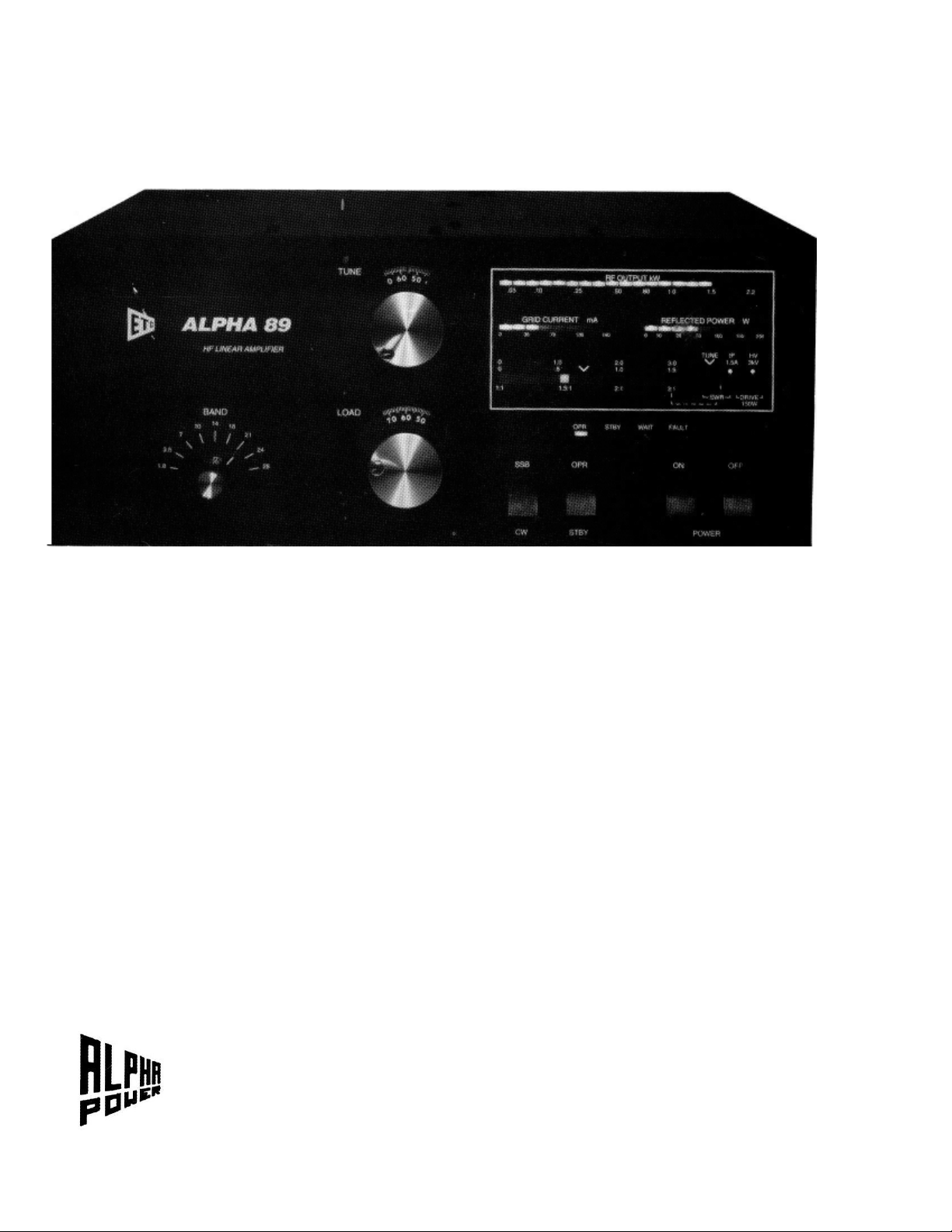
Figure 6 Front Panel .......................................................................................................................10
6.0 - INSTALLATION ...................................................................................................................11
Figure 7 Rear panel connections .....................................................................................................11
7.0 - OPERATION .........................................................................................................................12
Table Tuneup Settings ....................................................................................................................14
8.0 - FAULTS AND PROTECTIVE FUNCTIONS ........................................................................15
9.0 - TROUBLESHOOTING SUGGESTIONS ..............................................................................16
10.0 -ALPHA 89 FUNCTIONAL CONFIGURATION .................................................................17
ILLUSTRATIONS
Figs. 1-3, Transformer installation ...................................................................................................6
Fig. 4, Inside top view .....................................................................................................................7
Fig. 5, View with front panel lowered ..............................................................................................8
Fig. 6, Front panel view .................................................................................................................10
Fig. 7 Rear panel connections ........................................................................................................11
Fig. 8, ALPHA 89 Simplified schematic ................................................. .......................................18

CA
UTION! !
1
READ BEFORE PROCEEDING!
TO AVOID SERIOUS DAMAGE NOT COVERED UNDER
WARRANTY READ THIS MANUAL CAREFULLY BEFORE
INSTALLING YOUR ALPHA 89
The ALPHA 89 is easy to install, but failure to carry out each procedure exactly as described in this manual is likely to
lead to amplifier damage which is not covered under warranty. Damage to other station equipment also may result.
Important precautions are given on this and the next page.
INSTALLING YOUR ALPHA 89
1. Be careful not to twist or warp the chassis when handling the amplifier with its cover removed. Never lift the chassis
by one comer when the transformer is in place.
2. When installing or removing the transformer, move carefully and follow the instructions in this manual exactly. When
installing, insure that all connectors are properly mated and fully seated. Don't force them! Tuck the transformer handle out
of the way so it doesn't interfere with the cover. It is necessary to install at least one of the transformer bolts to eliminate
potentially hazardous voltage buildup between the transformer and chassis.
When removing the transformer, carefully unlock the mated connectors and gently pull them apart.
3. Insure that both tubes are solidly seated in their sockets with the red silicone rubber chimneys firmly seated against
the chassis.
4. Connect the green conductor in the ALPHA 89 power cord only to the power source neutral or ground. Connecting
the green wire to a "hot" line is almost certain to cause immediate damage. Triple check your wiring before plugging
in!
5. Make sure the primary power tap is connected to the tap closest to your actual AC line voltage. See manual section 4.3.
6. Never install cover screws longer than 1/4". Longer screws may penetrate internal boards or wiring and cause severe
damage. Make sure each screw hole in the cover is aligned with its corresponding captive nut in the chassis before inserting
screws.
7. Remove blower motor shipping hardware from rear chassis wall. Save the two 10-32 bolts, fiber washers, and rubber
shim; reinstall this hardware whenever the chassis is transported.
8. Solidly bond all station equipment together. Heavy braid, such as the outer conductor of RG-8/U coaxial cable, is
recommended for the purpose. This is important for personal and equipment safety as well as to avoid RF feedback.
9. DON'T apply AC power with the cover off without contacting ETO customer service first. You may damage both
you and your amplifier!
101193

C
A
U
T
I
O
N
! !
89 requires only 50 watts drive for full rated output. Virtually all
ALPHA
y, most modem transceivers maintain quite consistent output from band
Setting the transceiver POWER or RF PWR control IS NOT SUFFICIENT
also is
781,
nnect and ground antenna feedlines, and to disconnect AC power, when the equipment is not in
2
READ BEFORE PROCEEDING!
TO AVOID SERIOUS DAMAGE NOT COVERED UNDER
WARRANTY READ THIS MANUAL CAREFULLY
BEFORE OPERATING YOUR ALPHA 89
The ALPHA 89 is easy to operate, but failure to carry out each procedure exactly as described in this manual is likely to
lead to amplifier damage which is not covered under warranty. Damage to other station equipment also may result.
Important precautions are given on pages 1 and 2 of this manual.
OPERATING YOUR ALPHA 89
1. You must set transceiver power output properly! The ALPHA
damage results directly from severe overdrive. Damage caused by applying far more than rated drive power to the
89 will not be covered under warranty. Fortunatel
to band and mode to mode if set up properly.
Several popular transceivers can generate RF spikes of 200-300W or more unless the transceiver internal drive level
adjusted carefully according to its manufacturer's instructions. Typically this is done with a knob labeled DRIVE (ICFT 1000), PROCESSOR OUT (TS-940, TS-950) or, on SSB when speech processing is not in use, MIC or MIKE.
2. The ALPHA 89 "faults" into STBY or OFF when unsafe operating conditions occur. If this happens the fault can be
cleared by removing excitation, switching from operate to standby and back to operate, and then re-applying excitation.
3. To operate the ALPHA 89 efficiently, cleanly, and safely at any desired peak power output, it must be properly loaded
and driven for that power level. If peak power output (and hence drive) is to be changed significantly, the amplifier must
be reloaded and tuned. See section 7.
4. Induced energy from nearby electrical storms or other power transients may damage components.
Such damage is not covered under warranty. It is important to use a good lightning arrestor, and it's
good practice also to disco
use.
HAPPY OPERATING!

1.0
-
INTRODUCTION
101193
3
2.0
-
OVERVIEW OF AMPLIFIER CAPABILITIES
This Manual provides all the information necessary to install and operate your ALPHA 89. Sche matic diagrams are availa ble on request, at no charge to owners. For your own protection please
return the Owner Registration Card immediately and advise ETO of any future address change
promptly.
1.1 - OWNER ASSISTANCE
Assistance is available from ETO Customer Service (Communications Products) at (719) 599-3861,
260-1191, by FAX at (719) 260 -0395, or by mail. ALPHA technical specialists also may be contact
through the same office.
It is extremely important to thoroughly review Installation and Operation sections of this manual
before attempting to use the ALPHA 89. Failure to do so could result in serious damage not covered
under warranty.
The ALPHA 89 is capable of 1.5 kW continuous RF output on all commonly-used modes and on any
authorized amateur frequency from 1.8 to 29.7 MHz.
The ALPHA 89 is compatible with all popular amateur BF transceivers and exciters. It requires
approximately 50 watts peak RF drive for 1.5 kW output.
The ALPHA 89 is capable of full break-in CW (QSK) and all digital modes when used with any
appropriate transceiver. The ALPHA 89 control system incorporates protective functions that minimize the probability of accidental damage to the amplifier or its power tubes. In most cases, when
one of the protective functions is "tripped," a front panel LED indicator will display the fault (e.g.,
excessive grid or plate current, load reflected power/ VSWR, etc.)
For extended RATT or other very high duty cycle service, use of the ALPHA 89 optional auxiliary
cooling fan, available from ETO, is strongly recommended. With reasonable care, your ALPHA 89
should provide exceptional performance and satisfaction for many years.

3.0
-
ALPHA 89
SPECIFICATIONS
4
Frequency Coverage: All amateur bands 1.8-29.7 MHz* plus most non-amateur frequencies 6.0-19.0
MHz and 20-30 MHz.
* NOTE: FCC rules do not permit new amateur amplifiers to be operable on 24-30 MHz as delivered within the U.S.
& possessions. Owners who send ETO Customer Service a photocopy of their autho rizing amateur license will
promptly be provided information on "unlocking" 12 and 10 meter coverage.
Band Change & Tuning: Manually controlled by the operator.
Power Output: 1500 watts PEP, keyed CW or continuous carrier, no time limit. Auxiliary
cooling fan (optional) recommended for high duty cycle continuous operation.
Drive Power: Typically 50-60 watts for full rated output
Input VSWR: < 1.5:1 within amateur bands; < 2:1 elsewhere.
Tube Complement: Two Eimac 3CX800A7 triodes in grounded grid.
T/R System: Heavy duty PIN diode switch. Switching time approximately 1 mS. Enclosed
mechanical bypass relay.
ALC: Grid-current-derived, adjustable to -lOV maximum.
Harmonic Output: Better than 55 dB below rated output.
Intermodulation: Better than 36 dB below rated output.
Fault Protection: Plate overcurrent, grid overreurrent, high reflected power (load VSWR), T/R
mis-sequencing, gain (i.e., severe mistune or RF are), overdrive, other.
Displays: Dedicated LED bargraphs for peak Pout, Prefl, and lg, plus switched bargr aph for average
Ip, HV, TUNE indicator, drive power, and load VSWR.
Cooling: Full cabinet ducted-air, rear intake/top exhaust Floating blower mount for quietest
operation.
Primary Power: 190-250V (200, 220, 240V nominal taps), 50-60 Hz, single phase; fused 20A.
Size & Weight: 17.3"W x 7"H x 16.5"D (439 x 178 x 419 nun) excluding controls, feet &
connectors; 75 lb. (34 kg) net.

4.0 - UNPACKING AND PREPARATION (Ref. figs. 1-4, pages 6-7)
5 7
4.1 Unpack amplifier and transformer. Inspect both for physical damage. Save all packing material for
future use. Warning! Do not ship amplifier in other than factory packing or equivalent.
4.2 Remove cover by removing all screws except the two located in the perforated tube exhaust areas.
Inspect carefully for shipping damage. If damage is discovered in either of these two steps notify ETO
Customer Service immediately.
4.3 Connect the proper internal line voltage tap. The ALPHA 89 may be operated from any AC power
source of 190-250V, 50-60 Hz, 20 ampere capacity. A 4-terminal barrier strip for tap selection is located
toward the back chassis wall to the left of the transformer. DO NOT MOVE the wire connected to the
terminal marked PRE If necessary, move the other wire to the tap (200, 220, or 240V) closest to your
nominal AC line voltage.
4.4 Install Transformer. Position amplifier flat on a table with the right side of the chassis facing forward
Install the transformer per Figures 1 through 3, using its sling handle. Use care not to pinch or damage
wiring or components. You may wish to have a helper steady the chassis during the following steps.
Align the threaded holes or captive nuts in the transformer base with corresponding chassis holes.
Taking care not to torque or twist the chassis, carefully extend it over the edge of the table just far
enough to loosely screw in at least one, and preferably both, of the two outside transformer mounting
bolts (1/4-20 hex head with flat washes, supplied). The following step is recommended but not
mandatory...
Do not stand the amplifier on edge or move it further over the table edge. Instead, rotate it so as to
extend the two inner transformer mounting holes, one at a time, over the table edge and loosely install the
bolts. Now center the transformer as much as possible so that both sides are well clear of metal work.
Orient the chassis as above while tightening all 4 bolts.
One of the transformer connectors plugs into the AC power wiring near the top/rear of the chassis center
partition, on the power supply side. The remaining two connectors plug into the top of the power supply
board immediately in front of the transformer. Proper mating of these connectors is obvious with
reasonable care; look first and make sure they match! (See Fig. 3 view A-A) Make certain the connectors are
properly mated and seated, but don't force them; they mate and latch easily.
4.5 Insure that both tubes are fully seated in their sockets with their red rubber chimneys firmly
contacting the chassis.
4.6 Make sure the HV crowbar works smoothly.
4.7 Replace the cover and carefully reinstall all screws. Be careful not to force or cross-thread screws.
Never use screws longer than 1/4"!
 Loading...