

Page 1

OPERATING INSTRUCTIONS
SECTIONAL DOOR OPERATOR
Page 2

Page 3
3
1. CONTENTS
1. Contents .................................................... 3
2. General instructions .................................. 3
3. Safety-related regulations ......................... 4
4. Safety instructions ..................................... 4
5. Mounting .................................................... 5
6. Initial operation .......................................... 6
7. Technical data ......................................... 11
8. Drawings .................................................. 12
9. Maintenance ............................................ 13
10. Transport, Storage, Disposal................... 13
11. Service, Spare parts, Accessories .......... 13
12. Declaration of conformity ......................... 14
13. Annex ...................................................... 15
2. GENERAL INSTRUCTIONS
2.1 Original operating instructions
This manual is the original manual.
Copyright protection: any reproduction is permitted
only with approval of the manufacturer.
Subject to alterations in the interest of technical pro-
gress.
All dimensions given in mm. The diagrams in this
manual are not to scale.
2.2 Intended use
The operator series SD, SW and SDA are intended for
driving loads that do not need to be secured against
falling, such as: weight counterbalanced sectional
doors.
For other applications of the operators, the manufacturer must be consulted.
2.3 Warranty
The function and safety of the equipment is only gua-
ranteed if the warning and safety instructions included
in these operating instructions are adhered to.
The manufacturer is not liable for injury to persons or
damage to property if these occur as a result of the
warnings and safety advice being disregarded.
The CE declaration and the warranty will void if components are changed.
Only original spare parts and by the manufacturer approved accessories shall be used. These parts are
used to maintain the quality and safety of the machine.
Changes are only permitted after consultation with the
manufacturer.
2.4 Target group
Only qualified and trained specialists are permitted to
mount the operator and perform mechanical maintenance.
Only qualified and trained electricians may connect
the operator and carry out the electrical maintenance.
Qualified and trained people have knowledge of general and specific safety and accident prevention regulations, the relevant regulations and standards, training
in the use and maintenance of adequate safety
equipment, as well as the ability to recognize hazards
associated with their work.
2.5 Key to symbols
DANGER !
Indicates a hazard with a high level of risk which, if not
avoided, will result in death or serious injury.
WARNING !
Indicates a hazard with a medium level of risk which, if
not avoided, could result in death or serious injury.
CAUTION !
Indicates a hazard with a low level of risk which, if not
avoided, could result in minor or moderate injury.
NOTICE !
Indicates an imminent danger of damage or destruction.
INFORMATION !
Reference to separate documents which must be complied with.
Page 4
4
3. SAFETY-RELATED REGULATIONS
For connecting, programming and servicing, the following regulations must be observed (the list is not exhaustive)!
Construction product standards:
EN 13241-1
EN 12445
EN 12453
EN 12635
EN 12978
Electromagnetic compatibility (EMC):
EN 55014-1
EN 61000-3-2
EN 61000-3-3
EN 61000-6-2
EN 61000-6-3
Machinery Directive:
EN 60204-1
EN 12100-1
Local protective regulations must be complied with.
4 SAFETY INSTRUCTIONS
DANGER !
Failure to observe the instructions in this document can
result in mortal danger!
DANGER !
Risk of death by electric shock!
When installing the operator, when opening housings
and work on electrical equipment, the operator has to
be disconnected from the power.
Observe the local safety regulations.
NOTICE !
To avoid damage to the operator and at the door, the
drive must be mounted only if :
the drive is undamaged,
the ambient temperature is -20 ° C to +60 ° C,
the installation site altitude does not exceed 1,000 m
above sea level.
The use of the operator, as well as the standard
cable is only allowed indoors.
For outdoor installation must be consulted with the
manufacturer.
WARNING !
Make sure that children can not access the door
control or the hand-held transmitter.
Ensure, before moving the door, that no persons or
objects within range of the door.
Test all existing emergency command devices.
Pay attention to possible crushing and shearing
points on the door system.
Never reach into a running gate, into the guide rail or
moving parts.
INFORMATION !
For drives with fixed connection a main switch with
appropriate building main fuse must be provided.
WARNING !
Before installation, ensure that:
the operator is installed with the intended covers or
guards,
all seals are correctly and
all glands and screws are tightened correctly.
Page 5
5
5. MOUNTING
5.1 Preparation
Check that the delivery is complete.
Check if all accessories for your installation situati-
on are present (e.g. console).
Check if the system has a suitable mains connec-
tion and a mains switch.
Remove all unnecessary components from the door
Remove all devices, which are not required after
installation of the drive system.
Before installation, ensure that the operator is not
blocked,
Before installation, ensure that the operator has
been newly prepared after a lengthy storage period,
Before installation, ensure that no other sources of
danger are present,
Before installation, ensure that the installation site
has been cordoned off over a wide area.
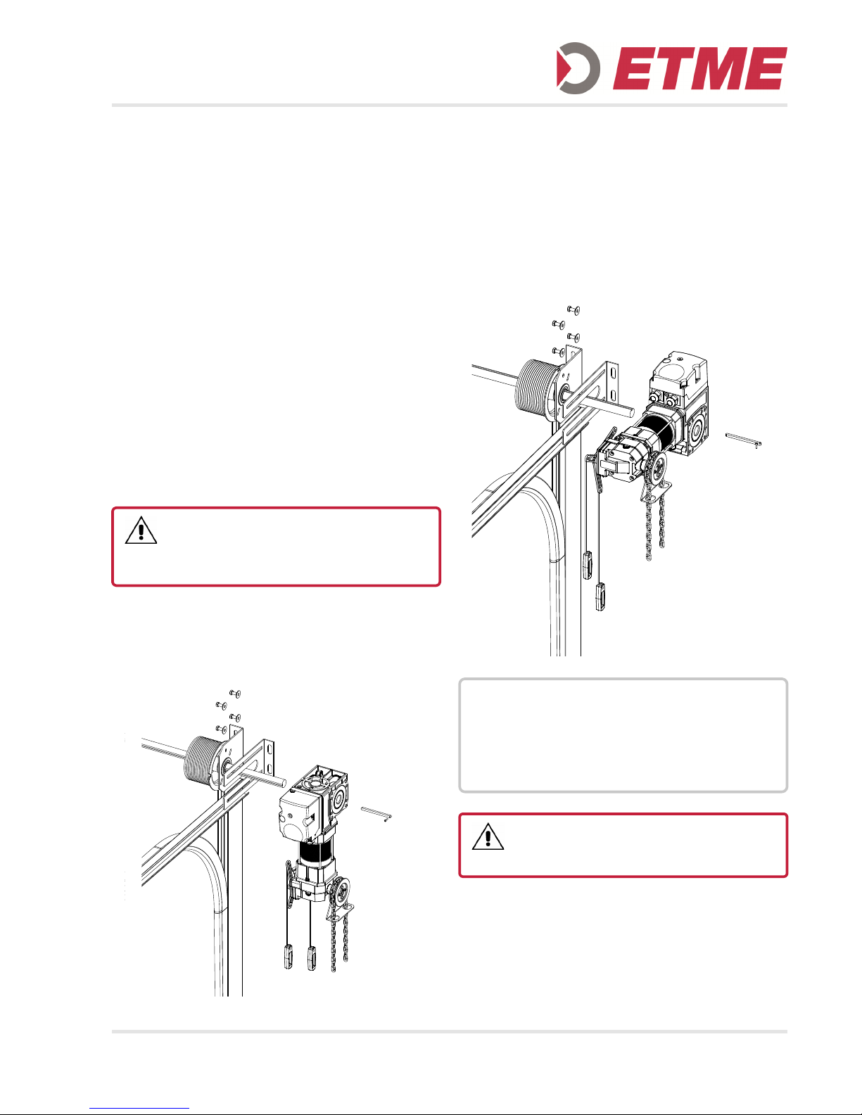
5.2 Mounting of the Operator
Install the torque bracket
Insert the feather key into the shaft
The shaft end is greased before fitting the drive
When using collars, slide the collar onto the shaft
Secure the feather key against sliding
Mounting operator in inverted position:
DANGER !
All components must be designed in relation to the
construction and the ground for the loads during tripping
of the safety catch device.
NOTICE !
To avoid damage to the operator and to the door, the
operator must be mounted with torque support bracket so that it is vibration dampened.
When mounting the operator do not carry or pull at
the cable.
DANGER !
With a continuous shaft groove the feather key has to
be secured against moving.
Page 6
6
6. INITIAL OPERATION
Power-operated doors shall be audited at least annually by a trained person, before first use and as required (with written proof).
The operator of the door system, shall be trained after
initial operation.
Before installation, ensure that the direction of rotation
of the gear motor is correct, and all protective devices
are active.
CAUTION !
For operators with weights greater than 20 kg additional
aids shall be used, such as hooks or ropes for securing
and lifting. On the drives corresponding eyes are provided.
INFORMATION !
The relevant instructions for the door must be observed
when fitting the operator to the door.
NOTICE !
To avoid damage to the drive, the following points must
be observed:
The types of cable and their diameters must be sel-
ected according to current regulations.
The nominal currents and the type of connection
must correspond to those on the motor type plate.
The drive details must agree with the connected
loads.
DANGER !
Danger of fatal electric shock!
Before commencing cabling works, you MUST disconnect the drive system from the mains supply. En-
sure that the electricity supply remains disconnected
throughout the cabling works.
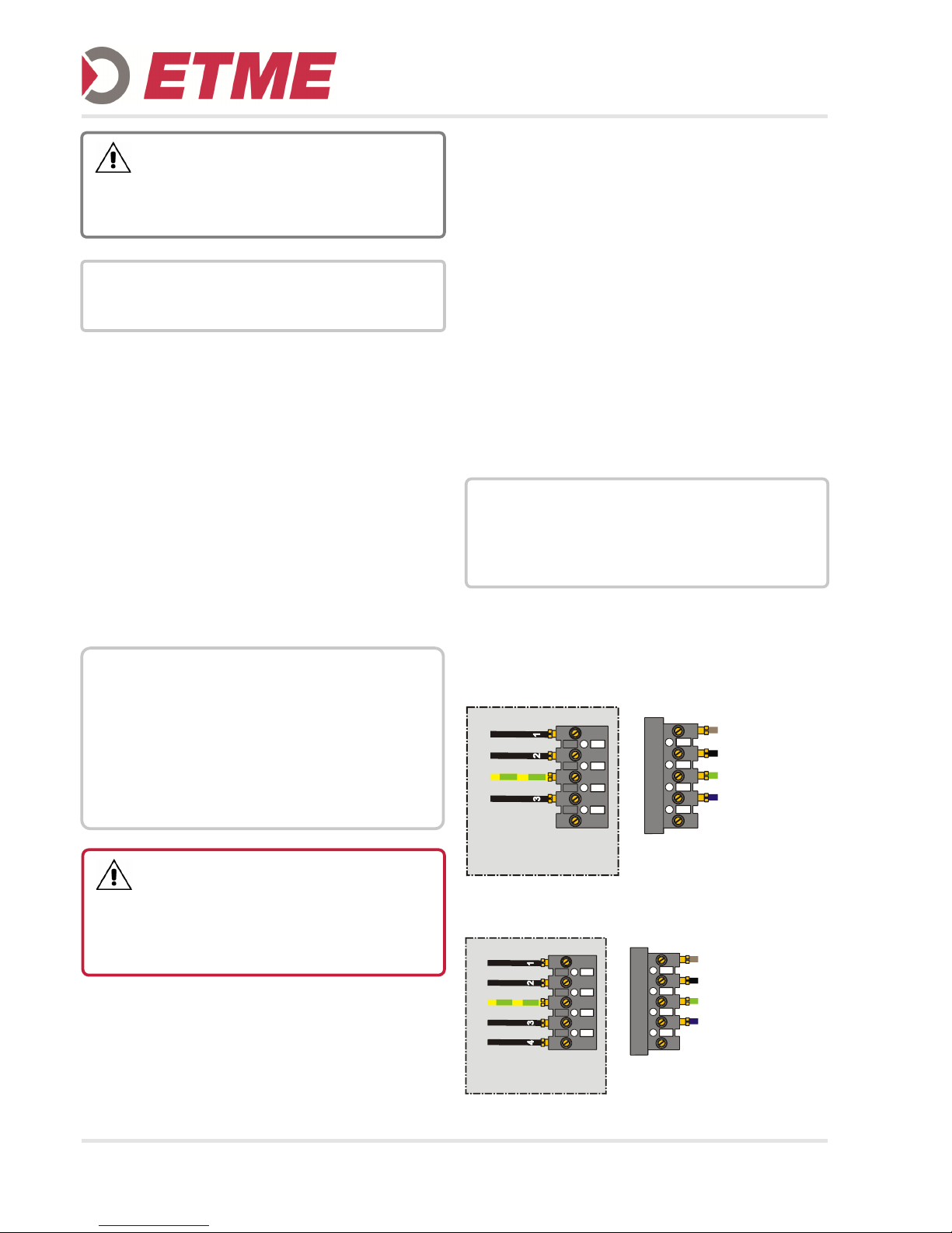
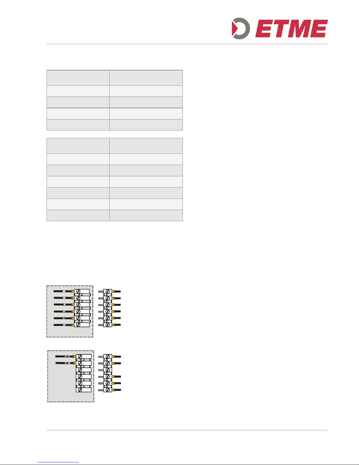
6.1 Connection to the control unit
The operator is factory wired to the control unit. If this
is not the case, proceed as follows:
Remove the cover from the operator.
Run the cable gland of the cable into the correspon-
ding fitting.
Connect the motor cable to the plug, the plug is po-
larized.
Connect the limit switch:
AWG: connect plug
Mechanical limit switch: connect according to dia-
gram
Attach the cover back on the operator.
Connection
Connection to cable set for mechanical limit switches:
Connection to cable set for electronic limit switches:
NOTICE !
When mounting the motor cables to ensure that the
individual wires are inserted deep enough and the
screws are tightened so that a firm connection is made.
This connection can be checked by pulling the cables.
Kabelsatz TAE
U1 = BN
PE
W1 = BL (BU)
V1 = SW (BK)
leer / empty
Kabelsatz TAE
U1 = BN
PE
W1 = BL (BU)
V1 = SW (BK)
leer / empty
Page 7
7
6.2 Mechanical limit switch
6.3 Connection
Terminal 2 is only available in version ME6. The safety
switch of the emergency hand operation system and
the thermo overload protection of the operator are
connected in series with the safety limit switches.
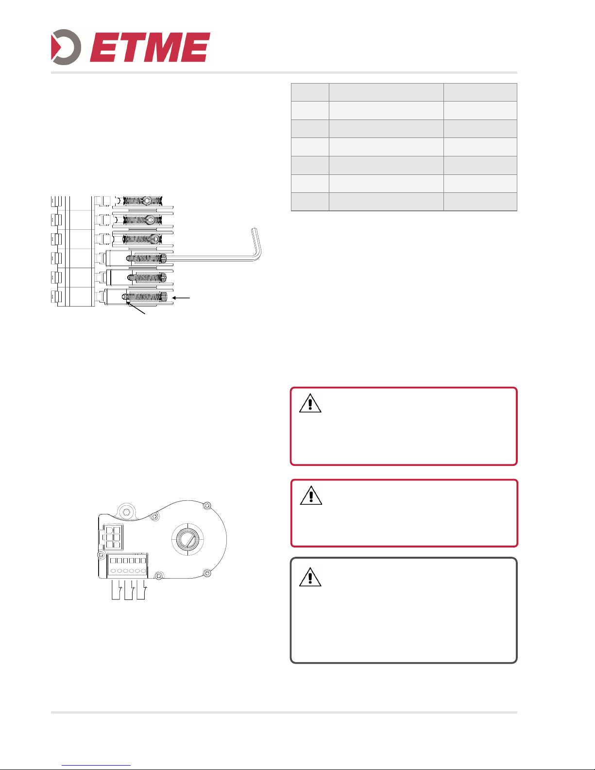
6.4 Setting the end positions: mechanical limit
switch
For the adjustment of the cam an Allen key size 2.5 is
required (included with the drive). The cam is fixed on
the correct switch position using the locking screw
after positioning (rough setting). Fine adjustment is
possible via the precision set screw.
To set the limit switch, the operator must be ready for
operation, completely mechanically fitted and electrically connected.
Before the first activation of the operator the door
should be in a center position to ensure there is suffi-
cient travel in both directions when starting.
On actuating the button OPEN, the door must open.
Otherwise the two phases L1 and L2 have to be
exchanged. To do this, control and drive must be disconnected from the main supply!
Setting the CLOSED end position
Bring the door in the CLOSED end position.
Set the cam so that the CLOSED limit switch is ac-
tuated.
Tighten the locking screw.
The Safety limit switch CLOSED must be set so
that it switches immediately when the limit switch
CLOSED is passed over.
Adjust the safety limit switch CLOSED.
Setting the OPEN end position
Bring the door in the OPEN end position.
Set the cam so that the OPEN limit switch is actua-
ted.
Tighten the locking screw.
The Safety limit OPEN switch must be set so that it
switches immediately when the limit switch OPEN
is passed over.
Adjust the safety limit switch OPEN.
Additional limit switches:
Bring the door to the desired position from the desi-
red direction (e.g. partial open position from the
position CLOSED).
Set the switch cam so that the additional limit
switch is actuated.
Tighten the locking screw.
C
L
O
S
E
D
O
P
E
N
Kabelsatz TAE
S
A
F
E
T
Y
A
U
X
.
L
I
M
I
T
N
O
/
N
C
Betriebsendschalter ZU
Betriebsendschalter AUF
Sicherheitsendschalter
COM
NCC
NOC
COM
NCC
Terminal 2
Zusatzendschalter 1
Zusatzendschalter 2
Kabelsatz TAE
C
L
O
S
E
D
P
r
e
l
i
m
i
t
C
l
o
s
e
COM
NCC
COM
NCC
COM
NCC
Terminal 1
Cam
(from outside in)
ME 4
(4 cams)
RED Safety limit switch open
GREEN Limit switch open
GREEN Limit switch close
RED Safety limit switch close
Cam
(from outside in)
ME 6
(6 cams)
RED Safety limit switch open
GREEN Limit switch open
GREEN Add. Limit switch 1
WHITE Limit switch close
RED Safety limit switch close
WHITE Add. Limit switch 2
Page 8
8
Correct the end positions
With the fine adjustment screw a readjustment of the
respective end position is possible.
Check of end positions
Check if the end positions are set correctly and if the
operator stops in the corresponding end position.
6.5 Connection of the electronic limit switch
The electronic (digital) limit switch is an absolute value
encoder.
It is connected via an RS485 interface to the control
unit. The encoder has a 6-pin connector on the serial
interface, which is connected to the control unit.
The safety switches of the operator are connected to
the terminals 7 - 12. Unused terminals must be equipped with a wire bridge.
6.6 Setting the end positions: electronic limit
switch
Please refer to the control unit operating manual for
instructions on setting the end positions.
6.7 Emergency operation
During maintenance works or in the case of an electrical fault, the door can be moved towards the OPEN or
CLOSED positions with the help of the emergency
operation equipment.
7
8 9 10
11 12
1
2
3
4
5
6
a
b
c
DANGER !
Serious injuries are possible due to uncontrolled door
movement!
To avoid personal injury, a safety catch device must be
mounted at the door (e.g. spring break device) if a operator with declutch system is used.
DANGER !
Serious injuries are possible due to uncontrolled door
movement!
Before releasing the maintenance declutch system the
door must be secured against falling.
WARNING !
Improper use may result in serious injury!
Emergency operation must only be carried out when
the motor is stationary.
The system must be disconnected from the power
supply during emergency operation.
Emergency operation must only be carried out from a
safe standing position.
Feststellschraube /
locking screw
Feineinstellschraube /
adjustment screw
Pin Assignment Color
1 Safety chain in Yellow
2 RS 485 B Green
3 0 VDC White
4 RS 485 A Pink
5 Safety chain out Grey
6 7 … 18 VDC Brown
Page 9
9
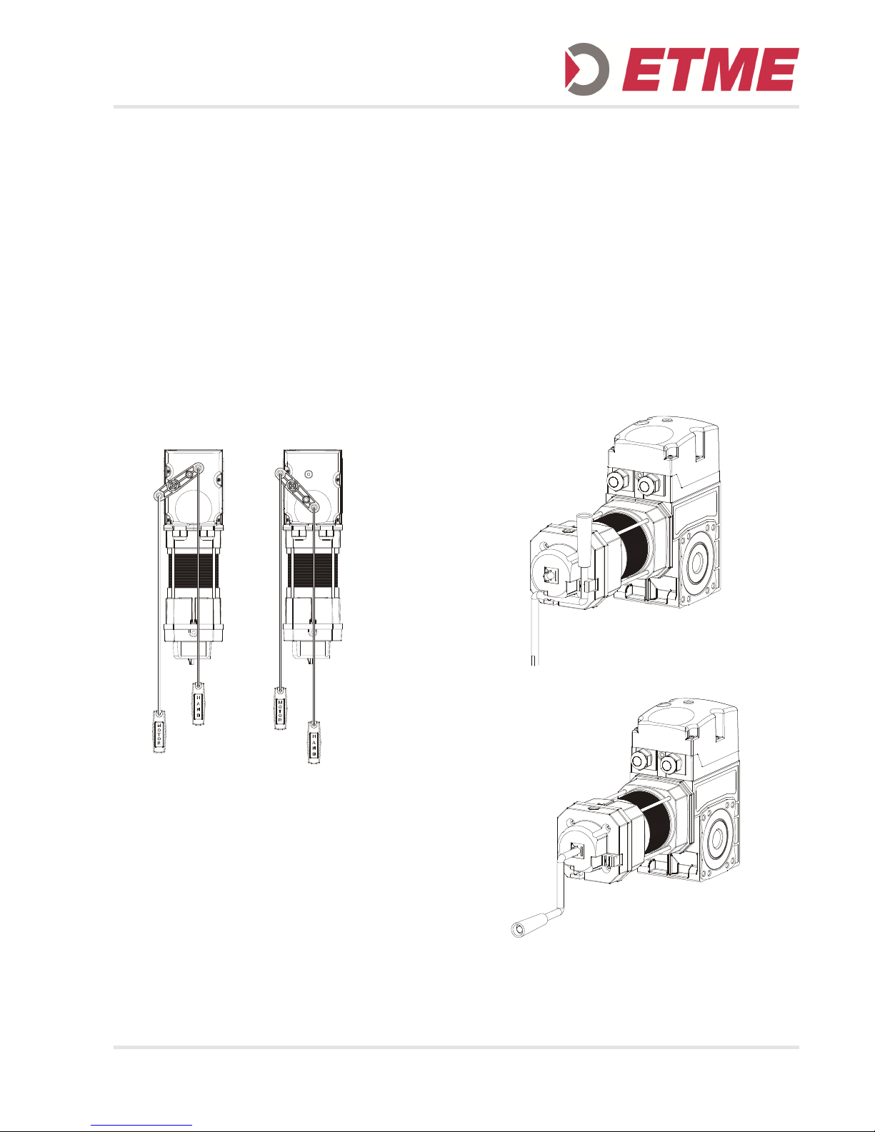
6.8 Declutch system
The mounting position of the actuator with unlocking is
preferably present in an inverted position (motor pointing downwards).
For mounting in an upright position, an additional cable guide is required!
The handles are for switching between motor and manual mode until.
1. Red handle - HAND (system coupled):
Switching to manual mode.
2. Open or close the door
3. Green handle - MOTOR- (system decoupled)
Switching to motor operation
4. The door can be operated again electrically
system decoupled system coupled
(motor operation) (manual operation)
6.9 Maintenance declutch system
For use as maintenance system, the release lever can
be fixed with a screw in the position for motor operating (decoupled).
For the purpose of maintenance, the screw can be
unscrewed and the drive can be disengaged. No actuation ropes are attached.
In addition, the drive will be equipped with a hand
crank or hand chain system for manual operation.
6.10 Hand crank
A insertion aid at the housing of emergency crank
handle facilitates the insertion of the crank.
1. Release the emergency hand crank from its fixing.
2. Insert the hand crank with slight pressure and a
little turning into the operator as far as it will go.
3. A micro switch is actuated and interrupts the ener-
gy supply to the motor via the safety circuit in the
control system.
4. Open or close the door using the hand crank.
5. If the crank is removed, the micro switch automati-
cally releases the control system. The door can be
operated electrically again.
Page 10
10
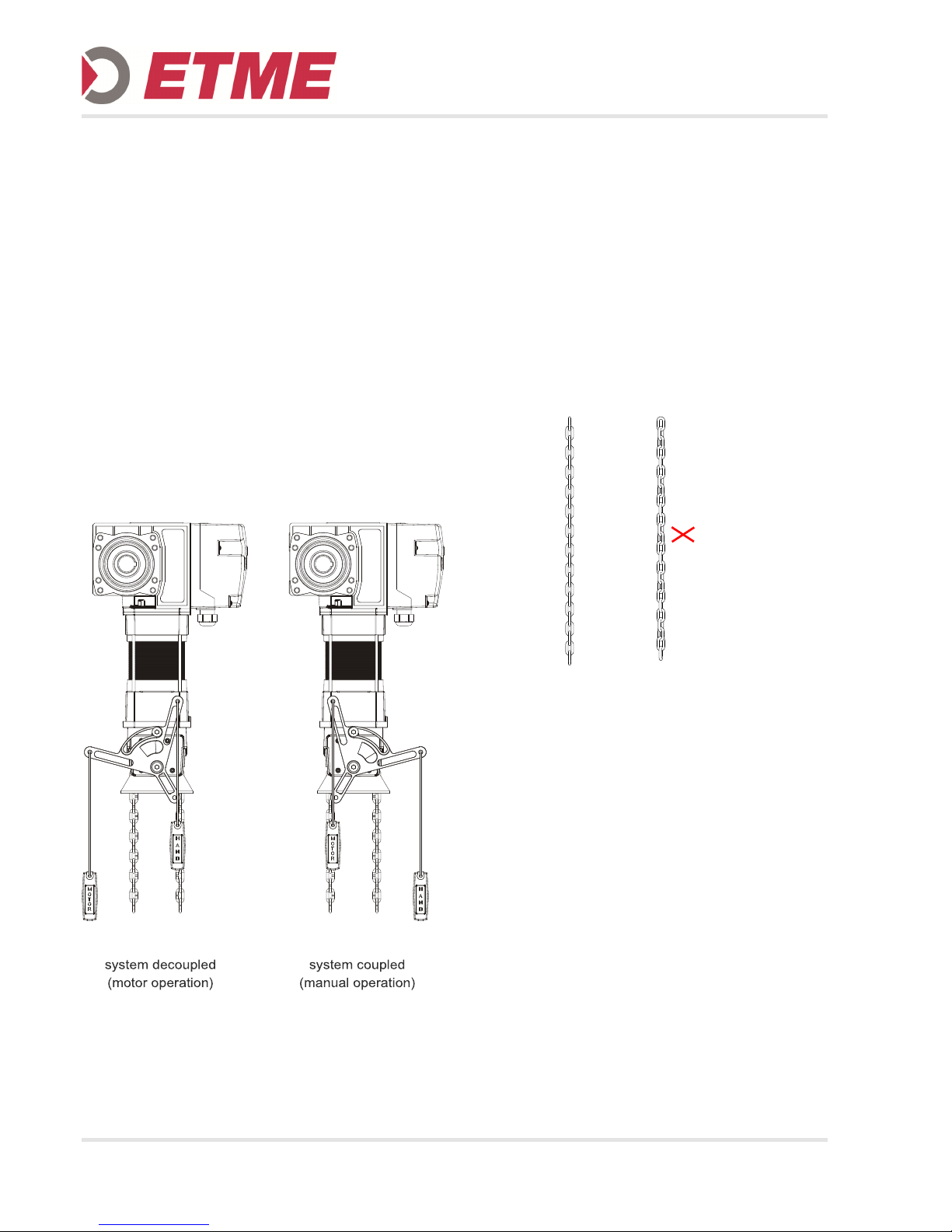
6.11 Hand chain
By pulling the release lever, the coiler shaft of the
hand chain system is shifted and thus switches
between motor- and manual operation.
When switching to manual mode a micro switch is actuated and interrupts the safety circuit. No motor operation is possible.
1. Red handle - HAND (system coupled):
Switching to manual mode
(the operating force is max. 390 N)
2. Open or close the door using the hand chain
3. Green handle - MOTOR- (system decoupled)
Switching to motor operation
(the operating force is max. 390 N)
4. The door can be operated again electrically
6.12 Extending or shortening the chain
The coil is joined via one or two coupling links (marked
by color yellow).
It can be opened at the coupling link and can be extended with a piece of chain and another coupling link.
When shortening, the respective part is to be separated from the coil chain using a bolt cutter. The coupling links must be carefully bent together.
When making changes to the coil chain, make sure
that the chain is not twisted when mounted.
chain not chain twisted
twisted
6.13 Rotate the hand chain system
The emergency chain system can be rotated by 180°
so that the coil wheel is on the other side.
To do this, the 4 fastening screws are unscrewed, the
housing is rotated by 180 ° and then re-tightened
(M=7Nm).
OK OK
Page 11
11
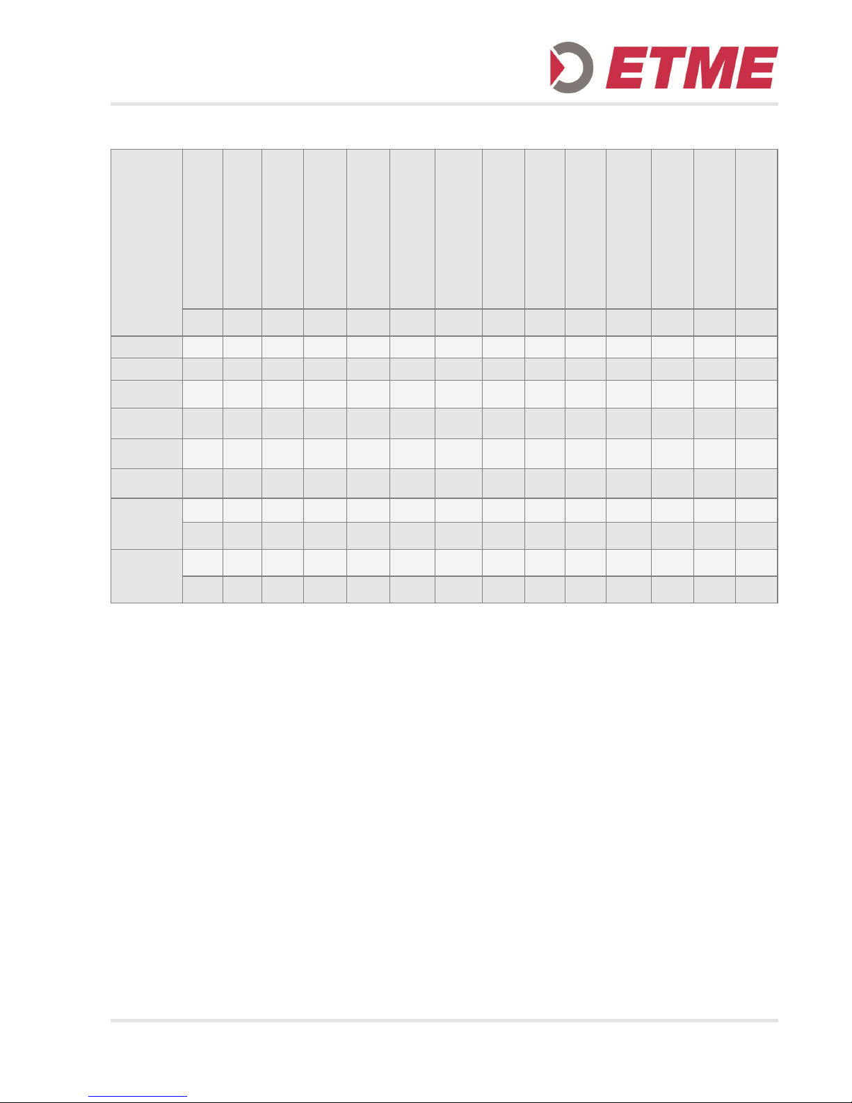
7. TECHNICAL DATA
1)
Limit ratio 20:1 respectively 40:1 available on request
2)
Keyway 6,35² mm (1/4“) – different hollow-shaft-Ø on request
For door gate systems with more cycles than usual, a
drive with 60% duty cycle should be chosen.
Antriebstype
Operator Type
Anlauf– Drehmoment
Staring Torque
Nenn– Drehmoment
Nominal Torque
Abtriebsdrehzahl
Output Speed
Haltemoment
Holding Torque
Endschalterbereich
1)
Limit capacity
1)
Hohlwellen Durchmesser
2)
Hollowshaft Diameter
2)
Betriebsspannung (50Hz)
Operating Voltage (50 Hz)
Motorleistung
Engine Output
Motoreinschaltdauer
Duty Cycle Engine
Betätigungen pro Stunde
Operating cycles per hour
Nenn – Strom bei 230 / 400V
Nominal Currentat 230 / 400 V
Art der Notbetätigung
Type ofmanualoperation
Schutzart
Protection Category
Gewicht
Weight
MA
[Nm]
MN
[Nm]
n2
[min
-
[Nm] i
Stw
D
[mm] U [V] P [kW]
S3
[%]
IN
[A]
IP
G
[kg]
SW-55.24 55 50 24 230 15 25,4 1~230 0,27 10 10 4,2 KU/ 54 12,0
SW-55.24-E 55 50 24 230 15 25,4 1~230 0,27 10 10 4,2 E 54 12,5
SD-100.24 100 80 24 230 15 25,4
3~230
3~400
0,37 40 20
2,6
1,5
KU/
KE
54 11,0
SD-100.24-E 100 80 24 230 15 25,4
3~230
3~400
0,37 40 20 2,6 1,5 E 54 11,5
SD-140.18 140 115 18 440 15 25,4
3~230
3~400
0,55 40 20 3,5 2,0
KU/
KE
54 12,0
SD-140.18-E 140 115 18 440 15 25,4
3~230
3~400
0,55 40 20 3,5 2,0 E 54 12,5
SD-130.24
130 100 24 230 15 25,4
3~230
3~400
0,55 60 25
3,5
2,0
KU/
KE
54 12,0
130 100 24 230 15 31,75
3~230
3~400
0,55 60 25
3,5
2,0
KU/
KE
54 12,0
SD-130.24-E
130 100 24 230 15 25,4
3~230
3~400
0,55 60 25
3,5
2,0
E 54 12,5
130 100 24 230 15 31,75
3~230
3~400
0,55 60 25
3,5
2,0
E 54 12,5
Page 12
12
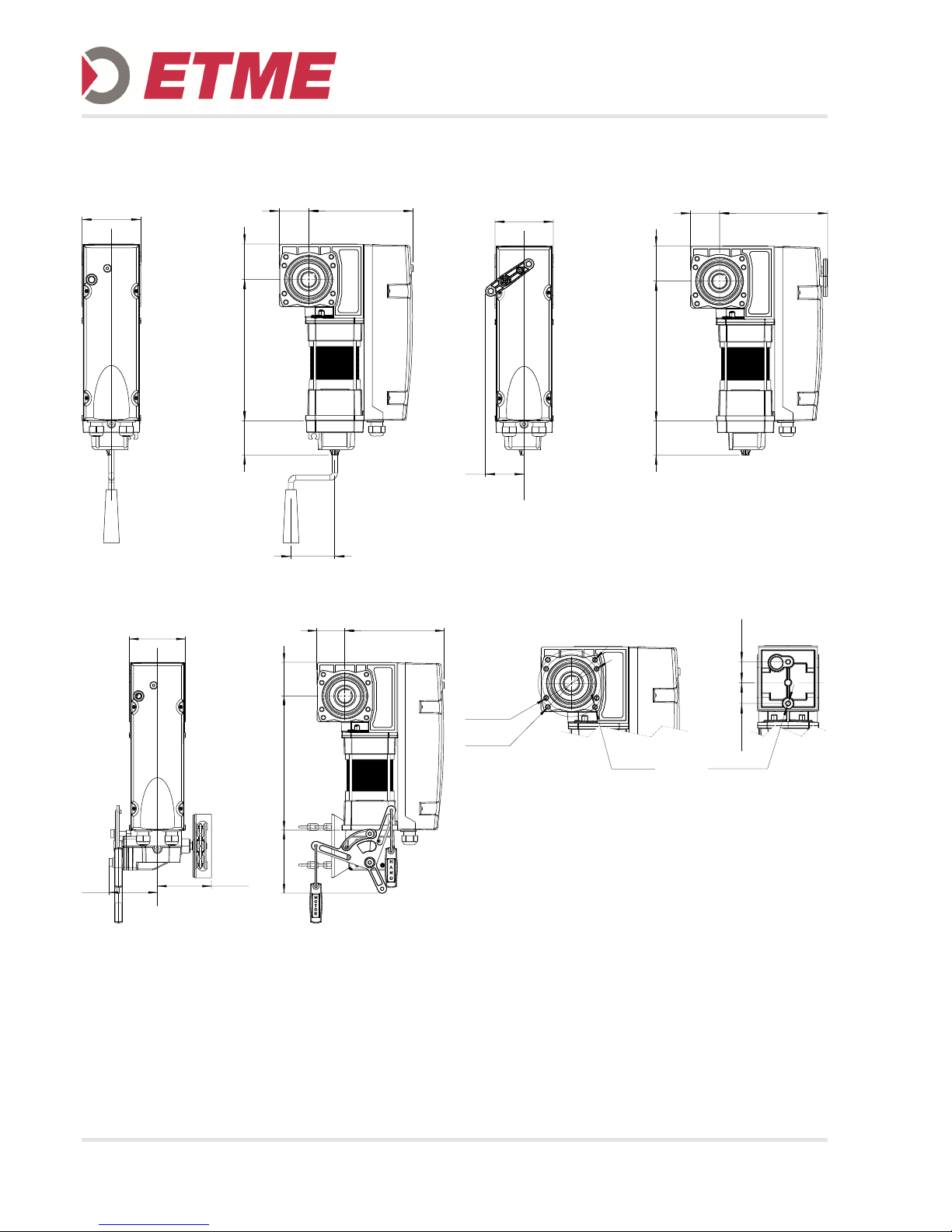
8. TECHNICAL DRAWINGS
Version KU
Version KE
Version E
Mounting points
110
82
55 196
6
6
,
5
2
6
4
6
4
95
106
110
55 196
6
6
,
5
2
6
4
1
2
4
73
110
55 204
6
6
,
5
2
6
4
6
4
3
7
,
5
0
3
7
,
5
0
M8x18 (2x)
Ø 120
Ø 105
M8x18
(8x)
Page 13
13
9. MAINTENANCE / ANNUAL INSPECTION
9.1 Gear unit
The gear unit has lifetime lubrication and is maintenance-free. The hollow shaft must be kept rust-free.
Check for noise and oil leakage.
9.2 Motor
The motor is maintenance free.
9.3 Fixtures
All fastening screws must be checked for tightness
and proper condition.
9.4 Cabling
Check power cord and cables regularly for damage
and insulation failure.
10. TRANSPORT, STORAGE, DISPOSAL
The drive has been fully assembled at the factory,
ready wired, tested and packaged.
To avoid damage, the transport or storage in the original packaging or equivalent make.
For the disposal of the national regulations must be
observed.
11. SERVICE, SPARE PARTS, ACCESSORIES
Only original spare parts and approved accessories
may be used. The use of non-original spare parts and
accessories may affect the functionality and the safety
of the system. For damages incurred thereby, any liability and warranty is excluded.
In the case of malfunctions which you can not easily
remedy yourself, please consult a specialist from the
manufacturer of the door system or another specialist
company.
DANGER !
Danger of fatal electric shock!
For maintenance of the operator, when opening hou-
sings and work on electrical equipment, the operator
is disconnected from the main power.
Observe the local safety regulations.
DANGER !
Serious injuries are possible due to uncontrolled door
movement!
Before releasing the maintenance declutch system the
door must be secured against falling.
NOTICE !
Only original spare parts and approved accessories
shall be used.
Changes are only permitted after consultation with
the manufacturer.
INFORMATION !
The maintenance of power-operated windows, doors
and gates must be performed only by authorized
persons who are familiar with the relevant maintenance and the national and local regulations.
INFORMATION !
Attention!
The gearbox contains oil. A proper disposal must be
ensured.
Page 14

14
12. DECLARATION OF CONFORMITY
We hereby declare that the products described below:
Sectional door operators of the model ranges SD, SW and SDA
are in conformity with the essential requirements of the Machinery Directive 2006/42/EC.
In addition, the partly completed machinery is in conformity with
the Construction Products Regulation (EU) No 305/2011
the Electromagnetic Compatibility Directive 2014/30/EU
the Low Voltage Directive 2014/35/EU
The following standards were applied:
EN 60204-1
EN 12100-1
DIN EN 12453
DIN EN 12604
EN 61000-6-2
EN 61000-6-3
EN 60335-1
EN 60335-2-103
Manufacturer and technical documentation management
ETME GmbH
Flohrstr. 33
D-13507 Berlin
The relevant technical documentation is compiled in accordance with Annex VII(B) of the Machinery Directive
2006/42/EC. We undertake to transmit, in response to a reasoned request by the market surveillance authorities,
this documentation in electronic form within a reasonable period of time.
The machinery is incomplete and must not be put into service until the machinery into which the partly completed
machinery is to be incorporated has been declared in conformity with the provisions of the Machinery Directive
2006/42/EC.
Place, Date
Berlin, 01.04.2016
Manufacturer’s signature
Konrad Machill
Technical Director
Page 15
15
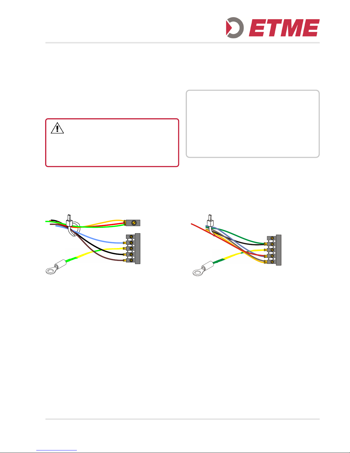
13. ANNEX - STAR, DELTA CONNECTION
The operator in the standard version is suitable as
three-phase motor for 230V/400V operation.
By rewiring is possible to switch the operator from the
factory star connection for 3 ~ 400V to the delta
connection for 3 ~ 230V.
The winding ends have to be rewired as shown below:
Star 3~400V
The nominal cross section of the wires in the terminal
is max. 2.5 mm2.
After reconnecting the rotation direction of the drive
has to be confirmed.
Delta 3~230V
DANGER !
Danger of fatal electric shock!
Before commencing cabling works, you MUST dis-
connect the drive system from the mains supply. Ensure that the electricity supply remains disconnected
throughout the cabling works.
NOTICE !
If the motor is wired to delta (3 ~ 230) ensure, that the
control unit and the mains power supply are adapted to
this voltage!
When reconnecting the motor cable to make sure that
the individual lines are inserted deep enough into the
connector and the screws are tightened properly
(torque max. 0.5 Nm). The connection can be checked
by gently pulling at the cable.
Sternpunktklemme
/ star point terminal
GE(YE) / RT (RD) / GN
U1 = BN
PE
W1 = BL (BU)
V1 = SW (BK)
leer / empty
U1 = BN / GE (YE)
PE
W1 = GN / SW (BK)
V1 = RT (RD) / BL (BU)
leer / empty
Page 16

► Rolltorantriebe
► Kettenradantriebe
► Sektionaltorantriebe
► Schnelllauftorantriebe
► Schiebetorantriebe
► Steuerungen
► Sicherheitssysteme
► Zubehör
ETME
PRODUKTE
► Operators for Roller Shutters
► Chain Wheel Operators
► Operators for Sectional Doors
► High-Speed Doors
► Operators for Sliding Gates
► Controls
► Safety Systems
► Accessories
ETME
PRODUCTS
ETME GmbH | Berlin | Köln | www.etme.de | [email protected]
 Loading...