

ETME RDA series Operating Instructions Manual

OPERATING INSTRUCTIONS
ROLLING DOOR OPERATORS

3
1. CONTENTS
1. Contents .................................................... 3
2. General instructions .................................. 3
3. Safety-related regulations ......................... 4
4. Safety instructions ..................................... 4
5. Mounting .................................................... 5
6. Anti-Drop Safeguard .................................. 6
7. Initial operation .......................................... 6
8. Technical data ......................................... 12
9. Dimensions .............................................. 12
10. Drawings .................................................. 13
11. Maintenance ............................................ 14
12. Transport, Storage, Disposal................... 14
13. Service, Spare parts, Accessories .......... 14
14. Declaration of conformity ......................... 15
15. Annex ...................................................... 16
2. GENERAL INSTRUCTIONS
2.1 Original operating instructions
This manual is the original manual.
Copyright protection: any reproduction is permitted
only with approval of the manufacturer.
Subject to alterations in the interest of technical pro-
gress.
All dimensions given in mm. The diagrams in this
manual are not to scale.
2.2 Intended use
The operator series RDA are designed exclusively for
opening and closing doors (such as rolling doors or
rolling grilles) which have to be secured against falling.
For other applications of the operators, the manufacturer must be consulted.
2.3 Warranty
The function and safety of the equipment is only guaranteed if the warning and safety instructions included
in these operating instructions are adhered to.
The manufacturer is not liable for injury to persons or
damage to property if these occur as a result of the
warnings and safety advice being disregarded.
The CE declaration and the warranty will void if components are changed.
Only original spare parts and by the manufacturer approved accessories shall be used. These parts are
used to maintain the quality and safety of the machine. Changes are only permitted after consultation with
the manufacturer.
2.4 Target group
Only qualified and trained specialists are permitted to
mount the operator and perform mechanical maintenance.
Only qualified and trained electricians may connect
the operator and carry out the electrical maintenance.
Qualified and trained people have knowledge of general and specific safety and accident prevention regulations, the relevant regulations and standards, training
in the use and maintenance of adequate safety
equipment, as well as the ability to recognize hazards
associated with their work.
2.5 Key to symbols
DANGER !
Indicates a hazard with a high level of risk which, if not
avoided, will result in death or serious injury.
WARNING !
Indicates a hazard with a medium level of risk which, if
not avoided, could result in death or serious injury.
CAUTION !
Indicates a hazard with a low level of risk which, if not
avoided, could result in minor or moderate injury.
NOTICE !
Indicates an imminent danger of damage or destruction.
INFORMATION !
Reference to separate documents which must be complied with.
4
3. SAFETY-RELATED REGULATIONS
For connecting, programming and servicing, the following regulations must be observed (the list is not exhaustive)!
Construction product standards:
EN 13241-1
EN 12445
EN 12453
EN 12635
EN 12978
Electromagnetic compatibility (EMC):
EN 55014-1
EN 61000-3-2
EN 61000-3-3
EN 61000-6-2
EN 61000-6-3
Machinery Directive
EN 60204-1
EN 12100-1
Local protective regulations must be complied with.
4. SAFETY INSTRUCTIONS
DANGER !
Failure to observe the instructions in this document can
result in mortal danger!
DANGER !
Risk of death by electric shock!
When installing the operator, when opening housings
and work on electrical equipment, the operator has to
be disconnected from the power.
Observe the local safety regulations.
NOTICE !
To avoid damage to the operator and at the door, the
drive must be mounted only if:
the drive is undamaged,
the ambient temperature is -20 ° C to +60 ° C,
the installation site altitude does not exceed 1,000 m
above sea level.
The use of the operator, as well as the standard
cable is only allowed indoors.
For outdoor installation must be consulted with the
manufacturer.
WARNING !
Make sure that children can not access the door
control or the hand-held transmitter.
Ensure, before moving the door, that no persons or
objects within range of the door.
Test all existing emergency command devices.
Pay attention to possible crushing and shearing
points on the door system.
Never reach into a running gate, into the guide rail or
moving parts.
INFORMATION !
For drives with fixed connection a main switch with
appropriate building main fuse must be provided.
WARNING !
Before installation, ensure that:
the operator is installed with the intended covers or
guards,
all seals are correctly and
all glands and screws are tightened correctly.
5
5. MOUNTING
5.1 Preparation
Check that the delivery is complete.
Check if all accessories for your installation situati-
on are present (e.g. bracket).
Check if the system has a suitable mains connec-
tion and a mains switch.
Remove all unnecessary components from the door
Remove all devices, which are not required after
installation of the drive system.
Before installation, ensure that the operator is not
blocked,
Before installation, ensure that the operator has
been newly prepared after a lengthy storage period,
Before installation, ensure that no other sources of
danger are present,
Before installation, ensure that the installation site
has been cordoned off over a wide area.
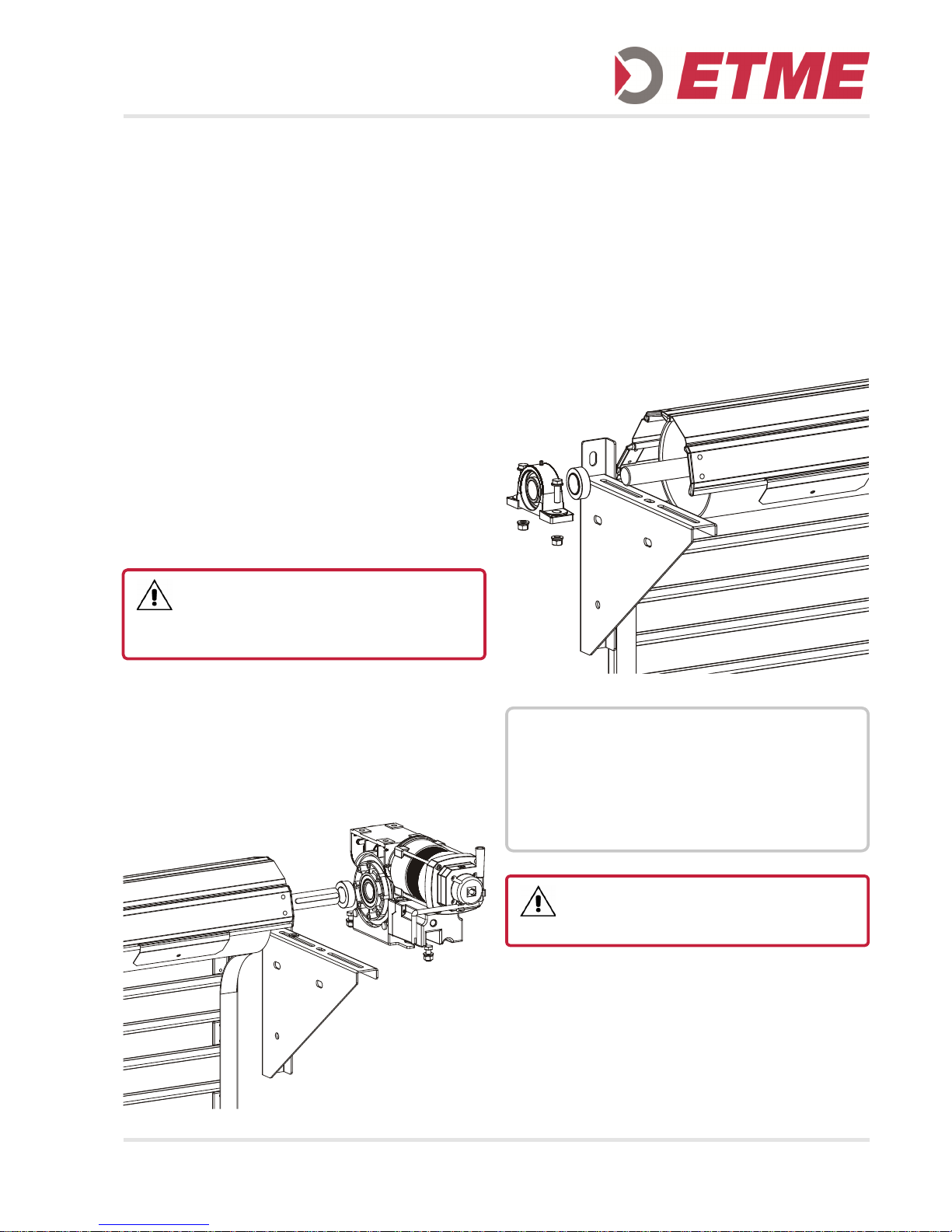
5.2 Mounting the Operator
Install the torque bracket
Insert the feather key into the shaft
The shaft end is greased before fitting the drive
When using collars, slide the collar onto the shaft
Secure the feather key against sliding
Connect the drive to the shaft
Attach the drive to the bracket
Slide the counter bearing onto the shaft
Attach the counter bearing to the bracket
The brackets must be mounted so that the shaft is
in the horizontal
The fixation against axial displacement of the shaft
is made on the opposite side at counter bearing, by
means of a screw or with collars on both sides
DANGER !
All components must be designed in relation to the
construction and the ground for the loads during tripping
of the safety catch device.
NOTICE !
To avoid damage to the operator and to the door, the
operator must be mounted on a bracket with a pendulum foot or a torque support bracket so that it is
vibration dampened.
When mounting the operator do not carry or pull at
the cable.
DANGER !
With a continuous shaft groove the feather key has to
be secured against moving.
6
6. ANTI-DROP SAFEGUARD
In accordance with the EN 12604 all RDA-operators
are equipped with an integrated locking device, which
works in both directions.
The locking device is entrained load-free and wearfree. If the drive unit fails, the locking device is automatically triggered. The load moved by the operator is
then smoothly brought to a standstill in the position
concerned.
The power transmission between the motor and the
door shaft is interrupted after the drive unit fails. The
operator must be replaced.
The anti-drop safeguard device is distinguished by the
following features:
Protection against worm shaft and worm gear failu-
re
Independent of the rotational speed
Independent of the direction of rotation
Can be mounted in any position
Unsusceptible to vibrations
Maintenance-free
Self-controlling
Excellent damping properties when device is trigge-
red
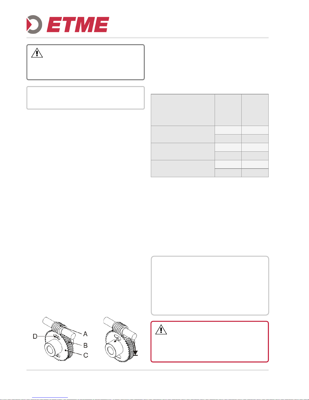
6.1 Function
In case of exceeding wear the teeth of the brass worm
wheel (B) may collapse and allow the wheel to turn
underneath the steel worm shaft (A). The pilot wheel
(C) remains unaffected, due to the relative rotation of
the two wheels a set of hardened lock-bolts (D) are
released and will immediately and permanently block
the gearbox.
7. INITIAL OPERATION
Power-operated doors shall be audited at least annually by a trained person, before first use and as required (with written proof).
The operator of the door system shall be trained after
initial operation.
Before installation, ensure that the direction of rotation
of the gear motor is correct, and all protective devices
are active.
CAUTION !
For operators with weights greater than 20 kg additional
aids shall be used, such as hooks or ropes for securing
and lifting. On the drives corresponding eyes are provided.
INFORMATION !
The relevant instructions for the door must be observed
when fitting the operator to the door.
Nebenstehende Maximalwerte dürfen auch
bei frequenzgeregeltem Betrieb nicht
überschritten werden
The values in this table may not be ex-
ceeded even in frequency controlled
operation
max. Betriebs-
drehzahl
max. Operating
Speed
max. zul.
Drehmoment
max. Torque
TOR-FV 5/083
100 min-1 200 Nm
200 min-1 100 Nm
TOR-FV 7/119
95 min-1 750 Nm
210 min-1 300 Nm
TOR-FV 6/111
30 min-1 1.554 Nm
120 min-1 1.118 Nm
NOTICE !
To avoid damage to the drive, the following points must
be observed:
The types of cable and their diameters must be sel-
ected according to current regulations.
The nominal currents and the type of connection
must correspond to those on the motor type plate.
The drive details must agree with the connected
loads.
DANGER !
Danger of fatal electric shock!
Before commencing cabling works, you MUST disconnect the drive system from the main supply. Ensure
that the electricity supply remains disconnected throughout the cabling works.
 Loading...