

ETM Purple User Manual
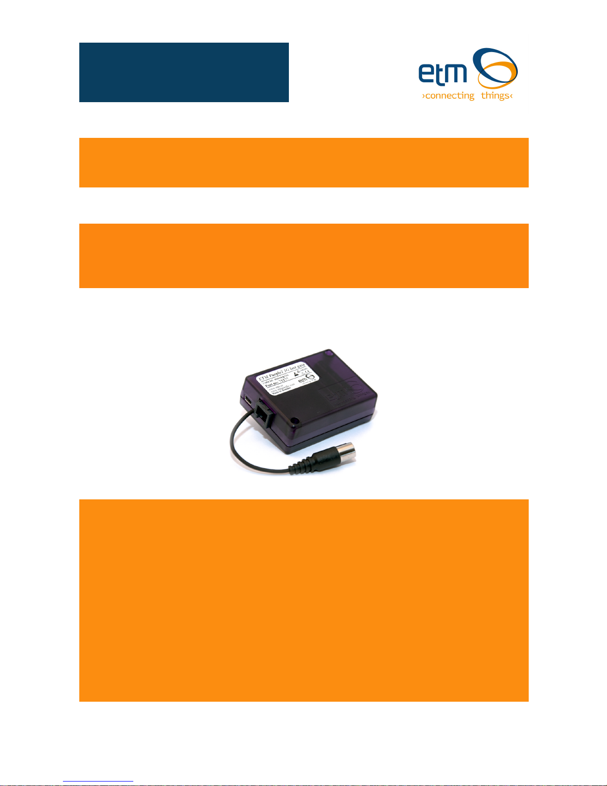
Intelligent Tri-Mode Terminal – ETM Purple
Features:
◩ Intelligent Tri-Mode Terminal, AT mode, ET Mode, JET Mode
◩ SMS, IP or CSD operation and/or configuration options
◩ Small form factor, to fit under meter covers or other enclosures with size constraints
◩ 2G (GSM/GPRS) Connectivity
◩ 3G (HSPA/UMTS) Connectivity
◩ 4G (LTE) Connectivity
◩ Combined or separate RS232 Serial & Power Connectors
◩ High speed USB
◩ RS422 and RS485 functionality
◩ Signal strength LED indicator
◩ 5 - 35V power input. 7 - 35V for last Gasp variants
◩ FME M antenna connector
ETM Purple user guide. 1802-20170003 R07
ETM-Purple User Guide

Contents
Contents ............................................................................................................................................ 2!
Revision History ................................................................................................................................. 3!
Introduction ........................................................................................................................................ 3!
Nomenclature ................................................................................................................................. 3!
Overview ........................................................................................................................................ 3!
Applications .................................................................................................................................... 3!
Tri-Mode Operation ........................................................................................................................ 4!
Physical Dimensions ......................................................................................................................... 5!
Separate Power RJ12 & Serial 10 pin Boxhead Connector .............................................................. 5!
Combined Power & Serial RJ45 Connector ...................................................................................... 6!
USB Communications Port ................................................................................................................ 6!
Antenna ............................................................................................................................................. 6!
SIM Card ........................................................................................................................................... 6!
SIM!Pin!......................................................................................................................................................!7!
Indicator Lights .................................................................................................................................. 7!
LED Behaviour - Normal Start Sequence ...................................................................................... 7!
Green LEDs ................................................................................................................................... 8!
Orange LEDs ................................................................................................................................. 8!
Installation ....................................................................................................................................... 10!
Initial Start-up & Configuration ......................................................................................................... 10!
Typical Startup Sequence ............................................................................................................ 10!
ET Mode/Configuration .................................................................................................................... 11!
Putting the Unit into ESC Mode ................................................................................................... 11!
ET Command Table ..................................................................................................................... 12!
Last Gasp Mode Operation ............................................................................................................. 14!
AT Mode Operation ......................................................................................................................... 15!
Common useful AT commands for basic operation include: ........................................................ 15!
SMS Specific Commands ............................................................................................................ 16!
AT Commands for Incoming Circuit Switch Data Calls ................................................................ 16!
JET Mode Operation ....................................................................................................................... 16!
JET Command table .................................................................................................................... 16!
JET!Configuration!change!respon ses !.......................................................................................................!18!
Installing the configuration tool in Windows 7. ............................................................................. 19!
Local!configuration!.................................................................................................................................!25!

Page 3 of 36 For Support Contact +46 25 28 75
or sales@etm.se
1802-20170003 07 ETM Purple user guide.docx
Revision History
Date
Revision
Editor
Description
2016-05-01
201605RV01
Patrick Paffard
First released version
2016-05-13
201605PRV02
Carl Håkansson
Added signal strength picture,
Added LED behaviour from Main code
2017-02-13
R03
Christian Leierer
Added Last Gasp information
2017-02-22
R04
Christian Leierer
Change parameters in tables
2017-06-13
R05
Carl Håkansson
Added config tool information
2017-08-04
R06
Carl Håkansson
Changed Nomenclature
2017-08-04
R07
Carl Håkansson
Changed part numbers
Introduction
Nomenclature
The ETM Purple variants incorporate the Cinterion BGS2, BGS5, EHS5, EHS6 or ELS61 module
and are intended for worldwide use (network and regulatory approvals permitting).
Terminal Nomenclature/History
Description
Part
number
Module
Installed
ETM Purple 2G, RJ12, Boxhead
71271
BGS2-E
ETM Purple 2G, RJ12, Boxhead, USB
71272
BGS5-E
ETM Purple 2G/3G Penta Band, RJ45, USB
71280
EHS6
ETM Purple 2G/3G Penta Band, RJ12, Box head, USB, Last Gasp
71284
EHS6
ETM Purple 2G/3G/4G, E-band, RJ45, USB
71423
ELS61-E
ETM Purple 2G/3G/4G, RJ12, Boxhead, USB, Last Gasp
71426
ELS61-E
ETM Purple 3G/4G US-Band, RJ45, USB
71355
ELS61-US
ETM Purple 3G/4G US-Band, RJ12, Boxhead, USB, Last Gasp
71356
ELS61-US
ETM Purple 3G/4G AUS-Band, RJ45, USB
71357
ELS61-AUS
Overview
The ETM Purple range of products, are intelligent industrial terminals designed for M2M (Machine
to Machine) communications. With 2G/3G & 4G connectivity, intelligent Tri-Mode operation and
small form factor they provide the ideal communications solution for electrical metering or other
applications utilising serial communications.
Applications
Typical applications include:
◩ RS232, RS422/485 or USB communications interface for electrical meters and data
concentrators
◩ Serial communications interface for other devices such as PLC’s, Irrigation controls, Security
and/or access systems, data loggers
◩ As a device for sending SMS alarms notifications based on AT commands from a connected
PLC, PC or Server

Page 4 of 36 For Support Contact +46 25 28 75
or sales@etm.se
1802-20170003 07 ETM Purple user guide.docx
Tri-Mode Operation
The unit can be operated in a number of ways to achieve different functional outcomes, depending
on the requirements of the device to which the unit is connected, and/or the interaction with any
back-end/server. The ETM Purple can support CSD or IP connections and SMS configuration or
status queries.
The following is a simplified block schematic to assist in understanding the operational capabilities
of the unit.
Mode/Command
Structure
Purpose
Interface Method
ET Commands
The external processor is used to control
the start sequence of the modem and
make default operational settings. It is also
used to configure "Last Gasp" functionality
(if applicable) and other features.
ET commands sent to serial
port if in ESC mode
SMS of a subset of ET
commands sent to the units
phone number (note SIM needs
to have SMS activated)
AT Mode
Depending on the setting made above the
unit can be operated as a basic 2G/3G/4G
modem using AT commands to drive the
unit
AT commands sent to the serial
or USB port
JET Mode
Provides intelligent operational functions
such as;
- TCP tunnel
- CSD tunnel
- TCP Server
- Serial to TCP Server
- Status Logging > sending to server for
monitoring (by others)
JET commands sent to the
serial port, or by SMS or by
TCP
Note that there may be a charge associated with the provision of JET code, and that it is possible
for customers to use the modem and to load their own Java™ code for a specific application. ETM
will not provide un-compiled JET code for use by others, it is the customers responsibility to
develop their own code using the resources available for the BGS5, EHS5, EHS6 or ELS61
module.
External Processor
ET Commands
Java Engine
JET Mode
EHS5/6 Wireless Module
AT Commands
ETM Purple Tri-Mode Intelligent
RS232 Serial
ET Mode
AT Mode
JET Mode
USB
AT Mode
(Modem Can be
powered by USB)
TM
Page 5 of 36 For Support Contact +46 25 28 75
or sales@etm.se
1802-20170003 07 ETM Purple user guide.docx
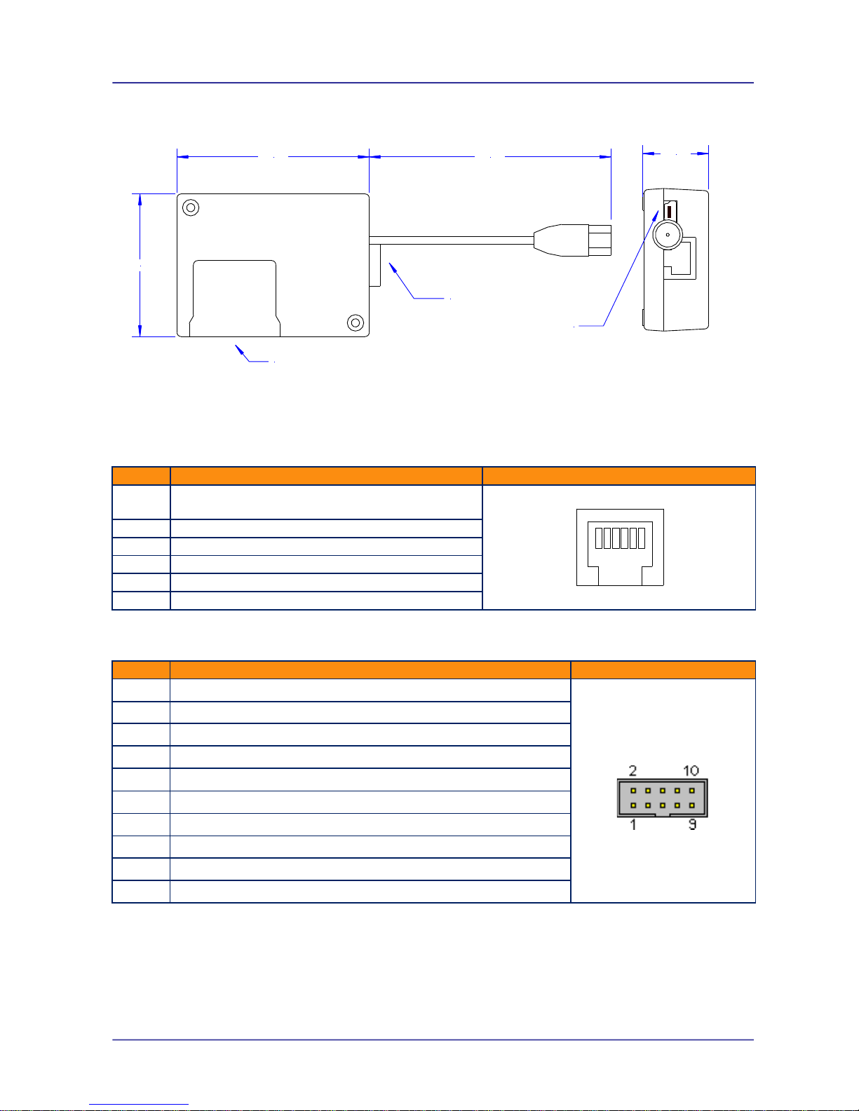
Physical Dimensions
Separate Power RJ12 & Serial 10 pin Boxhead Connector
Some models of ETM Purple utilises a 6-pin RJ12 connector for power, pin allocations are shown
below.
Pin
Function
Looking at Modem Socket
1
Power Supply (+5 to +35VDC) (+7 to 35VDC
for Last Gasp)
2
Not Used
3
Not Used
4
Not Used
5
Not Used
6
GND
Some models of ETM Purple utilises a 10-pin box head connector for communication, pin
allocations are shown below.
Pin
Function
Looking at Modem Socket
1
DCD Out
2
DSR Out
3
RXD Out
4
RTS In
5
TXD In
6
CTS Out
7
DTR In
8
RING Out
9
GND
10
Not Used
70.0
52.0
24.0
110
Approx.
SIM Cover
RJ45 Serial & Power Connector
Mini-USB Connector
123456
Page 6 of 36 For Support Contact +46 25 28 75
or sales@etm.se
1802-20170003 07 ETM Purple user guide.docx
Combined Power & Serial RJ45 Connector
Some models of the ETM Purple utilises a single RJ45 combined power and serial connector, pin
allocations are shown below.
Pin
Function
Looking at Modem Socket
1
Power Supply (+5 To 35VDC, 400mA @ 12VDC)
(+7 To 35VDC for Last Gasp)
2
DCD
3
DTR
4
GND
5
RX
6
TX 7 CTS
8
RTS
USB Communications Port
Mini-USB port for communications directly to the EHS6 module within the modem, drivers for
Windows need to be installed on the PC to allow access to this port.
The modem can be powered from the USB assuming the USB can deliver a voltage in the range of
+5 to 35VDC(+7V to 35V Last Gasp), if not a separate power supply via the RJ45 connector is
required.
Note: The NES DCN3000 data concentrator can be set to 12VDC output USB power.
AT commands and responses are available via the USB port.
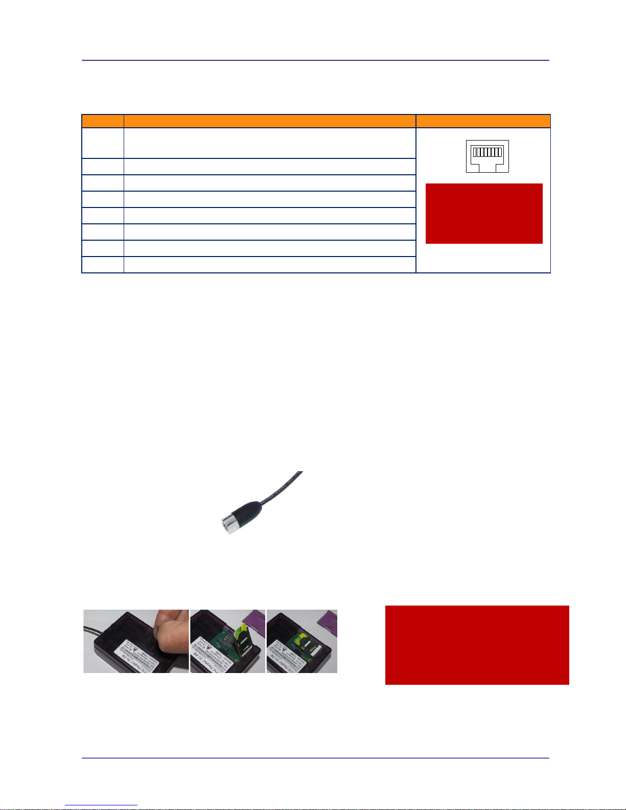
Antenna
The ETM Purple has a standard FME M antenna Plug on the end of an approximately 110mm
cable.
FME M Antenna Connector
SIM Card
The SIM card connector is located on the underside of the ETM Purple Terminal. The unit supports
both 3V or 1.8V SIMs. Any SIM card used needs to be correctly provisioned for the services and
network upon which it is intended to be used.
If the terminal is intended to be used for remote access to a device a terminating data number for
Circuit Switch Data (CSD) will need to be provisioned by the network operator, this number will
usually differ from any voice/SMS number. Other key configuration settings are;
◩ Telstra NextG® SIMs when used for CSD require 2620 bearer capability
Caution
Take care to ensure that only
the correct connectors are
used or mechanical damage
to the pins may result.
Caution
Always disconnect power supply before
inserting or removing SIM Card.
Care should be taken in inserting and
removing the SIM card so as not to
damage the SIM holder or cover.
12345678
Page 7 of 36 For Support Contact +46 25 28 75
or sales@etm.se
1802-20170003 07 ETM Purple user guide.docx
SIM Pin
If the SIM used has a PIN either;
• The unit can be configured to enter the SIM pin, refer applicable section of this manual
OR
• The SIM PIN should be deactivated, insert the SIM in a mobile phone and deactivate then
transfer the SIM into the ETM Purple unit.
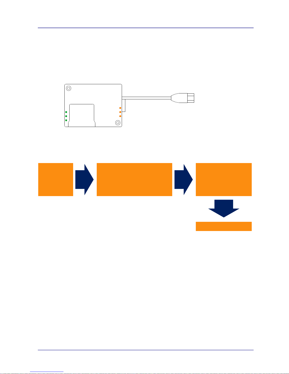
Indicator Lights
Looking at underside (SIM access side) of unit.
LED Behaviour - Normal Start Sequence
LED 1
LED 2
LED 3
LED 1
LED 2
LED 3
Green!LED1:!ON!
Green!LED2:!ON!
Green!LED3:!ON!
Green!
LEDs!
remain!
ON!
Orange!LED1:!ON!
(Indicating!that!Module!has!been!found)!
Orange!LED2:!ON!
(Indicating!that!Module!has!been!powered-up!OK)!
Orange!LED3:!ON!
(Indicating!that!SIM!card!has!been!found)!
All!LEDs!
turn!OFF!
Orange!LED1:!Flashing!!4times!
Orange!LED2:!Flashing!!4times!
Orange!LED3:!Flashing!!4times!
All!LEDs!turn!
OFF!
Then!See!LED!Behaviour!Below!

Page 8 of 36 For Support Contact +46 25 28 75
or sales@etm.se
1802-20170003 07 ETM Purple user guide.docx
Green LEDs
Green LED 1
Function
Slow Flash 500ms On / 500ms Off
Searching for mobile network
Double Flash 3s Off / 100ms ON / 100ms
OFF / 100 ms ON
Active 2G network connection
Triple Flash 3s OFF / 100ms ON / 100ms
OFF / 100 ms ON / 100ms OFF / 100ms
ON
Active 3G network connection
Four time Flash 3s OFF / 100ms ON /
100ms OFF / 100 ms ON / 100ms OFF /
100ms ON / 100ms OFF / 100 ms ON
Active 4G network connection
Green LED 2
Function
ON
Internet Service Provider connection (Active PDP
context and IP address)
OFF
No Internet Service Provider connection
Green LED 3
Function
Rapid Flash
Sending Data
ON
Receiving data from host (turn off after 2 seconds)
OFF
No data transmission occurring
Note: All LED will flash at boot up
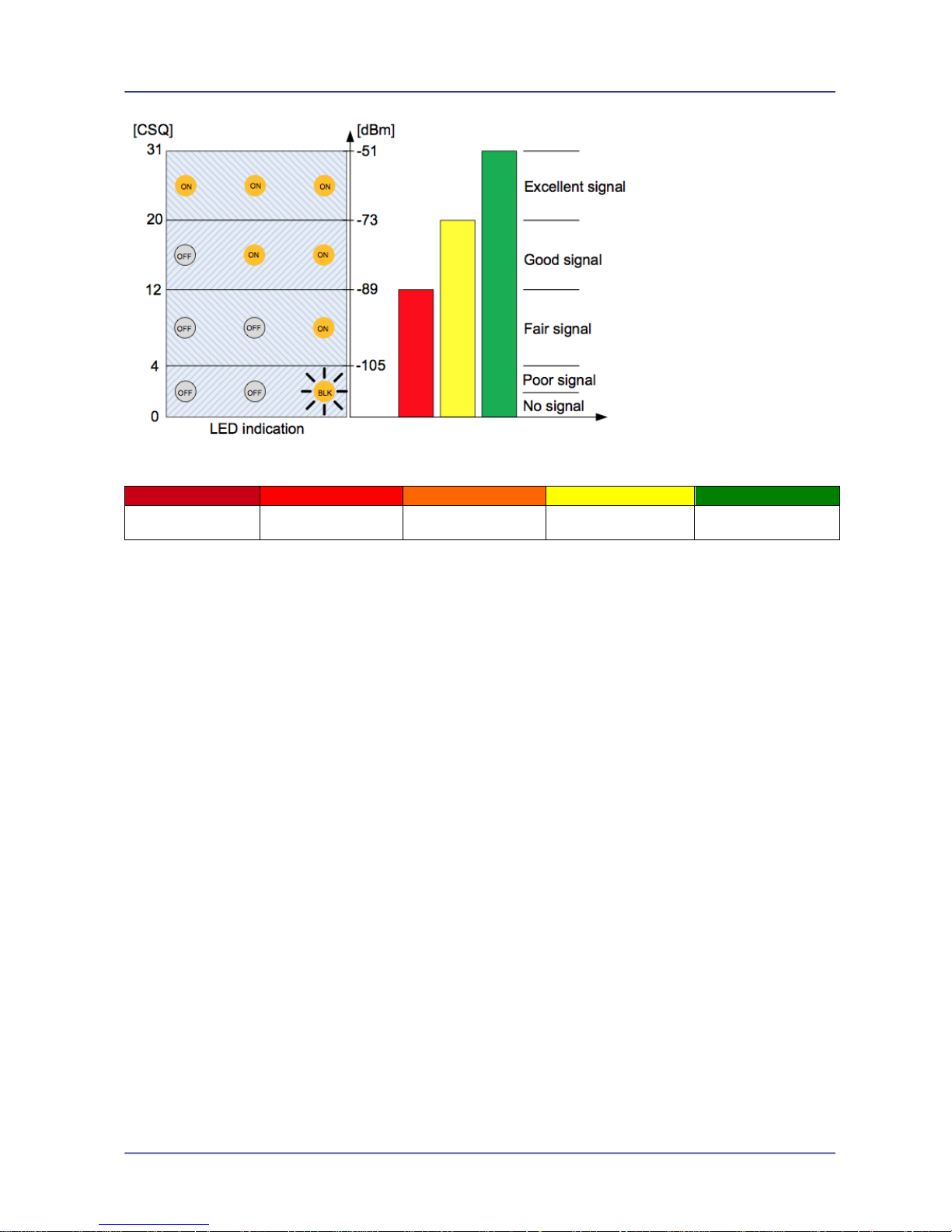
Orange LEDs
Orange LED 1
Function
Flashing
RSSI < -105 dBm or no SIM detected
ON
RSSI ≥ -105 dBm (Poor signal)
OFF
Not registered to mobile network ≥
Orange LED 2
Function
Flashing
No SIM detected
ON
RSSI ≥ -89 dBm (Fair signal)
OFF
RSSI < -89 dBm or Not registered to mobile network
Orange LED 3
Function
Flashing
No SIM detected
ON
RSSI ≥ -73dBm (Good signal)
OFF
RSSI < -73dBm or Not registered to mobile network
Page 9 of 36 For Support Contact +46 25 28 75
or sales@etm.se
1802-20170003 07 ETM Purple user guide.docx
-110 dBm
(no signal)
<-100 dBm
(poor signal)
-100 to -86 dBm
(fair signal)
-85 to -70 dBm
(good signal)
> -70 dBm
(excellent signal)
Signal strength levels.

Page 10 of 36 For Support Contact +46 25 28 75
or sales@etm.se
1802-20170003 07 ETM Purple user guide.docx
Installation
1. Connect a suitable serial interface to the modems RJ45 port or 10 pin box header depending
on model, see previous section for pinout details.
2. Fit a suitable antenna to the unit’s FME antenna lead.
3. Install a SIM card enabled for the services you intend to use. If the terminal is intended to be
used for Circuit Switch Data (CSD) a SIM with a terminating data number will need to be
provisioned by the network operator, this number will usually differ from any voice/SMS
number. Note that for Telstra you will need to request;
2620 bearer capability (Telstra NextG™ Sims)
4. Connect the power supply. (The unit accepts a broad range of voltages from +5 to +35VDC)
5. Refer to related sections of this manual for information on configuring the unit for the intended
mode of operation.
Initial Start-up & Configuration
The unit may be delivered in the following states depending on customer request, note that
additional costs may apply for certain functionality.
As delivered
State
Description
Start-Up
Standard – no
JET Code
Basic modem that may be
controlled by AT
commands from devices
such as a PC, electrical
meter or PLC
When the units power is connected and the
start-up sequence completed (approximately 2030 seconds) the serial and USB ports will
become available at the set baud rate for AT
commands
With JET Code
When JET code is
installed in the unit custom
functionality become
available
When power is connected and the start-up
sequence completed (approximately 20-30
seconds) the serial and USB ports will become
available at the set baud rate for AT commands.
Note that dependant on the JET code and actual
state the serial and/or USB ports may not be
accessible as they may be busy.
Depending on the configuration settings
associated with the JET code the JET code may
auto run or be manually started
Typical Startup Sequence
AT commands may now be sent to the unit.
Page 11 of 36 For Support Contact +46 25 28 75
or sales@etm.se
1802-20170003 07 ETM Purple user guide.docx
ET Mode/Configuration
ET Mode runs in the background irrespective of whether the unit is being used as a basic AT
modem controlled via AT commands from a connected device, or the JET functionality is being
used. ET mode enables configuration of the unit to run in a specific way, controls the Last Gasp
functionality (if applicable) and allows for some SMS based diagnostic queries.
ET commands can be sent to the unit via the serial port (RJ45 or box head) when the unit is in
ESC mode, a subset of the commands may also be sent by SMS to reconfigure the unit or query
the unit's status.
All commands must start with “ET” and end with Carriage Return(<CR> / ASCII 13).
The response will be: “Message Body” + “OK”
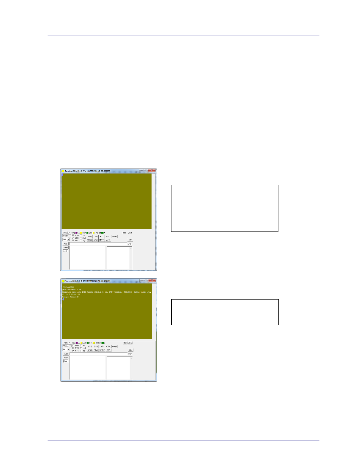
Putting the Unit into ESC Mode
To enter ESC mode and configure the ET functions the unit must be started while holding the ESC
key down in an active terminal window. The example below uses ETM's Term42 program and valid
terminal program will suffice.
1. Open and Setup a suitable Terminal Program
2. Power up Unit while holding down ESC key
You are now in ESC mode and ET configuration commands and queries can be sent to the unit.
Prior to starting the unit
Open a terminal program and
ensure the correct serial port is
open, the baud rate is 115200 and
the cursor is flashing in the terminal
window
Make sure you hold the ESC key on
until the unit confirms "Escape
Pressed!"
 Loading...