


UMTS/GSM/GPRS Terminal – ETM9140-1
GSM/GPRS Terminal – ETM9120-1
Features:
◩ 3G (HSPA+/UMTS) Connectivity – ETM9140-1 only
◩ 2G (GSM/GPRS) Connectivity
◩ Standard RS232 9DF serial port
◩ 5v to 35v power input on RJ12 connector
◩ 7 x I/O’s on RJ45 connector
◩ FME M antenna connector
◩ Sleep Mode for reduced power consumption
◩ User configurable via configuration tool
ETM9120 9140 Configuration Tool Userguide201406RV001
Configuration Tool Userguide

Page 2 of 46 For Support Contact +61-2-9956-7377
Or support@etmpacific.com.au
ETM9120 9140 Configuration Tool Userguide201406RV001
Contents
Contents ............................................................................................................................................ 2
Document .......................................................................................................................................... 4
History ........................................................................................................................................... 4
Relevant Documents ..................................................................................................................... 4
Abbreviation .................................................................................................................................. 4
Introduction ....................................................................................................................................... 5
Overview. ...................................................................................................................................... 5
Nomenclature ................................................................................................................................ 5
Using the Configuration tool .............................................................................................................. 5
Installation ..................................................................................................................................... 5
Initial Start-up and Programming ................................................................................................... 6
Saving, reading and writing configuration files .............................................................................. 7
File (Menu Option) ......................................................................................................................... 7
Alarm / Message Tab ........................................................................................................................ 8
SMS phone numbers and user ID ................................................................................................. 8
Latest Incoming SMS .................................................................................................................... 8
Unit ID added to messages ........................................................................................................... 8
Use incoming security filter ........................................................................................................... 9
Maximum number of SMSs per day allowed to be sent ................................................................ 9
Alarm Messages ............................................................................................................................ 9
I/O Settings ..................................................................................................................................... 10
IO 1 & 2 ........................................................................................................................................... 10
Delay before alarm is activated ................................................................................................... 10
Alarm restore delay ..................................................................................................................... 11
ET-cmd ........................................................................................................................................ 11
SMS Alarm .................................................................................................................................. 11
UMTS/GPRS Alarm ..................................................................................................................... 11
UDP Server Selection ................................................................................................................. 11
IO 3,4,5,6,7 ..................................................................................................................................... 11
Analogue Alarm Input .................................................................................................................. 11
A/D Cal Param ............................................................................................................................ 12
Power In Tab ................................................................................................................................... 12
Power Source Monitor ................................................................................................................. 12
Delay before alarm is activated ................................................................................................... 12
Alarm restore delay ..................................................................................................................... 12
ET-cmd ........................................................................................................................................ 12
SMS Alarm .................................................................................................................................. 12
UMTS/GPRS Alarm ..................................................................................................................... 12
UDP Server Selection ................................................................................................................. 13
Settings Tab .................................................................................................................................... 14
UMTS/GPRS Module <--> MCU and MCU <--> Port .............................................................. 14
Flow Control ................................................................................................................................ 14
EEPROM Storage Area ............................................................................................................... 14
Instructions on Correctly Setting the Baud Rate ......................................................................... 14
SettingtheInternalModulesBaudRate.................................................................................................15
Normal/Typical Start Sequence ................................................................................................... 17
Internet Tab ..................................................................................................................................... 18
Remote server ............................................................................................................................. 18
Local Server ................................................................................................................................ 18
Use Protocol ................................................................................................................................ 18
Firewall ........................................................................................................................................ 18
Transparency .............................................................................................................................. 18
ISP Dial up Login ......................................................................................................................... 19

Page 3 of 46 For Support Contact +61-2-9956-7377
Or support@etmpacific.com.au
ETM9120 9140 Configuration Tool Userguide201406RV001
Connect to ISP or Server ............................................................................................................ 20
Data Transfer Tab ........................................................................................................................... 21
Setting the SWT Timers .............................................................................................................. 21
Functional Timing Description ..................................................................................................... 22
Heart Beat package ..................................................................................................................... 23
Ping Sending ............................................................................................................................... 23
Analogue Values ......................................................................................................................... 24
Server ............................................................................................................................................. 24
Terminal .......................................................................................................................................... 25
Entering command mode ............................................................................................................ 25
Send – commands ...................................................................................................................... 25
Set RTC ....................................................................................................................................... 25
Reprogram Using CSD ................................................................................................................ 25
Main Init .......................................................................................................................................... 26
Default Mode ............................................................................................................................... 26
Miscellaneous .............................................................................................................................. 26
Init AT-Command Table .............................................................................................................. 27
Low Power Sleep Mode (SWT5) ................................................................................................. 27
ConsiderationswhenusingLowPowerSleepMode..............................................................................27
Active profile: ............................................................................................................................... 29
Logging Tab .................................................................................................................................... 31
Data Logging ............................................................................................................................... 31
Pulse Counting Transition ........................................................................................................... 31
Channels to Log .......................................................................................................................... 31
Wakeup Timer 1 Settings (SWT1) ............................................................................................... 31
Logging slots available ................................................................................................................ 32
Logged Data ................................................................................................................................ 32
Hardware Description ..................................................................................................................... 33
Power Supply .............................................................................................................................. 33
RJ45 I/O Connector ..................................................................................................................... 33
I/O Connector pins ...................................................................................................................... 34
Serial (RS232) Port ......................................................................................................................... 34
Antenna ........................................................................................................................................... 34
SIM Card ......................................................................................................................................... 35
SIMPin.....................................................................................................................................................35
Indicator Lights ................................................................................................................................ 36
Low Power Mode (LPM) Example/Description ............................................................................... 37
Real time Clock and reference date ................................................................................................ 39
Reference Date Description ........................................................................................................ 39
Real Time Clock Description ....................................................................................................... 39
I/O 7 Toggling ................................................................................................................................. 40
Calibration of Analogue Inputs ........................................................................................................ 42
Equipment we need: .................................................................................................................... 42
Procedure: ................................................................................................................................... 42
Querying/Programming the Modem Using ET Commands ............................................................. 45

Page 4 of 46 For Support Contact +61-2-9956-7377
Or support@etmpacific.com.au
ETM9120 9140 Configuration Tool Userguide201406RV001
Document
History
Revision Date Issued By Description
V001 30th April 2014 Patrick Paffard First Issue
Relevant Documents
The documents listed below are useful for the understanding of this document.
Document ID/No. Title
2005-0001 57 ETM Modems ET Communication Spec
2003-0003 16 ETM Modems TCP UDP Port Configuration Spec
2005-0001 17 ETM Modems TCP UDP Protocol Spec
ETM9140 9120 Quick Start
Guide 201405RV01
ETM9120 9140 Quick Start Guide
IO Board Brochure
201405RV01
IO Board Brochure
Abbreviation
Abbreviation Used Description
EEPROM Electrical Erasable Program Read Only Memory
UART Universal Asynchrony Receive Transmit
CR Carriage Return
LF Line Feed
CT Configuration Tool
MCU Microcontroller
RTC Real Time Clock
RD Reference Date
BPS Bits per second
WIRELESS MODEM ETM9120-1 OR ETM9140-1
GSM/GPRS/UMTS Wireless

Page 5 of 46 For Support Contact +61-2-9956-7377
Or support@etmpacific.com.au
ETM9120 9140 Configuration Tool Userguide201406RV001
Introduction
This document describes the operation of two ETM modems and therefore within this document
both types of product are referred to with the generic term of ‘wireless modem’ and wherever there
is a distinction required between the two there a clearly identified header will be shown for each
type of product;
Overview.
The ETM9xxx-xxx range of products are industrial terminals designed for M2M (Machine to
Machine) communications. With 3G &/or 2G options they provide the ideal communication, alarm
or control platform for GSM, GPRS, UMTS or SMS applications.
Nomenclature
The ETM9120-1 variants incorporate the Cinterion TC63i engine and are intended for worldwide
use (network and regulatory approvals permitting).
The ETM9140-1 variants incorporate the Cinterion PH8-P and are intended for worldwide use
(network and regulatory approvals permitting).
Terminal Nomenclature/History
Model Comment Module Installed
ETM9120 Variants
ETM9120-1 First Release TC63i
ETM9140 Variants
ETM9140-1 First Release PH8-P
This document refers to GSM/GPRS by the generic term ‘wireless’ and so you should
remember that the ETM 9120-1 wireless modem cannot access UMTS/HSDPA services.
This document refers to GSM/GPRS/UMTS/HSDPA by the generic term ‘wireless’ and so you
should remember that the ETM 9140-1 wireless modem can access GSM/GPRS/UMTS
services.
The wireless modem is equipped with an EEPROM that is programmed with an application image
supporting the required operation and functions of the wireless modem.
The data configured within the EEPROM is for alarm messages, telephone numbers, port input
and output status, baud rate, id numbers and user passwords.
A configuration tool is used to read-write to the modem to program specific functionality, it is very
important to ensure the correct version of the tool is utilised when reading or writing to/from the
modem.
Using the Configuration tool
Installation
The Configuration Tool can be copied to any folder on a suitable PC’s hard drive. It consists of only
one file and does not need to be installed. Depending on your use of the tool there may (over a
period of time) be configuration files, with an etx extension, created and these files can be saved in
any location. The tool itself may create a single ini file which should be left in the same directory as
the configuration tool for continued easy operation of the tool.
Page 6 of 46 For Support Contact +61-2-9956-7377
Or support@etmpacific.com.au
ETM9120 9140 Configuration Tool Userguide201406RV001
The wireless modem should be connected to the PC with a standard 9 pin serial (pc to modem)
cable – the wireless modem is configured as a DCE (Data Communication Equipment). New PC’s
and particularly laptops may need to utilise a USB-Serial converter to provide a serial port.
Initial Start-up and Programming
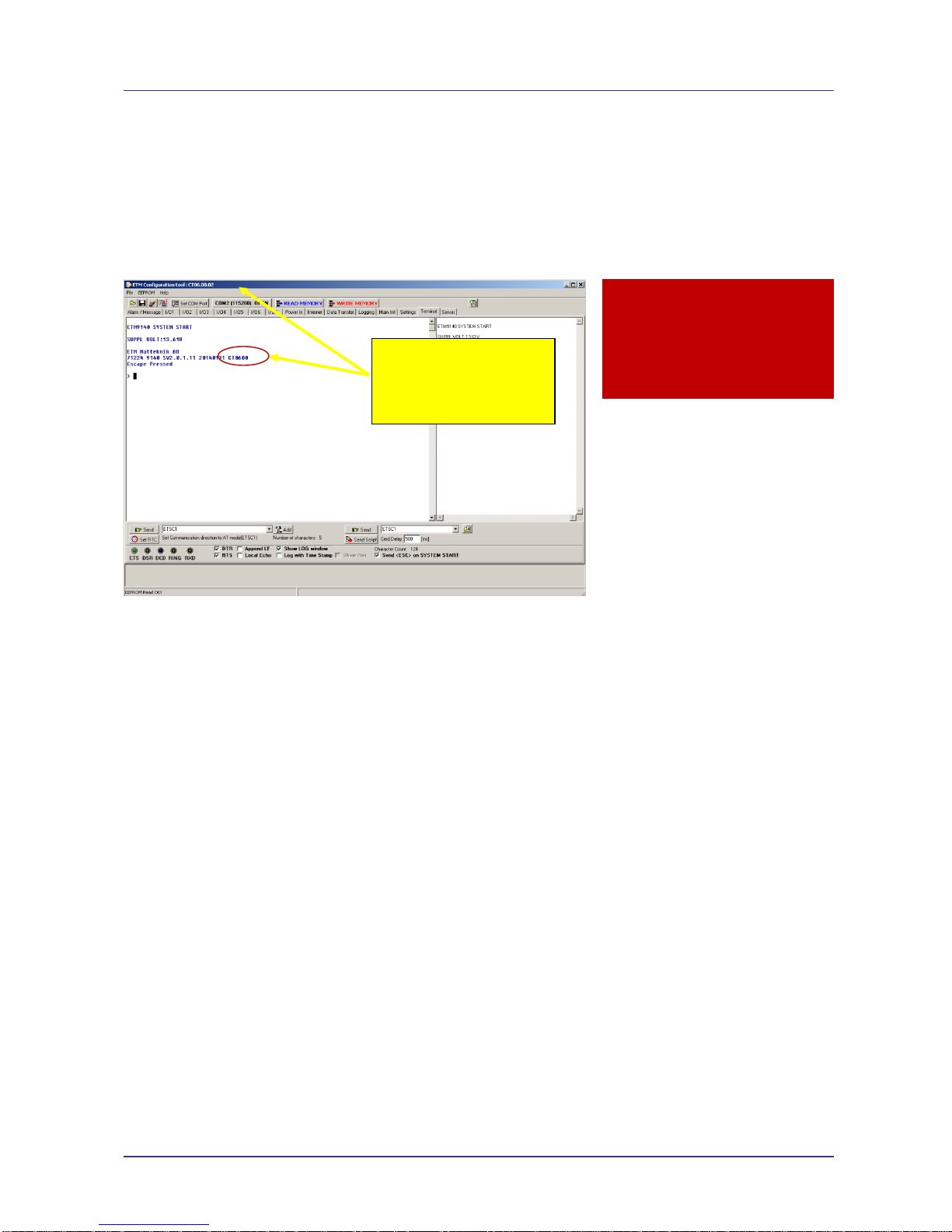
When the unit starts up and is connected to a terminal window and Escape is pressed (see below)
the version of the configuration tool will be shown as follows, check you have the correct
configuration tool for the unit – if you do not then contact ETM and request the appropriate version
or visit the support section of ETM’s website.
When you power up the wireless modem to do any configuration you MUST follow these steps if
you are unfamiliar with the operation of the Configuration Tool:
Start the configuration tool.
Chose the correct communications port ( using the Set COM Port button to select a port other
than the one chosen by the Configuration Tool ) – ensure the port is set for a baud rate of
115200 (it must be at this speed to be programmed in ESC mode).
Confirm that the port opens (the indicator MUST show ‘OPEN’ for your chosen port).
Click on the Terminal Tab.
Click into the black terminal window so that you see a flashing white cursor.
Power up the wireless modem - remember to plug the power into the correct socket, it is the
one next to the antenna lead, plugging the power connector into the I/O connector can
damage it, if this happens you may need to return the wireless modem for repair.
Immediately after powering up the modem press the ESC key on the keyboard, you should
only need to press it 3 or 4 times, after a short period you should see an ‘Escape Pressed’
message from the wireless modem – if you don’t and instead you see a ‘MS:^SYSSTART’
message then repeat the process again. Without the ‘Escape Pressed’ message being
displayed you CANNOT perform any configuration on the wireless modem (while it is possible
to use the Configuration Tool once the wireless modem has fully started up this may not be
possible if the wireless modem has not yet been fully configured).
NOTE: You can also check ‘Send <ESC> on SYSTEM START’ (the Configuration Tool to will
automatically send an ESC character when it sees the SYSTEM START message) in the
bottom right hand corner of the Configuration Tool (but this doesn’t work with some USB to
Serial adapters) – if you check this remember to uncheck it again when you restart the modem
after any programming changes, otherwise you may inadvertently leave the modem in
programming mode rather than run mode.
In this example the
appropriate
configuration tool is
CT0600
Caution
Do not try to program/configure a
unit with the wrong version of the
configuration tool.

Page 7 of 46 For Support Contact +61-2-9956-7377
Or support@etmpacific.com.au
ETM9120 9140 Configuration Tool Userguide201406RV001
You are now ready to use the configuration tool to make changes to the wireless modem.
Once you are familiar with the Configuration Tool you can shorten the procedure, if the
wireless modem is already live/working, by simply reading and writing the configuration without
restarting the wireless modem and pressing the ESC key. Note if any changes are made to the
modem you should power cycle or software reset (ET&SR) the modem to ensure that any new
mode of operation ( based on your configuration changes ) comes into effect. If you make no
changes, only reading the configuration, you do not need to restart the modem.
Settings can be saved to a file on your PC. If you need to configure another ETM9XXX-XXX
with the same settings this file can be loaded into the configuration tool and written to any
additional units that require the same settings.
Saving, reading and writing configuration files
File (Menu Option)
Select “File – Open” to open an existing configuration file.
Select “File – Save” to save a configuration file after you have read an existing configuration
from a device or when you have manually entered a configuration.
The configuration tool’s current settings can be written to the wireless modem by selecting
“WRITE MEMORY” – this is the button with the RED text.
Note: You cannot perform a write operation if you have not opened an existing configuration
file or performed a read operation.
To read the current settings of the wireless modem select “READ MEMORY” – this is the
button with the BLUE text.
“ComPort <Open> or <Closed>” can be used to control whether or not the communications
port is opened (You must have the communications port open to connect in any way to the
wireless modem).
The Port Open/Close feature allows you to leave the configuration tool open but not connected to
the serial port in case you need to use another communications application such as
HyperTerminal
.
The selected baud rate for the COM port is displayed in brackets when the port is opened.
Note: If the unit is busy a read or write may fail and a popup will inform you of the error, this is
usually because the unit is in normal/operational mode. You can retry the read or write but if it
continues to fails then put the unit into programming or ESC mode (see above).
Caution
Take care not to over-write a previously
configured unit with a default or other
incorrect configuration
We suggest reading back after making any
changes to confirm they have been
correctl
y
entered
Page 8 of 46 For Support Contact +61-2-9956-7377
Or support@etmpacific.com.au
ETM9120 9140 Configuration Tool Userguide201406RV001
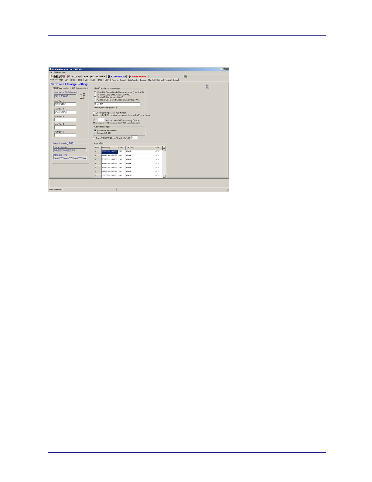
Alarm / Message Tab
The unit can send messages based on inputs to up to 5 mobile users.
SMS phone numbers and user ID
SMS Central is taken from the SIM-card and cannot be changed.
Number 1 – 5 lists the recipients of the alarm messages, i.e. +6141xyyyzzz
Note: It is our recommendation that you use the full international number in any entry.
Latest Incoming SMS
“Phone Number” shows the last number to send a valid message
“Date and Time” shows when the last valid message was received
Note: You can use these two entries to determine if there is a problem sending SMSs to the
wireless modem…. If you don’t see your SMS displayed it may be because your SMS is not
being delivered or because of an SMS formatting issue.
SMS formatting issues will affect you if you use a phone to send an SMS that has extra
characters inserted. As an example one type of phone will insert a variable line of dashes at
the top and bottom of an SMS and the wireless modem cannot then determine where, within
the SMS, the real content starts and so the SMS is rejected.
To diagnose whether or not the SMS has formatting issue you can send a test message from
your phone to another type of phone and see if there are extra characters OR call your
distributor and they may be able to give you a test number to send to and they could then let
you know whether the content and format of your messages is acceptable.
Unit ID added to messages
If you select “Use SIM Phone Book (Phone number 1) as User ID” the ID of the unit will be
whatever number is configured in that slot.
Note: This does not change the number from which any SMS is sent – it simply identifies the
device in the text area of any data sent.
If you select “Use SIM Card ID as User ID” the units ID will be the ID of the SIM.
See note above about the ID

Page 9 of 46 For Support Contact +61-2-9956-7377
Or support@etmpacific.com.au
ETM9120 9140 Configuration Tool Userguide201406RV001
If you want to enter a textual ID then enter it into the text box and uncheck the two checkboxes
above
You have forty (40) characters available and we suggest that you use the shortest practical ID
possible as there are only 160 characters available in an SMS and if you use 40 characters for
the ID this leaves only 120 characters for the content of the SMS which may limit the
information that can be sent.
When entering a specific ID you should not use punctuation characters – to guarantee that you
don’t affect the field positioning of any data being sent by the 9900 you should never use a
comma in the Device ID. If you have a comma in the Device ID you will effectively add a new
field to any data sent as the data is delimited with commas by default.
Use incoming security filter
You may restrict the users that can access the unit, users sending SMSs to the 9900 to control
configurable options or to return current statuses by selecting “Use incoming SMS security
filter”
Maximum number of SMSs per day allowed to be sent
To prevent a large number of SMSs being sent due to an invalid configuration or an unstable
input/system state you may limit the maximum SMSs sent in a single 24 hour period. This 24
hour period starts at the time the wireless modem is powered and is not based on any specific
time.
See the Delay
and Alarm Restore Delay description (within the individual I/Os) for other ways
to limit invalid sending.
If the wireless modem exceeds the maximum allowed SMSs in a single 24 hour period then
any alert that is triggered will still generate a message to the serial port (and will send a TCP
or UDP alert if configured) but no SMSs will be sent until the current 24 hour period expires.
There is no indication available of when the current 24 hour period expires.
Alarm Messages
Append Alarm status allows you to chose whether or not to add the status (High or Low) to the
alert message – by default you would normally enable this.
Append Unit ID allows you to choose whether or not to add the Unit Id to the alert message.
Page 10 of 46 For Support Contact +61-2-9956-7377
Or support@etmpacific.com.au
ETM9120 9140 Configuration Tool Userguide201406RV001
I/O Settings
7 x I/O’s configurable as digital, analogue or pulse are available on the RJ45 connector, pin
allocations are as shown below.
Pin Function Looking at Modem Socket
1 Configurable as:
◩ Digital Input: LL<0.5V, HL>2.5V, Max Input 50VDC
◩ Digital Output: LL0V, HL3V,0.1mA
◩ Pulse Input: LL<0.5V, HL>2.5V, Max Input 50VDC
2 Configurable as:
◩ Digital Input: LL<0.5V, HL>2.5V, Max Input 50VDC
◩ Digital Output: LL0V, HL3V,0.1mA
◩ Pulse Input (I/O8): LL<0.5V, HL>2.5V, Max Input 50VDC
3 Configurable as:
◩ Digital Input: LL<0.5V, HL>2.5V, Max Input 50VDC
◩ Digital Output: LL0V, HL3V,0.1mA
◩ Pulse Input (I/O9): LL<0.5V, HL>2.5V, Max Input 50VDC
◩ Analogue Input: 0-2.5VDC, Max Input 50VDC
4 Configurable as:
◩ Digital Input: LL<0.5V, HL>2.5V, Max Input 50VDC
◩ Digital Output: LL0V, HL3V,0.1mA
◩ Analogue Input: 0-2.5VDC, Max Input 50VDC
5 Configurable as:
◩ Digital Input: LL<0.5V, HL>2.5V, Max Input 50VDC
◩ Digital Output: LL0V, HL3V,0.1mA
◩ Analogue Input: 0-2.5VDC, Max Input 50VDC
6 Configurable as:
◩ Digital Input: LL<0.5V, HL>2.5V, Max Input 50VDC
◩ Digital Output: LL0V, HL3V,0.1mA
◩ Analogue Input: 0-2.5VDC, Max Input 50VDC
7 Configurable as:
◩ Digital Input: LL<0.5V, HL>2.5V, Max Input 50VDC
◩ Digital Output: LL0V, HL3V,0.1mA
◩ Analogue Input: 0-2.5VDC, Max Input 50VDC
IO7 can also be used as a „toggled“ output in combination with the ETM IO board
to provide switched sensor power supply – contact ETM for more details
8 GND
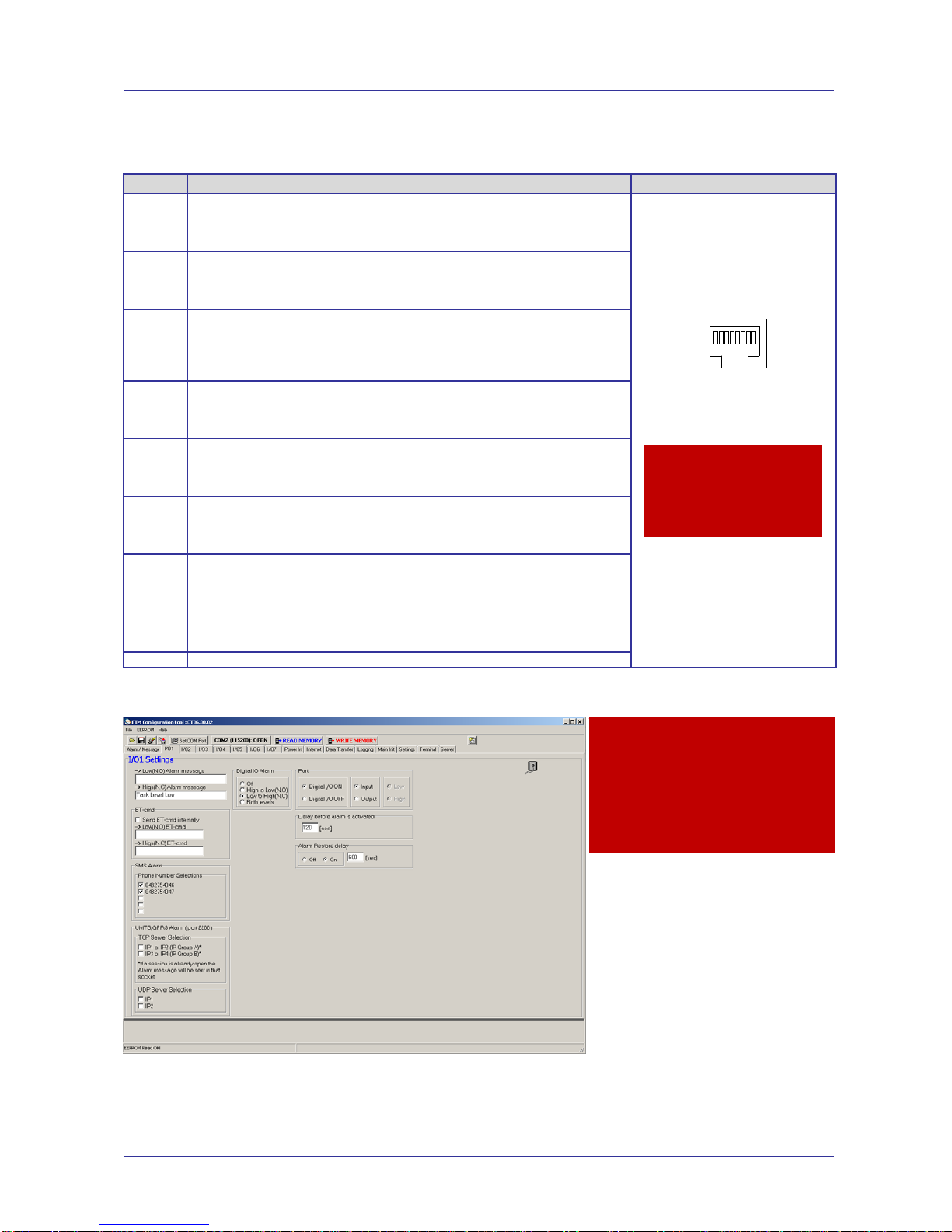
IO 1 & 2
Delay before alarm is activated
Is recommended to reduce the incidence of multiple SMS being sent in the event of
chattering/bouncing contacts
Caution
Take care to ensure that only
the correct connectors are
used or mechanical damage
to the pins may result.
12345678
Caution
SMS Alarm - Never tick a
blank number as this will
cause the modem to try to
repeatedly send an alarm to a
non-existent number
Page 11 of 46 For Support Contact +61-2-9956-7377
Or support@etmpacific.com.au
ETM9120 9140 Configuration Tool Userguide201406RV001
Alarm restore delay
Stops additional alarm messages occurring within X (in this case 600) seconds of original
event
ET-cmd
Allows for the internal sending of an ET command which could be used to change a timer or
turn on/off an output as the result of an alarm trigger on an input
SMS Alarm
Is used to indicate which, if any, phone numbers to use for sending SMS alarms related to this
input.
Never tick a blank number as this will cause the modem to try to repeatedly send an alarm to a
non-existent number
UMTS/GPRS Alarm
Allows for the sending of any alarm via TCP to server address and port nominated in the
Internet Tab
UDP Server Selection
Allows for the sending of alarms via UDP
In the Alarm / Message Tab a limit can be set on the number of SMS sent in every 24 hour period,
see previous page.
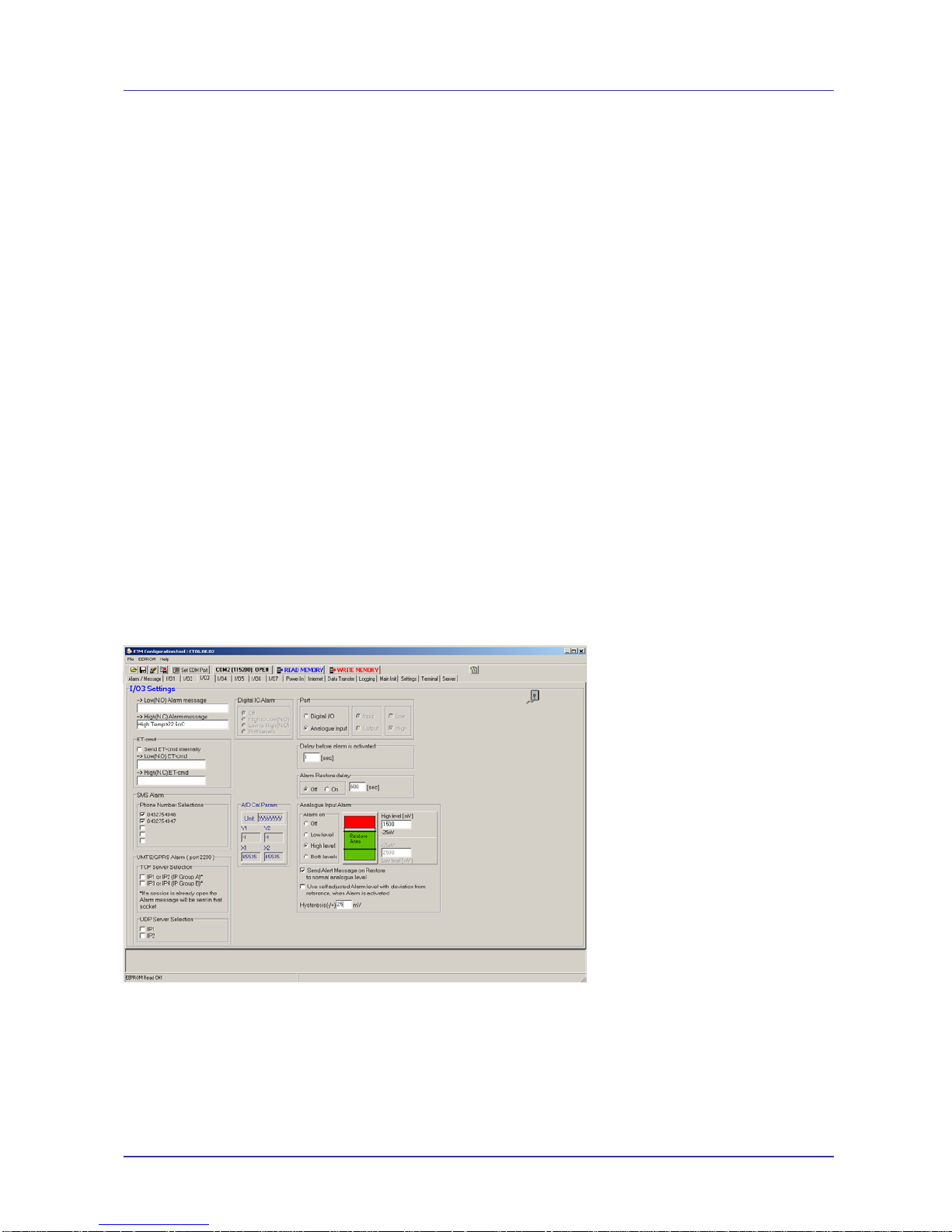
IO 3,4,5,6,7
These IOs can be set to Analogue as well as digital,
Analogue Alarm Input
Allows for high level, low level or both with hysteresis. Do not use the “Use self adjusted Alarm
level with deviation from reference, when alarm is activated” option without consulting ETM.
Hysteresis can be set, this is useful in eliminating nuisance alarms resulting from analogue
values fluctuating above and below the alarm setpoint causing multiple alarms to be sent.

Page 12 of 46 For Support Contact +61-2-9956-7377
Or support@etmpacific.com.au
ETM9120 9140 Configuration Tool Userguide201406RV001
A/D Cal Param
Shows the current calibration/scaling parameters for the input, refer section on calibration for
more information
IO7 can be used to toggle when logging occurs as a signal to switch power supply to a sensor,
refer logging section for more details
Power In Tab
The unit can send an alarm when the units supply voltage level has fallen below a specific level.
This can be used as a warning for backup battery, solar or mains power failure applications.
Power Source Monitor
Is typically used for internal battery versions and as such is not applicable to most applications
and should be ignored.
Delay before alarm is activated
It is recommended that this is always used for battery alarm applications to ensure nuisance
alarms are not generated.
Alarm restore delay
We do not recommend using this feature for most battery/mains power alarm applications.
ET-cmd
Allows for the internal sending of an ET command which could be used to change a timer or
turn on/off an output as the result of a low voltage alarm
SMS Alarm
Is used to indicate which, if any, phone numbers to use for sending SMS alarms related to this
input.
Never tick a blank number as this will cause the modem to try to repeatedly send an alarm to a
non-existent number
UMTS/GPRS Alarm
Allows for the sending of any alarm via TCP to server address and port nominated in the
Internet Tab

Page 13 of 46 For Support Contact +61-2-9956-7377
Or support@etmpacific.com.au
ETM9120 9140 Configuration Tool Userguide201406RV001
UDP Server Selection
Allows for the sending of alarms via UDP
Page 14 of 46 For Support Contact +61-2-9956-7377
Or support@etmpacific.com.au
ETM9120 9140 Configuration Tool Userguide201406RV001
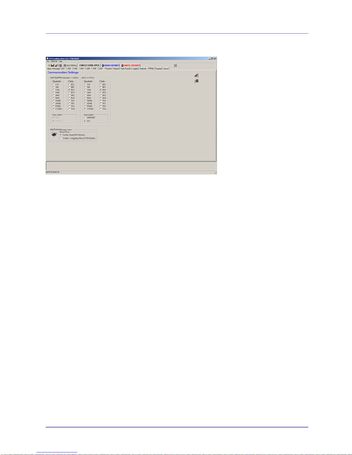
Settings Tab
UMTS/GPRS Module <--> MCU and MCU <--> Port
UMTS/GPRS Module <--> MCU should match MCU <--> Port.
MCU <--> Port sets the serial port on the wireless modem and should be adjusted to suit your
device connected to the port.
Flow Control
Currently, only CTS Flow Control is supported
EEPROM Storage Area
Currently, this should be configured to ‘Config Area’
Instructions on Correctly Setting the Baud Rate
The baud rate of the ETM9xxx-xxx modem needs to be set as above with both the
UMTS/GPRS<>Module and MCU<>Port Settings being the same plus the internal engine/module
(TC63i/PH8-P) must be set to the same baud rate using AT+IPR command.

Page 15 of 46 For Support Contact +61-2-9956-7377
Or support@etmpacific.com.au
ETM9120 9140 Configuration Tool Userguide201406RV001
Setting the Internal Modules Baud Rate
1. Change to AT Mode using the ETSC1 command, this can be sent using the drop down box on
the bottom left or by typing into the terminal window
2. Set the baud rate using the at+ipr=xxxx command, where xxxx is the desired baud rate, note
this speed setting will need to match the settings under the “Settings”tab.
Common ET
commands can be
found and sent from
here

Page 16 of 46 For Support Contact +61-2-9956-7377
Or support@etmpacific.com.au
ETM9120 9140 Configuration Tool Userguide201406RV001
3. Send --- to return to command mode and continue programming the unit.
If the baud rate set in the settings tab does not match the modules baud rate then an error
similar to that shown below on start-up will occur, when the unit is started in run mode.

Page 17 of 46 For Support Contact +61-2-9956-7377
Or support@etmpacific.com.au
ETM9120 9140 Configuration Tool Userguide201406RV001
To solve the above problem wait until the ETM9910 SYSTEM START message appears and
press the ESC key to put the unit into escape mode for programming, if successful the screen
should look as follows.
Now follow the procedure on the previous page to set the baud rate correctly, make sure it
matches the baud rates set in the “Settings” tab.
Normal/Typical Start Sequence
Upon re-starting the modem, with the port set to the correct speed, you should see the following
typical start-up sequence, this sequence may vary depending actual unit settings.
Press ESC at this
point, or have “Send
<ESC> on System
Start” box ticked

Page 18 of 46 For Support Contact +61-2-9956-7377
Or support@etmpacific.com.au
ETM9120 9140 Configuration Tool Userguide201406RV001
Internet Tab
This section has settings which controls how the unit communicates over the internet with a server.
Remote server
IP Address 1 and 2 are a pair of addresses that can be used on the Internet Transfer page.
The wireless modem will switch between the two addresses in the group if one address cannot
be contacted.
IP Address 3 and 4 are a second pair of addresses that can be used on the Internet Transfer
page. The wireless modem will switch between the two addresses in the group if one address
cannot be contacted.
The port address is the port number on the remote server.
You will need to forward the chosen port(s) to a server behind your firewall.
Local Server
This sets the port number from which the unit sends its messages.
We recommend that port 2040 be used
Use Protocol
This lets you select UDP or TCP protocol as the default protocol.
Firewall
If you turn on the firewall only IP-packets coming from the IP-addresses specified in Group A
and Group B will be responded to.
Transparency
Delay before data send [*25ms]
Enable this option if you don’t always have a specific termination character or chractcters,
such as a carriage return, to trigger the send.
Delay before data send should be unchecked if you are using Termination Character(s)
Port Buffer Size
This is limited in total to 512 bytes
You can send up to 512 bytes in one packet – there is no buffer beyond the single 512 bytes
available
Termination Character

Page 19 of 46 For Support Contact +61-2-9956-7377
Or support@etmpacific.com.au
ETM9120 9140 Configuration Tool Userguide201406RV001
If you are sure that there is always a defined character on the end of a line to be sent enter the
HEX representation of the ASCII value for that character and select ‘Use Termination’.
You should always start entering the termination character (string) from the left hand side of
the entry area and any entries that are not used should have FF entered.
If your termination is less than 8 characters then enter 00 directly after the entered termination.
As an example if you are searching for HEX 0A (the Linefeed character) then you would enter;
0A 00 FF FF FF FF FF FF
‘Use Termination’ should be unchecked if it is not used
A good place to look for the correct HEX representation of ASCII values is
http://www.asciitable.com/
ISP Dial up Login
APN sets the Access Point Name to use with the GPRS connection.
In this string;
+cgdcont=1,"ip","internet"
… you would only change “internet” to “internet.netcom.no” or select the right APN from the
drop down menu.
You can overwrite any of the available APNs if your APN does not exist.
If you want to create your own list of APNs you need only create a text file with the appropriate
APNs and then select the ‘file open’ button to the right of the topmost APN dropdown list to
load your chosen list.
UMTS/GPRS Module Dial up Code’ should be;
d*99***1#
…. that is – d star 99 star star star 1 hash (or pound)

Page 20 of 46 For Support Contact +61-2-9956-7377
Or support@etmpacific.com.au
ETM9120 9140 Configuration Tool Userguide201406RV001
Password
Is the appropriate password for the service being utilised.
Connect to ISP or Server
Connect to ISP at start-up
When the unit powers up it can automatically connect to the ISP.
Connect to Server at start-up
When the unit powers and automatically connects to the ISP the unit will establish a socket to
IP1 or IP2.
Use of this feature, ‘Connect to Server at startup’, will cause some aspects of the
capabilities on the ‘Internet Data Transfer’ tab to be unavailable. Use of this feature would
result in a permanent connection being maintained to the nominated server.
Max Reconnect Period
This is the maximum time, duration, a reconnect will be attempted before it is considered a
failure. We recommend a value of 10 in this entry
Max Reconnect Trials
This is the maximum amount of times (5 recommended) a reconnect will be attempted before
the wireless modem is restarted in an effort to connect to the carrier.
If the reconnect trials have been reached, and the module is attempting to connect to a server,
the wireless modem will disconnect from the ISP and try to establish a new connection. If the
wireless modem is trying to connect to an ISP and the limit has been reached, the wireless
modem will software reset and then try to establish a new ISP connection.
Note in relation to Reconnect Period and Trials
If the LPM timer expires before the reconnect period/trials then the wireless modem will not
reset and will instead go into sleep mode (LPM). When the wireless modem comes out of
sleep mode (LPM) the previous failures will be ignored and the counters will start again.
This allows the wireless modem to continue to perform as a data logger in a situation where
there is no signal.
Disconnect Socket if inactive
You can use this to disconnect from your Server if you don’t send data for a specified period
(to save costs for example).
After disconnection from the Server you can still send SMSs or UDP packages to the unit, to
cause it to reconnect if required, the unit must be powered or connected to an ISP (for UDP).
This feature is not useful if sleep mode functionality is being used.
RTC SYNC Server
IP address of server to be used
Use Memory Stored RTC at Startup
Use the RTC stored within the unit at startup

Page 21 of 46 For Support Contact +61-2-9956-7377
Or support@etmpacific.com.au
ETM9120 9140 Configuration Tool Userguide201406RV001
Data Transfer Tab
This section has settings that control how the unit sends data over the internet to a server.
The Internet Data Transfer tab is laid out in a vertical pattern with each vertical segment relating to
a particular timer (SWT<x>) that controls the sending of certain data types.
The three timers that relate to the sending of data are;
1. SWT2 – This timer sends the archived/logged data. The sending port will be 2150.
2. SWT3 – This timer sends the current values as configured. The sending port will be 2800.
3. SWT4 – This timer sends the current values as configured. The sending port will be 2880.
The data types are defined in the separate document, ‘ETM Modems TCP UDP Protocol spec’.
Setting the SWT Timers
Setting the SWT timers is done by clicking on the Terminal tab and then clicking on the terminal
window, so that a flashing cursor is displayed.
To set an SWT timer you send the following command;
ETSWT=Y,00:00,XX
….. where Y is the timer designation and XX is the timer period in minutes.
Command
Eg SWT1 Every minute ETSWT=1,00:00,1
Or every ten minutes ETSWT=1,00:00,10
Start at midday and then every 30 minutes after that ETSWT=1,12:00,30
* (Synchronized to Real Time Clock) must be checked for this to work
* If you use the Synchronized to Real Time Clock functionality you need to enable it first in the
wireless modem using the configuration tool, write the configuration to the wireless modem and
power cycle the wireless modem. Then you should return to configuring the unit.
One thing to note about using Synchronized to Real Time Clock is that if the software clock in
the wireless modem has a time that is past the time entered then the wireless modem will not
trigger the timer until the following day.
You cannot modify the SWT timer minute values in the various tabs of the configuration tool – this
task must be completed in the method described above.

Page 22 of 46 For Support Contact +61-2-9956-7377
Or support@etmpacific.com.au
ETM9120 9140 Configuration Tool Userguide201406RV001
Functional Timing Description
The presented configuration delivers the following solution (the intervals may not be representative
of a valid setup but they are acceptable for this description):
STW2 - Causes the archived/logged data in any selected inputs to be sent every 10 minutes,
see the logging
tab for which specific inputs are being sent. With the logging of the inputs
taking place every minute a total of 7 data sets will be sent each time the timer expires. The
data will be delivered to the IP address and port nominated in the IP1/IP2 group.
STW3 - Causes the current device information, signal levels / supply voltages, to be sent
every 60 minutes. The data will be delivered to the IP address and port nominated in the
IP3/IP4 group.
STW4 - Causes the current location information, a GPS must be plugged into the wireless
modem and the serial port set correctly in the Settings
tab, to be sent every 5 minutes. The
data will be delivered to the IP address and port nominated in the IP1/IP2 group.
Using this configuration the unit is logging and sending the signal levels plus supply voltage (on the
wireless modem) every sixty minutes to a server on 103.103.103.103 port 1003 (104.104.104.104
port 1004 if IP3 is not available) as well as allowing the server to interrogate the wireless modem
(using the #8 command capability – this capability needs to be written by the client in whatever
programming language that allows suitable TCP/UDP access).
The client is also logging seven logged inputs, see the logging
tab for which specific inputs are
being sent, every minute and sending the results every ten minutes to 101.101.101.101 port 1001
(102.102.102.102 port 1002 if IP1 is not available)
And finally the client is tracking the unit by GPS and this data is being sent every five minutes to
101.101.101.101 port 1001 (102.102.102.102 port 1002 if IP1 is not available).
Open and send data (port xxxx)
Only SWT timers, 2 / 3 / 4, with this option checked will send data
Periodic timer Setting
You have two choices here, ‘Periodic’ or ‘Synchroised to Real Time Clock’ and both are very
different;
1. Periodic sending works on the configured interval so that if a value of 60 is entered a send
will occur every 60 minutes.
There is, however, no control of what actual time the sending starts so if you need a
sending to occur at a certain time you need to use ‘Synchronised to Real Time Clock’.
2. Synchronised to Real Time Clock starts a send at the nominated time and then ADDS the
‘Sending Period’ to that time so that the next send is performed at the time required.
There is one significant issue with this type of sending – if your device is powered off and
then powered on again at a later time the ‘Real Time Clock’, which is a software and not
hardware clock, will now be out of sync with the real time and so your chosen starting
times will no longer be accurate.
The wireless modem can have it’s ‘Real Time Clock’ and ‘Reference Date’ reset by either
connecting to serial port and sending the correct ET commands, the wireless modem does
not need to be put into command mode but it must also not be asleep, OR the next time
that the wireless modem connects by UDP or TCP the server can issue commands to
resynchronise the wireless modem ‘Real Time Clock’ and ‘Reference Date’

Page 23 of 46 For Support Contact +61-2-9956-7377
Or support@etmpacific.com.au
ETM9120 9140 Configuration Tool Userguide201406RV001
Heart Beat package
Note: This feature has the potential to cause you issues if your carrier does not support short
interval sending with minimal data content. Check your carriers terms of usage before you start to
use these features.
Note: Where there is ‘telstra’ in any part of the APN this feature is disabled, even though you can
configure it in the configuration tool,
Send Data every x [min]
Set the value in whole minutes for the interval between sends – the minimum recommended
interval 1 minute
SMS Sending
[#30] format, Unit ID
Sends an SMS formatted as “#30….” every X minutes to provide an indication that the unit is
still “alive”
UDP Sending
[#3] Unit ID (Port 2100)
This sends the Unit ID from port 2100
[#3] Unit ID (Port xxxx)
This sends the Unit ID from port xxxx
The port used (xxxx) is the same as the local port entered in the ‘Internet’ Tab.
[#4] Analogue Port status (Port 2050)
This sends the current Analogue Port status values from port 2050
#4,2,,4,000444,AI1.14,1462.75,mV,AI2.15,1498.16,mV,AI3.3,2499.38,mV,AI4.4,2499.38,mV,AI5.5,2499.38,mV,AI6.6,2499.38,mV,
AI7.7,2499.38,mV,SUPPL VOLT,13.50,V,VeR+,1369,mV,VeR-,0,mV,MCUT,1081,mV,Vcc/2,1514,mV
,
[#6] Digital Port status (Port 2051)
This sends the current Digital Port statuses from port 2051
#6,2,,4,000446,1:DI,1,2:DI,1,3:DI,1,4:DI,1,5:DI,1,6:DI,1,7:DI,1,8:DI,1,9:DI,1,
The advantages of sending this data by UDP is that transmission costs are reduced, using the
UDP (connectionless protocol) compared to TCP.
The disadvantages of sending this data by using UDP is that because UDP is a connectionless
protocol there is no guarantee that the data will be delivered. The wireless modem does not
implement any form of delivery success detection on top of UDP.
Ping Sending
Note: Where there is ‘telstra’ in any part of the APN this feature is disabled, even though you can
configure it in the configuration tool,
Ping Format needs to be checked for this feature to function.
No of Ping failures before ISP disconnect means that if an initial data send can be initiated
then a ‘ping failure’ is registered and after a configured amount of failures the ISP is
considered to be disconnected and the wireless modem will attempt to reconnect to the carrier
Use Local IP-Add when sending Ping is used to make the wireless modem ping itself in an
effort to maintain the ISP connection.

Page 24 of 46 For Support Contact +61-2-9956-7377
Or support@etmpacific.com.au
ETM9120 9140 Configuration Tool Userguide201406RV001
Analogue Values
Default (presented in mV)
Analogue values, sent by TCP, UDP or SMS are presented in mV, the range of each analogue
input is 0-2500mV
Scaled with calibrated values
Analogue values, sent by TCP, UDP or SMS are presented as calibrated/scaled values, refer
to section on calibration for more details
Server
It is possible to connect to the modem, for reprograming and or issuing commands, but the
following points are relevant for any implementation.
1. When using NAT, as many carriers do, you don’t have any available port mappings to access
the wireless modem from the Internet and so you need to confgure one of the SWT timers to
connect to your own fixed Internet address and port and then to use the;
#8 ET – Command Response
.... option which will allow your server code to communicate directly with the wireless modem
as though it were plugged into the serial port.
You have up to 30 seconds to send a command to the wireless modem (using #8) otherwise
the wireless modem will disconnect the socket.
One very important thing to note is that if you set a #8 option on any SWT timer you MUST
have a receiver on the configured Internet address able to connect to the wireless modem and
issue at least an ET command otherwise the wireless modem will continue to attempt to
connect indefinately or until the module goes into sleep mode (if configured)........ this could
result in a high data costs.
2. If you have a VPN or can directly access the IP address of the wireless modem then you can
open a socket to port 2055 on the wireless modem and any command that starts with ET will
be processed as an ET command and any other received data will be sent transparently to the
serial port.
3. There is no error checking on transmitted data so while you can use UDP to reduce costs you
would be better served by using TCP which has more reliability
4. While the wireless modem is in sleep mode or is disconnected from the network there is no
way to contact the wireless modem
5. You can send an SMS to the wireless modem to get it to reconnect to the network, if it is
disconnected, but you cannot wake the unit (if in sleep mode) up with an SMS

Page 25 of 46 For Support Contact +61-2-9956-7377
Or support@etmpacific.com.au
ETM9120 9140 Configuration Tool Userguide201406RV001
Terminal
In the terminal window you can see the output from the unit and type commands to the unit. Note :
Remember to place the cursor inside the window before you type any commands.
Entering command mode
Place the cursor inside the window and press “escape” (or have Send ESC on SYSTEM
START checked) to stop the start up sequence and put the unit into ESC mode. You may also
issue ET-commands when in normal operation mode but the unit might be busy and fail to
execute the command, wait and try again. Make sure to set baud rate to 115200 for the
escape sequence to work.
Send – commands
You can select a number of predefined commands by using the drop down menu. Not all
commands are listed here. Note that each command has a short description. For full details
refer to the ET Command list document.
The drop down on the left has predefined commands, the one on the right has commands
previously used, to make sending a command repeatedly, easier.
Set RTC
This button is used to set the Reference Date and Time, se ection on Real Time Clock and
Reference Date
Reprogram Using CSD
If your SIM has been provisioned for Circuit Switched Data, then it is possible to dial into the unit
from the terminal window and re-program the unit remotely.

Page 26 of 46 For Support Contact +61-2-9956-7377
Or support@etmpacific.com.au
ETM9120 9140 Configuration Tool Userguide201406RV001
Main Init
Default Mode
When the unit powers up it can start in 3 modes:
ET mode is standard operating mode
In AT mode the unit behaves like a standard GSM/UMTS wireless modem where the user
controls the internal module directly without using the MCU.
In GPS-capture mode data coming from a GPS connected to the serial interface is stored in
the unit. The last position can be requested via SMS and when used as alarm each message
can have the position appended.
Note: If you select #5 for either SWT3 or SWT4 (Data Transfer tab) you MUST configure the
unit to start in GPS mode othwerwise the GPS feed will be ignored.
When in GPS mode all normal ET mode functions are supported EXCEPT commands on the
serial port as it is dedicated to receiving GPS data – all ET commands continue to work on
UDP or TCP when in GPS mode.
Miscellaneous
Switch to ET-mode when CD is active
allows that the unit operates in ET command mode whenever a dial in connection is active.
This is useful for programming the unit over a dial up connection.
Accept incoming CSD when CD is active
Suspend active GPRS session (2G) when an incoming CSD call occurs, this feature does not
work for 3G/WCDMA– contact ETM should you wish to use this feature
Force Send Data when in Module Direct
Used for background sending of data collected by the unit when in AT mode – contact ETM
should you wish to use this feature
Force SW reset every 24 hours
Unit will be reset every 24 hours
SW Reset if Inactive x [min]

Page 27 of 46 For Support Contact +61-2-9956-7377
Or support@etmpacific.com.au
ETM9120 9140 Configuration Tool Userguide201406RV001
If the modem remains inactive for more than x minutes the unit will reset
Configuration ID No
An ID that can be used to further identify a unit configuration, may be used to identify standard
configurations for a particular application.
Init AT-Command Table
Here you may set various AT and/or ET commands that are executed at power up.
Low Power Sleep Mode (SWT5)
This is used when you wish to operate a unit in sleep mode to conserve power, in sleep mode the
units power consumption drops to 0.15 mA. The units digital and analogue alarms will function in
sleep mode however the delays before an alarm is sent are affected by the analogue alarm check
period, and the time for the unit to wake and register to the network – the interaction between
these timers need to be carefully considered.
Considerations when using Low Power Sleep Mode
If the unit operates from a battery and you need to conserve power it can be set to wake up every
‘x’ minutes, for ‘y’ minutes, to send data etc.
When the wireless modem wakes up it will scan the SWT timers and determine which timers
are ready to trigger a data send.
If an SWT timer is not ready to trigger a data send, and the wireless modem wakes up, then
any sending for that timer will be ignored.
What you should know about Low Power Mode;
During Low Power Mode operation there is no contact with the network and so SMSs
will be held in the carriers SMSC and so you cannot guarantee the order in which
SMSs will be delivered to the wireless modem..... this means that if you send an SMS
to configure an option and send a reset then there is no guarantee which will be
actioned first and as a reset can cause the wireless modem to restart without
consideration of any other activity on the wireless modem you might find that your
second (configuration) command ‘gets lost’ so you need to plan accordingly
During Low Power Mode operation a change on a configured I/O that would normally
cause an alert to occur will cause the unit to wake up, the IOs are scanned every “x”
minutes in Low Power Mode, and so there is no guarantee that a unit will stay in Low
Power Mode for as long as expected.
If an external device, processor or a simple switch, changes the state of Pin 2 on the
power connector then the wireless modem will come out of Low Power Mode.
You should configure sufficient awake time so that the wireless modem can complete
any tasks that you have set such as delivering #21 or #22 data or accepting commands
using a #8 connection.
You can change the Low Power Mode times using an SMS, direct connection to the
serial port or when connected to the wireless modem socket either directly or by #8.
The minimum awake time can only be changed via the configuration tool.
Use Low Power Mode
Check or uncheck this option to enable or disable LPM mode

Page 28 of 46 For Support Contact +61-2-9956-7377
Or support@etmpacific.com.au
ETM9120 9140 Configuration Tool Userguide201406RV001
Periodic Timer Setting
Refer to the description of Periodic versus Synchronizes to Real Time Clock in the ‘Internet
Data Transfer’ section for a description of the differences between these two timing methods
Min Awake Time
This setting is configured within this text entry box – you set the minimum period of time that
the wireless modem should stay awake for in whole minutes.
The wireless modem may be busy performing configured operations and so exceed the time
value entered here but once the configured interval has expired and the wireless modem has
been inactive for a short period it will automatically switch to LPM mode.
Our recommendation is that this value should never be less than 4 minutes.
Next wake-up time
This information is ‘display only’ and is only relevant if you are using Synchronizes to Real
Time Clock.
Displayed is the next time that the wireless modem will wake up if LPM is enabled.
This time value is changed using LPM and you should refer to the ‘Internet Data Transfer’
section for a description of this time value.
Sleeping Period (SWT5)
This information is ‘display only’ and is relevant if you are using Periodic or Synchronizes to
Real Time Clock
Displayed is the total time that the modem will sleep if LPM is enabled.
The LPM mode timer, SWT5, works in the following manner;
The ‘Sleeping Period’ defines the total interval that the wireless modem works with, when
determining when to wake up.
The ‘Min Awake Time’ defines the minimum interval that the wireless modem is awake for
within the ‘Sleeping Period’.
So to describe the capability we imagine that the ‘Sleeping Period’ is set for 60 minutes
and the ‘Min Awake Time’ is set for 10 minutes and that the wireless modem is turned on
for the first time at 00:00,
The wireless modem starts at 00:00, performs as expected (connects to the network) and
then after all configured sending takes place and the ‘Min Awake Time’ has expired the
wireless modem will switch to LPM mode very shortly after 00:10
The wireless modem wakes from LPM at 01:00 and performs the same steps as above –
once the wireless modem determines that the internal timer is at 01:10 it will switch to
LPM as soon as possible.
The wireless modem will continue to perform in this manner indefinately.
Analogue Alarm Check Period
If the wireless modem is in LPM then the scanning interval of the analogue inputs can be set
to every <x> minutes.

Page 29 of 46 For Support Contact +61-2-9956-7377
Or support@etmpacific.com.au
ETM9120 9140 Configuration Tool Userguide201406RV001
Reducing the scanning interval can provide power savings as the action of scanning an
Analogue input requires a small power burden when the Analogue inputs are powered up to
take a reading, in addition if IO7 is being used to switch sensor power then reducing the
frequency at which the sensor is turned on will save power.
DTR and I/O2 (99xx) Powerup toggling
Toggling the DTR pin on the RS232 connector or grounding pin 2 on the POWER connector
will wake the unit from sleep
Active profile:
The Active Profile allows you to control the way that the wireless modem responds to the terminal
in normal use.
Long Result Format (ETPSR)
Checked (default) provides Long format (text) responses. Unchecked will send short format
(numeric) responses
Response Info Print Out (ETP)
Checked (default) info response printed. Unchecked, info response not printed
SMS Response Msg (ETPM)
This sets whether or not the modem sends received SMSs to the serial port
Echo (ETE)
This sets whether the wireless modem echos commands
Options are;
ETE1 – Echo commands
ETE0 – Do not echo commands
Note: This has no affect when in AT Mode and you should set ATE1 or otherwise after the
wireless modem has fully initialised.
Result Print Out (ETPR)
Checked (default) result printed. Unchecked, result not printed
Effects of Active Profile Settings
If you uncheck all the options in the Active Profile you will not see any responses from the wireless
modem – including when the wireless modem is first turned on.
For normal AT mode operation you would have the following options checked;
This would result in the following output from the wireless modem:
ETM9900 SYSTEM START
10
SIM READY
Registered, roaming
Net Provider:"3TELSTRA"
Signal Quality:-85dBm(14)"Low"

Page 30 of 46 For Support Contact +61-2-9956-7377
Or support@etmpacific.com.au
ETM9120 9140 Configuration Tool Userguide201406RV001
Signal Quality:-85dBm(14)"Low"
Signal Quality:-85dBm(14)"Low"
SMS Message Service OK
SIM:SMS Central no:+61418706700
SUPPL VOLT:15.62V
The wireless modem would be ready to use once the ‘SUPPL VOLT:’ message was
received
For standard ET mode operation (as say an SMS alarm) you would have all options checked.

Page 31 of 46 For Support Contact +61-2-9956-7377
Or support@etmpacific.com.au
ETM9120 9140 Configuration Tool Userguide201406RV001
Logging Tab
A limited amount of data can be stored in memory during periods of network outages or if sleep
mode is used.
Data Logging
Off
On (Timed)
On (Timed/Event on IO1)
When an alarm event occurs on input 1 the unit takes a log
Pulse Counting Transition
High to Low
Counts a pulse on transition from open circuit (>2.5V) to closed circuit (<0.5V)
Low to High
Counts a pulse on transition from closed circuit (<0.5V) to open circuit (>2.5V)
Both (High to Low AND Low to High)
Counts transitions from high to low and low to high
Channels to Log
Select the channel to be logged and the type of logging required.
Wakeup Timer 1 Settings (SWT1)
Periodic
Periodic sending works on the configured interval so that if a value of 60 is entered a log will
occur every 60 minutes.
There is, however, no control of what actual time the logging starts so if you need logging to
occur at a certain time you need to use 'Synchronised to Real Time Clock'.
Synchronised to Real Time Clock
Starts at the nominated time and then ADDS the 'Period' to that time so that the next send is
performed at the time required.

Page 32 of 46 For Support Contact +61-2-9956-7377
Or support@etmpacific.com.au
ETM9120 9140 Configuration Tool Userguide201406RV001
The logging interval timer SWT1 needs to be set in the terminal window using the
ETSW=1,YY:YY,X command where; YY:YY is the nominated start time and X is the interval in
whole minutes.
Logging slots available
The amount of logging slots available is determined by how many inputs you log at any one time.
1 Input logged – 3412 slots …. @ 1 minute logging = 56 hours 52 minutes storage
2 Inputs logged – 2362 slots .. @ 1 minute logging = 39 hours 52 minutes storage
3 Inputs logged – 1806 slots .. @ 1 minute logging = 30 hours 6 minutes storage
4 Inputs logged – 1462 slots .. @ 1 minute logging = 24 hours 22 minutes
5 Inputs logged – 1228 slots .. @ 1 minute logging = 20 hours 28 minutes storage
6 Inputs logged – 1058 slots .. @ 1 minute logging = 17 hours 38 minutes storage
7 Inputs logged – 930 slots …. @ 1 minute logging = 15 hours 30 minutes storage
Logged Data
This area shows the data as it is retrieved from the wireless modem

Page 33 of 46 For Support Contact +61-2-9956-7377
Or support@etmpacific.com.au
ETM9120 9140 Configuration Tool Userguide201406RV001
Hardware Description
Power Supply
The ETM9xxx-xxx power connection is a 6 pin RJ12 connector, pin allocations are shown below.
Pin Function Looking at Modem Socket
1 Power Supply (+5 to +35VDC)
2 Not Used
3 Flash Download
4 DTR (can be used as wake-up pin)
5 Not Used
6 GND
RJ45 I/O Connector
7 x I/O’s configurable as digital, analogue or pulse are available on the RJ45 connector, pin
allocations are as shown below.
Pin Function Looking at Modem Socket
1 Configurable as:
◩ Digital Input: LL<0.5V, HL>2.5V, Max Input 50VDC
◩ Digital Output: LL0V, HL3V ,0.1mA
◩ Pulse Input: LL<0.5V, HL>2.5V, Max Input 50VDC
2 Configurable as:
◩ Digital Input: LL<0.5V, HL>2.5V, Max Input 50VDC
◩ Digital Output: LL0V, HL3V ,0.1mA
◩ Pulse Input (I/O8): LL <0.5V, HL>2.5V, Max Input 50VDC
3 Configurable as:
◩ Digital Input: LL<0.5V, HL>2.5V, Max Input 50VDC
◩ Digital Output: LL0V, HL3V ,0.1mA
◩ Pulse Input (I/O9): LL <0.5V, HL>2.5V, Max Input 50VDC
◩ Analogue Input: 0-2.5VDC, Max Input 50VDC
4 Configurable as:
◩ Digital Input: LL<0.5V, HL>2.5V, Max Input 50VDC
◩ Digital Output: LL0V, HL3V ,0.1mA
◩ Analogue Input: 0-2.5VDC, Max Input 50VDC
5 Configurable as:
◩ Digital Input: LL<0.5V, HL>2.5V, Max Input 50VDC
◩ Digital Output: LL0V, HL3V ,0.1mA
◩ Analogue Input: 0-2.5VDC, Max Input 50VDC
6 Configurable as:
◩ Digital Input: LL<0.5V, HL>2.5V, Max Input 50VDC
◩ Digital Output: LL0V, HL3V ,0.1mA
◩ Analogue Input: 0-2.5VDC, Max Input 50VDC
7 Configurable as:
◩ Digital Input: LL<0.5V, HL>2.5V, Max Input 50VDC
◩ Digital Output: LL0V, HL3V ,0.1mA
◩ Analogue Input: 0-2.5VDC, Max Input 50VDC
IO7 can also be used as a „toggled“ output in combination with
the ETM IO board to provide switched sensor power supply –
contact ETM for more details
8 GND
Caution
Take care to ensure that only
the correct connectors are
used or mechanical damage
to the pins may result.
123456
12345678

Page 34 of 46 For Support Contact +61-2-9956-7377
Or support@etmpacific.com.au
ETM9120 9140 Configuration Tool Userguide201406RV001
I/O Connector pins
Each I/O Connector pin is protected by a RC coupling that is displayed in the figure below.
To Micro
Controller
Vcc
R2
R1
C1
I/O
Connector
Pin
C2
R1 = 1 M, R2= 33 K C1 = 4,7nF C2 = 0,1uF
All pins have the same protecting circuit, whether they are used for digital or analogue signals, or
programmed as input or output.
Serial (RS232) Port
The RS232 Port is the primary interface for the application software and connection to external
devices. ET/AT commands are used to communicate with the terminal. The RS232 interface is
implemented as a 9-pin D-Sub socket with screw fittings.
Pin Function
1 DCD Out
2 RXD Out
3 TXD In
4 DTR In
5 GND
6 DSR Out
7 RTS In
8 CTS Out
9 RING Out
Antenna
The ETM9xxx-xxx Terminal has a standard FME M antenna Plug on the end of an approximately
110mm cable.
FME M Antenna Connector

Page 35 of 46 For Support Contact +61-2-9956-7377
Or support@etmpacific.com.au
ETM9120 9140 Configuration Tool Userguide201406RV001
SIM Card
The SIM card connector is located on the underside of the ETM9xxx-xxx Terminal. The unit
supports both 3V or 1.8V SIMs. Any SIM card used needs to be correctly provisioned for the
services and network upon which it is intended to be used.
If the terminal is intended to be used for remote access to a device a terminating data number for
Circuit Switch Data (CSD) will need to be provisioned by the network operator, this number will
usually differ from any voice/SMS number. Other key configuration settings are;
◩ Telstra NextG® SIMs when used for CSD require 2620 bearer capability
SIM Pin
If the SIM used has a PIN either;
The unit can be configured to enter the SIM pin, refer configuration tool section
OR
The SIM PIN should be deactivated, insert the SIM in a mobile phone and deactivate then
transfer the SIM into the ETM9xxx-xxx unit.
Caution
Always disconnect power supply before
inserting or removing SIM Card.
Care should be taken in inserting and
removing the SIM card so as not to
dama
g
e the SIM holder or cover.

Page 36 of 46 For Support Contact +61-2-9956-7377
Or support@etmpacific.com.au
ETM9120 9140 Configuration Tool Userguide201406RV001
Indicator Lights
Signal Strength Indication During Start-up
Signal Strength
Signal < 10 10 ≤ Signal < 15 15 ≤ Signal < 20 20 ≤ Signal < 25 25 ≤ Signal
Weak Low
Medium
High Strong
Blue LED
ON ON
OFF
OFF OFF
Yellow LED
OFF ON
ON
ON OFF
Green LED
OFF OFF
OFF
ON ON
Blue LED (UMTS) Function
Single Flash LED flashes when the ME is registered to the UMTS network and either
awake or in power saving state.
Double Flash Connected to an ISP
Off ME is not registered to the UMTS network.
YELLOW LED
(MCU)
Function
Flashing Communicating with the module
500ms On / 500ms
Off
Waiting for Answer from Module
On When connected to an ISP and a Socket is established.
GREEN LED
(GSM)
Function
500ms On / 500ms
Off
Flashes at 1Hz and 50% duty cycle when the ME is awake and not registered
to any network.
2s On / 2s Off Flashes at 0.25 Hz and appr. 50% duty cycle when the ME is in power saving
state and not registered to any network. When the ME is in power saving
state and not registered, the flashing frequency may be less than 0.25Hz and
the duty cycle may vary, for example between 45% and 55%. These
variations are due to transitions from awake state to power saving state
which may occur at the beginning of an LED flashing period (eg. at the
beginning of a 1Hz or 0.25Hz flashing period). In the worst case, the LED will
indicate a transition from awake to power saving after 4s.
Flashing LED flashes when the ME is registered to the GSM network and either awake
or in power saving state.
While the STATUS0 signal is active the STATUS1 signal is inactive.
Double Flashing Connected to an ISP
Off ME is not registered to the GSM network.
Blue
UMTS
YELLOW
MCU Status
Green
GSM
ETM9xxx-xxx Status LEDs

Page 37 of 46 For Support Contact +61-2-9956-7377
Or support@etmpacific.com.au
ETM9120 9140 Configuration Tool Userguide201406RV001
Low Power Mode (LPM) Example/Description
[Setup Information]
15:24:21.32 : ETM9140 SYSTEM START
15:24:27.49 : SUPPL VOLT:14.72V
15:24:28.57 : ETM Matteknik AB 71224 9140 SW2.0.1.15 20140218 CT0600 Escape Pressed >
15:24:31.19 : ETSWT? 1,PTL:1,1 2,PTL:2,2 3,PTL:2,2 4,PTL:5,5 5,PTL:10,10 OK
15:24:38.78 : et&sr
OK
SW RESET:Cmd
and Min Awake Time in Main Init Tab set to 4 Minutes
[First Run]
15:24:43.01 : ETM9140 SYSTEM START
15:24:49.19 : SUPPL VOLT:14.80V
15:24:56.02 : MS:^SYSSTART
15:25:04.04 : SIM READY
15:25:07.02 : Registered, home network
15:25:08.05 : Net Provider:"505 01",2
15:25:09.03 : Signal Quality:-97dBm(8)"Weak"
15:25:13.40 : SMS Message Service OK
15:25:14.18 : SIM:SMS Central no:+61418706700
15:25:17.23 : SUPPL VOLT:14.58V ETM9140:>
15:25:18.70 : Modem Init:at+cgdcont=1,"IP","telstra.internet"
15:25:19.32 : Init OK Connect:atd*99***1# ISP Connect
15:25:25.32 : PAP Login OK Waiting for IP-Context
15:25:28.67 : Local IP Address:10.102.65.178
15:25:29.26 : MSG:INTERNET CONNECT Connecting RIP:220.245.206.138:18000 LP:2800 MSG:SOCKET OPEN[!]
15:25:53.26 : MSG:SOCKET CLOSED
15:26:05.16 : Connecting RIP:220.245.206.138:18000 LP:2800 MSG:SOCKET OPEN[!]
15:26:26.26 : MSG:SOCKET CLOSED Connecting RIP:220.245.206.138:18000 LP:2150 MSG:SOCKET OPEN[!]
15:26:30.76 : MSG:SOCKET CLOSED
15:28:05.32 : Connecting RIP:220.245.206.138:18000 LP:2800
15:28:06.03 : MSG:SOCKET OPEN[!]
15:28:28.27 : MSG:SOCKET CLOSED Connecting RIP:220.245.206.138:18000 LP:2150 MSG:SOCKET OPEN[!]
15:28:33.28 : MSG:SOCKET CLOSED
15:28:50.80 : LPM:ON
15:34:11.32 : LPM:OFF SUPPL VOLT:14.97V
15:34:18.57 : MS:^SYSSTART
15:34:26.57 : SIM READY
15:34:29.58 : Registered, home network
15:34:30.60 : Net Provider:"505 01",2
15:34:31.58 : Signal Quality:-95dBm(9)"Weak"
15:34:35.97 : SMS Message Service OK
15:34:36.70 : SIM:SMS Central no:+61418706700
15:34:39.80 : SUPPL VOLT:14.50V ETM9140:>
15:34:40.99 : Modem Init:at+cgdcont=1,"IP","telstra.internet"
15:34:41.58 : Init OK Connect:atd*99***1# ISP Connect
TS:15:28:50.80 - LPM:ON (15:24:43.01 Start and 15:28:50.80 LPM ON = approx. 4 Minutes awake period)
TS:15:34:11.32 - LPM:OFF (15:28:50.80 LPM ON and 15:34:11.32 LPM OFF = approx. 6 Minutes)
... therefore we have a 10 minute sleeping period timer (SWT5) with a 4 minute period (set as Min Awake
Time, in the Main Init Tab) within the sleeping period where the modem is awake.
The wireless modem sleep mode functionality works on a sliding window and so the ‘sleeping period’ defines
the (approximate) maximum time that the wireless modem waits between sleep interrupts and the ‘Max
awake time’ is the (approximate) timeframe within that defined ‘sleeping period’ that the wireless modem can
send the data (be awake).
There is some variation possible within the wireless modem so that while you set a ‘Max awake time’ of 2
minutes it is possible that the unit will stay awake longer (up to 1 minute) because the wireless modem did
not finish all the required tasks within the allocated timeframe.
This will be more apparent the more you have chosen to send because each individual send will take a finite
amount of time and if, for example, you set an awake time that is too short for the sending of #21, #22, #5
and #4 data the wireless modem will wait for the next internal timer interrupt and if the ‘Max awake time’ has

Page 38 of 46 For Support Contact +61-2-9956-7377
Or support@etmpacific.com.au
ETM9120 9140 Configuration Tool Userguide201406RV001
expired then a final send may be undertaken and then the wireless modem would move immediately to
LPM:OFF – when you see this in the log you could assume that the wireless modem had performed the
required tasks incorrectly when it had in fact done the best that it could do based on the configuration.
So you need to remember that the ‘Max awake time’ is the time from when the wireless modem starts up
until all required tasks are completed and then the ‘sleeping period’ is the time from when the wireless
modem wakes up, goes to sleep again and then wakes up again. Therefore the ‘sleeping period’ includes the
‘Max awake time’ – so you should not expect that the ‘Max awake time’ is after the ‘sleeping period’.
One final thing…… in general operation we would not expect to see a ‘sleeping period’ of less than an hour
so if you test a ‘sleeping period’ of 5 minutes with a ‘Max awake time’ of 2 minutes , you may not get a valid
representation of the typical operation of the modem in its final intended configuration. Most clients have
‘sleeping period’ set to 1440 and ‘Max awake time’ set to 4 or 6 minutes as they use LPM to save as much
power as they can.

Page 39 of 46 For Support Contact +61-2-9956-7377
Or support@etmpacific.com.au
ETM9120 9140 Configuration Tool Userguide201406RV001
Real time Clock and reference date
Reference Date Description
The wireless modem uses the reference date as a base to time and date any subsequent alarms
or data that is processed.
Real Time Clock Description
The wireless modem will use the real time clock as an incrementing value to add to the reference
date for any alarms or data that is processed.
The real time clock is used in the following manner;
A reference date of 07-01-01 was set
This means that the initial start date of any record or alert is the 1
st
of January 2007
A real time clock of 0:12:00:00 is set which means that the ‘effective’ clock in the wireless
modem started at midday ’12:00:00’ + 0 days (the value before the colon in the real time clock
value) from the reference date of 1
st
of January 2007
So let us assume that the wireless modem logs it’s first alert approx. 1 hour after it starts, the
known RD would be 07-01-01. and so the ‘current’ real time clock in the wireless modem would
now be 0:13:00:00.
After the real time clock has passed x:00:00:00 the x would increment by one (because another
day had passed) and so you would now add one day to the reference date to get the current date
within the wireless modem.
The wireless modem knows nothing of daylight saving nor does it know anything about the count of
days in the month or years….. so you need to convert the delivered real time clock to the correct
date and time.
In VB6 you would do this with the following function;
Public Function ConvertRDRTC(ByRef strDateSupplied As String, ByRef strRefDate As String) As Double
Dim dblBase As Double
Dim strDateSplit
strDateSplit = Split(strDateSupplied, ":", 2)
dblBase = CDbl(DateSerial(CInt("20" & Mid(strRefDate, 1, 2)), CInt(Mid(strRefDate, 4, 2)), CInt(Mid(strRefDate, 7, 2)))) + _
TimeSerial(CInt(Mid(strDateSplit(1), 1, 2)), CInt(Mid(strDateSplit(1), 4, 2)), CInt(Mid(strDateSplit(1), 7, 2)))
ConvertRDRTC = CDbl(DateAdd("d", strDateSplit(0), dblBase))
End Function
You would call the function like this;
Dim DblReturn as Double
DblReturn = ConvertRDRTC("1:12:13:14", "07-01-01")
.. and you would get 39084.5091898148 as a return value which a CDate() would convert to
02/01/2007 12:13:14 which is ‘one day after the ref date with a time of 12:13:14’

Page 40 of 46 For Support Contact +61-2-9956-7377
Or support@etmpacific.com.au
ETM9120 9140 Configuration Tool Userguide201406RV001
I/O 7 Toggling
The wireless modem has the capability to toggle I/O 7 (if configured in the Logging Tab – which
implies that Logging must be enabled for this capability to work) to turn on Analogue sensors or to
enable other types of external devices to be used when logging.
Steps to use this capability;
1: On the Logging Tab in the Channels to log section locate and check the following option.
2: On the Logging Tab in the Channels to log section locate and uncheck the following option.
3: On the I/O 7 Tab locate and check the following options.
Note: You should set the state of the output to either Low or High as an initial state – the wireless
modem will toggle the output to the opposite state when appropriate.
4: On the I/O 7 Tab locate and read the following.
5: If required, when using LPM, locate and set an appropriate value for the Analogue Alarm Check
Period (take both power consumption and effect on alarm delay time into account when making a
setting) in the Main Init Tab in the Low Power Sleep Mode (SWT5) section.
6: You cannot drive a sensor or a relay directly from the output so you can either purchase an
optional IO Board from ETM or you could build a circuit similar to the following (we do not offer
support for circuit design so you should ascertain for yourself whether a circuit is appropriate for
your use or not).

Page 41 of 46 For Support Contact +61-2-9956-7377
Or support@etmpacific.com.au
ETM9120 9140 Configuration Tool Userguide201406RV001

Page 42 of 46 For Support Contact +61-2-9956-7377
Or support@etmpacific.com.au
ETM9120 9140 Configuration Tool Userguide201406RV001
Calibration of Analogue Inputs
Analogue inputs can only be scaled/calibrated by connecting a known source input to the particular
IO and following the procedure outlined below. This procedure uses the ET command
ETSAC=X,YY,ZZ,AA,BB
Where: X=I/O number 3 thru 5
YY = First scaling point
ZZ = second scaling point
AA = Timeout
BB = units of measure
Equipment we need:
1. Multifunction calibrator with;
I. 0-2.5V adjustable output (or 4-20mA or 0-10V adjustable output if using our IO Board
which accepts 4-20mA/0-10V inputs and converts to 0.5-2.5V/0-2.5V for input to the
modem)
2. Modem
3. Appropriate configuration tool (ensure it is the correct version)
Procedure:
Using calibration of IO3 as an example with 0V = -10oC and 2V = 50oC
1. Configure modem with IO3 as Analogue input in the I/O3 Tab, and tick the“Scaled with
calibrated values” in Data Transfer Tab
Note that the A/D Cal Param are not set.

Page 43 of 46 For Support Contact +61-2-9956-7377
Or support@etmpacific.com.au
ETM9120 9140 Configuration Tool Userguide201406RV001
Ensure you write the changes to the unit.
2. Connect Multifunction calibrator or voltage source to IP-NO and Common of I/O3 on the IO
board
3. Power up the IO board and the modem, press/send “ESC” key to put the unit into ESC
mode (see Using the Configuration Tool for further details on using ESC mode)
4. The modem should respond with ‘escape pressed’.
5. Set Multifunction calibrator to 0V output
6. Send command “ETSAC=3,-10,50,20,degC, the modem will initially respond with;
ETSAC=3,-10,50,20,degC
OK
7. After a short period of time the modem should respond with;

Page 44 of 46 For Support Contact +61-2-9956-7377
Or support@etmpacific.com.au
ETM9120 9140 Configuration Tool Userguide201406RV001
First Point Set, Set Next. Send SPACE when done!
8. Set the Multifunction calibrator to 2V output, then press “SPACE” key to finish
You need to finish steps 6 through 8 within the 20 seconds timeout period. You can
increase the timeout value from 20 to 30. If the operation has timed out you will see the
following Error Message, no settings will be saved to the modem in this situation:
ERROR: Wait Timeout
9. If successful the modem will respond with OK
10. To check press “READ MEMORY”, and confirm by reviewing the A/D Calab Param
The X1 and X2 range is the number of bits that an analogue can be divided into and is from
0 to 4096. So nominally 0 = 0V on the modems input and 4096 = 2.5V on the modems input.
11. I/O3 is now scaled to -10 dgC to 50 dgC for an input of 0-10V. Readings can be checked at
various voltage input levels by setting the voltage input and sending ETRAIX, where X is
the I/O number

Page 45 of 46 For Support Contact +61-2-9956-7377
Or support@etmpacific.com.au
ETM9120 9140 Configuration Tool Userguide201406RV001
Querying/Programming the Modem Using ET Commands
Numerous settings within the modem can only be made by sending an ET command to the modem,
inaddition the modem can be queried using various ET commands. ET commands can be sent by:
Directly typing into the terminal window
Via SMS
Using IP
The following screenshot shows the response to two commands, ETI for information on the unit
such as voltage levels, firmware version etc and ETRAI3 for analogue status of IO3. These
commands could have been sent by SMS or by IP.
For more details on the available ET commands refer “ETM Modems ET Communication Spec.

ETM Matteknik AB
Ekbacksvägen 32
SE-168 69 Bromma
Sweden
Tel: +46 (0)8 25 28 75
Fax: +46 (0)8 80 11 10
Email: etm@etm.se
Web: www.etm.se
ETM Pacific Pty Ltd
LGF, 275 Alfred Street
North Sydney NSW 2060
Australia
Tel: +61 (0)2 9956 7377
Fax: +61 (0)2 9956 5791
Email: info@etmpacific.com.au
Web: www.etmpacific.com.au
© ETM Pacific Pty Ltd · Subject to change without notice.
 Loading...