

ETM ETM8140-1, ETM8140-4, ETM8120-1, ETM8130-1, ETM8120-4 Quick Start Manual
UMTS/GSM/GPRS Terminal – ETM8140-1 & ETM8140-4
GSM/GPRS Terminal – ETM8120-1 & ETM8120-4
Features:
◩ 3G (UMTS) Connectivity – ETM8140-1 / ETM8140-4 only
◩ 2G (GSM/GPRS) Connectivity
◩ 4v to 35v power input
◩ Combined serial and power input on RJ45 connector
◩ 4 x I/O’s 6 pin Minibridge connector
◩ FME M antenna connector
◩ Sleep Mode for reduced power consumption
◩ User configurable via configuration tool
ETM8100 Series Quick Start GuideV002
Quick Start Guide

Page 2 of 17 For Support Contact +61-2-9956-7377
Or support@etmpacific.com.au
ETM8100 Series Quick Start GuideV002
Contents
Contents ............................................................................................................................................ 2
Introduction ....................................................................................................................................... 3
Nomenclature ................................................................................................................................ 3
Overview. ...................................................................................................................................... 3
Applications ................................................................................................................................... 3
Power & Serial Connector, RJ45 ...................................................................................................... 4
RJ45/DB9F/Flying Lead Adaptor Cable ........................................................................................ 4
ERNI 6 Pin Minibridge I/O Connector ............................................................................................... 4
Antenna ............................................................................................................................................. 5
SIM Card ........................................................................................................................................... 5
SIMPin.......................................................................................................................................................5
Indicator Lights .................................................................................................................................. 6
LED indication during runtime ....................................................................................................... 6
Installation ......................................................................................................................................... 7
Configuration Tool ............................................................................................................................. 7
Using the Right Version of the Configuration Tool ........................................................................ 7
Using the Configuration Tool ......................................................................................................... 8
Setting the Baud Rate ................................................................................................................... 9
Instructions on Setting Module Baud Rate. ................................................................................... 9
Normal/Typical Start Sequence ................................................................................................... 12
Main Init Tab ................................................................................................................................ 13
DefaultMode...........................................................................................................................................13
Miscellaneous............................................................................................................................... ...........13
SMSPolling..............................................................................................................................................13
InitAT‐Command
Table........................................................................................................................... 13
ET/AT Mode .................................................................................................................................... 14
Control Via ET Commands ............................................................................................................. 14
Common ET Commands ............................................................................................................. 14
CommonETCommandsContinued…......................................................................................................16

Page 3 of 17 For Support Contact +61-2-9956-7377
Or support@etmpacific.com.au
ETM8100 Series Quick Start GuideV002
Introduction
Nomenclature
The 2G only ETM8120 variants incorporate the Cinterion TC63i engine and are intended for
worldwide use (network and regulatory approvals permitting).
The 3G/2G ETM8140 variants incorporate the Cinterion PHS8-P engine and are intended for
worldwide use (network and regulatory approvals permitting).
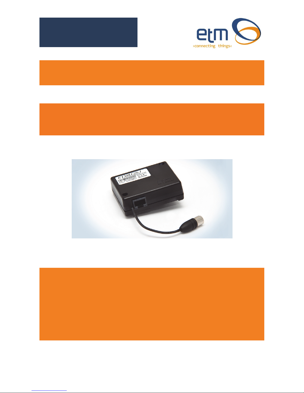
Overview.
The ETM8xxx-xxx range of products are compact industrial terminals designed for M2M (Machine
to Machine) communications.
Terminal Nomenclature/History
Model Comment Module Installed
ETM8120 Variants
ETM8120-1 RJ45 socket for serial and
power connection
TC63i
ETM8120-4 RJ45 plug on approx. 120mm
cable for serial and power
connection
TC63i
ETM8130/8140 Variants
ETM8130-1 RJ45 socket for serial and
power connection
EU3-P
ETM8140-1 RJ45 socket for serial and
power connection
PHS8-P
ETM8140-4 RJ45 plug on approx. 120mm
cable for serial and power
connection
PHS8-P
Applications
Typical applications include:
◩ General M2M communications device
◩ Automated Meter Reading (Telemetry)
◩ Interface to data acquisition/data logging systems
◩ Interfacing with alarm and control applications
◩ Temperature monitoring and alarm
◩ Water metering
◩ Rainfall monitoring
Page 4 of 17 For Support Contact +61-2-9956-7377
Or support@etmpacific.com.au
ETM8100 Series Quick Start GuideV002
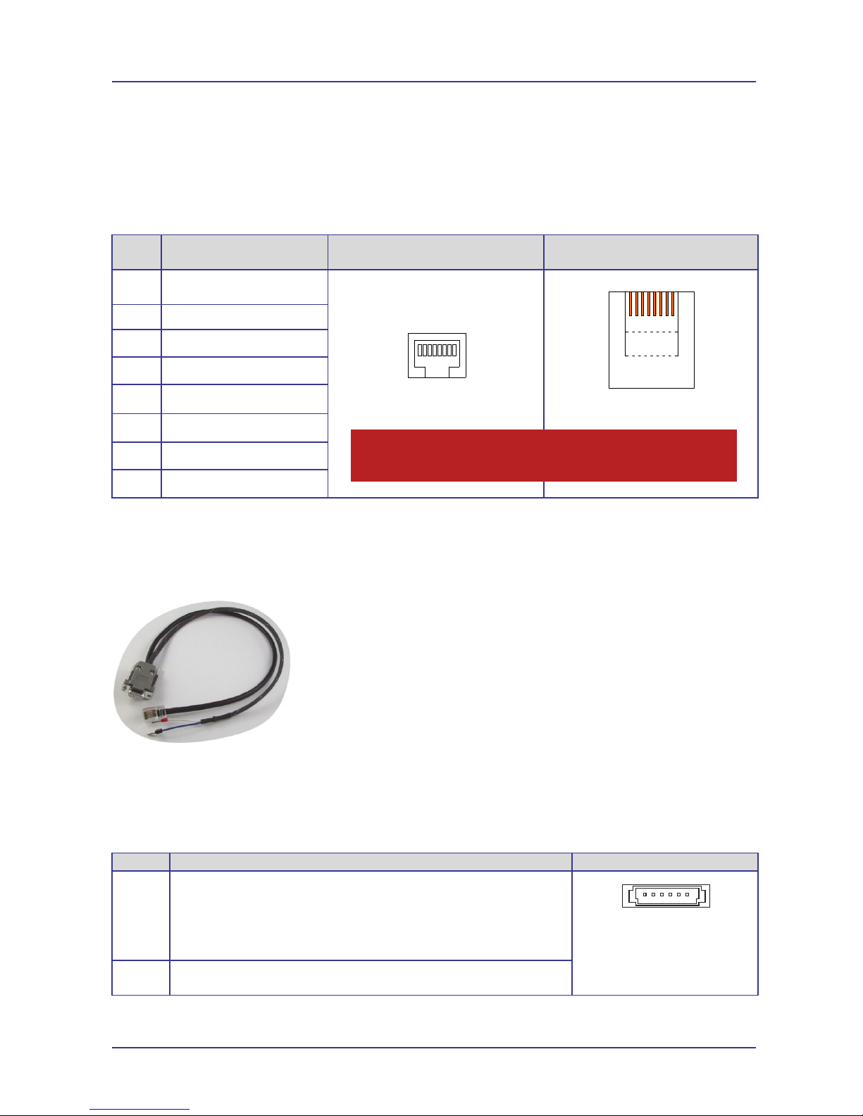
Power & Serial Connector, RJ45
The ETM8xxx-xxx modems utilise a single RJ45 socket (or plug for -4 versions) for connection of
serial interface and power.
The RS232 Port is the primary interface for the application software and connection to external
devices. ET/AT commands are used to communicate with the terminal.
Pin Function Looking at Modem Socket
ETM8xxx-1
Looking at RJ45 Plug
ETM8xxx-4 (Hook underneath)
1 Power Supply
(+4 to +35VDC)
12345678
12345678
2 DCD
3 DTR
4 GND
5 RX
6 TX
7 CTS
8 RTS
RJ45/DB9F/Flying Lead Adaptor Cable
The following adaptor cable is available from ETM for ease of connection to the modem when
programming and testing.
Adaptor Cable for Programming ETM8xxx-xxx Modems
White/red positive +4 to 35VDC blue/black Negative/Gnd
ERNI 6 Pin Minibridge I/O Connector (if fitted)
If fitted 4 x I/O’s configurable as digital, analogue or pulse are available on the ERNI 6 Pin
Minibridge IO connector, pin allocations are as shown below.
Pin Function Looking at Modem Socket
1 to 4 Configurable as:
◩ Digital Input: LL<0.5V, HL>2.5V, Max Input 50VDC
◩ Digital Output: LL0V, HL3V,0.1mA
◩ Pulse Input (I/O9): LL<0.5V, HL>2.5V, Max Input 50VDC
◩ Analogue Input: 0-2.5VDC, Max Input 50VDC
ERNI 1.27mm Minibridge
Connector
5 & 6 GND
Caution
This modem has no reverse polarity protection on the power input, incorrect
connection of power may damage the modem
1 2 3 4 5 6
Page 5 of 17 For Support Contact +61-2-9956-7377
Or support@etmpacific.com.au
ETM8100 Series Quick Start GuideV002
Antenna
The ETM8xxx-xxx Terminal has a standard FME M antenna Plug on the end of an approximately
120mm cable.
FME M Antenna Connector
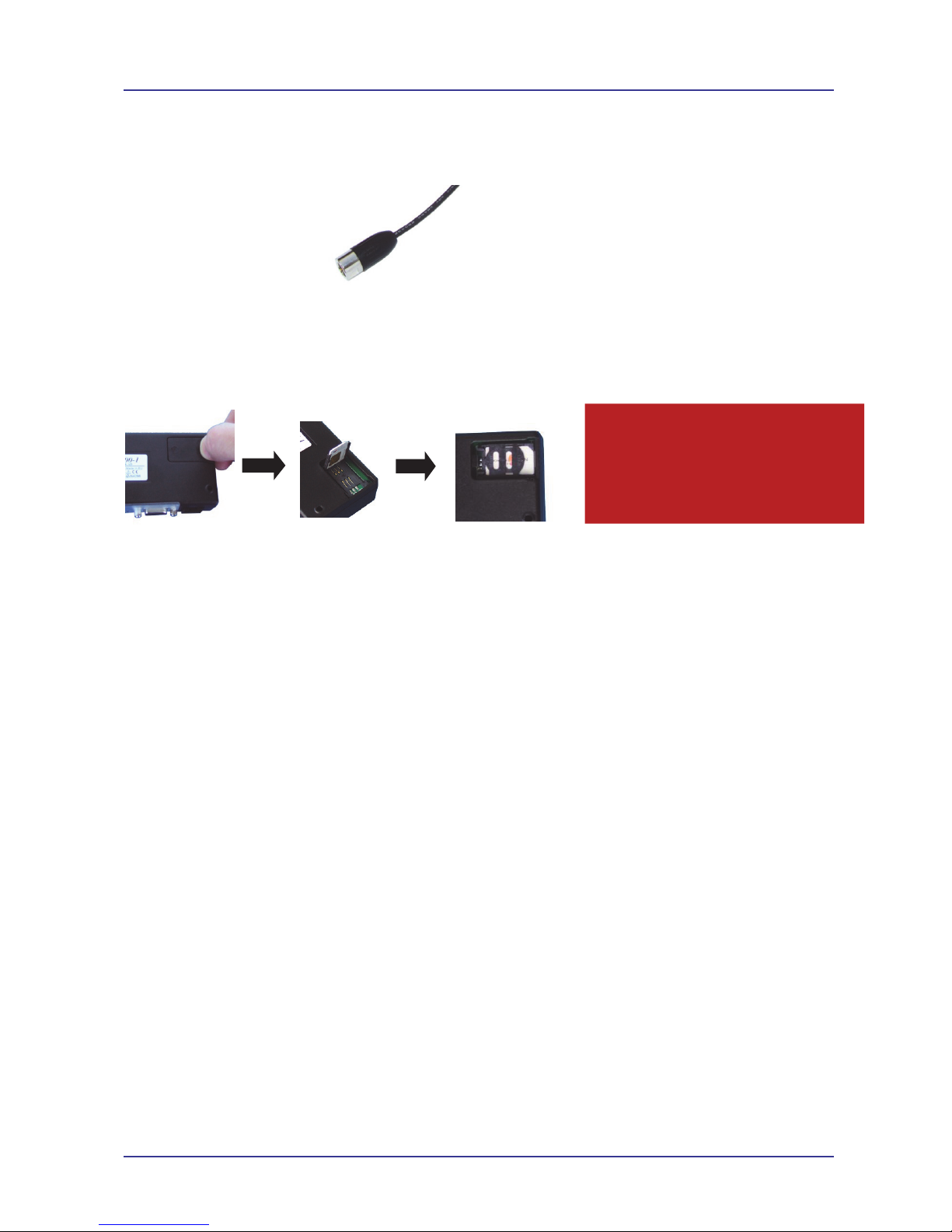
SIM Card
The SIM card connector is located on the underside of the ETM8xxx-xxx Terminal. The unit
supports both 3V or 1.8V SIMs. Any SIM card used needs to be correctly provisioned for the
services and network upon which it is intended to be used.
If the terminal is intended to be used for remote access to a device a terminating data number for
Circuit Switch Data (CSD) MAY need to be provisioned by the network operator, this number will
usually differ from any voice/SMS number, eg for Telstra;
◩ Telstra NextG® SIMs when used for CSD requires 2620 bearer capability
SIM Pin
If the SIM used has a PIN either;
The unit can be configured to enter the SIM pin, refer configuration tool section
OR
The SIM PIN should be deactivated, insert the SIM in a mobile phone and deactivate then
transfer the SIM into the ETM8xxx-xxx unit.
Caution
Always disconnect power supply before
inserting or removing SIM Card.
Care should be taken in inserting and
removing the SIM card so as not to
dama
g
e the SIM holder or cover.

Page 6 of 17 For Support Contact +61-2-9956-7377
Or support@etmpacific.com.au
ETM8100 Series Quick Start GuideV002
Indicator Lights
LED indication during runtime
BLUE Status 1 LED signal from the Module. LED is flashing when the ME is registered to the network
and either awake or in power saving state.
YELLOW Busy with communication and waiting for answer from the Module. Socket Established
indication.
GREEN Status 0 LED signal from the Module. LED is flashing when the ME is registered to the network
and either awake or in power saving state.
BLUE LED mode (UMTS) Function
500ms On / 500ms Off
Limited Network Service: No SIM card inserted or no PIN entered, or network
search in progress, or ongoing user authentication, or network login in
progress.
40ms on / 3990ms off
LED flashes when the ME is registered to the UMTS network and either awake
or in power saving state.
Off
ME is not registered to the UMTS network.
75ms on / 75ms off /
75ms on /1990ms off
One or more UMTS PDP contexts activated.
YELLOW LED mode Function
Flashing Busy with communication with the Module.
0.5s On / 0.5s Off Waiting for answer from the Module.
On When connected to an ISP and a Socket is established.
GREEN LED mode (GSM) Function
600ms On / 600ms Off Limited Network Service: No SIM card inserted or no PIN entered, or
network search in progress, or ongoing user authentication, or network
login in progress.
75ms on / 3s off IDLE mode: The mobile is registered to the GSM network (monitoring
control channels and user interactions). No call is in progress.
75ms on / 75ms off /
75ms on /3s off
One or more GPRS PDP contexts activated.
500 ms on / 50 ms off Packet switched data transfer is in progress.
Off ME is in one of the following modes:
- POWER DOWN mode
- AIRPLANE mode
- CHARGE ONLY mode
- NON-CYCLIC SLEEP mode
- CYCLIC SLEEP mode with no temporary wake-up event in progress
On Depending on type of call:
Voice call: Connected to remote party.
Data call: Connected to remote party or
exchange of parameters while setting
up or disconnecting a call.
BLUE
YELLOW GREEN
ETM8100 STATUS LEDs
UMTS MCU Status GSM
 Loading...