

Page 1
1 / 36
Secual Box V2
User Manual
www.etiger.c om
Page 2

2 / 36
Contents
Box contents ....................................................................................................................................... 3
Design .................................................................................................................................................. 3
Features ............................................................................................................................................... 4
Specifications ...................................................................................................................................... 4
Setup
Wi-Fi network settings ........................................................................................................ 6
Step 1: Insert a SIM card in the control panel....................................................................... 7
Step 2: Turn the control panel on ........................................................................................ 8
Step 3: Install App and create account ................................................................................. 8
Step 4: Connect to control panel’s AP .................................................................................. 9
Step 5: Connect control panel to home’s WiFi ...................................................................... 9
Step 6: Connect control panel to the Server ....................................................................... 10
Settings
APP operations .................................................................................................................................12
Change a detector’s zone.................................................................................................................19
Reset Wi-Fi ........................................................................................................................................19
Restore default settings ...................................................................................................................19
Daily use
Arm the system.................................................................................................................................21
Arm in Home mode ..........................................................................................................................21
Disarm the system ............................................................................................................................22
SOS function......................................................................................................................................22
Control by phone call .......................................................................................................................23
Accessories
Pet-immune Motion sensor (ES-D2A) ............................................................................................25
Door / Window Detector (ES-D3D) .................................................................................................28
Remote control (ES-RC1N) ...............................................................................................................30
Connecting additional accessories .................................................................................................31
Precautions
Precautions .......................................................................................................................................33
Warning .............................................................................................................................................34
Normes ..............................................................................................................................................35
Page 3
3 / 36
Box contents
- Control panel x1
- ES-D2A (Pet-immune motion sensor) x1
- ES-D3D(Door/Window contact) x1
- ES-RC1N (Remote controls) x2
- AC Adapter x1
- crews and anchors
- Documentation
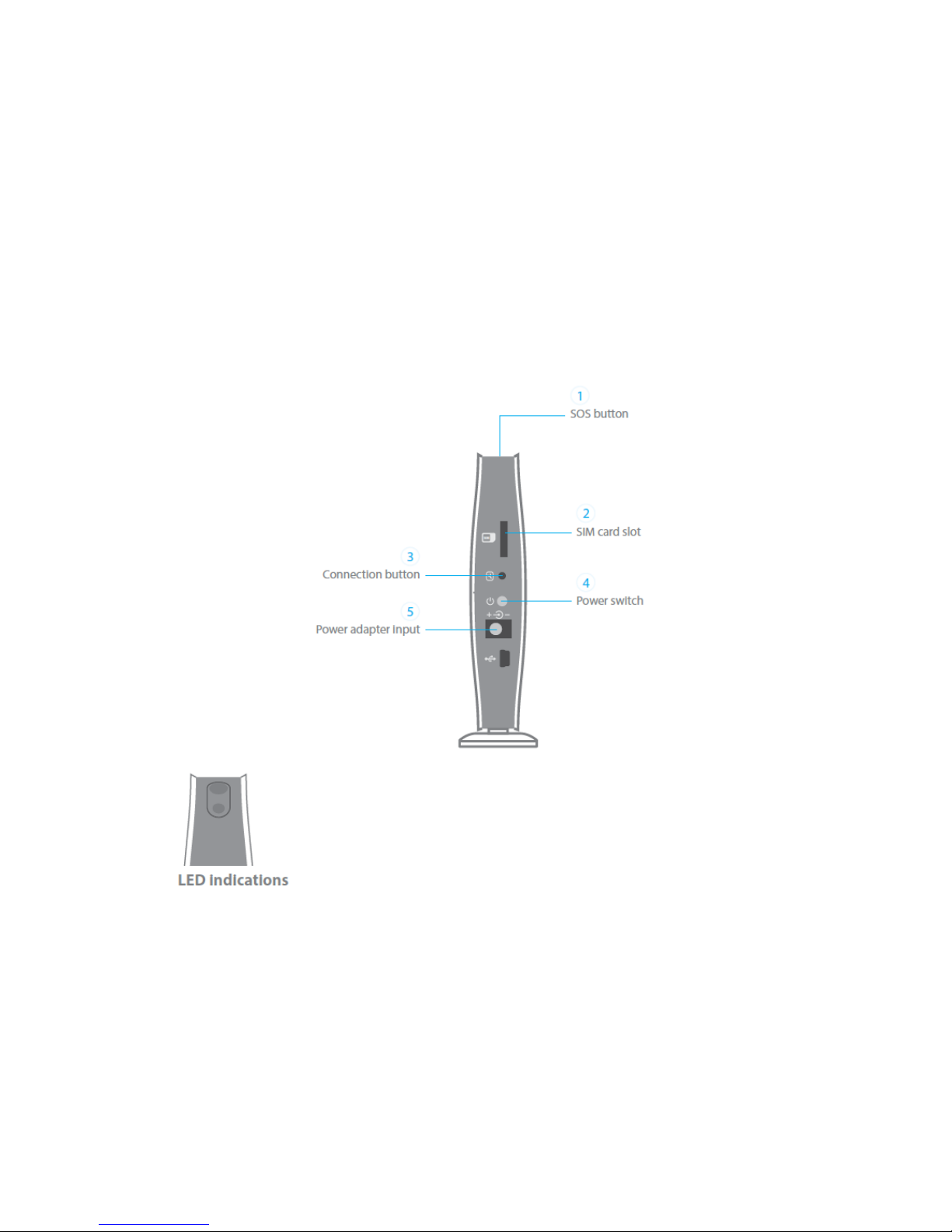
Design
Top: Status Indicator
Blue fixed: system armed
Blinking blue: Home mode
Blinking slowly white: connected to GSM signal
Blinking rapidly white: not connected to GSM signal
Bottom: Power / Network Indicator
Green fixed only: Not connected to Wi-Fi router
Green + Blue(Continuous): Connected to Wi-Fi router
Page 4

4 / 36
Features
- Works with an Internet Connection (Wi-Fi Connection)
- Control and setup of the system on your smartphone (Android or iOS app)
- Notifications in case of alert and system status change
- SIM card slot: stay connected even where you don’t have an Internet connection
or when your home Wi-Fi network is down (SIM card not included)
- Supports up to 10 remote controls, 100 wireless accessories with secure connection
- Can store up to 5 phone numbers, 5 SMS numbers (SIM card required for
communication by SMS and phone call)
- Built-in 95 dB siren and backup batteries (lithium, 7.4V 500mAh, up to 8 hours in
standby mode)
Specifications
- Product name: Secual Box V2
- SKU: ESB-WS2A
- Power supply: Input:AC 100-240V/50-60 Hz Output: DC 12V/1A
- Wi-Fi: 802.11 b/g/n
- Radio-frequency: 433.92MHz
- Backup battery: Lithium, 7.4V 500mAh,
- Static current: ≤60 mA
- Alarm current: ≤120 mA
- Internal siren: 95dB
- Housing material: ABS plastic
- Operating conditions: -10 ~ 55 C, humidity <80%(non-condensing)
- Dimensions (L x W x H): 150 x 49 x 160 mm
Page 5
5 / 36
Setup
Page 6

6 / 36
Wi-Fi network settings
The Secual Box can work with a Wi-Fi connection, a SIM card or both.
- Wi-Fi connection: enables you to interact with your control panel by
app (iOS / Android). All you need is a Wi-Fi connection at home and an
Internet connection on your smartphone (Wi-Fi, 4G, 3G).
- Wi-Fi connection + SIM card (GSM network): offers optimal security: you
have a backup in case your home Wi-Fi or your cellular network is down.
- SIM card only: enables you to interact with your control panel by SMS and
phone call. You do not need to have an Internet connection at home or
on your smartphone. Some of the app's features will not be available.
Page 7
7 / 36
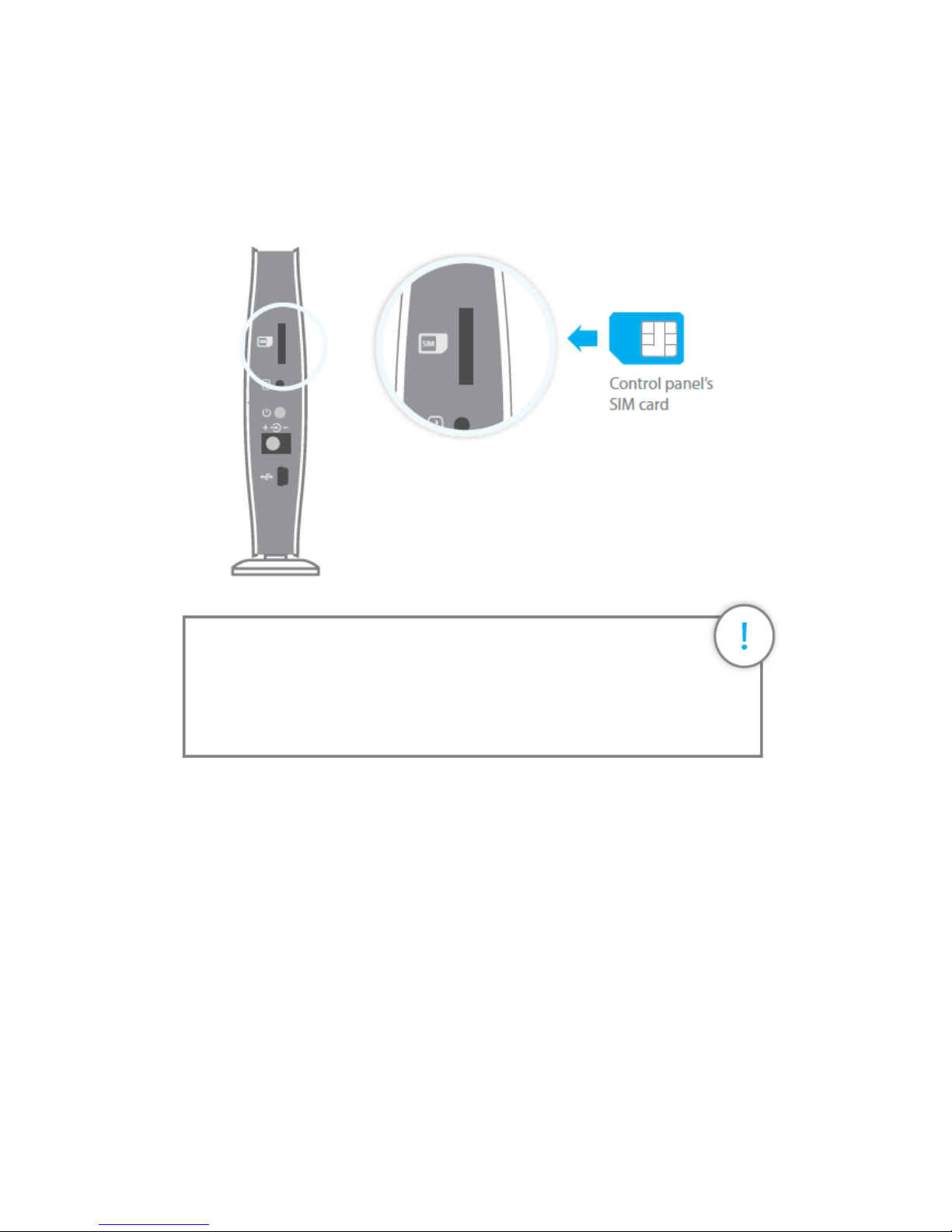
Step 1: Insert a SIM card in the control panel
This step applies only if you wish to use the Secual Box with a SIM card.
You will need a SIM card if you wish to interact with your Secual Box by SMS and
phone call.
Important
- Make sure the SIM card is not protected by a PIN code.
- We advise you to choose a plan with unlimited text and 1 or 2 hours
of call. The SIM card must be compatible with the GSM network.
Contact your carrier for more information.
Page 8
8 / 36
Step 2: Turn the control panel on
1. Plug the power adapter to AC socket.
2. Plug the output connector of the power adapter into the AC adapter interface.
3. Push the power switch.
Step 3: Install App and create account
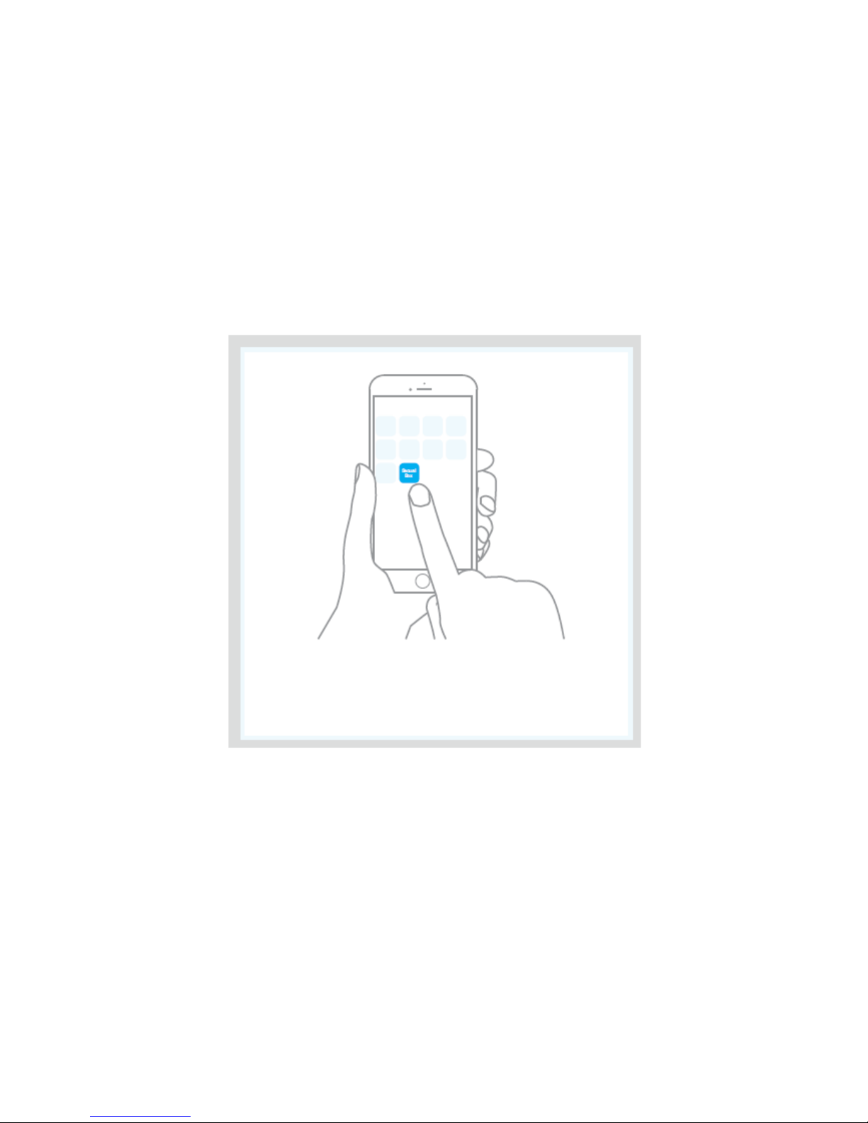
1. Download the “Secual Box V2” app on your smartphone. The app is available on the
App Store and Google Play.
2. Connect your phone to your home’s Wi-Fi router.
3. Open the “Secual Box V2” app on your smartphone.
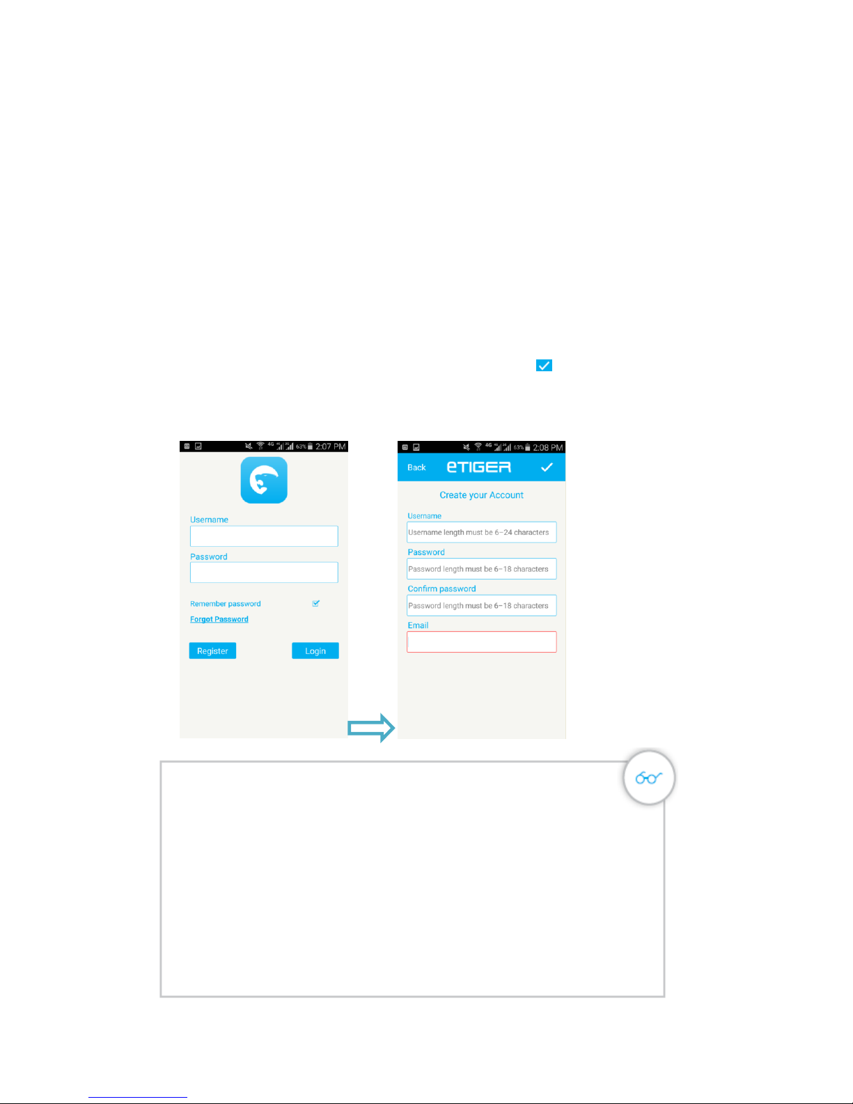
4. Click “Register” to enter “Create your Account” interface.
5. Fill the Username, Password and Email in the fields, click “ ” to save the
information.
6. After register successful, enter the “Username” and “Password”, click “Login” to
enter the APP.
A piece of advice
Even if your control panel is connected to your Wi-Fi network, you
can add a SIM card in your Secual Box. This enables you to receive
notifications by SMS and phone calls, which can be very useful when
you do not have an Internet connection on your smartphone when the
alarm is triggered.
If the Wi-Fi network of the Secual Box is secured
Reset the Secual Box's Wi-Fi by pressing the Connection button 3 of
the control panel for 5 seconds. The control panel beeps 3times, as a
confirmation that it has reset successfully.
Page 9
9 / 36
Step 4: Connect to control panel’s AP
1. Before you setup the Wi-Fi connection of the alarm system please make sure you are
logged in in the APP.
2. Go to your Smartphone WiFi settings without closing the APP.
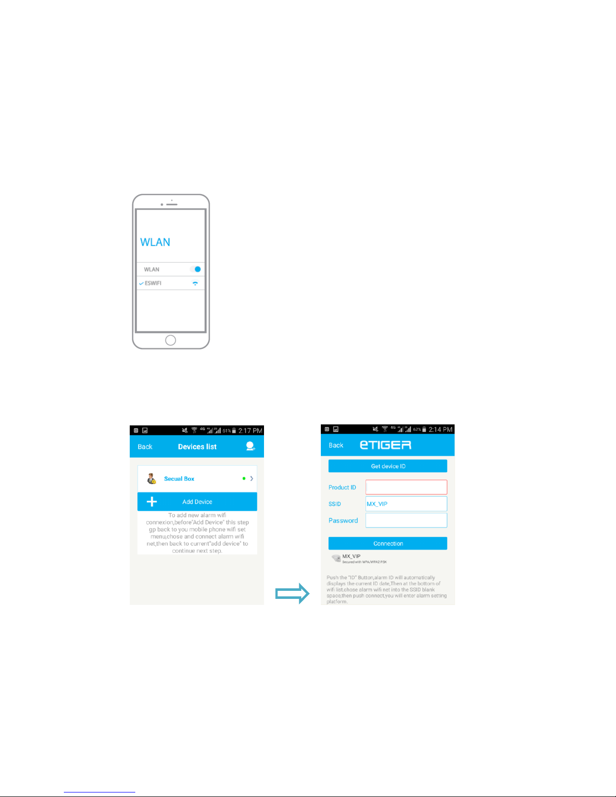
3. Connect the Smartphone to the alarm systems own Wi-Fi network(SSID: ESWIFI. If
the ESWIFI is secured, you can reset the WIFI to factory settings by long press the
connection button 5seconds until you hear 3beeps ).
4. Go back to the APP, wait for the notification WiFi now in use.
Step 5: Connect control panel to home’s WiFi
1. Now from the APP account select “ + Add device”.
2. “Product ID”: If your smartphone is connected to the Wi-Fi network of the alarm
system the APP will detect the Product ID of the alarm, if this is not the case please
press “Get device ID” to request the Product ID.
3. “SSID”: After APP detect the Product ID, select the WiFi connection you wish to
connect the alarm system to from the list of available WiFi networks.
4. “Password”: Enter the password of the WiFi networks(Your router’s password that
the alarm will connected to).
5. Press “Connection” and wait for 20 seconds to get a response.
Page 10
10 / 36
Step 6: Connect control panel to the Server
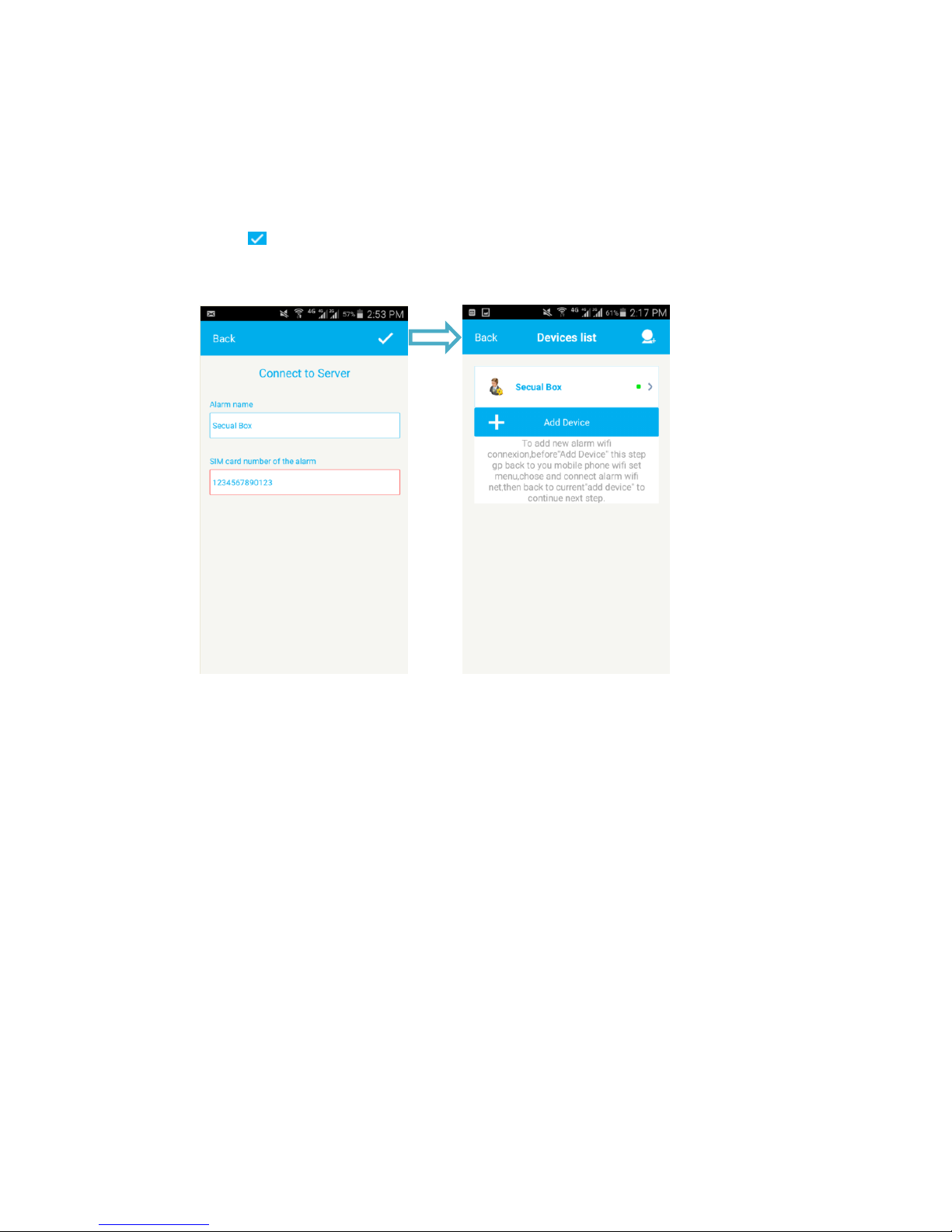
1. “Alarm name”: Enter a name for the control panel.
2. “SIM card number of the alarm”: Enter the mobile number of the SIM card installed
in the alarm system. This will enables you control the alarm system via SMS.
3. Press “ ” to save the settings. After setting successful, you will find the “control panel”
in the Devices list. Now you can select the Alarm name to enter the operation interface
to control your alarm system.
Page 11
11 / 36
Settings
Page 12
12 / 36
APP operations
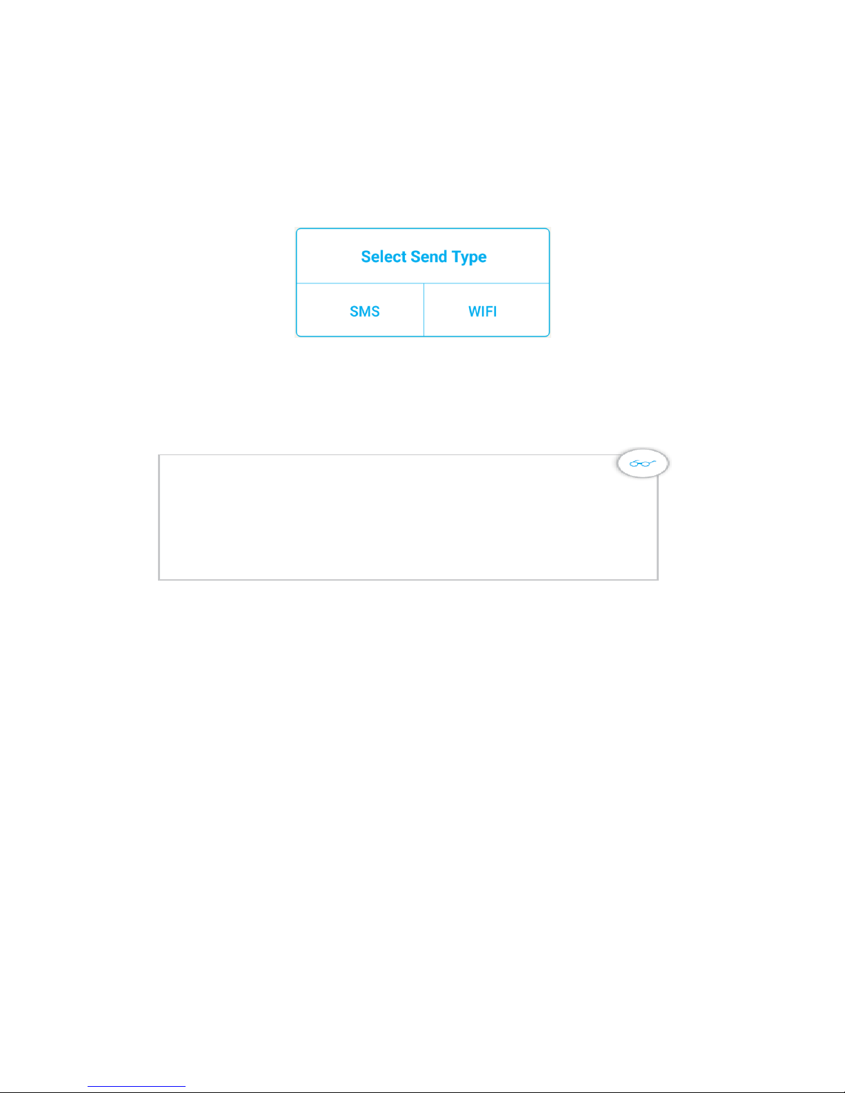
Select Send Type
The APP enables you control your Secual Box via WiFi or SMS, select the send type which you
want to use for changing the settings.
SMS: Control the Secual Box via SMS.
WIFI: Control the Secual Box via WiFi network.
Control the Secual Box via SMS
- Make sure you have set the “SIM card number of the alarm”
- The Secual Box with a SIM card
- You have save your phone number in the Secual Box
Page 13
13 / 36
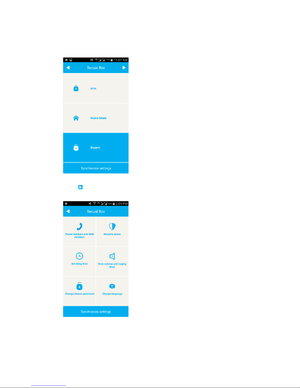
1. Arm, Home Mode or Disarm the system.
Click alarm name to enter the operation interface. In this page you can control your
alarm via the APP.
2. System Settings
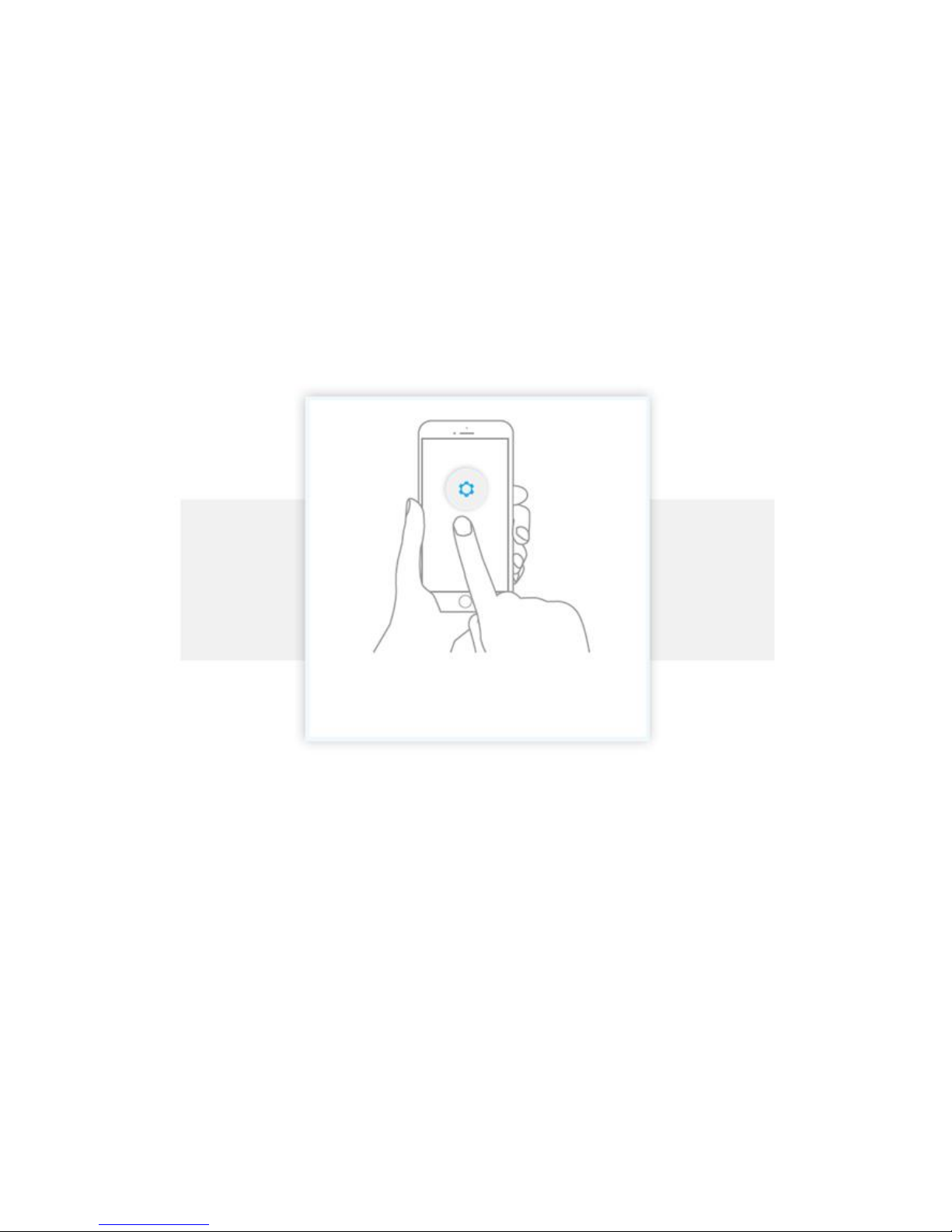
Click “ ” to the second page “Setting interface”, in this page you can
modify the settings of your alarm via the APP.
Page 14
14 / 36
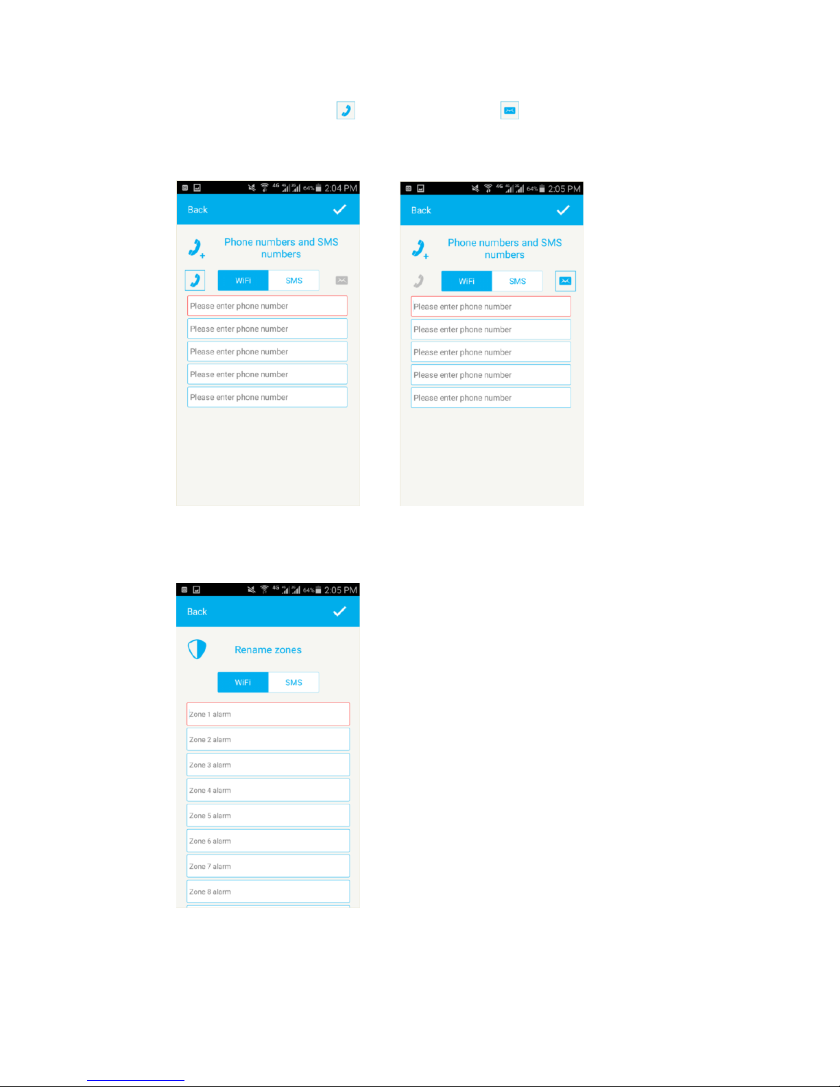
2.1 Save Phone numbers and SMS numbers
This function enables you to determine the telephone numbers that will be
called or receive SMS by your alarm in case of alert.
2.2 Rename zones
Zone 1~9 can be renamed, The name of the zone cannot consist of more
than 16 latin characters.
Page 15
15 / 36
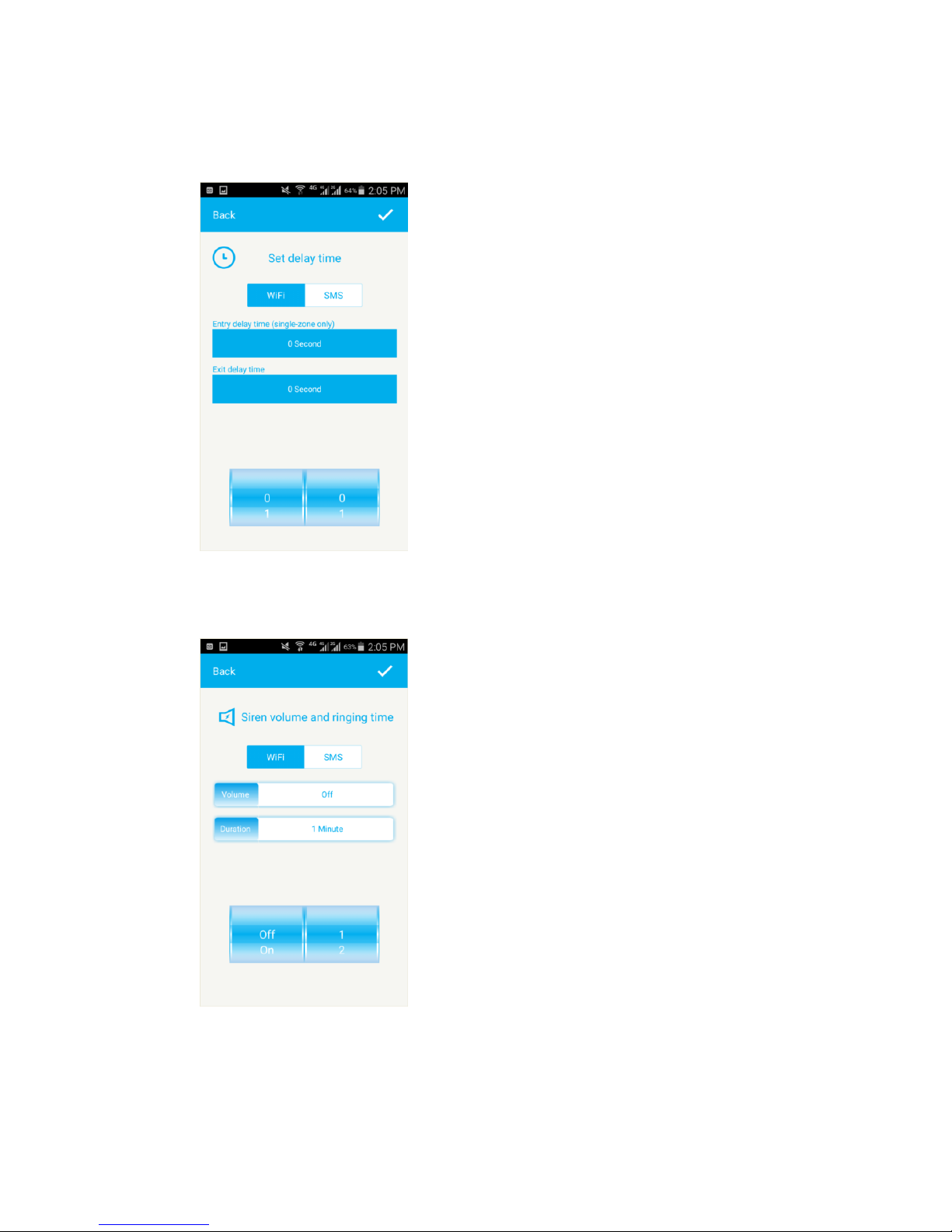
2.3 Entry / Exit delay
This function enables you to determine a delay when you leave or enter
your home during which detectors will not trigger the alarm.
2.4 Siren setup
This function enables you to switch on/off the siren, and you can set
the siren duration time from 1 to 9 minutes.
Page 16
16 / 36
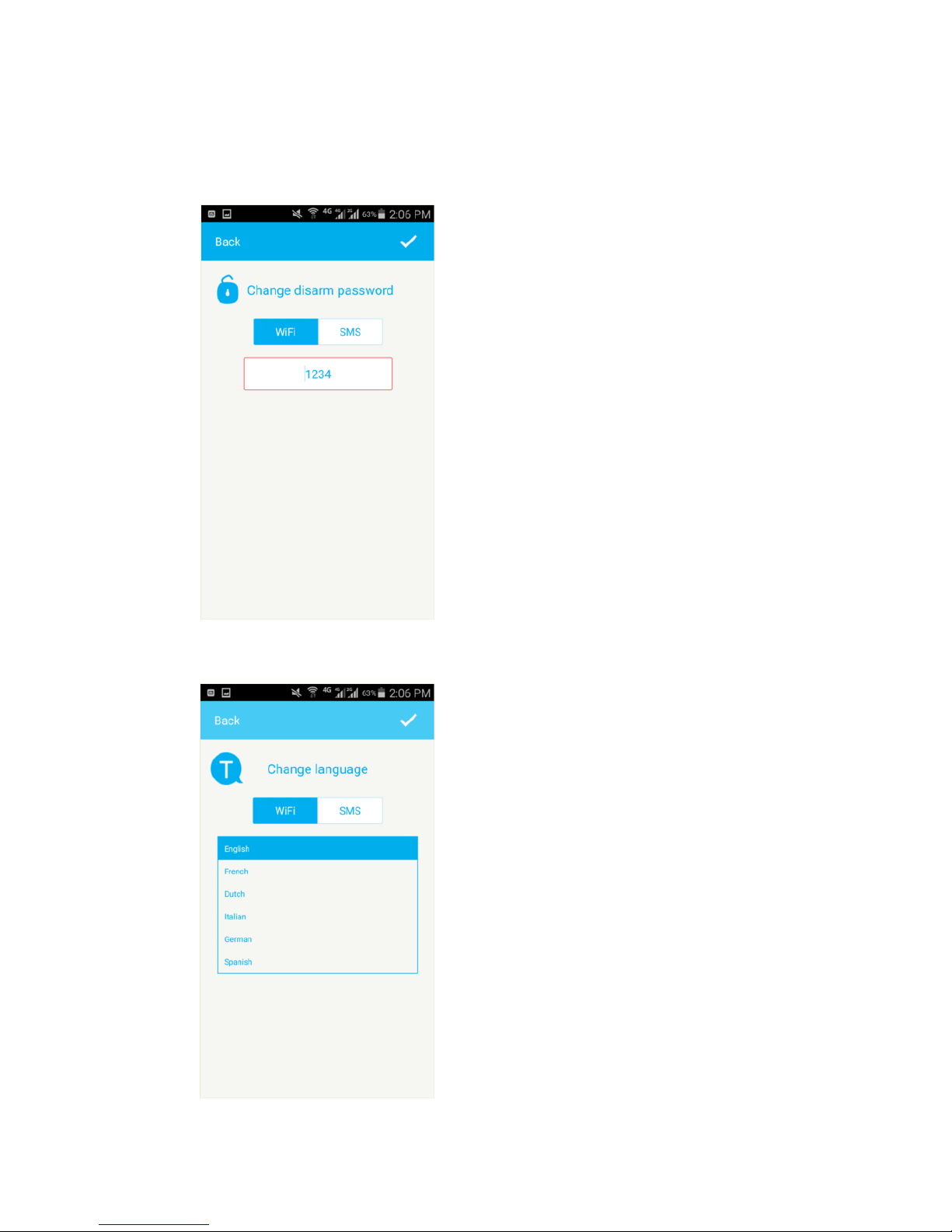
2.5 Change Password
This function enables you to check and modify the system password. The
password is requested when you want to control your control panel by
phone call.
2.6 Change system language
This function enables you to check and modify your system language.
Page 17
17 / 36
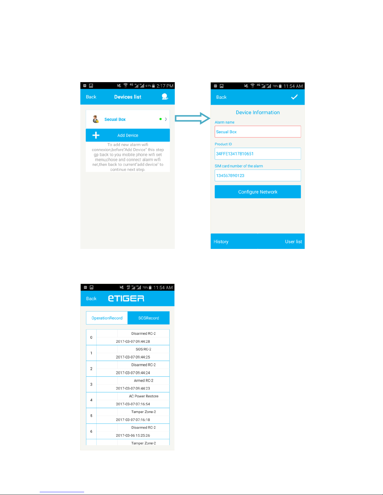
3. Device Information
Long press Alarm name to enter “Device Information” interface, in this
page you can modify the “Alarm name” and “SIM card number” , check the
History and manage the User List..
3.1 Check system History
This function enables you to check the Operation and Alarm record of
the system.
Page 18
18 / 36
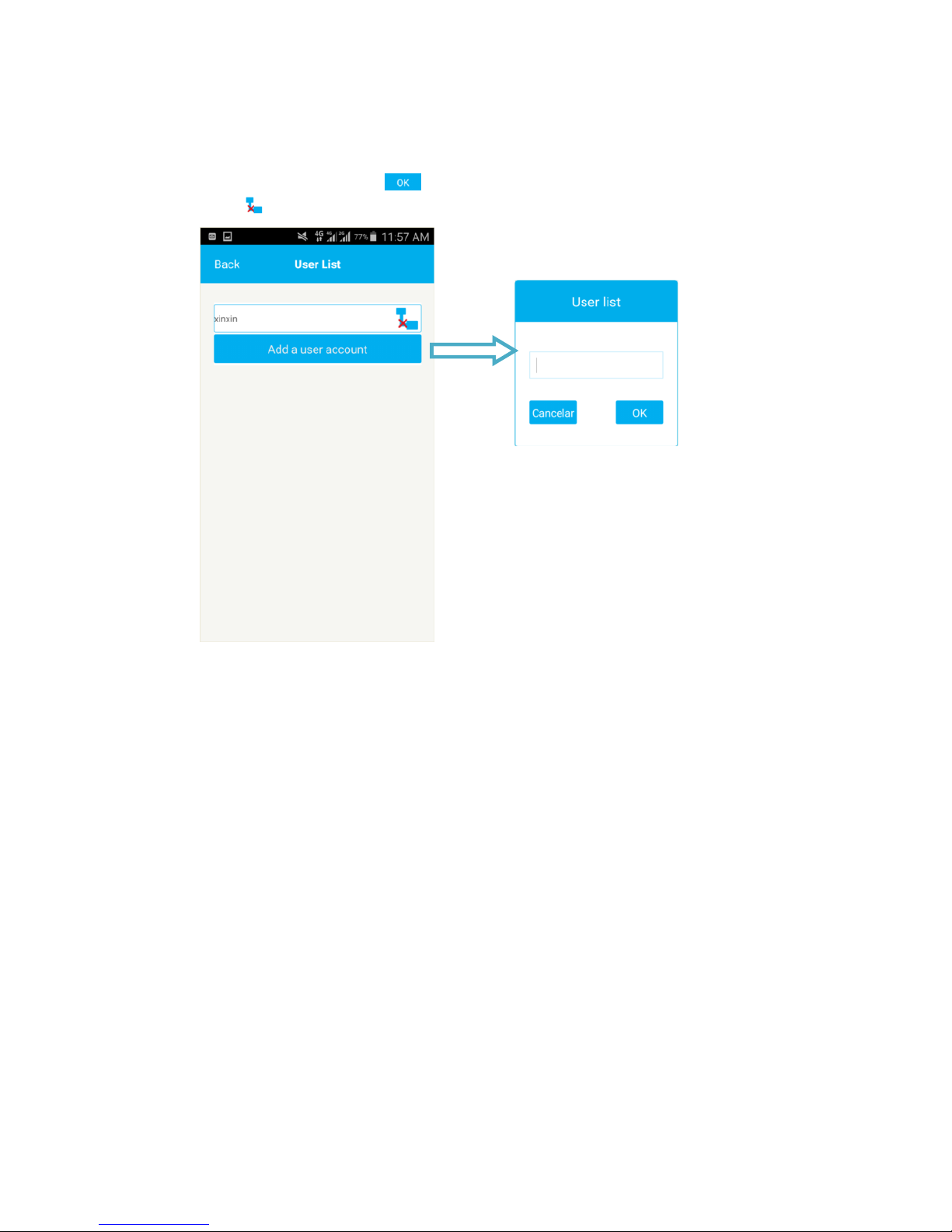
3.2 Manage Gust Account
In User List interface, you can add other user account for who can control
the Secual Box as a gust. Click “ Add a user account”Enter the user’s
APP account and click “ ” to save. If you want to delete the gust user,
click “ ”.
Page 19
19 / 36
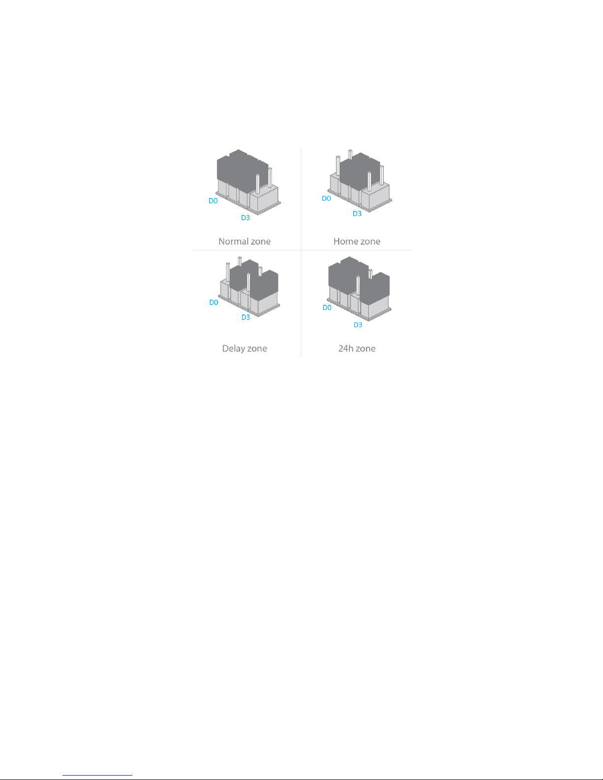
Change a detector’s zone
You c an mod if y th e zon e of a d etector by moving the jumpers with tweezers,
according to the drawings below. The jumpers are located on each detector’s
circuit board.
What do zones do?
Normal zone: when the system is armed, a detector on the Normal zone is
active. When the system is disarmed, the detector is not active.
Home zone: when the system is armed in Home mode, all detectors are active
except those assigned to the Home zone.
Delay zone: only detectors on the Delay zone will be impacted by the entry
delay.
24h zone: a detector on the 24h zone is always active, regardless the system
is armed or not.
Reset Wi-Fi
If the Secual Box is secured or you want to change the network of your control
panel, you can reset the W i-Fi by press the connection button of the control
panel for 5 seconds. The control panel beeps 3times, as a confirmation that it
has reset successfully.
Restore default settings
Press and hold on the Connection button, then press the Panic button(SOS),
Release them after 3 beeps. Wait 10 seconds, the control panel beeps twice:
The system is restored to default settings.
The stored phone numbers and settings will be restored to factory settings, all
acc essories will be deleted f r om the control panel.
Page 20
20 / 36
Daily use
Page 21

21 / 36
Arm the system
When your system is armed, all detectors are active.
By app
Connect to your alarm and click on “Arm”.
By SMS
Send 1 by SMS to the phone number of the SIM card in the control panel.
Only saved SMS numbers can disarm the system by SMS.
By remote control
Press on the “Arm” button of the remote control ( ).
Arm in Home mode
When your system is armed in Home mode, all detectors are active except
those assigned to the Home zone.
By app
Connect to your alarm and click on “Home mode”.
By SMS
Send 2 by SMS to the phone number of the SIM card in the control panel.
Only saved SMS numbers can disarm the system by SMS.
By remote control
Press on the “Home” button of the remote control ( ).
Page 22

22 / 36
Disarm the system
When your system is disarmed, all detectors are inactive except those
assigned to the 24H zone.
By app
Connect to your alarm and click on “Disarm”.
By SMS
Send 0 by SMS to the phone number of the SIM card in the control panel.
Only saved SMS numbers can disarm the system by SMS.
By remote control
Press on the “Disarm” button of the remote control ( ).
SOS function
The SOS function enables you to trigger your alarm immediately.
By remote control
Press on the “SOS” button of the remote control (SOS).
On the control panel
Press the SOS button on the top of the control panel.
Page 23

23 / 36
Control by phone call
This function applies only if you are using the Secual Box with a SIM
card.
This function enables you to control your alarm system by phone call. This can especially
be helpful if you are located in an area without Wi-Fi or 3G/4G coverage.
How it works
1. Call the phone number of the SIM card in the control panel.
2. The control panel picks up: type your 4-digit passcode, followed by "#" (Default
passcode: 1234).
3. A voice prompt confirms if your code is correct.
4. On your phone, dial the code corresponding to the command:
Tabl e 1
Dial
Command
1
Arms the system
0
- Disarms the system and turns the siren off
- Stops monitoring without hanging up
*
Audio monitoring
6
Turns the siren off
9
Turns the siren on
#
Disarms the system, turns the siren off and ends the phone call
If your alarm is triggered
If the alarm is triggered, your control panel immediately starts to inform you:
At home
- The built-in siren starts ringing out.
- If you have connected additional sirens, they start ringing out too.
On your smartphone(if your alarm is connected to your Wi-Fi network)
- You receive a push notification in the Secual Box app (you must havee an Internet
access on your smartphone).
On your smartphone (with a SIM card in the control panel)
- The control panel sends an SMS notification to every SMS number save d.
- The control panel calls every Phone number saved. If you take that call, you can
decide to stop the siren, disarm the system or other functions as listed below, by
dialing the corresponding code in Table1.
Page 24
24 / 36
Accessories
Page 25
25 / 36
Pet-immune Motion sensor (ES-D2A)
Features
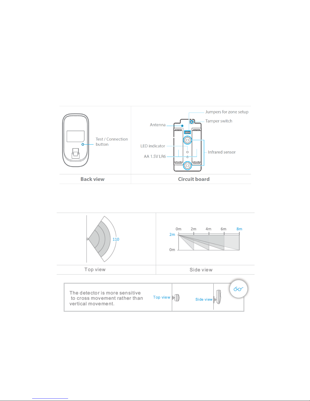
The ES-D2A is a high performance wireless motion detector boasting a digital dual-core
fuzzy logic infrared control chip with intelligent analysis. This technology identifies
interferences created by body motion and reduces the false alarm rate.
Design
Detection scope
Page 26
26 / 36
Mounting
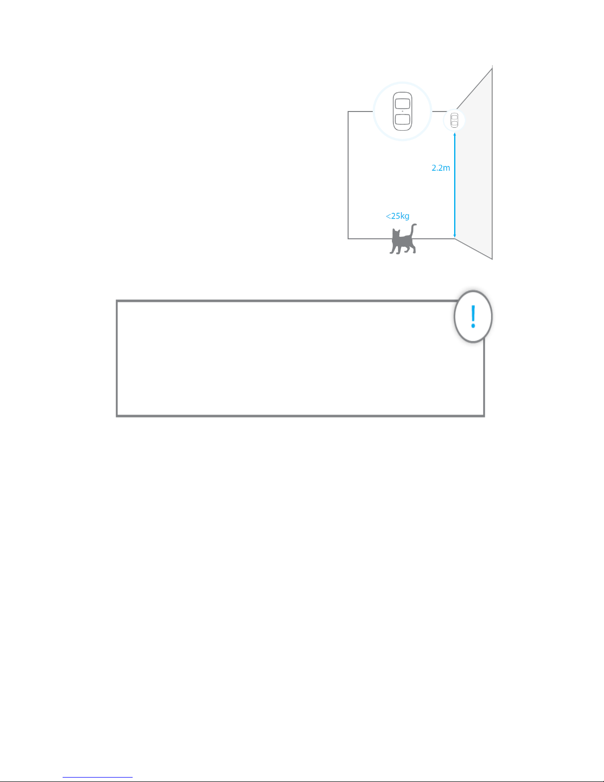
Fix the bracket onto the wall with screws and attach
the detector to the bracket. We recommend to
mount the detector at a height of 2.2m.
The detector is more sensitive to horizontal
movements than vertical movements, and does
not detect animals under 25 kg.
Avoid mounting the detector close to windows,
air conditioner, heater, refrigerator, oven,
sunshine and places where the temperature
changes fast or where the air stream flows frequently.
Testing
After installation, turn the detector on. After one minute of self-testing,press the test button,
walk in the scope of detection and watch the LED indicator to make sure the detector is
working. The LED indicator blinks once when a movement is detected.
LED indications
Blinks continuously: self-testing
Blinks once: Motion is detected
Blinks twice: self-testing is complete; entering working mode Blinks once every 3 seconds:
the batteries must be replaced.
Important: understanding the standby mode
If the detector is triggered more than twice within 3 minutes, it switches
to standby mode to save power. During standby mode, the detector is
inactive. If within the next 3 minutes a new movement is detected, the
standby mode is extended by 3 minutes. If no movement is detected
within the next 3 minutes, the sensor is activated again.
Page 27

27 / 36
Connection to your alarm system
The detectors in your kit are already connected and ready to use. If you have deleted the
detector from the control panel, you can reconnect it as follows:
1.Press once on the Connection button located on the control panel.
2.Press the Test button at the back of the detector. The control panel will beep once
acknowledging the connection. If the control panel beeps twice, the detector was
already connected.
Specifications
Power supply: DC 3V (AA 1.5V LR6 Batteries x 2)
Static current: ≤ 30 uA
Alarm current: ≤ 15 mA
Detection scope: 8 m / 110°
Transmission distance: ≤ 80 m (in open area)
Radio-frequency: 433.92 MHz (±75KHz)
Housing material: ABS plastic
Operating conditions: Temparature: -10°C~55°C Relative humidity: ≤ 80%
(noncondensing)
Dimensions (L x W x H): Detector: 107 x 53 x 32 mm, Bracket: 52 x 30 x 26.5 mm
Page 28
28 / 36
Door / Window Detector (ES-D3D)
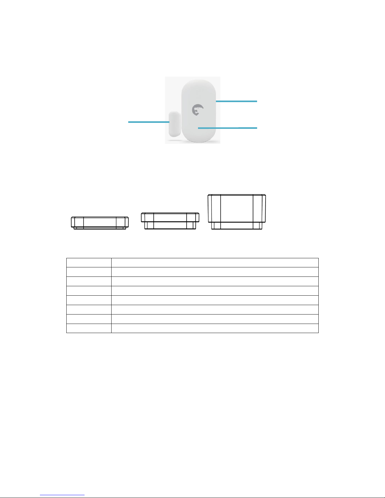
Design
Distance Holder
There are 3 sizes distance holder in the package, it is clickable to each to
reach more distance options, for different window frame depths where user will
mount the Magnet.
Heights(mm)
Holder
3
A
5
B
14.5
C
8
A+B
17.5
A+C
19.5
B+C
22.5
A+B+C
Magnet
LED indicator
Transmitter
A B C
Page 29

29 / 36
Mounting
Mount the magnet 1 cm away from the transmitter and secure the transmitter and magnet
with double-sided tape on the door and the door frame respectively.
Connection to your alarm system
The detectors in your kit are already connected and ready to use. If you have deleted the
detector from the control panel, you can reconnect it as follows:
1.Press once on the Connection button located on the control panel.
2.Separate the magnet of the detector from its transmitter. The control panel will beep
once acknowledging the connection. If the control panel beeps twice, the detector was
already connected.
Specifications
Power supply: CR2477 3 V Battery x1
Static current: ≤ 10 uA
Alarm current: ≤ 15 mA
Transmitting distance: ≤80 m (in open area)
Radio-frequency: 433.92 MHz (±75 KHz)
Housing material: ABS plastic
Operating conditions: Temparature: -10°C~55°C, Relative humidity: ≤ 80%
(noncondensing)
Dimensions (LxWxH): Transmitter: 55.7 x 30.3 x 16 mm, Magnet: 25 x 10 x 9 mm
LED indications
Blinks once: The door or window is open/close and the transmitter sends a signal to the
control panel.
Blinks quickly: Low power indication: the batteries must be replaced.
Page 30
30 / 36
Remote control (ES-RC1N)
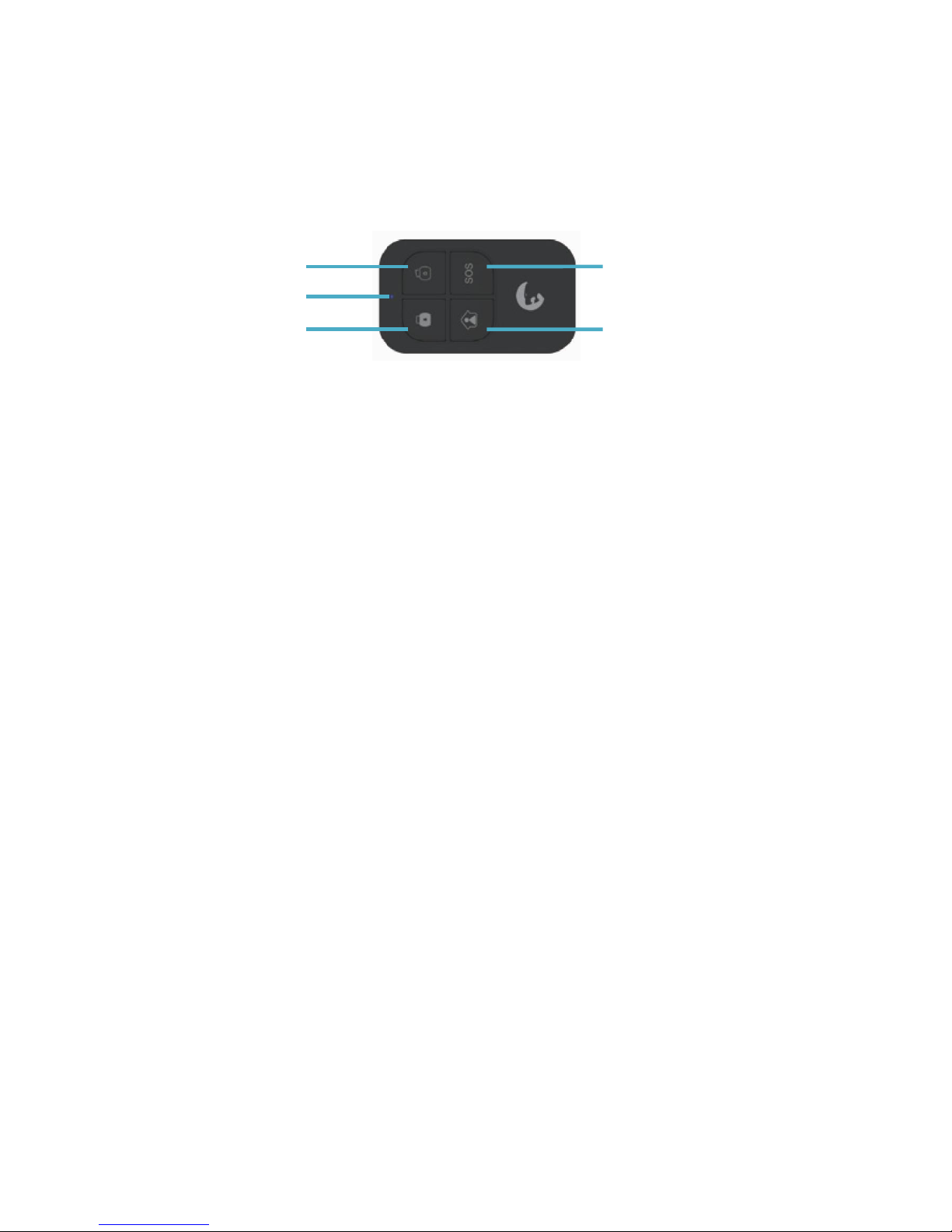
Design
Connection to your alarm system
The remote controls in your kit are already connected and ready to use. If you have
deleted a remote control from the control panel, you can reconnect it as follows:
1. Press once on the Connection button on the control panel.
2. Press the “Arm” button on the remote control.
3. The control panel will beep once acknowledging the connection. If the control panel
beeps twice, the detector was already connected.
Specifications
Power supply: DC 3V (CR2025 button battery x1)
Static current: ≤10 uA
Operating current: ≤7 mA
Transmission distance: ≤80 m (in open area)
Radio-frequency:: 433.92MHz (±75KHz)
Housing material: ABS plastic
Operating conditions: -10°C ~ +55°C, ≤80% (non-condensing)
Dimensions: 57 x 31 x 11 mm
Disarm
LED indicator
Arm
SOS
Home Mode
Page 31
31 / 36
Connecting additional accessories
Connecting additional detectors / controls
Additional sensors can be connected to the system. Sensor types include – Motion
Sensors, Pet Immune sensors and door window sensors. Syncing additional sensors
follows the same methodology as that mentioned above.
Connecting additional Siren
1. Press once on the Connection button on the Siren.
2. Press the “SOS” button on the control panel.
3. The siren will beep once acknowledging the connection. If the siren beeps twice, the
control panel was already connected.
Connect additional Peripherals
Outdoor Sirens/Indoor Sirens/Video Camera Not all sirens have the same way of
connecting. Please refer to the user manual of your siren to connect it to the hub.
A piece of advice
- Before connecting your siren to your control panel, make sure there is
no entry / exit delay set on the hub. If so, delete the delay during the
time of connection.
- While connecting the siren, make sure detectors are not triggered
Page 32
32 / 36
Precautions
Page 33
33 / 36
Precautions
For a safer use of the product and to optimize the lifespan of the product, we
recommend you to follow the precautions below:
- The wireless accessories must be connected to the control panel.
- Low power voltage may affect transmission distance.
- Do not press the SOS key on the remote control if it is unnecessary to avoid
disturbing neighborhood.
- Check the system regularly to make sure the system works properly.
- The control panel is neither waterproof nor moisture-proof, install it in a shady,
cool and dry place.
- The case of the control panel is made of ABS plastic. Keep away from bright light
for a longer lifespan.
- The control panel is not explosion-proof. Keep away from fire and flames.
- Dispose of the batteries according to local regulations.
- Dismantling of this product must be done by professional personnel only.
Important
Install the control panel away from objects such as ADSL box, TV set,
loudspeakers, heater, air conditioner, microwave oven etc. that generate
heat or electromagnetic fields.
Page 34
34 / 36
Warning
To prevent fire or shock hazards, do not expose this product to rain or moisture.
Apparatus shall not be exposed to dripping or splashing and no object filled with liquids,
such as vases, shall be placed on the apparatus.
ATTENTION
RISK OFELECTRIC
SHOCK
DO NOT OPEN
CAUTION: TO REDUCE THE RISK OF ELECTRIC SHOCK, DO NOT
REMOVE COVER (OR BACK). NO USER SERVICEABLE PARTS
INSIDE, REFER SERVICING TO QUALIFIED SERVICE
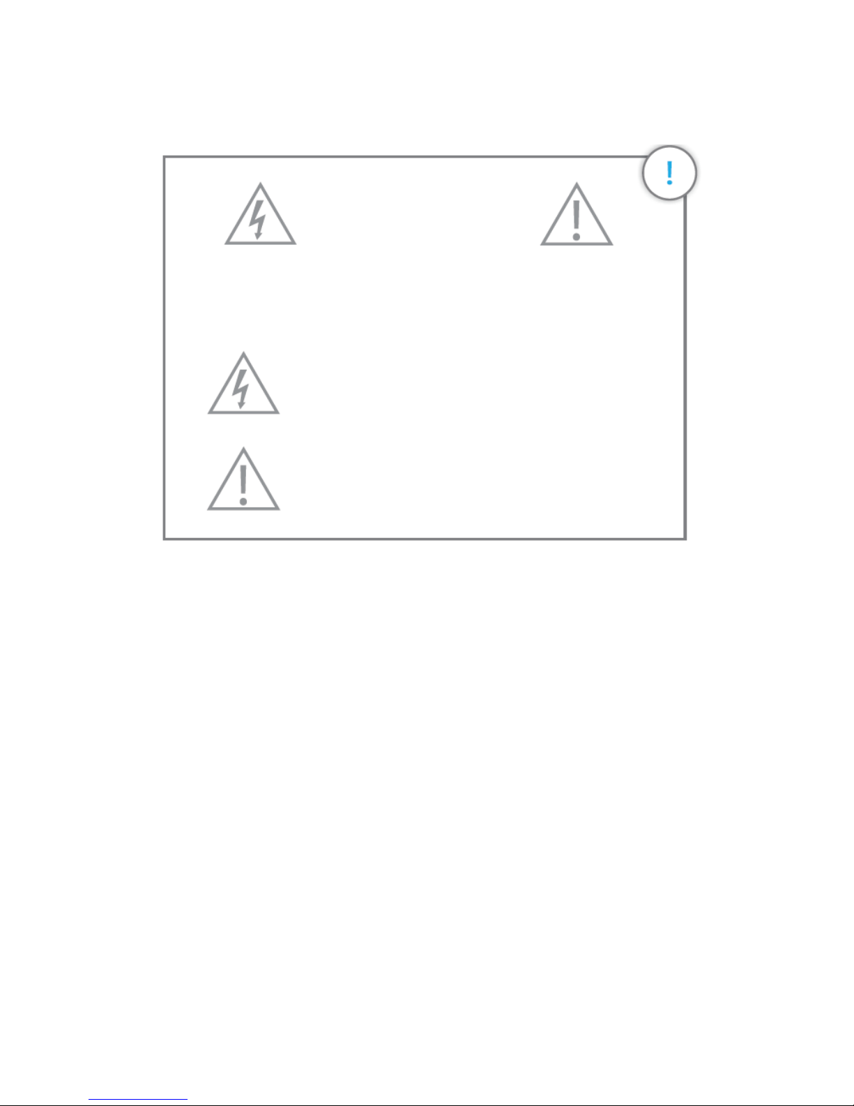
This symbol is intended to alert the user to the presence of
uninsulated “dangerous voltage” within the product’s
enclosure that maybe of sufficient magnitude to constitute a
risk of electric
The exclamation point within an equilateral triangle is
intended to alert the user to the presence of important
operating and maintenance (servicing) instructions in
the literature accompanying the product.
Page 35
35 / 36
Normes
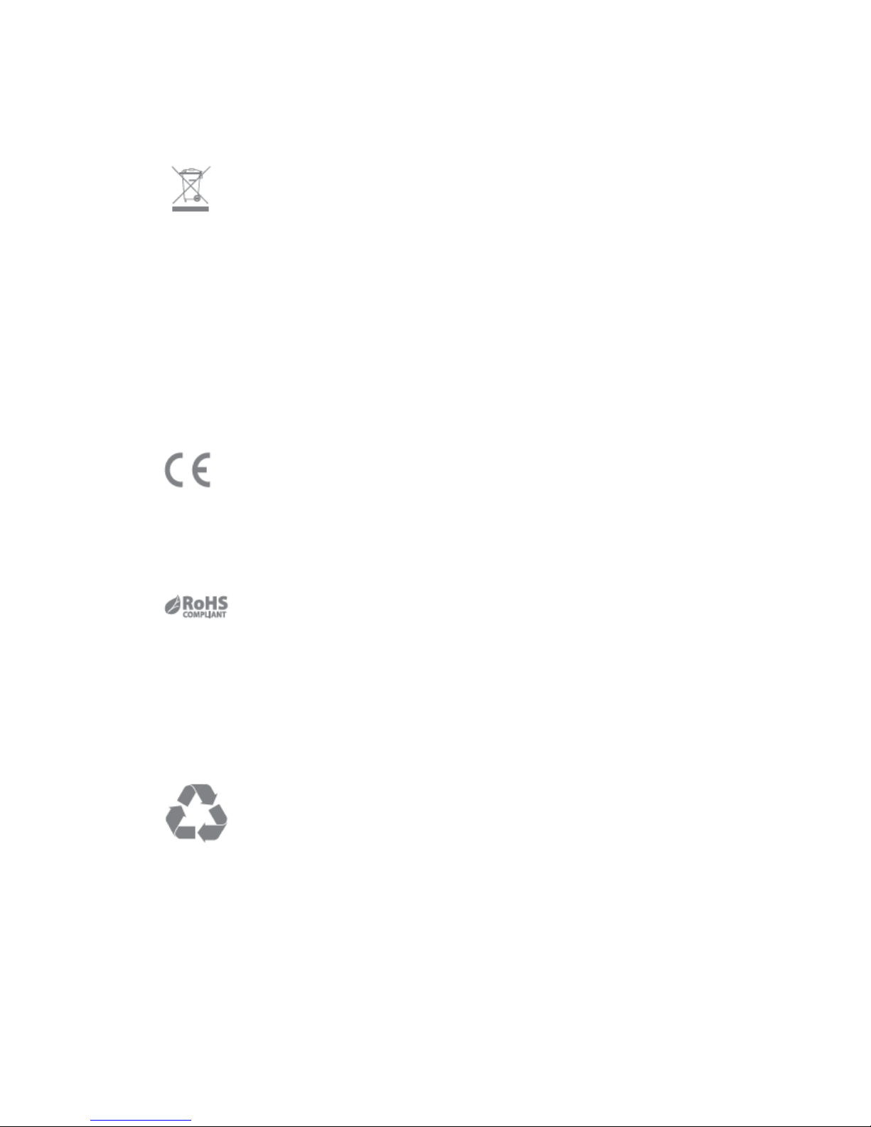
This product bears the selective sorting symbol for waste electrical and
electronic equipment (WEEE). This means that this product must be handled
pursuant to European Directive 2002/96/EC in order to be recycled or dismantled
to minimize its impact on the environment.
For further information, please contact your local or regional authorities.
Electronic products not included in the selective sorting process are potentially
dangerous for the environment and human health due to the presence of
hazardous substances.
In compliance with European laws. This product is in compliance with the
essential requirements and other relevant provisions of Directive 2014/53/EU.
This product was designed and manufactured in compliance with Directive
2011/65/EU of the European Parliament and of the Council on the restriction of
use of certain hazardous substances in electrical and electronic equipment (RoHS
Directive - RoHS) and is deemed to comply with the maximum concentration
values set by the European Technical Adaptation Committee (TAC).
Manufactured in China.
Images, illustrations and text are non-contractual. eTIGER and the eTIGER logo
are registered trademarks and the property of eTIGER. Copyright . 2016 eTIGER.
All rights reserved.
Page 36

 Loading...