

Page 1

S4 Combo Secual / S4 Combo Vid Secual
GSM and Landline Alarm System
www.etiger.com
EN
Page 2

Features
- GSM/PSTN transmitter
- Supports up to 30 remote controls, 50 wireless accessories and 50 RFID tags
- Can store up to 5 phone numbers, 5 SMS numbers, and 2 CMS numbers (for systems connected
to a Central Monitoring System)
- Arm / disarm the system by SMS, phone call, or App (on iOS or Android)
- Can be disarmed by RFID tag
- Built-in siren (100dB) and call function from the panel
- SMS alerts for power failure, power recovery and low battery
- Audio surveillance of the site from distance
- 2 x 800mAh lithium batteries included (8h battery life in standby mode)
Specications
Product name
S4 Combo Secual
SKU
S4-C
Control panel power supply
Input: AC 110-240V / 50-60 Hz
Output: DC 12V / 800 mA
GSM working frequency
850 / 900 / 1800 / 1900 mHz
Radio-frequency
433MHz (±75KHz)
Standby current
110ma
Box Content
S4 Control Panel x1
Motion Detectors x2
Door / Window Contacts x2
Remote Controls x2
RFID Tags x2
PSTN Cable x1
PSTN Adaptor x1
2
Alarm current
340mA
Backup batteries
Lithium Batteries: 3.7V / 800 mAh x 2 (BL-5B)
Internal siren
100dB
Housing material
ABS plastic
Operating conditions
Temperature: -10°C~55°C
Humidity: ≤ 80% (non-condensing)
Control panel dimensions (L x W x H)
188 x 132 x 26 mm
AC Adaptors x1
Documentation x1
S4 Combo Vid Secual
+ IP Camera x 1 (with AC Adaptor and manual)
Page 3

Quick Start-up
Page 4

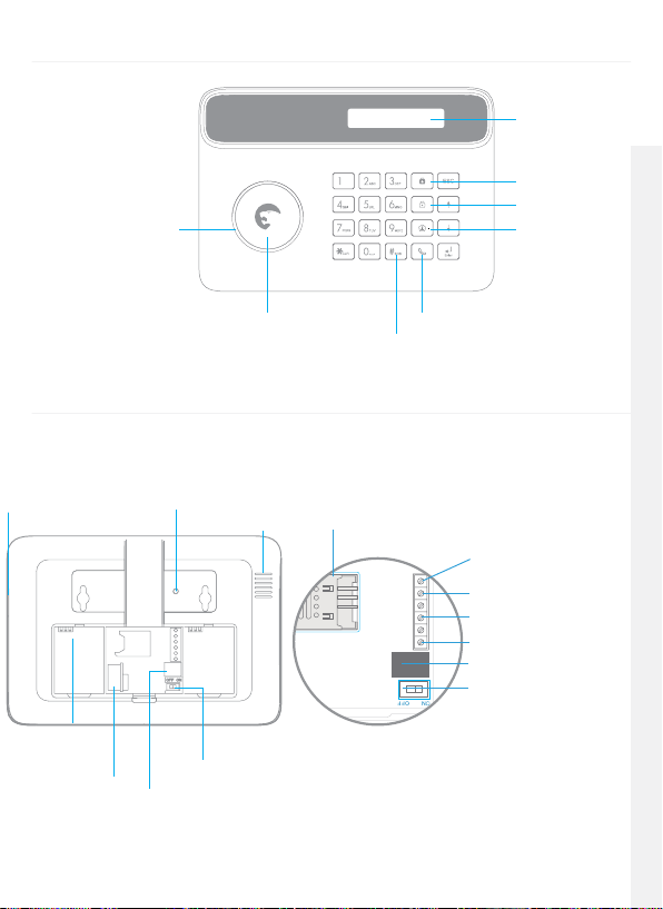
Control Panel Layout (Front)
VCC
Z1
GND
SP
GND
LOCK P1
LED Status Indicator
(armed / disarmed)
LCD Display
Arm
Disarm
Stay (Home Mode)
Control Panel Layout (Back)
Monitoring MIC
Battery
Compartment
Telephone Interface
Tamper Switch
Power Supply Interface
RFID Tag Reader
Speaker
Power Switch
SOS
SIM card Slot
Call
Output for
wired sensors
Wired sensors (24h zone)
Wired siren 500mA
Electronic lock
Adapter interface
Power On/O
Accessories Safety and TroubleshootingQuick start-up Control Panel Operations SMS Operations
4
Page 5

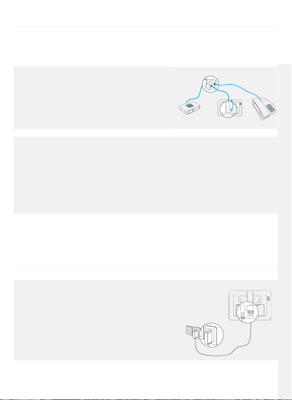
Connect your System
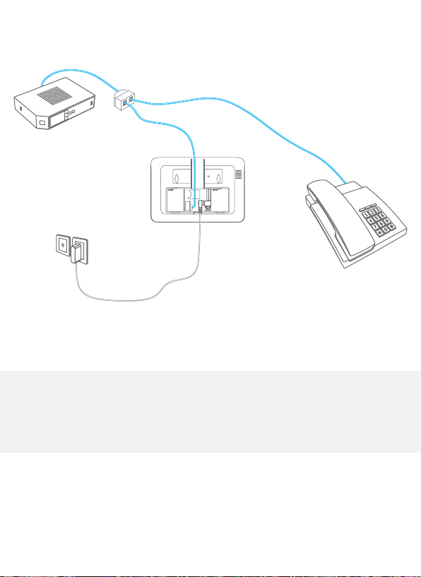
The S4 Combo Secual features a dual GSM and PSTN transmitter. This means that the control
panel of your alarm system will communicate with you either through a SIM card (GSM
module) or through your telephone landline (PSTN module).
a. Using the PSTN transmitter (telephone landline)
Connect the smaller connector of the telephone cable
(supplied with your system) to the landline interface
in the battery compartment at the back of the panel.
Connect the other end of the telephone cable to the
signal output provided by your landline carrier or to the
phone connector of your ADSL box.
b. Using the GSM transmitter (SIM card)
Open the battery compartment at the back of the control panel and insert a SIM card in the
control panel.
Important
Before using the S4 Combo Secual in GSM mode, you need to purchase a SIM card that works
on the GSM network with 850 / 900 / 1800 / 1900 MHz frequency. We recommend you to
subscribe to a plan with unlimited texts and one hour of voice. For more information, please
contact your local reseller.
Important
Make sure the SIM card does not require any PIN code. For more information, please contact
your local reseller.
Turning your System On
1. Plug the AC adaptor to an AC socket.
2. Plug the output connector of the AC adaptor into the
adaptor interface in the battery compartment at the
back of the control panel.
3. Turn the power switch to "ON" (in the battery
compartment at the back of the control panel).
Accessories Safety and TroubleshootingQuick start-up Control Panel Operations SMS Operations
5
Page 6

Mount the Control Panel
Before mounting the control panel on the wall, make sure the reception of the GSM signal is sucient.
Fix the wall-mounting bracket on the wall with screws. Wedge the panel on the bracket, make
sure they t well.
First Operations
Select GSM / PSTN Mode
Refer to the instructions page 11 to deactivate the mode you do not want to use.
GSM mode only (SIM card required, sold separately): set "LINECUT ALARM" to "OFF"
PSTN mode only (connection to your telephone landline required): set "GSM FAIL TIP" to "OFF"
By default, both GSM and PSTN are activated.
Store a phone number
To interact with the control panel by SMS, by phone call and/or from the app, at least one phone
number must be stored in the control panel. Please refer to the instructions on page 10 of this
manual.
Change the language
By default the language of the S4 control panel is set to English. If you wish to change the
system language, refer to the instructions on page 22 of this manual. "System language"
refers to the language of the SMS you receive from the control panel, and the menu of the
LCD display.
Arm / Disarm the System
The alarm system can be armed or disarmed on the control panel, by SMS, by App and by phone call.
On the control panel: Refer to the instructions on page 9 of this manual.
By RFID tag (disarm only): swipe the RFID tag in front of the RFID reader of the control panel.
To start receiving SMS notications when the system is disarmed by RFID tag, you must store an
SMS number and rename the RFID tags as explained respectively on page 18 and page 19 of
this manual (up to 4 RFID tags can be renamed). If you have stored several SMS numbers, only the
rst number stored will receive SMS notications when your system is disarmed by RFID tag.
By SMS (in GSM mode only):
To arm the system: send “1” by SMS to the number of the SIM card in the control panel.
To disarm the system: send “0” by SMS to the number of your system’s SIM card.
By app (in GSM mode only): Click on “Arm” in the app. The app is available for download on the
App Store and Google Play (more information on etiger.com).
Accessories Safety and TroubleshootingQuick start-up Control Panel Operations SMS Operations
6
Page 7

Register Wireless Accessories & RFID Tags
1. Type your admin code followed by “Enter” on the control panel to enter the setup menu.
2. Enter the Connection Mode by navigating through the menu:
"ACCESSORIES" --> "WIRELESS SENSORS" , "RFID TAG" or "REMOTE" --> "ADD A NEW"
When registering a detector, you will be asked to select the type of detector (Normal Sensor, Home
Sensor, Delay Sensor, 24 Hour Sensor). More information on page 10.
3. Trigger the accessory once within the next 15 seconds (for the RFID tag, swipe it in front of the
RFID reader of the control panel). You hear one beep: the registration is successful.
Default admin code is 123456. To change the admin code, refer to the instructions "Admin Code" on page
11.
If the accessory has already been registered, the control panel will beep twice. The rst accessory
registered is assigned to zone 1, the second accessory registered is assigned to zone 2, etc. Zones
1 to 9 can be renamed. Zones 10 to 50 cannot be renamed (refer to the instructions on page 19
to learn how to rename zones).
Speed Dial
Press the Call button “
phone number. Press the Call button “ ” to end the call.
” on the control panel for 3 seconds: the panel auto-dials the rst stored
Hands-free Phone Call from the Panel
Through PSTN
Press the Call button“
Through GSM
Press the Call button“
the Call button “
” on the control panel, type the phone number you wish to call and press “Enter”.
” on the control panel, type the phone number you wish to call and press
” again.
Accessories Safety and TroubleshootingQuick start-up Control Panel Operations SMS Operations
Hard Reset
Turn the control panel o. Press and hold the " " key while turning the control panel on. Then
enter "123456" on keyboard.
Settings will be restored to default values. Stored phone numbers and connected accessories
will be cleared.
7
Page 8

Control Panel Operations
Page 9

Arm the System
Press the Arm button " " on the control
panel. The control panel beeps once: the
system is armed.
Note
If the Entry / Exit Delay is activated, only the
Delay zone will be armed after the delay set
(refer to the instructions on page 11 of this
manual “Entry / Exit Delay”).
Disarm the System
Type your user code and press the Disarm
" on the control panel. The control
button "
panel beeps twice: the system is disarmed.
Default user code: 1234
Home Mode
Press the Stay button " " on the control
panel. The control panel beeps once: the
system is armed in Home Mode.
All the sensors assigned to the Normal zone
are armed. The sensors assigned to the
Home zone are disarmed.
For more information on zone setup, please
refer to the instructions on page 14 of this
manual.
Emergency Mode
Hold the “#
alarm is triggered immediately and the
siren rings out. At the same time, the control
panel dials the stored phone numbers.
” button for 3 seconds. The
SOS
Setup from the Control Panel
The control panel of your alarm system
features an LCD display that enables you to
navigate through the menu of the control
panel and set up your alarm system.
To enter the setting menu, type [your admin
code + Enter] on the control panel.
Default admin code: 123456
In the table on the next page, each column
represents a menu or a sub menu. Each
menu or submenu will be displayed on one
of the two lines of the LCD display. On the
LCD display, the current menu, submenu, or
setting is shown on the line at the bottom,
while the previous menu or submenu is
shown on the line at the top.
Navigate and select the setting you wish
to modify with the keys “ ” or “ ”, and enter
each menu or sub menu by pressing “Enter”.
How to use the keyboard
“ “ = delete
” = move forward
“
“ ” = move backward
“Enter” = select / conrm
“Esc” = back / previous step in the menu /
cancel
The tables on the next pages summarize
all the settings that can be accessed and
modied on the control panel.
Accessories Safety and TroubleshootingQuick start-up Control Panel Operations SMS Operations
99
Page 10

Main Menu Sub Menu 1 Sub Menu 2 Sub Menu 3 Comments Note
PHONE 1~5 IS:
PHONE NUMBERS
ACCESSORIES
ACCESSORIES RFID TAG
ACCESSORIES
ACCESSORIES TEST MODE
SMS NUM 1~5 IS:
CMS NUM 1~2 IS:
REMOTE
(or Keypad)
WIRELESS
SENSORS
ADD A NEW
DELETE ALL? 1=YES 0=NO
DELETE ONE ENTER 0130: Select the remote control you wish to delete.
ADD A NEW PLS CONNECT
DELETE ALL? 1=YES 0=NO
DELETE ONE ENTER 0150 Select the RFID tag you wish to delete
ADD A NEW
DELETE ALL? 1=YES 0=NO
DELETE ONE ENTER 0150:
NORMAL SENSOR
HOME SENSOR
DELAY SENSOR
24 HOUR SENSOR
Select the phone or SMS number you want to edit, type in the phone
number and conrm with the key "Enter". Use the key "
5 phone numbers, 5 SMS numbers and 2 CMS numbers can be
stored in the control panel.
The LCD screen displays “PLS CONNECT 30”: press any button on
the remote control within the next 30 seconds (the countdown is
indicated on the screen after "PLS CONNECT", in seconds). You hear
one beep, the LCD screen displays “ADD OK! REMOTE [01~30]”: the
connection is successful.
The LCD screen displays “PLS CONNECT 30”: swipe the RFID tag
in front of the RFID reader on the control panel within the next
30 seconds (the countdown is indicated on the screen after "PLS
CONNECT", in seconds). You hear one beep, the LCD screen displays
“ADD OK! RFID [01~50]”, the connection is successful
Select the sensor type you wish your sensor to be assigned to
(Normal Sensor, 24 Hour Sensor, Delay Sensor, or Home Sensor),
press “Enter” to conrm.
The LCD screen displays “PLS CONNECT 30”: trigger the detector
once within the next 30 seconds (the countdown is indicated on
the screen after "PLS CONNECT", in seconds). You hear one beep, the
LCD screen displays “ADD OK! SENSOR 01~50”, the connection is
successful.
Trigger the sensors you have previously connected to the control
panel. You hear 1 beep, the LCD screen displays the signals that have
been respectively sent by each sensor triggered. Make sure all the
sensors you have triggered are mentioned on the LCD screen. Press
“Esc” to exit the test mode.
" to clear.
If you want to set a CMS center phone
number, please refer to the instructions
on page 14 of this manual.
For more information on zone setup,
refer to the instructions on page 14.
This mode enables you to test if the sensors have been connected successfully
to the control panel.
Accessories Safety and TroubleshootingQuick start-up Control Panel Operations SMS Operations
10
Page 11

Main Menu Sub Menu 1 Sub Menu 2 Sub Menu 3 Comments Note
SYSTEM SETTINGS DATE AND TIME YYYYMMDD TIME e.g. 20140620 14H30
ENTRY DELAY 000300
SYSTEM SETTINGS ENTRY EXIT DELAY
EXIT DELAY 000300
AUTO ARM TIME <00:00>
SYSTEM SETTINGS AUTO ARM / DISARM
SYSTEM SETTINGS CONTROL BY PHONE ON / OFF
SYSTEM SETTINGS LINECUT ALARM ON / OFF
SYSTEM SETTINGS GSM FAIL TIP ON / OFF Notication of SIM/ GSM signal problem.
SYSTEM SETTINGS KEYPAD TONES ON / OFF
SYSTEM SETTINGS ACCESS CODE
AUTO DISARM TIME <00:00>
ON OR OFF?
ADMIN CODE 123456
USER CODE 1234
DURESS CODE 0000
OPEN DOOR CODE 8888
This function can be used if you do not want to bring a remote
control or RFID tag with you. When the system is armed, you hear
one beep every second to remind you to leave. The beep rhythm
speeds up during the last 10 seconds. If an intruder is detected, the
alarm will be delayed accordingly.
Time is calculated in seconds. The Entry and Exit Delay can be set
from 0 to 300 seconds.
You can set up the system to arm and disarm automatically at a
dened time every day.
You can activate or deactivate the control of your system by phone
call. Activating the control by phone call enables you to arm and
disarm the system and monitor your home by phone call.
If the linecut alarm is on, the alarm will be triggered if your
telephone line is down. The rst SMS number stored receives a
notication by SMS (only in GSM mode).
Activate or deactivate the sound when typing on the keyboard of
the control panel.
Your admin code enables you to enter the setup menu.
Default admin code: 123456
Your user code enables you to disarm the system on the control
panel. The user code is the access code requested when you call
the control panel.
Default user code: 1234
In case of emergency, when you are requested to disarm the system by force, it is recommended to disarm your system with your
Duress Code. The panel will silently dial the stored phone numbers.
Default duress code: 0000
You can open electronic doors using this code. The door must be
wired to the [LOCK] interface on the back of the control panel.
The entry and exit delay is only for sensors
connected as Delay Zone accessories (see
"Wireless" on page 10).
The Entry Delay gives you time to disarm
the system on the control panel without
triggering an alarm.
The Exit Delay gives you time to arm the
system on the control panel and leave
your home without triggering an alarm.
Setting Auto Arm and Auto Disarm to
the exact same time will deactivate the
function.
See instructions on page 13 for more
information on the control of the system
by phone call.
Deactivate this function if you want
to use the alarm system in GSM mode
only.
Deactivate this function if you want to
use the alarm system in PSTN mode only.
It is recommended to change all codes
before using your system for the rst
time and to keep your codes secret
Accessories Safety and TroubleshootingQuick start-up Control Panel Operations SMS Operations
11
Page 12

Main Menu Sub Menu 1 Sub Menu 2 Sub Menu 3 Comments Note
SYSTEM SETTINGS RINGING TIMES <09>
SIREN SWITCH
WIRED SIREN
IN SIREN VOLUME 01 0=MUTE
SIREN ALERT TIME 3 MIN
SYSTEM SETTINGS SIREN SETUP
BUILTIN SIREN
WIRELESS SIREN
SYSTEM SETTINGS USER ID 4 DIGITS :0000 More information on page 14 of this manual
SYSTEM SETTINGS
SYSTEM SETTINGS CALL RECYCLE <09>
SYSTEM SETTINGS BACKLIGHT TIME 030 S Press “Enter ” to adjust the time during which the LCD screen is lit. Backlight time can be set from 0 to 300 s
SYSTEM SETTINGS LANGUAGE Change the language of the system.
SYSTEM SETTINGS RESET
SYSTEM SETTINGS ABOUT ABOUT JUN 4 2014
HISTORY - - - Choose the event log you need to track, press “Enter”.
ARM UPLOAD ON / OFF If "ON", you receive a notication by SMS when the system is armed.
DISARM UPLOAD ON / OFF If "ON", you receive a notication by SMS when the system is disarmed.
<ON OR OFF?>
ARM/DISARM TONE
<ON OR OFF?>
SIREN SWITCH
<ON OR OFF?>
ARM/DISARM TONE
<ON OR OFF?>
SIREN SWITCH
<ON OR OFF?>
ARM/DISARM TONE
<ON OR OFF?>
This function enables you to determine the number of times the control
panel will ring before taking your call (for control by phone call).
Siren ringing time is calculated in minutes, default setting is 3
minutes. If you set the ringing time to 0, the siren will not ring out.
When the alarm is triggered, the control panel dials the numbers
you have stored. If you do not disarm the system, the control
panel will call you again (up to 9 times). The “Call Recycle” function
enables you to dene the number of times the control panel
attempts to call you.
All system settings will be restored to default setting.
Stored phone numbers and connected accessories will be cleared.
Wired siren refers to a siren connected
to the control panel by wire.
Built-in siren refers to the siren featured
in the control panel.
Wireless siren refers to a siren
connected to the control panel by
radio-frequency.
This information is supplied by your CMS
center. After having stored the user ID, the
CMS center will be able to determine your
exact location according to your ID number.
This function is only available in GSM
mode (SIM card required).
Languages available may vary depending
on the version of your product.
The control panel keeps in record the
latest 150 event logs.
Accessories Safety and TroubleshootingQuick start-up Control Panel Operations SMS Operations
12
Page 13

Control by Phone Call
This feature is available only after having enabled it from the control panel, as explained on page
11 of this manual.
Method 1
When an alarm has been triggered, the control panel dials the stored phone numbers. When
you pick up the phone, follow the voice instructions to control the panel from distance (refer
to the instructions in the table below).
Method 2
1. Dial the telephone number of your control panel (either the number of the SIM card in your
control panel or the number of the landline to which your panel is connected). After getting
through, the voice instructions will guide you to enter your access code.
2. Enter your access code (user code), followed by ”#”.
3. A voice gives you the options you can select.
4. Select the operations to control the panel (see instructions in the table below).
Note
The call will end automatically if you do not send any command within 30 seconds.
Table of commands for control by phone call
Command Function Comment
Press “1“ Arms the system Voice prompt “System armed”
- Disarms the system and turns the
Press “0“
Press “
Press “3“ Phone call with control panel -
Press “6“ Turns the siren o -
Press “9“ Turns the siren on -
Press “#“
Note
In GSM mode, the audio monitoring is not limited in time.
In PSTN mode (connected to your landline), the audio monitoring is limited to 80 seconds. If
you wish to extend the time of audio monitoring, press the “
of the 80 seconds.
siren o
- Stops monitoring without hanging up
- Ends the phone call without hanging
up
“ Audio monitoring Press “ ” to extend the monitoring time
- Disarms the system and turns the
siren o
- Exits control by phone call
Voice prompt “System disarmed”
Hanging up also exits the control by
phone call.
” on your phone before the end
Accessories Safety and TroubleshootingQuick start-up Control Panel Operations SMS Operations
13
Page 14

Zone Setup of Accessories
Every detector can be assigned to 4 dierent categories of zones: Home Zone, Delay Zone,
Normal Zone and 24-H Zone. To assign a detector to a zone, follow the instructions on page
10 of this manual (the zone will be assigned at the time of connection of the accessory).
Normal zone
When the system is armed, if a sensor is triggered, the siren rings out. When the system is
disarmed, sensors do not trigger an alarm.
24h zone
Regardless the system is armed or disarmed, sensors assigned to the 24h zone can trigger an
alarm. It is recommended to assign smoke detectors, gas detectors and outdoor beam sensors to
the 24-H zone.
Delay zone
If you want to set up the entry and exit delay functions, corresponding sensors must be
assigned to the Delay zone. Once the delay time has been set up, the sensors will not trigger
the alarm during the delay set. Refer to the instructions “Entry and Exit Delay” on page 11 of
this manual. It is recommended to assign the Door / Window Contact to the Delay zone.
Home zone
When the system is armed in Home Mode, the sensors assigned to the Home zone do not
trigger an alarm. It is recommend to assign motion dectors to the Home zone so that you can
have your system armed in Home Mode when you are home and move inside your home without
triggering any alarm.
Connect to CMS Center
Ignore this step if you are not connected to a CMS center. I f you are connected to a CMS center,
the control panel will upload your contact ID to the CMS center automatically if an intrusion
is detected.
Accessories Safety and TroubleshootingQuick start-up Control Panel Operations SMS Operations
14
Page 15

...
SMS Operations
Page 16

SMS Operations
IMPORTANT: BEFORE USING FOR THE FIRST TIME
INSERT A SIM CARD IN THE CONTROL PANEL BEFORE STARTING SMS OPERATIONS.
MAKE SURE THE SIM CARD DOES NOT REQUIRE ANY PIN CODE.
SAVE A SMS NUMBER IN THE CONTROL PANEL USING THE CONTROL PANEL.
Only stored numbers can control and congure the system.
Refer to the instructions page 10)
Each SMS operation dened in this user manual will be illustrated as follows:
You send:
SMS Command
The control panel replies:
Control panel’s reply
The system is in English by default. To change the system language, refer to the
instructions on page 22 of this manual.
Important
When replying to the control panel by SMS, make sure no space follows punctuation marks
like "." or ":". For examples, to store SMS numbers, your SMS must be formatted as follows:
The rst blue speech bubble is the SMS
command sent by the user.
The rst grey speech bubble is the reply sent
by the control panel.
The speech bubbles that follow are the
dialogue between the user and the control
panel (SMS sent by the user are in blue, SMS
sent by the control panel are in grey).
Accessories Safety and TroubleshootingQuick start-up Control Panel Operations SMS Operations
SMS numbers:
1.067890033
2.067890022
3.067890011
4.067890000
5.
No space after "1."
16
Page 17

Disarm the System
Settings Enquiry
Send:
0
System disarmed.
Arm the System
Send:
1
System armed.
Home Mode
Send:
2
Send:
00
System:Disarmed
AC power:on
Note
The values indicated hereinabove will
change after having set up the system.
Accessories Safety and TroubleshootingQuick start-up Control Panel Operations SMS Operations
System in home mode.
17
Page 18

Store Phone Numbers
Send:
5
Phone numbers:
1.
2.
3.
4.
5.
Copy, paste, then edit
(case sensitive):
Phone numbers:
1. 067890033
2. 067890022
3. 067890011
4. 067890000
5.
Store Phone Numbers for SMS
Notications
Send:
6
SMS numbers:
1.
2.
3.
4.
5.
Copy, paste, then edit
(case sensitive):
SMS numbers:
1. 067890033
2. 067890022
3. 067890011
4. 067890000
5.
Accessories Safety and TroubleshootingQuick start-up Control Panel Operations SMS Operations
Ok
Ok
Note
The rst SMS number will receive SMS
notications when the system is disarmed
by RFID tag. To start receiving these
notications, you must rename the RFID
tags. Up to 4 RFID tags can be renamed.
Other tags will be attributed a number
based on the order of registration to the
control panel. Refer to the instructions on
page 10 to learn how to register an RFID
tag in the control panel.
18
Page 19

Rename Zones
Send "91~99". For example for zone 1, send:
91
SMS Alert for Accessory Low Battery
(available for two-way acessories such as
Motion Detectors)
For accessories assigned to zones that have
been renamed, an SMS will be sent under
the format “Zone name + low battery”.
Zones names:
1.
Copy, paste, then edit
(case sensitive):
Zones names:
1.Entrance door sensor
Ok
Note
Zones 1 to 9 can be renamed. The name of
the zone cannot consist of more than 30
Latin characters. Zones 10 to 50 cannot be
renamed.
Bedroom PIR low battery
For accessories assigned to zones that
have not been renamed, an SMS will be
sent under the format “Zone number + low
battery”.
Zone 10 low battery.
SMS Alert for Accessory Tamper
Alarm
(available for two-way acessories such as
Motion Detectors)
For accessories assigned to zones that have
been renamed, an SMS will be sent under
the format “Zone name + tamper alarm”.
Bedroom PIR tamper alarm.
For accessories assigned to zones that have
not been renamed, an SMS will be sent
under the format “Zone number + tamper
alarm”.
Zone 10 tamper alarm.
Accessories Safety and TroubleshootingQuick start-up Control Panel Operations SMS Operations
19
Page 20

Rename RFID Tag
Entry and Exit Delay Time
Send:
10
Rename RFID tags:
1.
2.
3.
4.
Copy, paste, then edit
(case sensitive):
Rename RFID tags:
1. Tom
2. Nurse
3. Nancy
4. David
Ok
Note
The rst SMS number will receive SMS
notications when the system is disarmed
by RFID tag. To start receiving these
notications, you must rename the RFID
tags. Up to 4 RFID tags can be renamed.
Other tags will be attributed a number
based on the order of registration to the
control panel. Refer to the instructions on
page 10 to learn how to register an RFID
tag in the control panel.
Send:
11
Entry delay time(0-300sec):0
Exit delay time(0-300sec):0
Copy, paste, then edit
(case sensitive):
Entry delay time(0-300sec):10
Exit delay time(0-300sec):20
Ok
Note
This function will only aect detectors
assigned to the Delay zone. Refer to the
instructions on "Wireless" on page 10 of this
manual to learn how to set up your sensor to
the Delay zone.
This function can be used if you do not want to
bring a remote control or a RFID tag with you.
When you arm the system, the system
will be armed after the delay set. When
you disarm the system, the system will be
disarmed after the delay set.
When arming the system, you hear one
beep every second to remind you to leave.
The beep rhythm speeds up during the last
10 seconds. If an intruder is detected, the
alarm will be delayed accordingly.
Accessories Safety and TroubleshootingQuick start-up Control Panel Operations SMS Operations
20
Page 21

Siren Volume and Ringing Time
Disarm Password
Send:
12
Siren volume(0=Mute,1=High):1
Siren ringing time(1-9min):5
Copy, paste, then edit
(case sensitive):
Siren volume(0=Mute,1=High):0
Siren ringing time(1-9min):1
Ok
Send:
13
Disarm password (4 digits):
1234
Copy, paste, then edit
(case sensitive):
Disarm password (4 digits):
8888
Ok
Accessories Safety and TroubleshootingQuick start-up Control Panel Operations SMS Operations
21
Page 22

Change System Language
Send the code corresponding to the
language you want to set. For example, for
English, send “0001”.
0001
Restore System to Factory
Settings by SMS
Send:
0000
Ok
Refer to the table below for the full list of
languages:
0001 English
0002 French
0003 Russian
0004 Danish
0005 Dutch
0006 Italian
0007 Swedish
Languages available may vary depending
on the version of your product.
0008 German
0009 Spanish
0010 Finnish
0011 Norwegian
0012 Arabic
0013 Farsi
Ok
The settings will be restored to default
values. Stored phone numbers and
connected accessories will not be deleted.
Note
Only stored numbers can send the SMS to
restore factory settings.
Accessories Safety and TroubleshootingQuick start-up Control Panel Operations SMS Operations
22
Page 23

Accessories
Page 24

Wireless Remote Control
Disarm
LED indicator
Arm
Arm the system
Press the Arm button " " to arm the alarm
system. The LED indicator lights up (the
control panel beeps once). The system is
armed.
If an intruder is detected, the siren rings
out. (The siren turns o after 5 minutes as
per default settings.) In the meantime, the
system dials the stored phone numbers
automatically.
Disarm the system
Press the Disarm button " " to disarm the
alarm system. The LED indicator turns o
(the control panel beeps twice). The system
is disarmed.
Home Mode
Press the Home Mode button " " on the
remote control. The system state LED is on.
All the sensors in regular zones are armed
except those in the Home Mode zone.
The sensors in the Home Mode zone are
disarmed so that users can move inside
their home.
SOS
Home Mode
Accessories Safety and TroubleshootingQuick start-up Control Panel Operations SMS Operations
24
Page 25

Mute Mode
Press the Home Mode button " " and
then the Arm "
immediately after. Doing so, the control
panel does not beep when you arm or
disarm your system.
" or Disarm " " button
Emergency Mode
Regardless the status of the system, the alarm
is triggered when the SOS button "SOS" is
pressed on the remote control.
At the same time, the control panel sends a
notication by SMS ("RC-01 SOS", 01 being
the remote control's number) and dials the
pre-stored phone numbers.
Register in the control panel
Refer to the instructions in the table on page 10 of this manual "REMOTE".
To check if the registration is complete, refer to the instructions in the table on page 10
(“Test Mode”).
Specications
Power supply
DC 3V (CR2025 button battery x1)
Static current
≤10 uA
Operating current
≤7 mA
Transmission distance
≤ 80 m (in open area)
Radio-frequency:
433MHz (±75KHz)
Housing material
ABS plastic
Operating conditions
Temperature: -10°C ~ +55°C
Relative Humidity: ≤80%
(non-condensing)
Dimensions
57 x 31 x 11 mm
Accessories Safety and TroubleshootingQuick start-up Control Panel Operations SMS Operations
25
Page 26

Wireless Motion Detector
Features
The ES-D1A is a high performance wireless motion detector boasting a digital dual-core fuzzy
logic infrared control chip with intelligent analysis. This technology identies interferences
created by body motion and reduces the false alarm rate.
With automatic temperature compensation and anti-air turbulence technology, it easily
adapts to environmental changes.
Design
1. LED indicator
2. Detection window
3. Bracket
1
2
PCB Layout
LED working
indicator
Antenna
3
*Tamper switch
When the alarm system is armed, the tamper
switch will trigger the alarm if the case is
opened.
**Infrared sensor
Detects the infrared rays released by human
body motion. Do not touch the surface. Keep
the surface clean.
Alarm zone
setup
Tamper
switch*
Infrared
sensor**
AA 1.5V LR6
LED indications
Blinks continuously: self-testing
Blinks once: an intruder is detected
Blinks twice: self-testing is complete; entering working mode.
Blinks once every 3 seconds: under-voltage indication, the batteries must be replaced. (You
will be informed by SMS when the batteries are low if the motion detector is registered in the
control panel.)
Accessories Safety and TroubleshootingQuick start-up Control Panel Operations SMS Operations
26
Page 27

Usage
Open the case and remove the battery activation
strip. Self-testing will start for 30 seconds.
When the sensor is in operation, if it is triggered
more than twice within 3 minutes, it will switch
to standby mode to save power. If no movement
is detected within the next 3 minutes, the sensor
goes back to working mode.
Connect Button
Register in the control panel
Navigate through the menu of the control panel and reach "ADD A NEW" (Wireless Sensor).
Press the Connect button at the back of the motion sensor or trigger the sensor (by moving in
front of it) to register the detector in the control panel.
To check if the registration is complete, refer to the instructions in the table on page 10
"TEST MODE".
Installation
Avoid mounting the detector close to windows, air conditioner, heater, refrigerator, oven,
sunshine and places where the temperature changes fast or where the air stream ows
frequently.
If two detectors are installed in the same detection scope, adjust the location to avoid
interferences and false alarms.
Fix the bracket on the wall with screws
and attach the detector to the bracket.
Adjust the bracket to change the
detection distance and angle. It is
recommended to mount the detector
2.2 m from the ground.
The detector is more sensitive to
cross movements than vertical
movements.
2.2 m
Ground
Top view
Side view
Top
Boom
Accessories Safety and TroubleshootingQuick start-up Control Panel Operations SMS Operations
27
Page 28

Testing
A. After the installation, turn the detector on. After one minute of self-testing, press the test
button, walk in the scope of detection and watch the LED indicator to make sure the detector
is working.
B. The LED indicator blinks once when body movement is detected.
C. Adjust the detector angle to achieve the best detection performance.
Specications
Power supply
DC 3V (AA 1.5V LR6 Batteries x 2)
Static current
≤ 30uA
Alarm current
≤ 15 mA
Detection scope
8m / 110°
Transmission distance
≤ 80m (in open area)
Radio-frequency
433 MHz (±75 KHz)
Housing material
ABS plastic
Operating conditions
Temparature: -10°C~55°C
Relative humidity: ≤ 80% (non-condensing)
Detector dimensions (L x W x H)
107 x 53 x 32 mm
Bracket dimensions (L x W x H)
52 x 30 x 26.5 mm
Detection Scope
110°
Top view
0m 2m 4m 6m 8m
2m
0m
Side view
Accessories Safety and TroubleshootingQuick start-up Control Panel Operations SMS Operations
28
Page 29

Wireless Door / Window Contact
Features
The ES-D3A/B/C is a Door / Window Contact that can be installed on doors, windows, and any
other objects that open and close. The sensor sends a signal to the control panel when the
magnet is separated from the transmitter.
Thanks to the tamper switch, any attempt to remove the cover of the Door / Window Contact
will trigger the alarm.
Design
Magnet
Transmitter
LED indicator
LED indications
Blinks once: the door or window is open
and the transmitter sends a signal to the
control panel.
Blinks quickly: Low power indication, the
batteries must be replaced.
PCB Layout (ES-D3A/ES-D3B)
Tamper switch
A23 12V battery
Zone setting
LED working indicator
PCB Layout (ES-D3C)
Tamper switch
Jumpers for zone
setup
AAA 1.5V battery
LED indicator
Register in the control panel
Navigate through the menu of the control panel and reach "ADD A NEW" (Wireless Sensor).
Then separate the magnet from the transmitter to register the detector in the control panel.
To check if the registration is complete, arm the system and separate the magnet from the
transmitter again by opening the door or window on which it is installed. If the siren rings
out, the registration is successful. Or refer to the instructions in the table on page 10 "TEST
MODE".
Accessories Safety and TroubleshootingQuick start-up Control Panel Operations SMS Operations
29
Page 30

Installation
- Open the case and remove the battery activation strip.
- Mount the sensor on the door and the magnet on the
door frame.
- Make sure the magnet is placed above the transmitter.
- Mount the magnet max. 1 cm away from the transmitter
and secure the transmitter and magnet with doublesided tape or screws.
- Avoid mounting the sensor in areas with a large amount
of metal or electrical wiring such as a furnace or utility
room.
Specications (ES-D3A/ES-D3B)
Power supply
DC 12V (A23 12V Battery x 1)
Static current
≤ 30 uA
Alarm current
≤ 15 mA
Transmitting distance
≤80 m (in open area)
Radio-frequency
433 MHz (±75 KHz)
Housing material
ABS plastic
Operating conditions
Temparature: -10°C~55°C
Relative humidity: ≤ 80% (non-condensing)
Transmitter dimensions (LxWxH)
60 x 45 x 18 mm
Magnet dimensions (LxWxH)
45 x 19 x 17.5 mm
Specications (ES-D3C)
Power supply
AAA 1.5 V Battery x1
Static current
≤ 30 uA
Alarm current
≤ 15 mA
Transmitting distance
≤80 m (in open area)
Radio-frequency
433 MHz (±75 KHz)
Housing material
ABS plastic
Operating conditions
Temparature: -10°C~55°C
Relative humidity: ≤ 80% (non-condensing)
Transmitter dimensions (LxWxH)
60 x 45 x 18 mm
Magnet dimensions (LxWxH)
45 x 19 x 17.5 mm
Accessories Safety and TroubleshootingQuick start-up Control Panel Operations SMS Operations
30
Page 31

RFID Tag
Features
The RFID tag enables you to disarm your system or unlock electronic door locks.
Register in the control panel
Refer to the instructions in the table page 10 of this manual (“RFID TAG”).
Specications
Dimensions
45 x 30 x 7 mm
Register an Additional eTiger Siren
The control panel of the S4 features a built-in 100 dB siren.
Your eTiger security systems supports additional indoor and/or outdoor sirens so to enable
you to extend your system according to your needs.
To register an additional eTiger siren, refer to the instructions provided in the manual that
comes with your siren.
For more information on sirens and accessories compatible with eTiger security systems, visit
our website etiger.com
Accessories Safety and TroubleshootingQuick start-up Control Panel Operations SMS Operations
31
Page 32
Troubleshooting and Safety Instructions
Page 33
FAQ
Issue Cause of malfunction Solution
The control panel is switched oOpen the battery compartment
No response following
interaction with the
control panel
Accessories cannot
connect to the control
panel
No response from the
control panel following
commands from the
remote control
RFID tag fails to disarm
the system
Impossible to access
settings from the
control panel
If you are experiencing issues that are not described in the FAQ above, visit etiger.com to
download the latest update of this user manual and for additional support.
Electricity grid failure Contact your electricity provider
Backup batteries are empty
The control panel is not in
Connection mode
Accessories have not been
triggered for connection
When attempting the
connection, the control panel
beeps twice
The remote control has
not been connected to the
control panel
Remote control is too far from
the control panel
RFID tag has not been
connected to the control
panel
You are not in the setup menu
of the LCD display
and turn the power on
Plug the AC adapter to an AC
socket
Make sure the control panel is in
Connexion mode
Make sure the accessory is
triggered so to send a signal to the
control panel
The accessory has already been
connected
Make sure you do not trigger any
other accessory when connecting
one accessory to the control panel
(e.g. do not stay in the detection
scope of a motion detector if it is
not the one you want to connect)
Follow the instructions in this
manual to connect the remote
control to the panel
Transmission distance of the
remote control: 80 m (in open area)
A signal repeater can be installed
to increase the transmission
distance
Follow the instructions in this
manual to connect the RFID tag to
the control panel
Enter your admin code followed by
“Enter“ to enter the setup menu
Accessories Safety and TroubleshootingQuick start-up Control Panel Operations SMS Operations
33
Page 34

Precautions
For a safer use of the product and to optimize the lifespan of the product, we recommend you
to follow the precautions below:
- The wireless accessories must be connected to the control panel.
- Low power voltage may aect transmission distance.
- Do not press the SOS key on the remote control if it is unnecessary to avoid disturbing
neighborhood.
- Check the system regularly to make sure the system works properly.
- The control panel is neither waterproof nor moisture-proof, install it in a shady, cool and dry
place.
- The case of the control panel is made of ABS plastic. Keep away from bright light for a longer
lifespan.
- The control panel is not explosion-proof. Keep away from re and ames.
- Install the control panel away from objects such as heater, air conditioner, microwave oven etc.
that generate heat or electromagnetic elds.
- Dispose of the batteries according to local regulations.
- Dismantling of this product must be done by professional personnel only.
Accessories Safety and TroubleshootingQuick start-up Control Panel Operations SMS Operations
34
Page 35
Standards
This product bears the selective sorting symbol for waste electrical and electronic equipment
(WEEE). This means that this product must be handled pursuant to European Directive
2002/96/EC in order to be recycled or dismantled to minimize its impact on the environment.
For further information, please contact your local or regional authorities.
Electronic products not included in the selective sorting process are potentially dangerous for
the environment and human health due to the presence of hazardous substances.
In compliance with European laws. This product is in compliance with the essential
requirements and other relevant provisions of Directive 1999/5/EC.
This product was designed and manufactured in compliance with Directive 2002/95/EC of
the European Parliament and of the Council on the restriction of use of certain hazardous
substances in electrical and electronic equipment (RoHS Directive - RoHS) and is deemed to
comply with the maximum concentration values set by the European Technical Adaptation
Committee (TAC).
Manufactured in China.
Images, illustrations and text are non-contractual. ETIGER and the ETIGER logo are registered
trademarks and the property of ETIGER. Copyright © 2015 ETIGER. All rights reserved.
Accessories Safety and TroubleshootingQuick start-up Control Panel Operations SMS Operations
S4-C-UM-EN20150812-1.5-W
Rue de la Loi, 25, 7100 La Louvière, Belgium
ETIGER EUROPE
35
Page 36

www.etiger.com
Page 37
S4 Combo Secual / S4 Combo Vid Secual
GSM- und Festnetz-Alarmsystem
www.etiger.com
DE
Page 38

Merkmale
- GSM-/PSTN-Sender
- Unterstützt bis zu 30 Fernbedienungen, 50 zusätzliches Funkzubehör und 50 RFID-Tags
- Speicherung von bis zu 5 Telefonnummern, 5 SMS-Nummern und 2 CMS-Nummern (für Systeme mit
CMS)
- Aktivierung/Deaktivierung des Systems per SMS, Telefonanruf oder App (mit iOS oder Android)
- Kann per RFID-Tag deaktiviert werden
- Integrierte Sirene (100 dB) und Anruunktion vom Bedienfeld aus
- SMS-Benachrichtigungen bei Stromverlust, Stromwiederherstellung und schwacher Batterie
- Audioüberwachung des Standorts aus der Distanz
- 2 x 800 mAh Lithium-Batterien im Lieferumfang enthalten (8 Stunden Batterielebensdauer im Standby-
Modus)
Technische Daten
Produktname
S4 Combo Secual
Artikelnummer
S4-C
Stromversorgung des Bedienfelds
Eingangsspannung: AC 110-240 V / 50-60 Hz
Ausgangsleistung: DC 12 V / 800 mA
GSM-Betriebsfrequenz
850 / 900 / 1800 / 1900 mHz
Radiofrequenz
433 MHz (±75 KHz)
Ruhestrom
110 ma
Verpackungsinhalt
S4 Bedienfeld x1
Bewegungsmelder x2
Tür-/Fensterkontakte x2
Fernbedienungen x2
RFID-Tags x2
PSTN-Kabel x1
PSTN-Adapter x1
Alarmstrom
340mA
Backup-Batterien:
Lithium-Batterien: 3,7V / 800 mAh x 2 (BL-5B)
Interne Sirene
100 dB
Gehäusematerial
ABS-Kunststo
Betriebsbedingungen
Umgebungstemperatur: -10 °C~55 °C
Luftfeuchtigkeit: ≤80 % (nicht kondensierend)
Abmessungen des Bedienfelds (L x B x H)
188 x 132 x 26 mm
Stromadapter x1
Dokumentation x1
S4 Combo Vid Secual
+ IP-Kamera x 1 (mit Stromadapter und Handbuch)
Page 39
Schnellstart
Page 40
Aufbau des Bedienfelds (vorne)
VCC
Z1
GND
SP
GND
LOCK P1
LED-Statusanzeige
(aktiviert/deaktiviert)
LCD-Display
Aktivieren
Deaktivieren
Aufenthalts-/
Home-Modus
Schnellstart Arbeiten mit dem Bedienfeld Arbeiten mit SMS
Aufbau des Bedienfelds (hinten)
Überwachungsmikrofon
Batteriefach
Telefonanschluss
Sabotagekontakt
Stromschalter
Anschluss
Stromversorgung
RFID-Tag-Lesegerät
Lautsprecher
SOS
SIM-Kartenslot
Anrufen
Ausgang für
Kabelsensoren
Kabelsensoren (24 h-Zone)
Kabelsirene 500 mA
Elektronisches Schloss
Adapterschnittstelle
Power EIN/AUS
Zubehör Sicherheit und Fehlerbehebung
4
Page 41
Anschluss Ihres Systems
Das S4 Combo Secual bietet sowohl einen GSM- als auch einen PSTN-Sender. Das bedeutet, das
Bedienfeld Ihres Alarmsystems kommuniziert entweder über eine SIM-Karte (GSM-Modul) oder über
Ihre Telefonleitung (PSTN-Modul).
a. Über PSTN-Sender (Telefonleitung)
Verbinden Sie den kleinen Stecker des Telefonkabels (im
Lieferumfang enthalten) mit der Telefonschnittstelle im
Batteriefach auf der Rückseite des Bedienfelds. Verbinden Sie
das andere Ende des Telefonkabels mit dem Signalausgang
Ihres Telefonanbieters oder mit dem Telefonanschluss Ihrer
DSL-Box.
b. Über GSM-Sender (SIM-Karte)
Önen Sie das Batteriefach auf der Rückseite des Bedienfelds und stecken Sie eine SIM-Karte in das
Bedienfeld.
Wichtig
Vor der Verwendung von S4 Combo Secual im GSM-Modus muss eine SIM-Karte erworben werden, die
für ein GSM-Netzwerk mit einer Frequenz von 850 / 900 / 1800 / 1900 MHz geeignet ist. Wir empfehlen
Ihnen einen Plan mit unbegrenzt viel Textnachrichten und mit einer Stunde Sprachnachricht. Weitere
Informationen erhalten Sie von Ihrem Wiederverkäufer vor Ort.
Wichtig
Stellen Sie sicher, dass die SIM-Karte nicht durch einen PIN-Code geschützt ist. Weitere I nformationen
erhalten Sie von Ihrem Wiederverkäufer vor Ort.
Einschalten des Systems
1. Stecken Sie den Stromadapter in eine Steckdose.
2. Stecken Sie den Ausgangsstecker des Stromadapters in den
Adapteranschluss des Batteriefachs auf der Rückseite des
Bedienfelds.
3. Stellen Sie den Stromschalter auf "ON" (im Batteriefach auf
der Rückseite des Bedienfelds).
Schnellstart Arbeiten mit dem Bedienfeld Arbeiten mit SMS
Zubehör Sicherheit und Fehlerbehebung
5
Page 42

Befestigung des Bedienfelds
Überprüfen Sie vor der Befestigung des Bedienfelds an der Wand, ob das GSM-Signal an dieser Position
ausreichend stark ist.
Befestigen Sie den Wandbefestigungshalter mit Schrauben an der Wand. Klemmen Sie das Bedienfeld
in den Halter und achten Sie auf einen sicheren Halt.
Schnellstart Arbeiten mit dem Bedienfeld Arbeiten mit SMS
Erste Schritte
Auswahl des GSM-/PSTN-Modus
Anweisungen für die Deaktivierung des nicht verwendeten Modus nden Sie auf der Seite 11.
Nur GSM-Modus (SIM-Karte erforderlich, separat erhältlich): "LTGUNTERB ALARM" einstellen auf "AU S"
Nur PSTN-Modus (Verbindung mit Telefonleitung erforderlich): "GSM FEHL TIP" einstellen auf "AUS"
Standardmäßig sind GSM und PSTN aktiviert.
Speicherung einer Telefonnummer
Für die Interaktion mit dem Bedienfeld per SMS, Telefonanruf und/oder App muss im Bedienfeld
mindestens eine Telefonnummer gespeichert werden. Folgen Sie dafür den Anweisungen auf der Seite
10 dieses Handbuchs.
Änderung der Sprache
Standardmäßig ist die Sprache des S4-Bedienfelds auf Englisch eingestellt. Anweisungen für die
Änderung der Systemsprache nden Sie auf der Seite 21 dieses Handbuchs. "Systemsprache"
bezieht sich auf die Sprache der SMS, die Sie vom Bedienfeld erhalten, und auf das Menü in der LCDAnzeige.
Aktivierung/Deaktivierung des Systems
Das Alarmsystem kann über das Bedienfeld, per SMS, App oder Telefonanruf aktivier t oder deaktiviert werden.
Über das Bedienfeld: Folgen Sie dafür den Anweisungen auf der Seite 9 dieses Handbuchs.
Per RFID-Tag (nur deaktivieren): wischen Sie mit dem RFID-Tag über die Vorderseite des RFID-
Lesegeräts des Bedienfelds.
Um bei Deaktivierung des Systems per RFID-Tag SMS-Benachrichtigungen zu erhalten, müssen eine SMSNummer gespeichert und der RFID-Tag umbenannt werden, wie auf Seite 18 und Seite 19 dieses
Handbuchs erläutert (bis zu 4 RFID-Tags können umbenannt werden). Wurden mehrere SMS-Nummern
gespeichert. erhält nur die erste gespeicherte Nummer SMS-Benachrichtigungen, sobald das System per
RFID-Tag deaktiviert wird.
Per SMS (nur im GSM-Modus):
Aktivierung des Systems: senden Sie “1” per SMS an die Nummer der SIM-Karte im Bedienfeld.
Deaktivierung des Systems: senden Sie “0” per SMS an die Nummer der SIM-Karte im Bedienfeld.
Per App (nur im GSM-Modus): Klicken Sie auf “Aktivieren” in der App. Die App kann im App Store oder
über Google Play heruntergeladen werden (weitere Informationen unter etiger.com).
Zubehör Sicherheit und Fehlerbehebung
6
Page 43
Registrierung von Funkzubehör & RFID-Tags
1. Geben Sie Ihren Admin-Code ein, gefolgt von “Enter ” auf dem Bedienfeld, um in das
Einrichtungsmenü zu gelangen.
2. Wechseln Sie in den Verbindungsmodus, indem Sie durch das Menü navigieren:
"ZUBEHÖR" --> "FUNKSENSOREN" , "RFID-TAG" oder "FERNBEDIENUNG" --> "NEU"
Weitere Informationen nden Sie auf der Seite 10 dieses Handbuchs.
3. Lösen Sie das Zubehör innerhalb der nächsten 15 Sekunden einmal aus (wischen Sie mit dem RFID-
Tag über das RFID-Lesegerät des Bedienfelds). Ein Piepton wird ausgegeben: Die Registrierung war
erfolgreich.
Der Standard-Admin-Code lautet 123456. Anweisungen für die Änderung des Admin-Codes nden Sie
unte r "Admin-Code" auf Seite 11.
Wurde das Zubehör bereits registriert, wird das Bedienfeld zweimal einen Piepton ausgeben. Das
erste registrierte Zubehör wird der Zone 1 zugewiesen, das zweite registrierte Zubehör der Zone 2
usw, Die Zonen 1 bis 9 können umbenannt werden. Die Zonen 10 bis 50 können nicht umbenannt
werden (siehe Anweisungen auf Seite 19 für die Umbenennung von Zonen).
Kurzwahl
Drücken Sie die Anruftaste “
die erste gespeicherte Telefonnummer. Drücken Sie die Anruftaste “ ”, um den Anruf zu beenden.
” des Bedienfeldes für 3 Sekunden: Das Bedienfeld wählt automatisch
Handfreier Anruf vom Bedienfeld aus
Schnellstart Arbeiten mit dem Bedienfeld Arbeiten mit SMS
Per PSTN
Drücken Sie die Anruftaste“
und drücken Sie “Enter”.
Per GSM
Drücken Sie die Anruftaste“
und drücken Sie erneut die Anruftaste “
” auf dem Bedienfeld, geben Sie die gewünschte Telefonnummer ein
” auf dem Bedienfeld, geben Sie die gewünschte Telefonnummer ein
”.
Hard Reset
Schalten Sie das Bedienfeld aus. Drücken und halten Sie die Taste " ", während Sie das Bedienfeld
einschalten. Geben Sie dann "123456" mit der Tastatur ein.
Die Einstellungen werden jetzt auf die Standardwerte zurückgesetzt. Gespeicherte
Telefonnummern und verbundenes Zubehör werden gelöscht.
Zubehör Sicherheit und Fehlerbehebung
7
Page 44
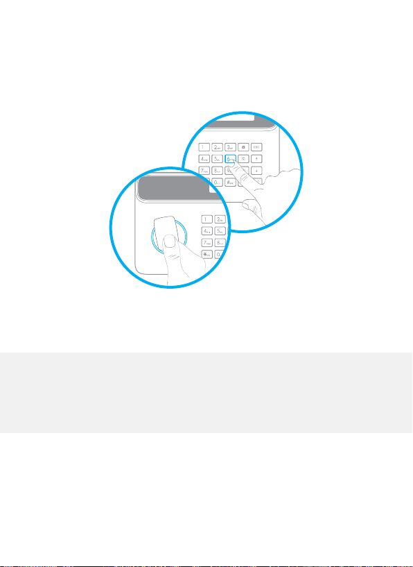
Arbeiten mit dem Bedienfeld
Page 45
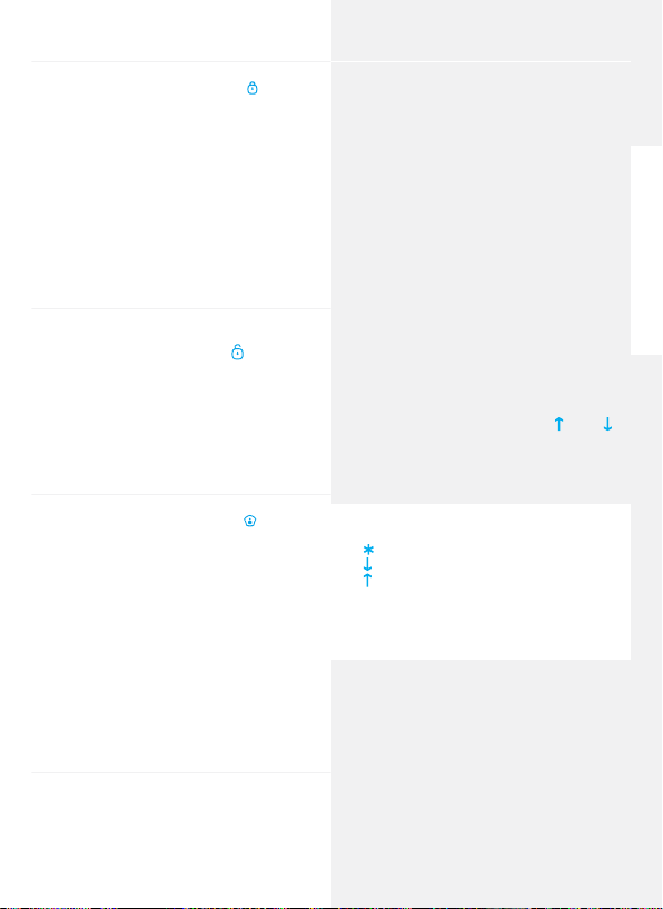
Aktivierung des Systems
Drücken Sie die Aktivierungstaste " " auf dem
Bedienfeld. Das Bedienfeld gibt einen Piepton
aus: das System ist aktiviert.
Hinweis
Bei aktivierter Eingangs-/Ausgangsverzögerung
wird nach der festgelegten Verzögerung
nur die Verzögerungszone aktiviert (siehe
Anweisungen auf Seite 11 dieses Handbuchs
“Eingangs-/Ausgangsverzögerung”).
Deaktivierung des Systems
Geben Sie Ihren Benutzercode ein und drücken
Sie die Deaktivierungstaste "
Bedienfeld. Das Bedienfeld gibt einen Piepton
aus: das System ist deaktiviert.
Standard-Benutzercode: 1234
" auf dem
Home-Modus
Drücken Sie die Aufenthaltstaste " " auf dem
Bedienfeld. Das Bedienfeld gibt einen Piepton
aus: das System ist aktiviert und bendet sich
im Home-Modus.
Alle Sensoren, die der Normalzone zugewiesen
sind, werden aktiviert. Alle Sensoren, die
der Home-Zone zugewiesen sind, werden
deaktiviert.
Weitere Informationen über die Zoneneinrichtung
nden Sie in den Anweisungen auf Seite 14
dieses Handbuchs.
Notfall-Modus
Halten Sie die Taste “#
gedrückt. Der Alarm wird sofort ausgelöst
und die Sirene ertönt. Gleichzeitig wählt das
Bedienfeld die gespeicherten Telefonnummern.
” 3 Sekunden lang
SOS
Einrichtung per Bedienfeld
Das Bedienfeld Ihres Alarmsystems ist mit
einem LCD-Display ausgestattet, mit dem Sie
durch das Menü des Bedienfelds navigieren
und Ihr Alarmsystem einrichten können.
Um das Einrichtungsmenü zu önen, geben Sie
auf dem Bedienfeld [Ihren Admin-Code ein und
drücken Enter].
Standard-Admin-Code: 123456
In der Tabelle auf der nächsten Seite
repräsentiert jede Spalte ein Menü oder ein
Untermenü. Jedes Menü oder Untermenü
wird auf einer der beiden Zeilen des LCDDisplays angezeigt. Im LCD-Display werden das
aktuelle Menü, Untermenü oder Einstellung
in der unteren Zeile angezeigt, während das
vorherige Menü oder Untermenü in der oberen
Zeile angezeigt werden.
Navigieren Sie mithilfe der Tasten “
” zur gewünschten Einstellung und önen Sie
ein Menü oder Untermenü durch Drücken auf
“Enter”.
Verwendung der Tastatur
“ “ = löschen
“
” = vorwärts
“
” = zurück
“Enter” = Auswahl/bestätigen
“Esc” = zurück/Schritt zurück im Menü/
abbrechen
In den Tabellen auf den nächsten Seiten werden
alle Einstellungen zusammengefasst, die über
das Bedienfeld vorgenommen werden können.
” und “
Zubehör Sicherheit und FehlerbehebungSchnellstart Arbeiten mit dem Bedienfeld Arbeiten mit SMS
9
Page 46
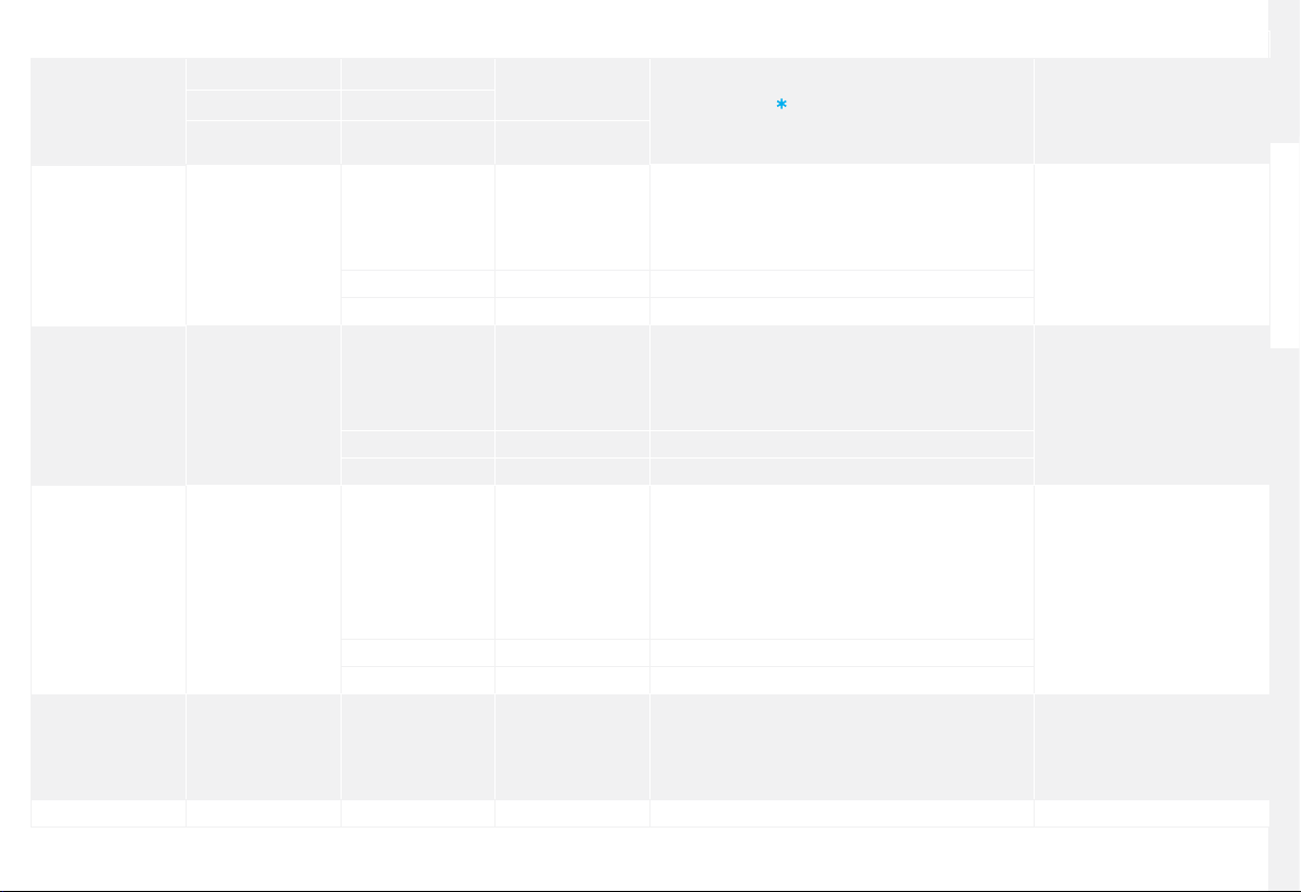
Hauptmenü Untermenü 1 Untermenü 2 Untermenü 3 Kommentare Hinweis
TELEFON 1~5:
TELEFONNRN.
ZUBEHÖR
ZUBEHÖR RFIDTAG
ZUBEHÖR FUNKSENSOR
ZUBEHÖR TESTMODUS
SYSTEMEINSTELL. DATUM UND UHRZ. JJJJMMTT UHRZEIT z. B. 20140620 14.30 UHR
SMSNR. 1~5:
CMSNR. 1~2:
FERNBEDIENUNG
(und Funktastatur)
NEU HINZUFÜGEN
ALLE LÖSCHEN 1=JA 0=NEIN
EINE LÖSCHEN 0130 E INGEB.: Wählen Sie die zu löschende Fernbedienung aus.
NEU HINZUFÜGEN KTO. VERBINDEN
ALLE LÖSCHEN 1=JA 0=NEIN
EINE LÖSCHEN 0150 EINGEBEN: Wählen Sie den zu löschenden RFID-Tag aus.
NEU HINZUFÜGEN
ALLE LÖSCHEN 1=JA 0=NEIN
EINE LÖSCHEN 0150 EINGEBEN:
NORMAL
HOME
VERZÖGERUNG
24 STUNDEN
Wählen Sie die zu bearbeitende SMS-Nummer oder Telefonnummer,
geben Sie die Telefonnummer ein und bestätigen Sie mit der Taste
"Enter". M it der Taste "
5 Telefonnummern, 5 SMS-Nummern und 2 CMS-Nummern können
im Bedienfeld gespeichert werden.
Auf dem LCD-Bildschirm wird “BIT VERBINDEN 30” angezeigt:
drücken Sie jetzt innerhalb von 30 Sekunden eine beliebige Taste
auf der Fernbedienung (der Countdown wird auf dem Bildschirm
nach "BIT VERBINDEN" in Sekunden angezeigt). Es wird ein
Piepton ausgegeben und auf dem LCD-Bildschirm wird “HINZ OK!
FERNBEDIENUNG [01~30]” angezeigt: die Verbindung war erfolgreich.
Auf dem LCD-Bildschirm wird “ BIT VERBINDEN 30” angezeigt: drü-
cken Sie jetzt innerhalb von 30 Sekunden den RFID-Tag über das
RFID-Lesegerät auf dem Bedienfeld (der Countdown wird auf dem
Bildschirm nach "BIT VERBINDEN" in Sekunden angezeigt). Es wird
ein Piepton ausgegeben und auf dem LCD-Bildschirm wird “HINZ
OK! RFID [01~50]” angezeigt, die Verbindung war erfolgreich.
Wählen Sie den Sensortyp aus, dem Ihr Sensor zugewiesen werden
soll (Normalsensor, 24-Stunden-Sensor, Verzögerungssensor oder
Home-Sensor) und drücken Sie zur Bestätigung “Enter”.
Auf dem LCD-Bildschirm wird “ BIT VERBINDEN 30” angezeigt:
lösen Sie jetzt innerhalb von 30 Sekunden den Melder aus (der
Countdown wird auf dem Bildschirm nach "BIT VERBINDEN" in
Sekunden angezeigt). Es wird ein Piepton ausgegeben und auf
dem LCD-Bildschirm wird “HINZ OK! SENSOR 01~50” angezeigt,
die Verbindung war erfolgreich.
Lösen Sie die Sensoren aus, die Sie zuvor mit dem Bedienfeld
verbunden haben. Sie hören 1 Piepton und der LCD-Bildschirm zeigt
die Signale an, die jeweils von den einzelnen ausgelösten Sensoren
gesendet wurden. Stellen Sie sicher, dass alle von Ihnen ausgelösten
Sensoren auf dem LCD-Bildschirm angezeigt werden. Drücken Sie
“Esc”, um den Testmodus zu beenden.
" kann gelöscht werden.
Anweisungen für die Eingabe einer
CMS-Center-Telefonnummer nden Sie
auf der Seite 14 dieses Handbuchs.
Weitere Informationen über die
Zoneneinrichtung nden Sie in den
Anweisungen auf Seite 14.
Mit diesem Modus können die Sensoren
getestet werden, die erfolgreich mit
dem Bedienfeld verbunden wurden.
Zubehör Sicherheit und FehlerbehebungSchnellstart Arbeiten mit dem Bedienfeld Arbeiten mit SMS
10
Page 47
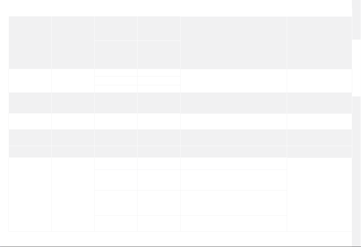
Hauptmenü Untermenü 1 Untermenü 2 Untermenü 3 Kommentare Hinweis
Diese Funktion kann verwendet werden, wenn Sie keine Fernbedie-
EINGANG VERZÖG. 000300
SYSTEMEINSTELL. EING./AUSG. VRZ.
AUSGANG VERZÖGE
RUNG
AUTO AKT.ZEIT <00:00>
SYSTEMEINSTELL. AUTO AKT./DEAKT.
SYSTEMEINSTELL. STEUER. PER TEL. EIN/AUS
SYSTEMEINSTELL. LTGUNTERB. ALARM EIN/AUS
SYSTEMEINSTELL. GSM FEHL TIP EIN/AUS Benachrichtigung bei SIM-/GSM-Signalproblem.
SYSTEMEINSTELL. TASTATURKLICK EIN/AUS
SYSTEMEINSTELL. ZUGANGSCODE
ZEIT AUT. DEAK T. <00:00>
EIN ODER AUS?
ADMINCODE 123456
BENUTZERCODE 1234
NOTRUFCODE 0000
CODE F. OFF. TÜR 8888
000300
nung oder RFID-Tags mit sich führen möchten. Bei der Aktivierung
des Systems wird jede Sekunde ein Piepton ausgegeben, der Sie
daran erinnert, die Wohnung zu verlassen. Der Pieptonrhythmus
beschleunigt sich während der letzten 10 Sekunden. Bei Erkennung eines Eindringlings wird der Alarm entsprechend verzögert.
Die Zeit wird in Sekunden berechnet. Die Eingangs- und Ausgangsverzögerung kann zwischen 0 und 300 Sekunden eingestellt
werden.
Das System kann so eingerichtet werden, dass eine Aktivierung
oder Deaktivierung automatisch zu einer festgelegten Tageszeit
erfolgt.
Die Steuerung Ihres Systems kann per Telefonanruf aktivier t oder
deaktiviert werden. Durch die Aktivierung der Steuerung per Tele fon können das System aktiviert und deaktiviert und Ihr Eigenheim
per Telefonanruf überwacht werden.
Bei aktiviertem Alarm bei Leitungsunterbrechung wird der Alarm bei ausgefallener Telefonleitung ausgelöst. Die erste gespeicherte SMS-Nummer
erhält dann eine Benachrichtigung per SMS (nur im GSM-Modus).
Aktivierung oder Deaktivierung des Tons bei Eingabe mit der
Tastatur des Bedienfelds.
Mit dem Admin-Code gelangen Sie in das Einrichtungsmenü.
Standard-Admin-Code: 123456
Mit Ihrem Benutzercode können Sie das System am Bedienfeld aktivieren oder deaktivieren. Der Benutzercode ist der Zugangscode,
der bei Anruf des Bedienfelds angefordert wird.
Standard-Benutzercode: 1234
Muss bei einem Notfall die Deaktivierung des Systems erzwungen
werden, wird empfohlen, das System anhand des Notrufcodes
zu deaktivieren. Das Bedienfeld wählt lautlos die gespeicherten
Telefonnummern.
Standard-Notrufcode: 0000
Mit diesem Code können elektronische Türen geönet werden.
Die Tür muss mit der [SCHLOSS]-S chnittstelle auf der Rückseite des
Bedienfelds verkabelt sein.
Die Eingangs- und Ausgangsverzögerung
gilt nur für Sensoren, die mit dem Zubehör
der Verzögerungszone verbunden sind
(siehe "Funksensor" auf Seite 10).
Mit der Eingangsverzögerung erhalten
Sie die Zeit für die Deaktivierung des
Systems am Bedienfeld, ohne einen Alarm
auszulösen.
Mit der Ausgangsverzögerung erhalten Sie
die Zeit für die Aktivierung des Systems am
Bedienfeld, ohne einen Alarm auszulösen.
Die Einstellung von Auto Akt. und
Auto Deakt. auf die exakt gleiche Zeit
deaktiviert die Funktion.
Anweisungen und Informationen über
die Steuerung des Systems per Telefonanruf nden Sie auf Seite 13.
Deaktivieren Sie diese Funktion, wenn
Sie das Alarmsystem nur im GSM-Modus verwenden möchten.
Deaktivieren Sie diese Funktion, wenn
Sie das Alarmsystem nur im PSTN-Modus verwenden möchten.
Vor der ersten Verwendung des
Systems wird empfohlen, alle Codes
zu ändern und die Codes geheim zu
halten.
Zubehör Sicherheit und FehlerbehebungSchnellstart Arbeiten mit dem Bedienfeld Arbeiten mit SMS
11
Page 48
Hauptmenü Untermenü 1 Untermenü 2 Untermenü 3 Kommentare Hinweis
SYSTEMEINSTELL. ERTÖNUNGSZEIT <09>
SIRENENUMSCHALT.
VERK. SIRENE
SIRENENLAUTSTÄRKE 01 0=STUMM
SIRENE TONDAUER 3 MIN
SYSTEMEINSTELL. SIRENENEINRICHT.
INTEGR. SIRENE
FUNKSIRENE
SYSTEMEINSTELL. BENUTZERID 4 ZIFFERN:0000
SYSTEMEINSTELL.
SYSTEMEINSTELL. ANRUFWIEDERH. <09>
SYSTEMEINSTELL. HTGR.LICHT ZEIT <000300> 030 S
SYSTEMEINSTELL. SPRACHE Änderung der Systemsprache.
SYSTEMEINSTELL. RESET
SYSTEMEINSTELL. ÜBER ÜBER 4. JU N 2014
VERLAUF - - -
UPLOAD AKT. EIN/AUS Aktivierung Benachrichtigung per SMS (Nur GSM-Modus)
UPLOAD DEAKT. EIN/AUS Deaktivierung Benachrichtigung per SMS (Nur GSM-Modus)
<EIN ODER AUS?>
TON AKT./DEAKT. <EIN
ODER AUS?>
SIRENENUMSCHALT.
<EIN ODER AUS?>
TON AKT./DEAKT. <EIN
ODER AUS?>
SIRENENUMSCHALT.
<EIN ODER AUS?>
TON AKT./DEAKT. <EIN
ODER AUS?>
Mit dieser Funktion kann festgelegt werden, wie oft das Bedienfeld klingelt,
bevor der Anruf angenommen wird (für die Steuerung per Telefonanruf ).
Kabelsirene bezieht sich auf eine Sirene,
die per Kabel mit dem Bedienfeld
verbunden ist.
Die Sirenentondauer wird in Minuten berechnet, die
Standardeinstellung lautet 3 Minuten. Wird die Tondauer auf 0
festgelegt, ertönt die Sirene nicht.
Die integrierte Sirene bezieht sich auf
die in das Bedienfeld integrierte Sirene.
Funksirene bezieht sich auf eine Sirene,
die per Funk mit dem Bedienfeld
verbunden ist.
Weitere Informationen nden Sie auf der Seite 14 dieses Handbuchs. Diese Information erhalten Sie von Ihrem CMS-Center. Nach der Speicherung der Benutzer-ID kann das CMS-Center entsprechend Ihrer ID-Nummer
Ihren exakten Standort bestimmen.
Bei ausgelöstem Alarm wählt das Bedienfeld die von Ihnen gespeicherten Nummern. Wird das System nicht deaktiviert, werden
Sie erneut vom Bedienfeld angerufen (bis zu neunmal). Mit der
Funktion "Anrufrückf." kann die Anzahl festgelegt werden, wie oft
das Bedienfeld versucht, Sie anzurufen.
Die verfügbaren Sprachen sind abhängig von der Produktversion.
Alle Systemeinstellungen werden auf die Standardwerte zurückgesetzt.
Gespeicherte Telefonnummern und verbundenes Zubehör werden
gelöscht.
Wählen Sie das gewünschte Ereignisprotokoll und drücken Sie
“Enter”.
Die letzten 150 Ereignisprotokolle werden vom Bedienfeld gespeichert.
Zubehör Sicherheit und FehlerbehebungSchnellstart Arbeiten mit dem Bedienfeld Arbeiten mit SMS
12
Page 49
Steuerung per Telefonanruf
Diese Funktion ist nur dann verfügbar, wenn sie im Bedienfeld aktiviert wurde, wie auf Seite 11 dieses
Handbuchs erläutert.
Methode 1
Wird ein Alarm ausgelöst, werden vom Bedienfeld die gespeicherten Telefonnummern gewählt. Bei
Annahme des Anrufs kann das Bedienfeld unter Beachtung der Sprachanweisungen von der Distanz
aus gesteuert werden.
Methode 2
1. Wählen Sie die Telefonnummer Ihres Bedienfelds (entweder die Nummer der SIM-Karte in
Ihrem Bedienfeld oder die Nummer des Festnetzes, mit dem Ihr Bedienfeld verbunden ist). Nach
Verbindungsherstellung wird anhand der Sprachanweisungen der Zugangscode eingegeben.
2. Geben Sie Ihren Zugangscode (Benutzercode) ein, gefolgt von einem ”#”.
3. Sie erhalten per Sprache verschiedene Auswahlmöglichkeiten.
4. Wählen Sie aus den Tätigkeiten zur Steuerung des Bedienfelds (siehe Anweisungen in der folgenden
Tabelle).
Hinweis
Wird innerhalb von 30 Sekunden kein Befehl gesendet, wird der Anruf automatisch beendet.
Befehlstabelle für die Steuerung per Telefonanruf
Befehl Funktion Kommentar
Drücken
Sie “1“
Drücken
Sie “0“
Drücken
Sie “
Drücken
Sie “3“
Drücken
Sie “6“
Drücken
Sie “9“
Drücken
Sie “#“
Aktiviert das System Sprachansage “System aktiviert”
- Deaktiviert das System und die Sirene wird
ausgeschaltet
- Beendet die Überwachung, ohne aufzulegen
- Beendet den Telefonanruf, ohne aufzulegen
Audioüberwachung
“
Telefonanruf mit Bedienfeld -
Schaltet die Sirene aus -
Schaltet die Sirene ein -
- Deaktiviert das System und die Sirene wird
ausgeschaltet
- Beendet die Steuerung per Telefonanruf
Sprachansage “System deaktiviert”
Drücken Sie “
chungszeit zu verlängern
Durch das Auegen wird auch
die Steuerung per Telefonanruf
beendet.
”, um die Überwa-
Zubehör Sicherheit und FehlerbehebungSchnellstart Arbeiten mit dem Bedienfeld Arbeiten mit SMS
13
Page 50

Hinweis
Im GSM-Modus gibt es keine zeitliche Einschränkung für die Audioüberwachung.
Im PSTN-Modus (verbunden mit Ihrem Festnetz), ist die Audioüberwachung auf 80 Sekunden
begrenzt. Soll die Zeit für die Audioüberwachung verlängert werden, drücken Sie “ ” auf Ihrem
Telefon, bevor die 80 Sekunden abgelaufen sind.
Zoneneinrichtung von Zubehör
Jeder Melder kann 4 verschiedenen Zonenkategorien zugewiesen werden: Home-Zone,
Verzögerungszone, Normalzone und 24-H-Zone. Anweisungen für die Zuweisung eines Melders zu
einer Zone nden Sie auf Seite 10 dieses Handbuchs (die Zone wird zum Zeitpunkt der Verbindung
des Zubehörs zugewiesen).
Normalzone
Wird bei aktiviertem System ein Sensor ausgelöst, ertönt die Sirene. Ist das System deaktiviert, lösen
die Sensoren keinen Alarm aus.
24 h-Zone
Die der 24 h-Zone zugewiesenen Sensoren können sowohl bei aktiviertem als auch bei deaktiviertem
System einen Alarm auslösen. Es wird empfohlen, Rauchmelder, Gasmelder und Außenlichtsensoren der
24 h-Zone zuzuweisen.
Verzögerungszone
Für die Einrichtung der Funktionen der Eingangs- und Ausgangsverzögerung müssen die
entsprechenden Sensoren der Verzögerungszone zugewiesen werden. Nachdem die Verzögerungszeit
eingerichtet wurde, wird während der festgelegten Verzögerung kein Alarm ausgelöst. Folgen Sie
dafür den Anweisungen "Eingangs- und Ausgangsverzögern" auf der Seite 10 dieses Handbuchs. Es
wird empfohlen, den Tür-/Fenster-Kontakt der Verzögerungszone zuzuweisen.
Home-Zone
Wird das System im Home-Modus aktiviert, lösen die der Home-Zone zugewiesenen Sensoren keinen
Alarm aus. Es wird empfohlen, der Home-Zone Bewegungsmelder zuzuweisen, damit das System im Home-
Modus aktiviert werden kann, wenn Sie Zuhause sind und sich darin bewegen können, ohne den Alarm
auszulösen.
Verbindung zum CMS-Center
Ignorieren Sie diesen Schritt, wenn Sie nicht mit einem CMS-Center verbunden sind. Besteht eine
Verbindung zu einem CMS-Center, wird das Bedienfeld bei Erkennung eines Eindringens automatisch
Ihre Kontakt-ID zum CMS-Center hochladen.
Zubehör Sicherheit und FehlerbehebungSchnellstart Arbeiten mit dem Bedienfeld Arbeiten mit SMS
14
Page 51
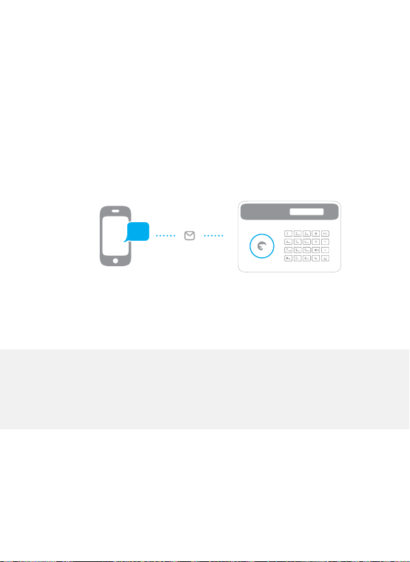
...
Arbeiten mit SMS
Page 52
Arbeiten mit SMS
Deaktivierung des Systems
WICHTIG: VOR DER ERSTEN
VERWENDUNG
STECKEN SIE VOR DER ARBEIT MIT SMS
EINE SIMKARTE IN DAS BEDIENFELD EIN.
STELLEN SIE SICHER, DASS DIE SIM
KARTE NICHT DURCH EINEN PINCODE
GESCHÜTZT IST.
SPEICHERN SIE EINE SMSNUMMER
IM BEDIENFELD AB MITHILFE DES
BEDIENFELDS.
Nur über gespeicherte Nummern kann das
System gesteuert und konguriert werden.
Siehe Anweisungen auf Seite 10)
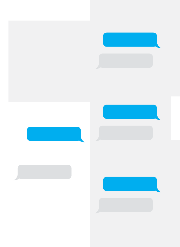
Jeder, in diesem Benutzerhandbuch denierte
SMS-Vorgang, wird wie folgt dargestellt:
Sie senden:
SMS-Befehl
Die erste blaue Sprechblase steht für den
vom Benutzer gesendeten SMS-Befehl.
Das Bedienfeld antwortet:
Antwort des Bedienfelds
Die erste graue Sprechblase steht für die vom
Bedienfeld gesendete Antwort.
Bei den danach folgenden Sprechblasen handelt
es sich um den Dialog zwischen Anwender und
Bedienfeld (vom Anwender gesendete SMS sind
blau, vom Bedienfeld gesendete SMS sind grau).
Das System ist standardmäßig auf Englisch
eingestellt. Anweisungen für die Änderung der
Systemsprache nden Sie auf der Seite 21
dieses Handbuchs.
Senden:
0
System deaktiviert
Aktivierung des Systems
Senden:
1
System aktiviert
Home-Modus
Senden:
2
System in Home-Modus
Zubehör Sicherheit und FehlerbehebungSchnellstart Arbeiten mit dem Bedienfeld Arbeiten mit SMS
16
Page 53

Einstellungsabfrage
Senden:
00
Speicherung von
Telefonnummern
Senden:
5
System: Deaktiviert
Strom: eingeschaltet
Hinweis
Die oben angegebenen Werte ändern sich nach
der Einrichtung des Systems.
TEL:
1.
2.
3.
4.
5.
Kopieren, einfügen dann bearbeiten
(Groß-/Kleinschreibung beachten):
TEL:
1. 067890033
2. 067890022
3. 067890011
4. 067890000
5.
OK
Zubehör Sicherheit und FehlerbehebungSchnellstart Arbeiten mit dem Bedienfeld Arbeiten mit SMS
17
Page 54

Speicherung von
Telefonnummern für SMSBenachrichtigungen
Senden:
6
SMS:
1.
2.
3.
4.
5.
Kopieren, einfügen dann bearbeiten
(Groß-/Kleinschreibung beachten):
Zonen umbenennen
Senden Sie "91~99". Für Zone 1 senden Sie
beispielsweise:
91
Zonenname:
1.
Kopieren, einfügen dann bearbeiten
(Groß-/Kleinschreibung beachten):
Zonenname:
1. Eingangstür-Sensor
SMS:
1. 067890033
2. 067890022
3. 067890011
4. 067890000
5.
OK
Hinweis
Wird das System per RFID-Tag deaktiviert,
werden SMS-Benachrichtigungen an die
erste SMS-Nummer gesendet. Um diese
Benachrichtigungen zu erhalten, müssen die
RFID-Tags umbenannt werden. Es können
bis zu 4 RFID-Tags umbenannt werden.
Den anderen Tags wird auf der Basis der
Registrierungsreihenfolge im Bedienfeld eine
Nummer zugewiesen. Weitere Anweisungen
für die Registrierung eines RFID-Tags im
Bedienfeld erhalten Sie auf Seite 10.
OK
Hinweis
Die Zonen 1 bis 9 können umbenannt werden.
Der Name der Zone darf aus höchstens 30
lateinischen Zeichen bestehen. Die Zonen 10
bis 50 können umbenannt werden.
Zubehör Sicherheit und FehlerbehebungSchnellstart Arbeiten mit dem Bedienfeld Arbeiten mit SMS
18
Page 55
SMS-Benachrichtigung bei
schwacher Batterie des Zubehörs
(verfügbar für 2-Wege-Zubehör, wie z. B.
Bewegungsmelder)
RFID-Tag umbenennen
Senden:
Für Zubehör, das umbenannten Zonen
zugewiesen wurde, wird eine SMS des Formats
“Zonenname + BAT nie.” gesendet.
Schlafzimmer BAT nie.
Für Zubehör, das nicht umbenannten Zonen
zugewiesen wurde, wird eine SMS des Formats
“Zonennummer + BAT nie.” gesendet.
Zone 10 BAT nie.
SMS-Benachrichtigung bei
Sabotagealarm des Zubehörs
(verfügbar für 2-Wege-Zubehör, wie z. B.
Bewegungsmelder)
Für Zubehör, das umbenannten Zonen
zugewiesen wurde, wird eine SMS des Formats
“Zonenname + Sabot.” gesendet.
Schlafzimmer Sabot.
Für Zubehör, das nicht umbenannten Zonen
zugewiesen wurde, wird eine SMS des Formats
“Zonennummer + Sabot.” gesendet.
Zone 10 Sabot.
10
RFID-Tags umbenennen:
1.
2.
3.
4.
Kopieren, einfügen dann bearbeiten
(Groß-/Kleinschreibung beachten):
RFID-Tags umbenennen:
1. Tom
2. Peger
3. Nancy
4. David
OK
Hinweis
Wird das System per RFID-Tag deaktiviert,
werden SMS-Benachrichtigungen an die
erste SMS-Nummer gesendet. Um diese
Benachrichtigungen zu erhalten, müssen die
RFID-Tags umbenannt werden. Es können
bis zu 4 RFID-Tags umbenannt werden.
Den anderen Tags wird auf der Basis der
Registrierungsreihenfolge im Bedienfeld eine
Nummer zugewiesen. Weitere Anweisungen
für die Registrierung eines RFID-Tags im
Bedienfeld erhalten Sie auf Seite 10.
Zubehör Sicherheit und FehlerbehebungSchnellstart Arbeiten mit dem Bedienfeld Arbeiten mit SMS
19
Page 56
Verzögerungszeit für Ein- und
Ausgang
Senden:
11
Eingang Verzögerungszeit (0-300 s): 0
Ausgang Verzögerungszeit (0-300 s): 0
Sirenenlautstärke und Tondauer
Senden:
12
Sirenenlautstärke (0=stumm,1=hoch):
1
Sirene Tondauer (1-9 min):
5
Kopieren, einfügen dann bearbeiten
(Groß-/Kleinschreibung beachten):
Eingang Verzögerungszeit (0-300 s):10
Ausgang Verzögerungszeit (0-300 s):20
OK
Hinweis
Diese Funktion wirkt sich nur auf Melder aus, die
der Verzögerungszone zugewiesen sind. Weitere
Informationen über die Einrichtung Ihres Sensors
für die Verzögerungszone nden Sie auf Seite
10.
Diese Funktion kann verwendet werden, wenn
Sie keine Fernbedienung oder RFID-Tag mit sich
führen möchten.
Wenn Sie das System aktivieren, wird das System
nach der festgelegten Verzögerung aktiviert.
Wenn Sie das System deaktivieren, wird das
System nach der festgelegten Verzögerung
deaktiviert.
Bei der Aktivierung des Systems wird jede
Sekunde ein Piepton ausgegeben, der Sie
daran erinnert, die Wohnung zu verlassen. Der
Pieptonrhythmus beschleunigt sich während
der letzten 10 Sekunden. Wird ein Eindringling
erkannt, wird der Alarm entsprechend verzögert.
Kopieren, einfügen dann bearbeiten
(Groß-/Kleinschreibung beachten):
Sirenenlautstärke (0=stumm,1=hoch):
0
Sirene Tondauer (1-9 min):
3
OK
Zubehör Sicherheit und FehlerbehebungSchnellstart Arbeiten mit dem Bedienfeld Arbeiten mit SMS
20
Page 57
Deaktivierungspasswort
Systemsprache ändern
Senden:
13
Deaktivierungspasswort (4 Ziern):
1234
Kopieren, einfügen dann bearbeiten
(Groß-/Kleinschreibung beachten):
Deaktivierungspasswort (4 Ziern):
8888
OK
Senden Sie den Code entsprechend der Sprache, die Sie festlegen möchten. Für Englisch
beispielsweise senden Sie “0001”.
0001
OK
Die folgende Tabelle enthält eine vollständige
Liste der Sprachen:
0001 Englisch
0002 Französisch
0003 Russisch
0004 Dänisch
0005 Niederländisch
0006 Italienisch
0007 Schwedisch
Die verfügbaren Sprachen sind abhängig von
der Produktversion.
0008 Deutsch
0009 Spanisch
0010 Finnisch
0011 Norwegisch
0012 Arabisch
0013 Farsi
Zubehör Sicherheit und FehlerbehebungSchnellstart Arbeiten mit dem Bedienfeld Arbeiten mit SMS
21
Page 58
Zurücksetzen des Systems auf
Werkseinstellungen
Senden:
0000
OK
Die Einstellungen werden jetzt auf die
Standardwerte zurückgesetzt. Gespeicherte
Telefonnummern und verbundenes Zubehör
werden nicht gelöscht.
Hinweis
Nur gespeicherte Nummern können die SMS
für das Zurücksetzen der Werkseinstellungen
senden.
Zubehör Sicherheit und FehlerbehebungSchnellstart Arbeiten mit dem Bedienfeld Arbeiten mit SMS
22
Page 59
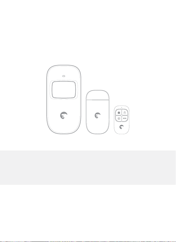
Zubehör
Page 60
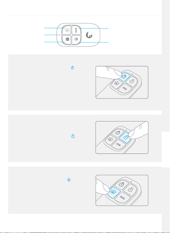
Funkfernbedienung
Deaktivieren
LED-Anzeige
Aktivieren
Aktivierung des Systems
Drücken Sie die Aktivierungstaste " " zur
Aktivierung des Alarmsystems. Die LED-Anzeige
leuchtet auf (das Bedienfeld gibt einen Piepton
aus). Das System ist aktiviert.
Wird ein Eindringling erkannt, ertönt die
Sirene. (Mit den Standardeinstellungen schaltet
sich die Sirene nach 5 Minuten aus). In der
Zwischenzeit werden vom System automatisch
die gespeicherten Nummern gewählt.
Deaktivierung des Systems
Drücken Sie die Deaktivierungstaste "
Deaktivierung des Alarmsystems. Die LEDAnzeige leuchtet auf (das Bedienfeld gibt zwei
Pieptöne aus). Das System ist deaktiviert.
Home-Modus
Drücken Sie die Home-Modus-Taste " " auf
der Fernbedienung. Die Systemstatus-LED
leuchtet auf. Alle Sensoren in den regulären
Zonen sind aktiviert, mit Ausnahme der
Sensoren in der Home-Modus-Zone. Die
Sensoren in der Home-Modus-Zone sind
deaktiviert, sodass der Anwender in das Haus
gehen kann.
" zur
SOS
Home-Modus
Zubehör Sicherheit und FehlerbehebungSchnellstart Arbeiten mit dem Bedienfeld Arbeiten mit SMS
24
Page 61
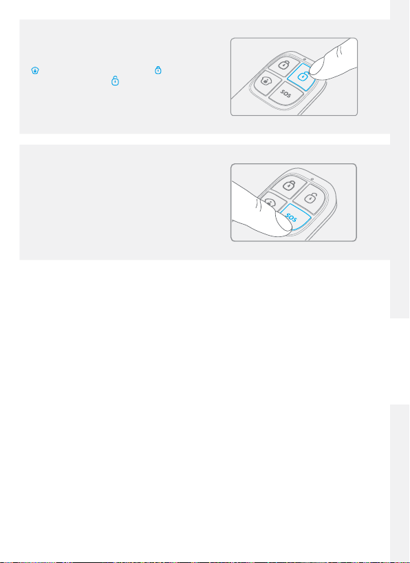
Stumm-Modus
Drücken Sie die Home-Modus-Taste "
" und die Aktivierungstaste " " oder
Deaktivierungstaste "
Auf diese Weise wird das Bedienfeld bei
Aktivierung oder Deaktivierung des Systems
keinen Piepton ausgeben.
Notfall-Modus
Unabhängig vom Systemstatus, wird der
Alarm ausgelöst, sobald die Taste "SOS" auf der
Fernbedienung gedrückt wird.
Gleichzeitig sendet das Bedienfeld eine
Benachrichtigung per SMS ("RC-01 SOS", wobei
01 die Nummer der Fernbedienung ist) und
wählt die vorgespeicherten Telefonnummern.
Registrierung im Bedienfeld
Folgen Sie den Anweisungen in der Tabelle auf Seite 10 dieses Handbuchs "FERNBEDIENUNG".
Anweisungen für die Durchführung der Überprüfung einer korrekten Registrierung nden Sie in der
Tabelle auf Seite 10 (“Testmodus”).
Technische Daten
Stromversorgung
DC 3 V (CR2025 Knopfbatterie x1)
Ruhestrom
≤10 uA
Betriebsstrom
≤7 mA
Übertragungsbereich:
≤ 80 m (in oenen Bereichen)
Radiofrequenz:
433 MHz (±75 KHz)
" direkt danach.
Gehäusematerial
ABS-Kunststo
Betriebsbedingungen
Umgebungstemperatur: -10 °C ~ +55 °C
Relative Luftfeuchtigkeit ≤80 %
(nicht kondensierend)
Maße
57 x 31 x 11 mm
Zubehör Sicherheit und FehlerbehebungSchnellstart Arbeiten mit dem Bedienfeld Arbeiten mit SMS
25
Page 62
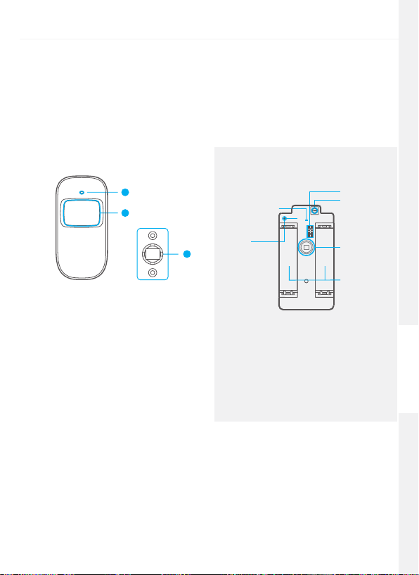
Funkbewegungsmelder
Merkmale
Das ES-D1A ist ein hochleistungsfähiger Funk-Bewegungsmelder mit digitalem Dual-Core FuzzyLogic Infrarot-Kontroll-Chip mit Intelligenzanalyse. Diese Technologie erkennt Störungen, die
durch Körperbewegungen erzeugt werden und reduziert die Anzahl von Fehlalarmen.
Mit automatischem Temperaturausgleich und Anti-Luftwirbel-Technologie ausgestattet, passt sich
dieser den Veränderungen der Umwelt an.
3
PCB-Layout
LED-Funktions-
anzeige
Antenne
Alarmzoneneinrichtung
Sabotagekontakt*
Infrarotsen-
sor**
Design
1
2
AA 1,5 V LR6
1. LED-Anzeige
2. Erkennungsfenster.
3. Halterung
* Sabotagekontakt
Bei aktiviertem Sabotagekontakt wird der
Sabotagekontakt bei Önen des Gehäuses
automatisch den Alarm auslösen.
**Infrarotsensor
Erkennt die durch die Bewegung des
menschlichen Körpers freigegebene
Infrarotstrahlung. Die Oberäche nicht
berühren. Die Oberäche sauber halten.
LED-Anzeigen
Dauerblinken: Selbsttest
Einmal blinken: Ein Eindringling wurde erkannt
Zweimal blinken: Selbsttest ist abgeschlossen; Wechsel in den Arbeitsmodus.
Blinken im 3-Sekunden-Abstand: Unterspannungshinweis: Die Batterien müssen ersetzt werden.
(Der Anwender wird bei leeren Batterien per SMS informiert, sofern der Melder im Bedienfeld
registriert wurde).
Zubehör Sicherheit und FehlerbehebungSchnellstart Arbeiten mit dem Bedienfeld Arbeiten mit SMS
26
Page 63
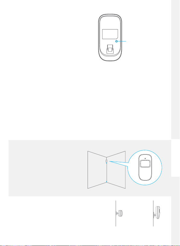
Verwendung
Önen Sie das Gehäuse und entfernen Sie
den Streifen für die Batterieaktivierung.
Der 30 Sekunden dauernde Selbsttest wird
durchgeführt.
Wird der Sensor bei Betrieb innerhalb von 3
Minuten mehr als zweimal ausgelöst, wechselt
dieser zur Stromeinsparung in den StandbyModus. Wird innerhalb der nächsten 3 Minuten
keine Bewegung erkannt, wechselt der Sensor
zurück in den Arbeitsmodus.
Registrierung im Bedienfeld
Navigieren Sie durch das Menü des Bedienfelds zu "NEU" (Funksensor). Drücken Sie die
Verbindungstaste auf der Rückseite des Bewegungssensors oder lösen Sie den Sensor aus (indem Sie
sich davor bewegen), um den Melder im Bedienfeld zu registrieren.
Anweisungen für die Durchführung der Überprüfung einer korrekten Registrierung nden Sie in der
Tabelle auf Seite 10 "TESTMODUS".
Installation
Vermeiden Sie eine Montage des Melders in der Nähe von Fenstern, Klimaanlagen, Heizungen,
Kühlschränken, Öfen, Sonneneinstrahlung und an Orten mit rapiden Temperaturgegensätzen oder
mit stetigem Luftstrom.
Werden zwei Melder im selben Erkennungsbereich montiert, die Position verändern, um Störungen
und Fehlalarme zu vermeiden.
Verbindungstaste
Montieren Sie die Halterung mit Schrauben
an der Wand und befestigen Sie den Melder
an der Halterung. Die Halterung kann für
die Änderung von Erkennungsbereich und
-winkel justiert werden. Es wird empfohlen,
den Melder 2,2 Meter über dem Boden zu
montieren.
Der Melder reagiert auf
Kreuzbewegungen mehr, als auf
Vertikalbewegungen.
2,2 m
Boden
Ansicht von oben
Oben
Unten
Seitenansicht
Zubehör Sicherheit und FehlerbehebungSchnellstart Arbeiten mit dem Bedienfeld Arbeiten mit SMS
27
Page 64
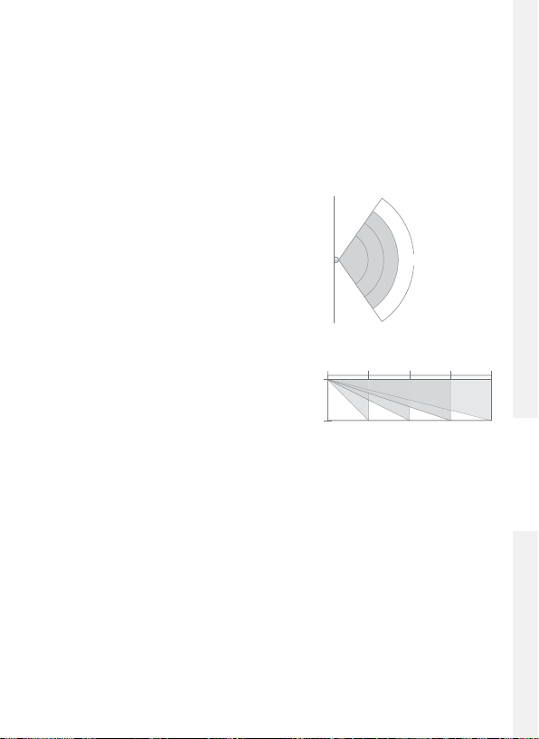
Test
A. Den Melder nach der Installation einschalten. Nach dem einminütigen Selbsttest drücken Sie die
Test-Taste, laufen in den Erkennungsbereich und beobachten die LED-Anzeige, um so die korrekte
Funktion des Melders zu prüfen.
B. Die LED-Anzeige blinkt einmal bei Erkennung von Körperbewegung.
C. Passen Sie den Erkennungswinkel an, um so die beste Erkennungsleistung zu erreichen.
Technische Daten
Stromversorgung
DC 3 V (AA 1,5 V LR6-Batterien x 2)
Ruhestrom
≤ 30uA
Alarmstrom
≤ 15 mA
Erkennungsbereich
8 m / 110 °
Übertragungsbereich:
≤ 80m (in oenen Bereichen)
Radiofrequenz
433 MHz (±75 KHz)
Gehäusematerial
ABS-Kunststo
Betriebsbedingungen
Temperatur: -10 °C~55 °C
Relative Luftfeuchtigkeit: ≤80 % (nicht
kondensierend)
Melderabmessungen (L x B x H)
107 x 53 x 32 mm
Melderabmessungen (L x B x H)
52 x 30 x 26,5 mm
Erkennungsbereich
110°
Ansicht von oben
0m 2m 4m 6m 8m
2m
0m
Seitenansicht
Zubehör Sicherheit und FehlerbehebungSchnellstart Arbeiten mit dem Bedienfeld Arbeiten mit SMS
28
Page 65
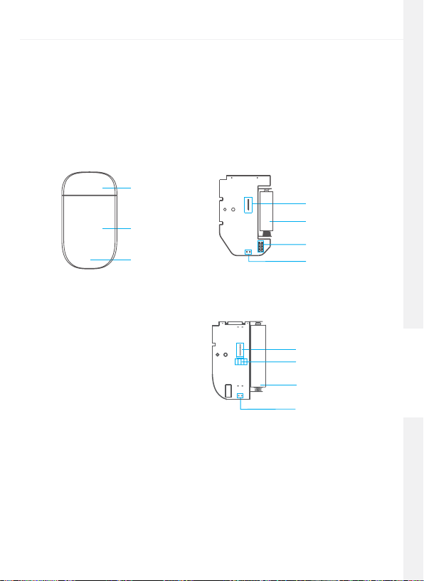
Tür-/Fenster-Funkkontakt
Merkmale
Der ES-D3A/B/C ist ein Tür-/Fensterkontakt, der an Türen, Fenstern und anderen, sich önenden und
schließenden Objekten, angebracht werden kann. Der Sensor sendet ein Signal an das Bedienfeld,
sobald der Magnet vom Sender getrennt wird.
Dank des Sabotagekontakts wird jeder Versuch, die Abdeckung des Tür-/Fensterkontakt zu entfernen,
den Alarm auslösen.
Design
Magnet
Sender
LED-Anzeige
PCB-Layout (ES-D3A/ES-D3B)
Sabotagekontakt
A23 12 V-Batterie
Zoneneinstellung
LED-Funktionsanzeige
LED-Anzeigen
Einmal blinken: Tür oder Fenster ist geönet
und der Sender sendet ein Signal an das
Bedienfeld.
Schnelles Blinken: Niedrigstromhinweis: die
Batterien müssen ersetzt werden.
Registrierung im Bedienfeld
Navigieren Sie durch das Menü des Bedienfelds zu "NEU" (Funksensor). Trennen Sie dann den Magnet
vom Sender, um den Melder im Bedienfeld zu registrieren.
Um eine durchgeführte Registrierung zu überprüfen, das System aktivieren und den Magneten vom
Sender wieder trennen, indem Tür oder Fenster geönet wird, worauf er installiert ist. Ertönt die Sirene,
war die Registrierung erfolgreich. Oder beachten Sie die Anweisungen in der Tabelle auf Seite 10
"TESTMODUS".
PCB-Layout (ES-D3C)
Sabotagekontakt
Jumper für
Zoneneinrichtung
AAA 1.5 V-Batterie
LED-Funktionsanzeige
Zubehör Sicherheit und FehlerbehebungSchnellstart Arbeiten mit dem Bedienfeld Arbeiten mit SMS
29
Page 66
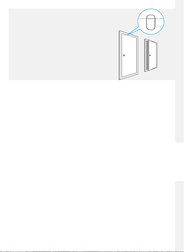
Installation
- Önen Sie das Gehäuse und entfernen Sie den Streifen für die
Batterieaktivierung.
- Befestigen Sie den Sensor an der Tür und den Magneten am
Türrahmen.
- Der Magnet muss unbedingt über dem Sender platziert
werden.
- Montieren Sie den Magnet max. 1 cm vom Sender entfernt
und sichern Sie Sender und Magnet mit doppelseitigem
Klebeband oder Schrauben.
- Vermeiden Sie die Montage des Sensors in Bereichen mit
einer großen Menge von Metall oder Stromleitungen, wie z.
B. in Heizräumen oder Hauswirtschaftsraum.
Technische Daten (ES-D3A/ES-D3B)
Stromversorgung
DC 12 V (A23 12 V-Batterie x 1)
Ruhestrom
≤ 30 uA
Alarmstrom
≤ 15 mA
Übertragungsbereich
≤ 80 m (in oenen Bereichen)
Radiofrequenz
433 MHz (±75 KHz)
Gehäusematerial
ABS-Kunststo
Betriebsbedingungen
Temperatur: -10 °C~55 °C
Relative Luftfeuchtigkeit: ≤80 % (nicht
kondensierend)
Senderabmessungen (LxBxH)
60 x 45 x 18 mm
Magnetabmessungen (LxBxH)
45 x 19 x 17,5 mm
Technische Daten (ES-D3C)
Stromversorgung
AAA 1.5 V Batterie x1
Ruhestrom
≤ 30 uA
Alarmstrom
≤ 15 mA
Übertragungsbereich
≤ 80 m (in oenen Bereichen)
Radiofrequenz
433 MHz (±75 KHz)
Gehäusematerial
ABS-Kunststo
Betriebsbedingungen
Temperatur: -10 °C~55 °C
Relative Luftfeuchtigkeit: ≤80 % (nicht
kondensierend)
Senderabmessungen (LxBxH)
60 x 45 x 18 mm
Magnetabmessungen (LxBxH)
45 x 19 x 17,5 mm
Zubehör Sicherheit und FehlerbehebungSchnellstart Arbeiten mit dem Bedienfeld Arbeiten mit SMS
30
Page 67

RFID-Tag
Merkmale
Mit dem RFID-Tag können Ihr System aktiviert oder deaktiviert oder elektronische Türschlösser
entsperrt werden.
Registrierung im Bedienfeld
Folgen Sie den Anweisungen in der Tabelle auf Seite 10 dieses Handbuchs "RFIDTAG".
Technische Daten
Maße
45 x 30 x 7 mm
Registrierung einer zusätzlichen eTiger-Sirene
Das Bedienfeld des S4 verfügt über eine integrierte 100 dB-Sirene.
Ihre eTiger-Sicherheitssysteme unterstützen das Hinzufügen weiterer Innen- und/oder Außensirenen
und ermöglichen so die Erweiterung Ihres Systems nach Ihren Bedürfnissen.
Anweisungen für die Registrierung einer zusätzlichen eTiger-Sirene nden Sie im der im Lieferumfang
der Sirene enthaltenen Handbuch.
Weitere Informationen über mit eTiger-Sicherheitssysteme kompatible Sirenen und Zubehörteile
nden Sie auf unserer Webseite etiger.com
Zubehör Sicherheit und FehlerbehebungSchnellstart Arbeiten mit dem Bedienfeld Arbeiten mit SMS
31
Page 68
Fehlerbehebung und Sicherheitsanweisungen
Page 69
FAQ
Problem Ursache des Fehlers Lösung
Das Bedienfeld ist ausgeschaltet
Keine Rückmeldung
nach der Interaktion mit
dem Bedienfeld
Verbindung Zubehör/
Bedienfeld nicht möglich
Keine Rückmeldung
vom Bedienfeld nach
Befehlen von der
Fernbedienung
System kann mit RFIDTag nicht deaktiviert
werden
Zugri auf die
Einstellungen des
Bedienfelds nicht
möglich
Treten Probleme auf, die in der FAQ oben nicht erwähnt sind, besuchen Sie etiger.com und laden Sie
sich dort zur zusätzlichen Unterstützung die aktuelle Version des Benutzerhandbuchs herunter.
Stromausfall
Backup-Batterien sind leer
Das Bedienfeld bendet sich
nicht im Verbindungsmodus
Zubehör wurde für Verbindung
nicht ausgelöst
Beim Verbindungsversuch gibt
das Bedienfeld zwei Pieptöne
aus
Die Fernbedienung wurde nicht
mit dem Bedienfeld verbunden
Der Abstand von
Fernbedienung zu Bedienfeld
ist zu groß
Der RFID-Tag wurde nicht mit
dem Bedienfeld verbunden
Sie benden sich nicht im
Einrichtungsmenü des LCDDisplays
Önen Sie das Batteriefach und
schalten Sie das Gerät ein
Wenden Sie sich an Ihr
Elektrizitätsunternehmen
Stecken Sie den Stromadapter in eine
Steckdose
Prüfen, ob sich das Bedienfeld im
Verbindungsmodus bendet
Prüfen, ob das Zubehör für das
Senden eines Signals an das
Bedienfeld ausgelöst wurde
Das Zubehör wurde bereits
verbunden
Bei der Verbindung eines Zubehörs
mit dem Bedienfeld darf immer nur
ein Zubehör gleichzeitig ausgelöst
werden (d. h. der Erkennungsbereich
eines Bewegungsmelders, der nicht
dem zu erkennenden entspricht, muss
verlassen werden)
Anweisungen für die Verbindung der
Fernbedienung mit dem Bedienfeld
nden Sie in diesem Handbuch
Übertragungsbereich der
Fernbedienung: 80 m (in oenen
Bereichen)
Zur Erhöhung des
Übertragungsbereichs kann ein
Signalverstärker installiert werden
Anweisungen für die Verbindung des
RFID-Tags mit dem Bedienfeld nden
Sie in diesem Handbuch
Geben Sie Ihren Admin-Code ein,
gefolgt von “Enter”, um in das
Einrichtungsmenü zu gelangen.
Zubehör Sicherheit und FehlerbehebungSchnellstart Arbeiten mit dem Bedienfeld Arbeiten mit SMS
33
Page 70

Vorsichtsmaßnahmen
Für eine sichere Verwendung des Produkts und die Optimierung der Lebensdauer des Produkts
empfehlen wir die folgenden Vorsichtsmaßnahmen:
- Das Funkzubehör muss mit dem Bedienfeld verbunden werden.
- Niedrigspannung kann sich auf den Über tragungsbereich auswirken.
- Die SOS-Taste auf der Fernbedienung nur im Notfall drücken, um eine unnötige Belästigung der
Nachbarschaft zu vermeiden.
- Überprüfen Sie das System regelmäßig auf seine ordnungsgemäße Funktion.
- Das Bedienfeld ist weder wasserdicht noch feuchtigkeitsbeständig, installieren Sie es daher an einem
schattigen, kühlen und trockenen Ort.
- Das Gehäuse des Bedienfelds besteht aus ABS-Kunststo. Von hellem Licht fernhalten für eine längere
Lebensdauer.
- Das Bedienfeld ist nicht explosionssicher. Von Feuer und Flammen fernhalten.
- Installieren Sie das Bedienfeld nicht in der Nähe von Heizungen, Klimaanlagen, Mikrowellen usw, die
Wärme oder elektromagnetische Felder erzeugen.
- Entsorgen Sie Batterien in Übereinstimmung mit den lokalen Gesetzen.
- Das Zerlegen dieses Produkte muss durch geschultes Personal erfolgen.
Zubehör Sicherheit und FehlerbehebungSchnellstart Arbeiten mit dem Bedienfeld Arbeiten mit SMS
34
Page 71
Standards
Dieses Produkt trägt das Entsorgungssymbol für Elektromüll und elektronische Geräte (WEEE). Das
bedeutet, dass dieses Produkt gemäß der europäischen Direktive 2002/96/EC gehandhabt werden
muss, um mit nur minimalen umweltspezischen Auswirkungen recycelt oder zerlegt werden zu
können.
Weitere Informationen erhalten Sie von Ihren regionalen Behörden.
Elektronikprodukte, die nicht durch den selektiven Entsorgungsvorgang erfasst werden, stellen durch
das Vorhandensein potenziell gefährlicher Substanzen umwelt- und gesundheitsrelevante Risiken dar.
In Übereinstimmung mit europäischen Gesetzen. Dieses Produkt entspricht den wesentlichen
Anforderungen und anderen relevanten Bestimmungen der Richtlinie 1999/5/EC (R&TTE).
Dieses Produkt wurde in Übereinstimmung mit der Direktive 2002/95/EC des Europaparlaments
und des Rats bezüglich der Verwendungseinschränkung bestimmter gefährlicher Substanzen in
elektrischen und elektronischen Geräten (RoHS-Direktive - RoHS) entwickelt und hergestellt und
erfüllt die Anforderungen für maximale Konzentrationswerte, die vom European Technical Adaptation
Committee (TAC) festgelegt wurden.
Hergestellt in China.
Bilder, Abbildungen und Text sind unverbindlich. ETIGER und das ETIGER-Logo sind eingetragene
Marken und das Eigentum von ETIGER. Copyright © 2015 ETIGER. Alle Rechte vorbehalten.
S4-C-UM-DE20150812-1.5-W
Rue de la Loi, 25, 7100 La Louvière, Belgium
ETIGER EUROPE
Zubehör Sicherheit und FehlerbehebungSchnellstart Arbeiten mit dem Bedienfeld Arbeiten mit SMS
35
Page 72

www.etiger.com
Page 73
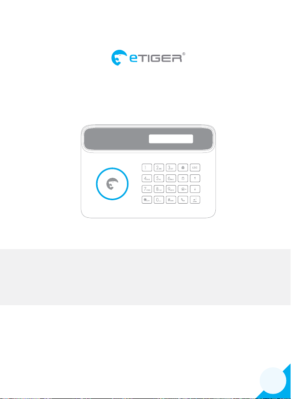
S4 Combo Secual / S4 Combo Vid Secual
Système d'alarme GSM et ligne xe
www.etiger.com
FR
Page 74

Caractéristiques
- Transmetteur GSM/RTC (ligne xe)
- Accepte jusqu'à 30 télécommandes, 50 accessoires sans l et 50 badges RFID
- Enregistrement de 5 numéros de téléphone, 5 numéros pour notications SMS et 2 numéros
CMS (pour les systèmes connectés à un centre de surveillance)
- Armement / désarmement par SMS, appel téléphonique, ou application (sur iOS ou Android)
- Désarmement par badge RFID
- Sirène 100 dB intégrée et fonction d'appel depuis la centrale
- Notications SMS en cas de panne et rétablissement de courant, et en cas de batterie faible
- Surveillance audio du site à distance
- Batteries de secours incluses (2 x 800 mAh, au lithium), permettant jusqu'à 8h en mode veille
Spécications
Nom du produit
S4 Combo Secual
SKU
S4-C
Alimentation de la centrale
Entrée : AC 110-240V / 50-60 Hz
Sortie : DC 12V / 800 mA
Fréquence GSM
850 / 900 / 1800 / 1900 MHz
Radio-fréquence
433 MHz (±75 KHz)
Courant (veille)
110 mA
Dans la boîte
Centrale S4 x1
Détecteurs de mouvement x2
Détecteurs d'ouverture de porte / fenêtre x2
Télécommandes x2
Badges RFID x2
Câble RTC x1
Dédoubleur RTC x1
Courant (fonctionnement)
340 mA
Batteries de secours
Lithium, 3.7 V / 800 mAh x 2 (BL-5B)
Sirène interne
100 dB
Boîtier
Plastique ABS
Conditions d'utilisation
Température : -10°C~55°C
Humidité : ≤ 80% (sans condensation)
Dimensions de la centrale
188 x 132 x 26 mm
Adaptateur secteur x1
Documentation x1
S4 Combo Vid Secual
+ Caméra IP x 1 (avec adaptateur secteur et
manuel d'utilisation)
Page 75
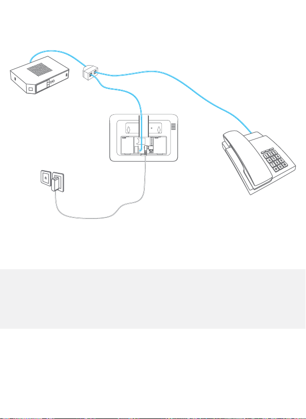
Démarrage rapide
Page 76
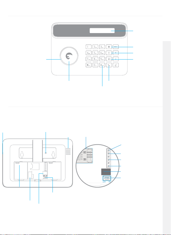
Design de la centrale (face)
VCC
Z1
GND
SP
GND
LOCK P1
Témoin lumineux
(armé / désarmé)
Écran LCD
Armer
Désarmer
Mode Maison
Design de la centrale (arrière)
Bouton
anti-arrachge
Interrupteur
Interface
d'alimentation
Micro
Compartiment à
batterie
Interface pour ligne
téléphonique
Lecteur de badge RFID
Haut-parleur
Emplacement carte SIM
SOS
Appel
Sortie pour
détecteurs laires
Détecteurs filaires
(zone 24h)
Sirène filaire 500 mA
Serrure électronique
Interface alimentation
Allumer / Éteindre
Accessoires Sécurité et dépannageDémarrage rapide Opérations sur la centrale Opérations SMS
4
Page 77
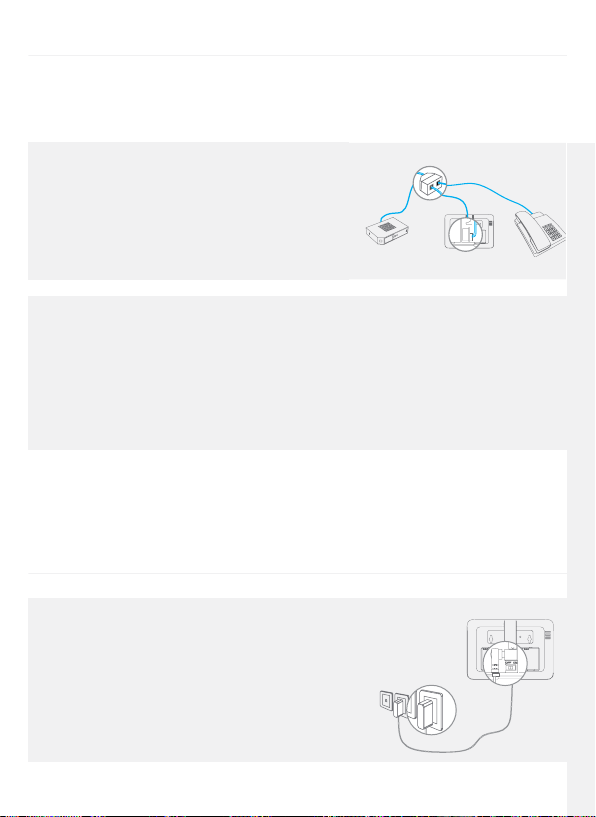
Brancher le système
La S4 Combo Secual possède un transmetteur GSM et RTC, qui permet à la centrale
de communiquer avec vous par carte SIM (module GSM), ou par le biais de votre ligne
téléphonique (module RTC).
a. Avec le module RTC (ligne xe)
Connectez la plus petite extrémité du câble téléphonique
(fournis) à l'interface pour ligne téléphonique située
dans le compartiment à batterie de votre centrale.
Connectez ensuite l'autre extrémité du câble
téléphonique à votre prise téléphonique (murale ou sur
votre box ADSL).
a. Avec le module GSM (carte SIM)
Ouvrez le compartiment à batterie au dos de la centrale et insérez-y une carte SIM.
Important
Avant d'utiliser la S4 Combo Secual en mode GSM, procurez-vous une carte SIM compatible
sur le réseau GSM 850 / 900 / 1800 / 1900 MHz. Nous vous recommendons de souscrire à
un abonnement avec SMS illimités et une heure d'appel. Pour plus d'informations, contactez
votre revendeur.
Important
Assurez-vous que la carte SIM n'est pas bloquée par un code PIN. Pour plus d'informations,
contactez votre revendeur.
Allumer le système
Accessoires Sécurité et dépannageDémarrage rapide Opérations sur la centrale Opérations SMS
1. Branchez l'adaptateur secteur à une prise.
2. Raccordez l'adaptateur secteur à l'interface d'alimentation
située dans le compartiment à batteries.
3. Positionnez l'interrupteur situé dans le compartiment à
batteries sur "ON".
5
Page 78

Fixer la centrale au mur
Avant de xer la centrale, assurez-vous que la réception du signal GSM est susante.
Fixez le support de montage au mur à l'aide de vis. Calez la centrale sur le support en vous
assurant que la centrale soit stable.
Premiers pas
Changer la langue du système
La langue de la centrale du S4 par défaut est l'anglais. Pour changer la langue du système,
référez-vous aux instructions page 12. "La langue de la centrale" correspond à la langue dans
laquelle vous recevez les notications SMS et à celle de l'écran LCD.
Choisir le module GSM / RTC
Référez-vous aux instructions page 11 de ce manuel pour désactiver le mode que vous ne
souhaitez pas utiliser :
Mode GSM uniquement (carte SIM requise, vendue séparément) : dénissez "ALARME LIGNE" sur "OFF"
Mode RTC uniquement (connexion à une ligne téléphonique requise) : dénissez "AUCUN SIGNAL
GSM" sur "OFF"
Par défaut, les modes GSM et RTC sont tous les deux activés.
Enregistrer un numéro de téléphone
Pour interagir avec la centrale par SMS, par appel téléphonique et/ou depuis l'application, au
moins un numéro de téléphone doit être enregistré dans la centrale. Pour ce faire, référez-vous aux
instructions page 10.
Armer / Désarmer le système
Le système d'alarme peut être armé ou désarmé depuis la centrale, par SMS, par appel téléphonique
ou depuis l'application.
Depuis la centrale : référez-vous aux instruc tions page 9 de ce ma nuel.
Par badge RFID (désarmement uniquement) : présentez le badge RFID devant le lecteur RFID
de la centrale.
Pour recevoir les notications par SMS à chaque fois que le système est désarmé par badge RFID, un
numéro pour notications SMS doit être enregistré dans la centrale (référez-vous aux instructions
page 10). Si vous avez enregistré plusieurs numéros pour notications SMS, seul le premier
numéro enregistré recevra les notications lors du désarmement par badge RFID.
Par SMS (en mode GSM uniquement) : pour armer votre système, envoyez “1” par SMS au
numéro de téléphone de la carte SIM dans votre centrale. Pour désarmer votre système,
envoyez “0” par SMS au numéro de téléphone de la carte SIM dans votre centrale.
Par application (en mode GSM uniquement) : cliquez sur “Armer” ou “Désarmer” pour armer
ou désarmer le système.
Accessoires Sécurité et dépannageDémarrage rapide Opérations sur la centrale Opérations SMS
6
Page 79

L'application est disponible sur l'App Store et Google Play (plus d'informations sur etiger.com).
Enregistrer des accessoires et badges RFID supplémentaires
1. Sur la centrale, tapez votre code admin puis appuyez sur “Enter ”
2. Entrez en mode de Connexion depuis le menu de la centrale :
"ACCESSOIRES" --> "DETECTEUR" , "BADGE RFID" ou "TELECOMMANDE" --> "AJOUTER"
Lorsque vous enregistrez un détecteur, il vous sera demandé de choisir le type de détecteur (det.
zone normal, det. zone maison, det. zone entrée, det. zone 24h). Plus d'informations page 10.
3. Dans les 30 secondes qui suivent, déclenchez l'accessoire que vous souhaitez enregistrer (pour
un badge RFID, présentez-le devant le lecteur RFID de la centrale). Vous entendez un bip :
l'enregistrement a bien été eectué.
Le code admin par défaut est 123456. Pour changer le code, référez-vous aux instructions page 11.
Si l'accessoire a déjà été enregistré, la centrale émet deux bips. Le premier détecteur enregistré
est assigné à la zone 1, le second détecteur enregistré est assigné à la zone 2, etc. Les zones 1 à 9
peuvent être renommées. Les zones 10 à 50 ne peuvent pas être renommées. Pour savoir comment
renommer les zones, reportez-vous aux instructions page 20 de ce manuel.
Appel abrégé
Sur la centrale, appuyez sur le bouton d'appel “ ” pendant 3 secondes : la centrale compose
le premier numéro de téléphone enregistré. Appuyez à nouveau sur le bouton d'appel “
pour raccrocher.
”
Appel mains-libres depuis la centrale
En utilisant le module RTC (ligne xe)
Sur la centrale, appuyez sur le bouton d'appel“ ”, tapez le numéro de téléphone que vous
souhaitez appeler puis appuyez sur “Enter”.
En utilisant le module GSM (carte SIM)
Sur la centrale, appuyez sur le bouton d'appel “
souhaitez appeler puis appuyez à nouveau sur le bouton d'appel “
”, tapez le numéro de téléphone que vous
”.
Remise à zéro
Éteignez la centrale. Appuyez et maintenez enfoncée la touche " " tout en allumant la centrale,
puis tapez "123456" sur le clavier de la centrale.
Les paramètres d'usine seront restaurés. Les numéros de téléphone et les accessoires
enregistrés dans la centrale seront supprimés de celle-ci.
Accessoires Sécurité et dépannageDémarrage rapide Opérations sur la centrale Opérations SMS
7
Page 80
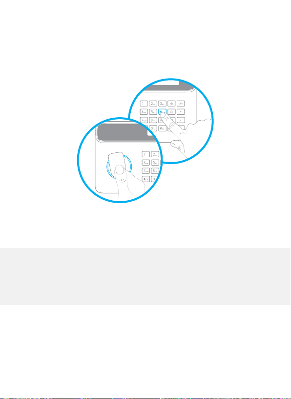
Opérations sur la centrale
Page 81
Armer le système
Appuyez sur la touche "Armer" de la
centrale "
système est armé.
Remarque
Si le délai d'entrée et de sortie est activé,
seuls les détecteurs dans la zone Délai seront
armés après le délai déni (référez-vous aux
instructions page 11 de ce manuel).
". La centrale émet un bip : le
Désarmer le système
Sur la centrale, tapez votre code utilisateur
et appuyez sur le bouton désarmer "
centrale émet deux bips : le système est
désarmé.
Code utilisateur par défaut : 1234
". La
Mode Maison
Sur la centrale, appuyez sur le bouton Mode
Maison " ". La centrale émet un bip : le
système est armé en Mode Maison.
Tous les détecteurs assignés à la zone
Normale sont armés. Les détecteurs
assignés à la zone Maison sont désarmés.
Pour plus d'informations sur la conguration
des zones, référez-vous aux instructions page
14 de ce manuel.
Conguration depuis la centrale
La centrale de votre système dispose d'un
écran LCD qui vous permet de naviguer
à travers le menu et de congurer votre
alarme.
Pour accéder au menu, tapez [votre code
admin + Enter] sur la centrale.
Code admin par défaut : 123456
Dans les tableaux sur les pages suivantes,
chaque colonne représente un menu ou
sous-menu. Chaque menu ou sous-menu
sera aché sur une des deux lignes de
l'écran LCD. Sur l'écran, le menu ou sousmenu dans lequel vous êtes est aché sur la
ligne du bas, tandis que le menu supérieur
est aché sur la ligne du haut.
Naviguez et choisissez le paramètre que
vous souhaitez modier avec les touches “ ”
ou “ ”, puis accédez au menu ou sous-menu
en appuyant sur “Enter”.
Comment utiliser le clavier
“ “ = supprimer
” = suivant
“
“
” = précédent
“Enter” = choisir / conrmer
“Esc” = annuler / précédent
Les tableaux sur les pages suivantes
répertorient toutes les fonctions
paramétrables depuis la centrale.
Accessoires Sécurité et dépannageDémarrage rapide Opérations sur la centrale Opérations SMS
Mode d'Urgence
Maintenez enfoncé le bouton SOS “#
pendant 3 secondes. L'alarme est alors
immédiatement déclenchée et la centrale
compose les numéros de téléphone enregistrés.
SOS
”
9
Page 82
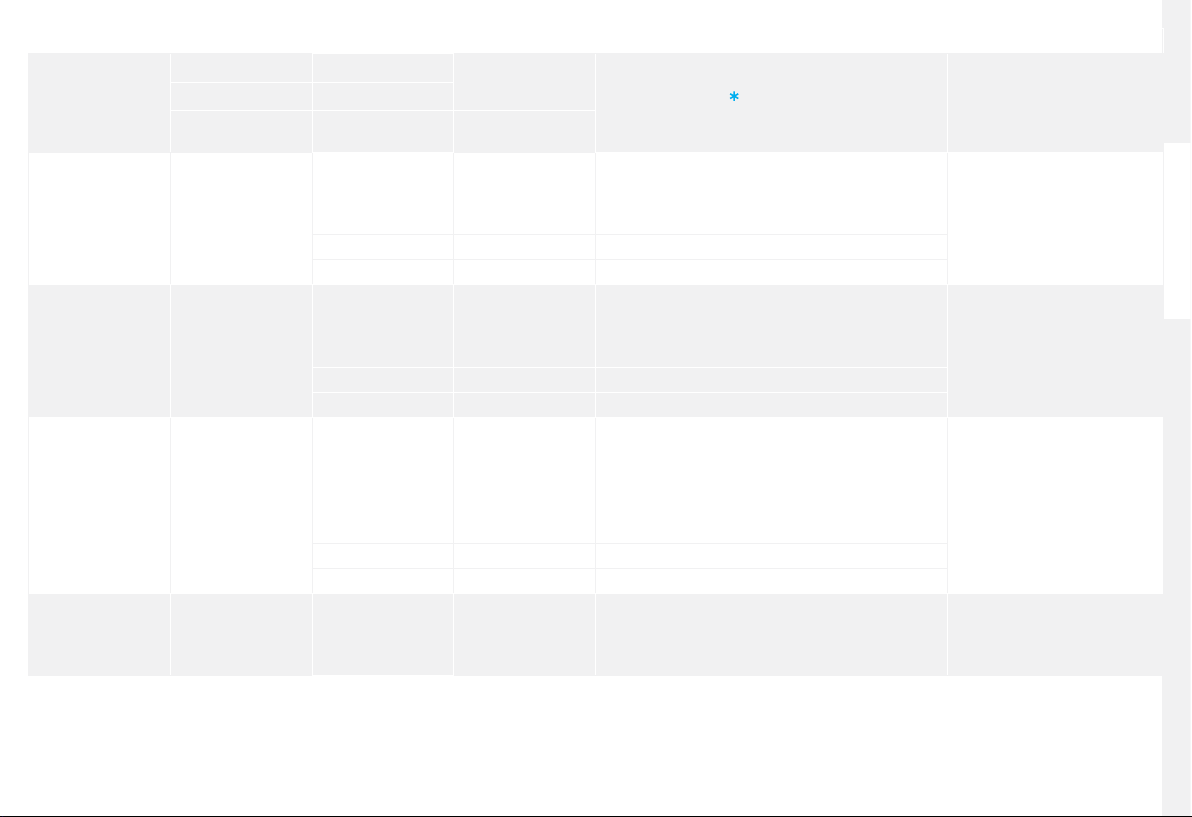
Menu principal Sous-menu 1 Sous-menu 2 Sous-menu 3 Commentaires Remarques
N° TEL 1~5
N° TELEPHONE
ACCESSOIRES
ACCESSOIRES BADGE RFID
ACCESSOIRES DETECTEUR
ACCESSOIRES MODE TEST
N° SMS 1~5
N° CMS 1~2
TELECOMMANDE
(et Clavier)
AJOUTER
TOUT SUPPRIMER 1=OUI 0=NON
SUPPRIMER UNE ENTREZ 0130 Sélectionnez la télécommande que vous souhaitez supprimer.
AJOUTER
TOUT SUPPRIMER 1=OUI 0=NON
SUPPRIMER UN ENTREZ 0150 Sélectionnez le badge RFID que vous souhaitez supprimer.
AJOUTER
TOUT SUPPRIMER 1=OUI 0=NON
SUPPRIMER UN ENTREZ 0150
DET. ZONE NORMAL
DET. ZONE MAISON
DET. ZONE ENTREE
DET. ZONE 24H
Choisissez le numéro de téléphone ou SMS que vous souhaitez
éditer, tapez le numéro de téléphone puis conrmez en appuyant sur
"Enter". Utilisez la touche "
5 numéros de téléphone, 5 numéros pour notications SMS et 2
numéros pour centre CMS peuvent être enregistrés dans la centrale.
L'écran ache “CONNECTEZ ACC 30” : appuyez sur une des touches
de la télécommande dans les 30 secondes suivantes (le décompte
est indiqué sur l'écran après "CONNECTEZ ACC", en secondes).
Vous entendez un bip, l'écran LCD ache “A JOUTE RC 01~30”: la
connexion a réussi.
L'écran LCD ache “CONNECTEZ ACC 30” : présentez le badge
RFID devant le lecteur RFID dans les 30 secondes qui suivent (le
décompte est indiqué sur l'écran après "CONNECTEZ ACC", en
secondes). Vous entendez un bip, l'écran LCD ache “AJOUTE RFID
01~50”, la connexion a réussi.
Sélectionnez le type de détecteur pour le détecteur que vous
souhaitez enregistrer (Normal, Maison, 24h, Délai), puis appuyez sur
“Enter” pour conrmer.
L'écran LCD ache “CONNECTEZ ACC 30” : déclenchez le détecteur
dans les 30 secondes qui suivent (le décompte es t indiqué sur
l'écran après "CONNECTEZ ACC", en secondes). Vous entendez un
bip, l'écran LCD ache “AJOUTE ZONE 01~50]”, la connexion a
réussi.
Déclenchez les détecteurs que vous avez préalablement enregistrés
dans la centrale. Vous entendez un bip, l'écran LCD ache les
signaux qui ont été émis par chaque détecteur. Assurez-vous que les
détecteurs déclenchés sont tous mentionnés sur l'écran. Appuyez
sur “Esc” pour quitter le mode test.
" pour eacer.
Si vous souhaitez dénir un numéro
pour centre CMS, référez-vous aux
instructions page 14 de ce manuel.
Pour plus d'informations sur la conguration des zones, référez-vous aux
instructions page 14.
Ce mode vous permet de tester
l'enregistrement de vos détecteurs dans
la centrale.
Accessoires Sécurité et dépannageDémarrage rapide Opérations sur la centrale Opérations SMS
10
Page 83
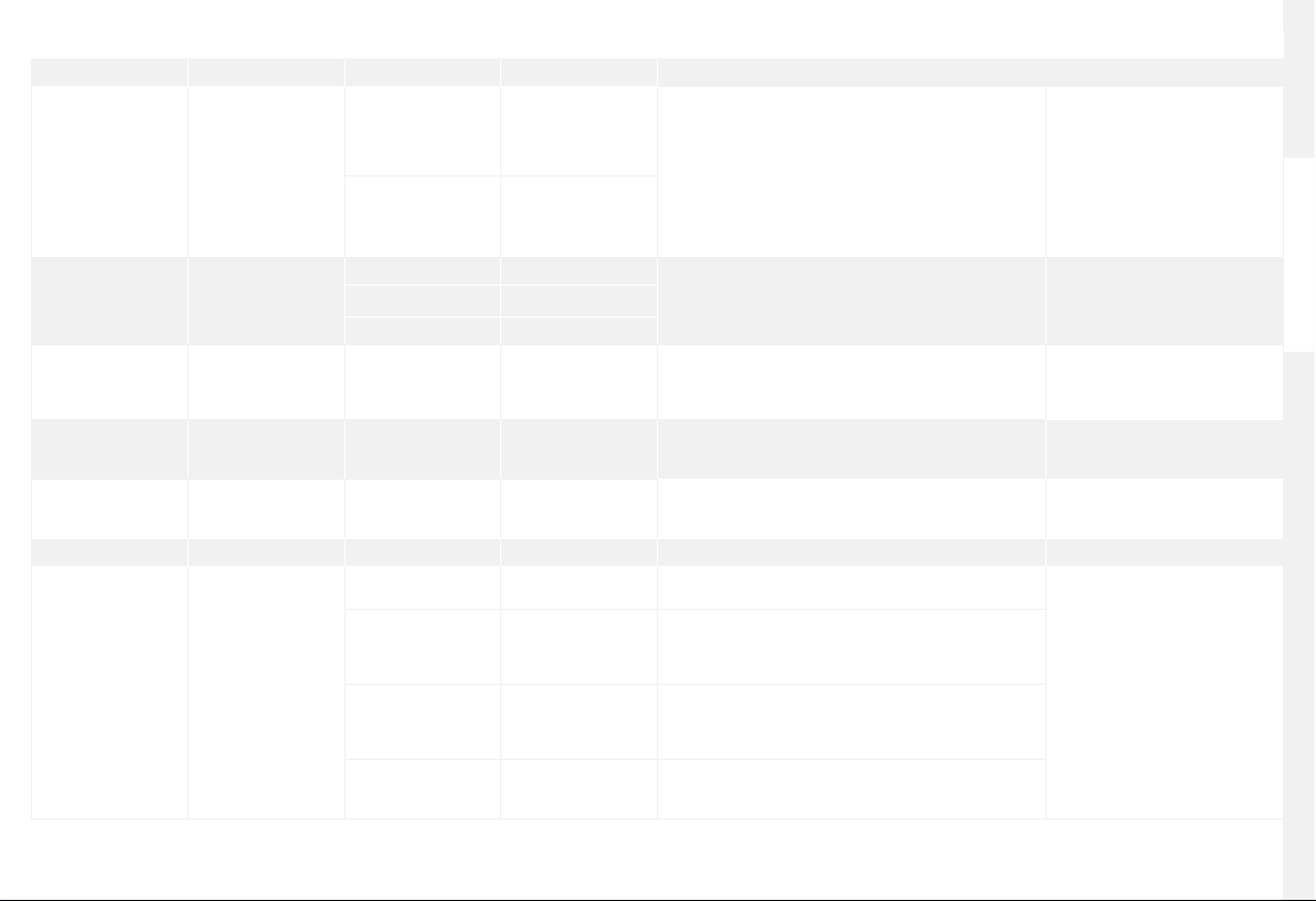
Menu principal Sous-menu 1 Sous-menu 2 Sous-menu 3 Commentaires Remarques
PARAMETRES DATE ET HEURE YYYYMMDD HEURE par exemple 20140620 14H30
Cette fonction peut être utilisée si vous ne souhaitez pas avoir de
DÉLAI ENTRÉE 000300
PARAMETRES DEL AI ENT/SORTIE
DÉLAI SORTIE 000300
TPS ARM AUTO <00:00>
PARAMETRES ARM/DESARM AUTO
PARAMETRES CONTROLE PAR TEL ON / OFF
PARAMETRES AL ARME LIGNE ON / OFF
PARAMETRES AUCUN SIGNAL GSM ON / OFF Notication en cas de défaut de signal GSM.
PARAMETRES SON TOUCHES ON / OFF Active ou désactive le son des touches du clavier de la centrale.
PARAMETRES CODE D'ACCES
TPS DESARM AUTO <00:00>
ON OU OFF?
CODE ADMIN 123456
CODE UTILISAT 1234
CODE CONTRAINTE 0000
CODE OUVERTURE 8888
télécommande ou de badge RFID sur vous. Lorsque vous armez
votre alarme, un bip est émis chaque seconde pour vous rappeler
de quitter les lieux. Le rythme des bips s'accélère au cours des 10
dernières secondes. Si une intrusion est détectée, l'alarme sera
retardée en fonction.
Le délai est calculé en secondes. Le délai d'entrée et de sortie peut
être déni de 0 à 300 secondes.
Vous pouvez paramétrer votre système pour que celui-ci s'arme et
se désarme automatiquement tous les jours à une heure dénie.
Le contrôle du système par appel téléphonique peut être activé ou
désactivé. Le contrôle par appel téléphonique vous permet d'armer
et de désarmer votre système, ainsi que de lancer une surveillance
audio.
Si cette fonction est activée, l'alarme sera déclenchée si votre
ligne téléphonique est coupée. Le premier numéro SMS reçoit une
notication par SMS (en mode GSM uniquement).
Votre code admin vous permet d'entrer dans le menu de la centrale
Code admin par défaut : 123456
Votre code utilisateur vous permet d'armer et de désarmer le
système depuis la centrale. C'est également votre code d'accès lors
du contrôle par appel téléphonique.
Code utilisateur par défaut : 1234
Si vous êtes contraint à désarmer le système de force, nous vous
recommendons de le désarmer en utilisant le code Contrainte. La
centrale compose alors les numéros de téléphone enregistrés.
Code Contrainte par défaut : 0000
Ce code vous permet d'ouvrir les serrures électroniques. Les
serrures doivent être connectées à l'interface [LOCK] dans le compartiment à batterie de la centrale.
Le délai d'entrée et de sortie aecte
uniquement les détecteurs assignés à la
zone Délai (cf. page 10).
Le Délai d'entrée vous donne le temps de
désarmer votre système sans déclencher
d'alarme.
Le Délai de sortie vous donne le temps
d'armer votre système et de quitter votre
domicile sans déclencher d'alarme.
Dénir l'armement et le désarmement
automatique à la même heure désactive la fonction.
Référez-vous aux instructions page 13
pour plus d'informations sur le contr ôle
du système par appel téléphonique.
Désactivez cette fonction si vous
souhaitez n'utiliser votre système qu'en
mode GSM.
Désactivez cette fonction si vous
souhaitez n'utiliser votre système qu'en
mode RTC.
Nous vous recommendons de changer
tous les codes avant d'utiliser votre
alarme pour la première fois, et de ne
jamais dévoiler vos codes.
Accessoires Sécurité et dépannageDémarrage rapide Opérations sur la centrale Opérations SMS
11
Page 84
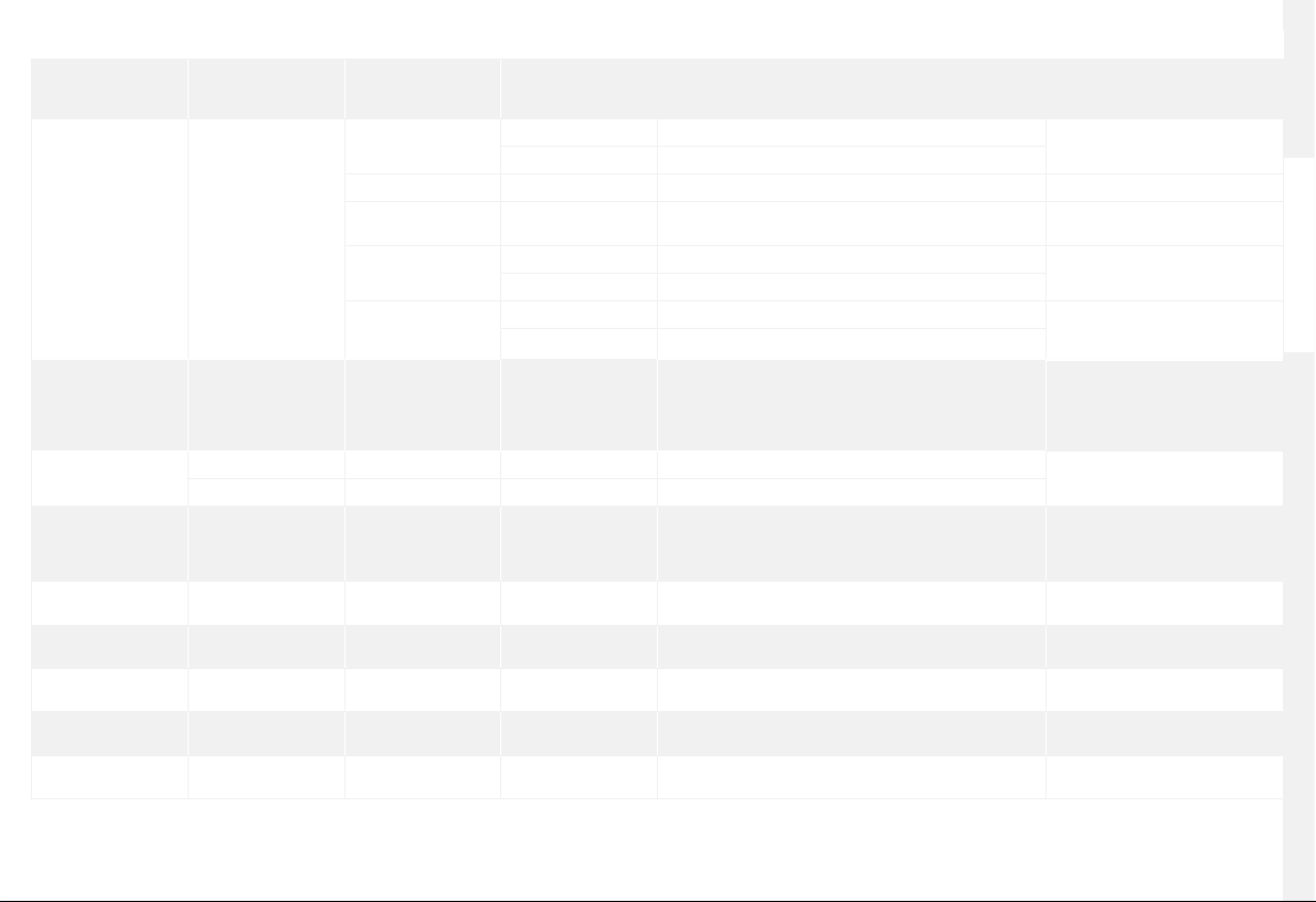
Menu principal Sous-menu 1 Sous-menu 2 Sous-menu 3 Commentaires Remarques
PARAMETRES TONALITES <09>
SIRENE FILAIRE
VOLUME SIRENE 010=MUET
PARAMETRES
PARAMETRES ID UTILISATEUR 4CHIFFRES:0000 Plus d'informations page 14
PARAMETRES
PARAMETRES REPE TITION D'APPEL <09>
PARAMETRES ECL AIRAGE ECRAN 030 S Appuyez sur “Enter” pour ajuster la durée d'éclairage de l'écran.
PARAMETRES L ANGUE Cette fonction permet de changer la langue du système.
PARAMETRES RESE T
PARAMETRES A PROPOS
HISTORIQUE - - -
PARAM. SIRENE
TELECHARGER ARM ON / OFF Notication d'armement par SMS
TELECHARGER DES. ON / OFF Notication de désarmement par SMS
DUREE SIRENE 3 MIN
SIRENE INTEGREE
SIRENE SANS FIL
A PROPOS
MOIS JJ AAAA
ON OU OFF?
SON ARM/DESARM
ON OU OFF?
SON ARM/DESARM
ON OU OFF? Sirène sans l correspond à une sirène
SON ARM/DESARM
Cette fonction vous permet de déterminer le nombre de fois que la
centrale sonne avant de prendre votre appel (lors du contrôle par appel
téléphonique).
La durée de retentissement de la sirène est calculée en minutes (3
minutes par défaut). Si la durée est dénie sur 0, la sirène ne sonnera pas.
Lorsque l'alarme est déclenchée, la centrale compose les numéros
enregistrés. Si vous ne désarmez pas l'alarme, la centrale réitère
l'appel (jusqu'à 9 fois). Cette fonction vous permet de dénir le
nombre de fois que la centrale tente de vous appeler.
Tous les paramètres seront remis à zéro. Tous les numéros de
téléphone et accessoires seront eacés.
Choisissez l'évènement sur lequel vous souhaitez en savoir plus,
puis appuyez sur “Enter”.
Sirene laire correspond à une sirène
branchée à la centrale.
Sirène intégrée correspond à la sirène
intégrée à la centrale.
enregistrée dans la centrale et connectée par fréquence radio.
Ces informations sont fournies par votre
centre CMS. Après avoir enregistré le code
utilisateur, le centre CMS sera en mesure
de déterminer votre localisation exacte en
fonction de votre numéro d'utilisateur.
Cette fonction est disponible uniquement en mode GSM (carte SIM requise)
La durée de l'éclairage peut être déni
de 0 à 300 secondes.
Les langues disponibles peuvent varier
selon les versions.
La centrale mémorise jusqu'à 100
évènements.
Accessoires Sécurité et dépannageDémarrage rapide Opérations sur la centrale Opérations SMS
12
Page 85
Contrôle par appel téléphonique
Cette fonction n'est disponible qu'après l'avoir activée depuis la centrale, comme expliqué en page
11.
Méthode 1
Lorsque l'alarme est déclenchée, la centrale compose les numéros de téléphone enregistrés.
Après avoir décroché, vous pouvez contrôler la centrale à distance en suivant les instructions
décrites dans le tableau ci-dessous.
Méthode 2
1. Sur votre téléphone, composez le numéro de téléphone de la carte SIM dans votre centrale
ou le numéro de ligne xe à laquelle la centrale est connectée. Puis laissez-vous guider par les
instructions vocales pour entrer votre code d'accès.
2. Tapez votre code d'accès (code utilisateur), puis appuyez sur la touche ”#”.
3. Une voix vous donne les options disponibles.
4. Le tableau ci-dessous récapitule les diérentes options qui s'orent à vous.
Remarque
L'appel est interrompu automatiquement après 30 secondes sans activité de votre part.
Tableau des commandes
Commande Fonction Commentaire
Touche “1“ Arme le système
- Désarme le système et arrête la sirène
Touche “0“
- Met n à la surveillance audio sans
raccrocher
- Met n à la conversation sans raccrocher
Indication vocale “System armed”
(Système armé)
Indication vocale “System disarmed”
(Système désarmé)
Accessoires Sécurité et dépannageDémarrage rapide Opérations sur la centrale Opérations SMS
“ Surveillance audio
Touche “
Touche “3“ Appel avec la centrale -
Touche “6“ Arrête la sirène -
Touche “9“ Déclenche la sirène -
Touche “#“
- Désarme le système et arrête la sirène
- Sortie du contrôle par appel
téléphonique
Appuyez sur la touche “
votre téléphone pour prolonger la
surveillance audio*
Cette fonction peut être obtenue
en raccrochant
” de
13
Page 86

*En mode GSM, la surveillance audio est illimitée dans le temps.
En mode RTC (branché à votre ligne xe), la surveillance audio est limitée à 80 secondes. Pour
prolonger la durée de la surveillance, appuyez sur la touche “ ” de votre téléphone avant la
n des 80 secondes.
Conguration des zones
Chaque détecteur peut être assigné à 4 catégories de zones : zone Maison, zone Délai, zone Normale
et zone 24h. Pour assigner un détecteur à une zone, suivez les instructions page 10 (la zo ne est
assignée au moment de l'enregistrement de l'accessoire dans la centrale).
Zone Normale
Quand le système est armé, si un détecteur est déclenché, la sirène retentit. Quand le système
est désarmé, les détecteurs ne déclenchent pas d'alarme.
Zone 24h
Que le système soit armé ou désarmé, les détecteurs assignés à la zone 24h déclenchent une
alarme. Il est recommandé d'assigner les détecteurs de fumée et les détecteurs de gaz à la zone 24h.
Zone Délai
Un délai à l'entrée et un délai à la sortie peuvent être dénis. Dans ce cas, les détecteurs
assignés à la zone Délai ne peuvent déclencher une alarme qu'après le délai déni.
Par exemple, si vous assignez un détecteur de mouvement à la zone Délai et que vous
paramétrez 30 secondes de délai d'entrée, le détecteur de mouvement ne déclenchera
pas d'alarme pendant les 30 secondes qui suivent votre entrée chez vous : vous pouvez
ainsi rentrer chez vous et désarmer le système depuis la centrale sans déclencher d'alarme.
Reportez-vous aux instructions page 10 pour plus d'informations. Il est recommandé
d'assigner les détecteurs situés dans votre entrée à la zone Délai.
Zone Maison
Lorsque le système est armé en Mode Maison, les détecteurs assignés à la zone Maison ne
déclenchent pas d'alarme. Il est recommandé d'assigner les détecteurs de mouvement à la zone
Mode Maison pour que vous puissiez circuler librement chez vous même lorsque le système est
armé en Mode Maison, sans déclencher d'alarme.
Connecter à un centre CMS
Ignorez cette étape si votre système n'est pas relié à un centre de surveillance (CMS). Si vous
êtes relié à un centre de surveillance, votre centrale transfère automatiquement vos données
d'utilisateur au centre de surveillance en cas d'intrusion.
Accessoires Sécurité et dépannageDémarrage rapide Opérations sur la centrale Opérations SMS
14
Page 87
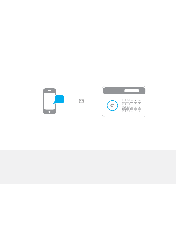
...
Opérations SMS
Page 88
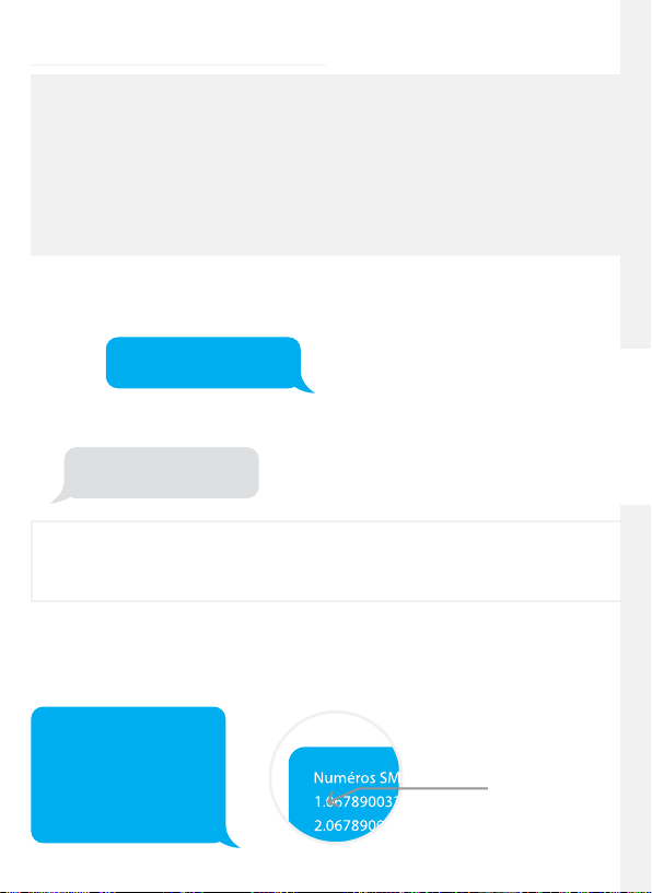
Opérations SMS
IMPORTANT : AVANT D'UTILISER POUR LA PREMIÈRE FOIS
INSÉREZ UNE CARTE SIM DANS LA CENTRALE.
ASSUREZVOUS QUE LA CARTE SIM NE SOIT PAS PROTÉGÉE PAR UN CODE PIN.
ENREGISTREZ UN NUMÉRO DANS LA CENTRALE DEPUIS LA CENTRALE.
Seuls les numéros enregistrés peuvent contrôler et congurer le système. Référez-vous aux
instructions page 10)
Chaque opération SMS présentée dans ce manuel sera illustrée comme suit :
Vous envoyez :
La bulle bleue correspond au premier SMS
Commande SMS
La centrale répond :
Réponse de la centrale
que vous envoyez.
La bulle grise correspond à la réponse
envoyée par la centrale.
Les bulles qui font suite correspondent au
dialogue entre vous et la centrale (vos SMS
en bleu, SMS envoyés par la centrale en gris)
Par défaut, le système est en anglais. Pour changer la langue du système, reportez-vous
aux instructions page 22.
Important
Lorsque vous répondez à la centrale par SMS, assurez-vous de ne pas insérer d'espace après
les ponctuations "." et ":". Par exemple, pour enregistrer les numéros SMS, votre SMS doit être
formaté comme suit :
Numéros SMS:
1.067890033
2.067890022
3.067890011
4.067890000
5.
Pas d'espace après "1."
Accessoires Sécurité et dépannageDémarrage rapide Opérations sur la centrale Opérations SMS
16
Page 89
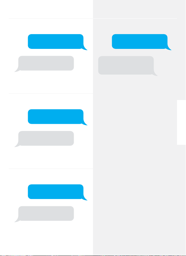
Désarmer le système
État du système
Envoyez :
0
Système désarmé
Armer le système
Envoyez :
1
Système armé
Mode Maison
Envoyez :
2
Envoyez :
00
Système:désarmé
Alimentation secteur:oui
Remarque
Les valeurs indiquées ci-dessus sont
susceptibles de changer selon les
paramètres de votre système.
Accessoires Sécurité et dépannageDémarrage rapide Opérations sur la centrale Opérations SMS
Système en Mode Maison
17
Page 90

Enregistrer les numéros de
téléphone
Enregistrer les numéros de
téléphone pour notications SMS
Envoyez :
5
Numéros de téléphone:
1.
2.
3.
4.
5.
Copiez, collez, puis éditez
(sensible à la casse) :
Numéros de téléphone:
1.067890033
2.067890022
3.067890011
4.067890000
5.
Ok
Envoyez :
6
Numéros SMS:
1.
2.
3.
4.
5.
Copiez, collez, puis éditez
(sensible à la casse) :
Numéros SMS:
1.067890033
2.067890022
3.067890011
4.067890000
5.
Ok
Remarque
Le premier numéro SMS enregistré recevra les
notications SMS à chaque fois que le système
sera désarmé par badge RFID. Pour recevoir
ces notications, les badges RFID doivent avoir
été renommés. Jusqu'à 4 badges peuvent être
renommés ; un numéro sera attribué aux autres
badges selon leur ordre d'enregistrement dans
la centrale. Référez-vous aux instructions page
10 pour en savoir plus sur l'enregistrement
des badges RFID.
Accessoires Sécurité et dépannageDémarrage rapide Opérations sur la centrale Opérations SMS
18
Page 91
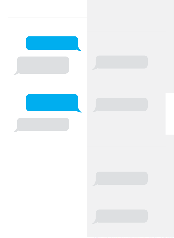
Renommer les zones
Envoyez "91~99". Par exemple, pour la zone
1, envoyez :
Alerte SMS batterie d'accessoire
faible
(disponible pour les accessoires tels que les
détecteurs de mouvement)
91
Noms des zones:
1.
Copiez, collez, puis éditez
(sensible à la casse) :
Noms des zones:
1.Entrance door sensor
Ok
Remarque
Les zones 1 à 9 peuvent être renommées. Le
nom de chaque zone ne doit pas comporter
plus de 30 caractères. Les zones 10 à 50 ne
peuvent être renommées.
Pour les accessoires assignés à des zones
ayant été renommées, un SMS sera envoyé
au format “nom de la zone + Batterie faible”.
Chambre Batterie faible
Pour les accessoires assignés à des zones
n’ayant pas été renommées, un SMS sera
envoyé au format “N° de la zone + Batterie
faible”.
Zone 10 Batterie faible
Alerte SMS tentative d’arrachage
d’un accessoire
(disponible pour les accessoires tels que les
détecteurs de mouvement)
Pour les accessoires assignés à des zones
ayant été renommées, un SMS sera envoyé au
format “nom de la zone + Sabotage”.
Chambre Sabotage
Pour les accessoires assignés à des zones
n’ayant pas été renommées, un SMS sera
envoyé au format “N° de la zone + Sabotage”.
Accessoires Sécurité et dépannageDémarrage rapide Opérations sur la centrale Opérations SMS
Zone 10 Sabotage
19
Page 92

Renommer les badges RFID
Délai d'entrée et de sortie
Envoyez :
10
Renommer les badges RFID:
1.
2.
3.
4.
Copiez, collez, puis éditez
(sensible à la casse) :
Renommer les badges RFID:
1. Tom
2. Nurse
3. Nancy
4. David
Ok
Remarque
Le premier numéro SMS enregistré recevra les
notications SMS à chaque fois que le système
sera désarmé par badge RFID. Pour recevoir
ces notications, les badges RFID doivent avoir
été renommés. Jusqu'à 4 badges peuvent être
renommés ; un numéro sera attribué aux autres
badges selon leur ordre d'enregistrement dans
la centrale. Référez-vous aux instructions page
10 pour en savoir plus sur l'enregistrement
des badges RFID.
Envoyez :
11
Délai d'entrée (0-300 sec):0
Délai de sortie (0-300 sec):0
Copiez, collez, puis éditez
(sensible à la casse) :
Délai d'entrée (0-300 sec):10
Délai de sortie (0-300 sec):10
Ok
Remarque
Cette fonction aecte uniquement les
détecteurs assignés à la zone Délai. Référezvous aux instructions page 10 pour savoir
comment assigner un détecteur à la zone
Délai.
Cette fonction peut être utilisée si vous ne
souhaitez pas avoir de télécommande ou de
badge RFID avec vous.
Lorsque vous armez le système, le système
s'arme après le délai déni. Lorsque vous
désarmez le système, le système se désarme
après le délai déni.
Lorsque le système est armé, vous entendez
un bip par seconde pour vous rappeler
de quitter les lieux. Le rythme s'accélère
pendant les 10 dernières secondes. Si une
intrusion est détectée, l'alarme est retardée
en fonction du délai.
Accessoires Sécurité et dépannageDémarrage rapide Opérations sur la centrale Opérations SMS
20
Page 93
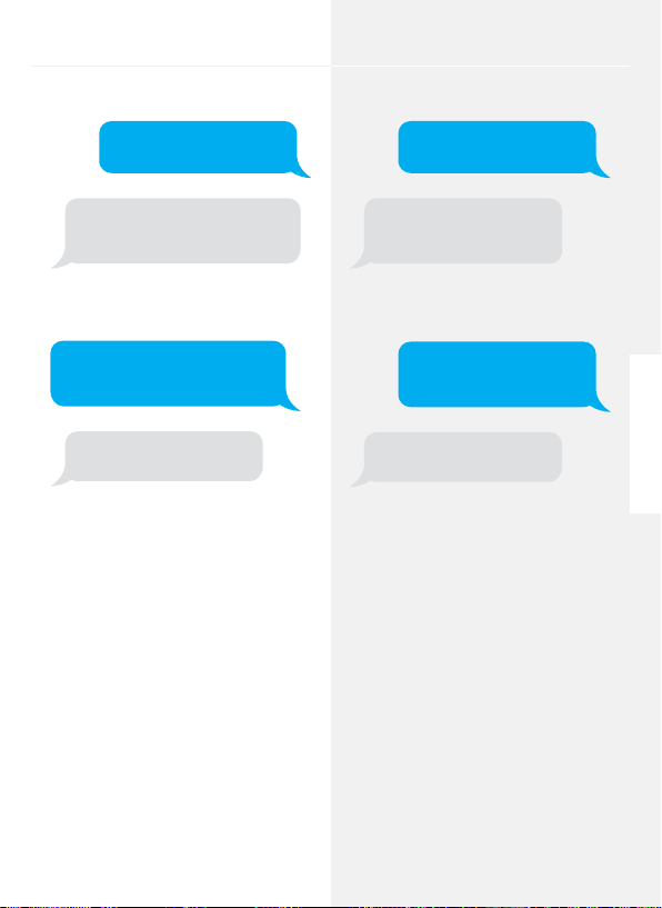
Volume et durée de la sirène
Changer le code
Envoyez :
12
Volume de la sirène (0=muet,1=fort):1
Durée de la sirène (1-9 min):5
Copiez, collez, puis éditez
(sensible à la casse) :
Volume de la sirène (0=muet,1=fort):0
Durée de la sirène (1-9 min):8
Ok
Envoyez :
13
Code de désarmement (4 chires):
1234
Copiez, collez, puis éditez
(sensible à la casse) :
Code de désarmement (4 chires):
8888
Ok
Accessoires Sécurité et dépannageDémarrage rapide Opérations sur la centrale Opérations SMS
21
Page 94
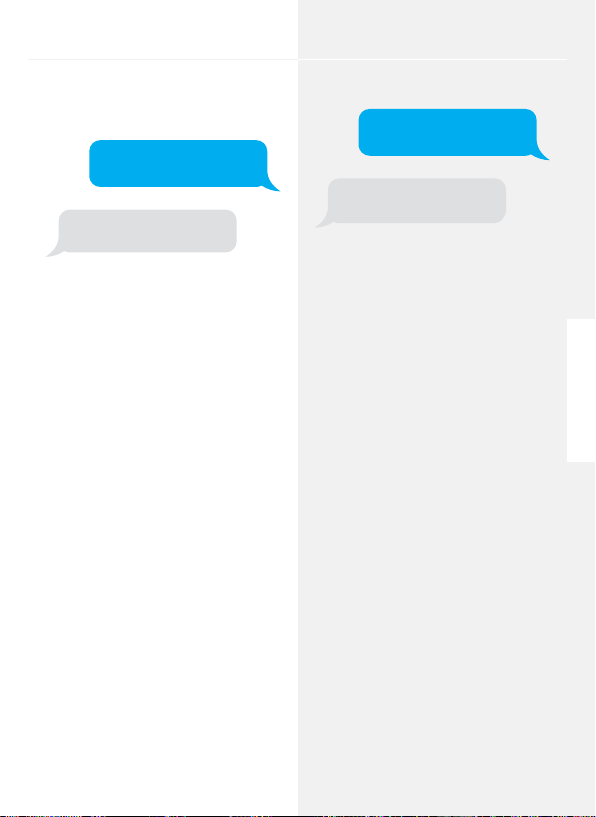
Changer la langue
Restaurer les paramètres d'usine
Envoyez le code correspondant à la langue
que vous souhaitez dénir. Par exemple,
pour le français, envoyez “0002”.
0001
Ok
Le tableau ci-dessous reprend les codes
pour chaque langue disponible
0001 Anglais
0002 Français
0003 Russe
0004 Danois
0005 Néerlandais
0006 Italien
0007 Suédois
Les langues disponibles peuvent varier
selon la version de votre produit.
0008 Allemand
0009 Espagnol
0010 Finnois
0011 Norvégien
0012 Arabe
0013 Farsi
Envoyez :
0000
Ok
Les paramètres d'usine seront restaurés. Les
numéros de téléphone et les accessoires
enregistrés dans la centrale seront
supprimés de celle-ci.
Remarque
Seuls les numéros enregistrés peuvent
restaurer les paramètres d'usine par SMS.
Accessoires Sécurité et dépannageDémarrage rapide Opérations sur la centrale Opérations SMS
22
Page 95
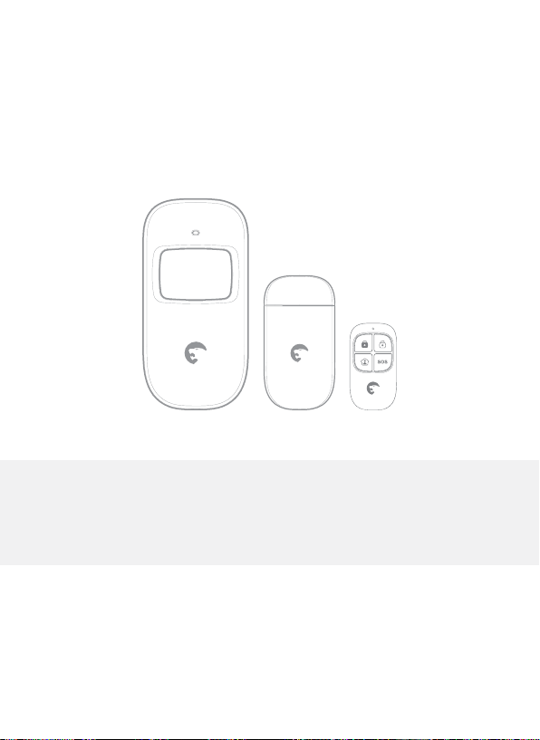
Accessoires
Page 96
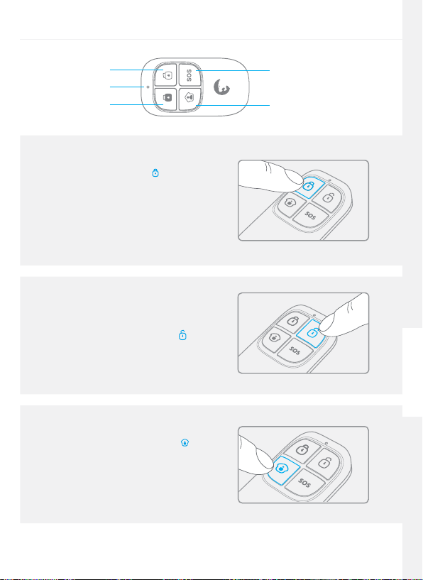
Télécommande
Désarmer
Témoin lumineux
Armer
Armer le système
Appuyez sur la touche Armer " ". Le témoin
lumineux s'allume (la centrale émet un bip) :
le système est armé.
Si une intrusion est détectée, la sirène sonne.
(La sirène s'éteint après 3 minutes par défaut.)
Pendant ce temps, la centrale compose les
numéros de téléphone enregistrés.
Désarmer le système
Appuyez sur la touche Désarmer " ". Le
témoin lumineux s'éteint (la centrale émet
deux bips). Le système est désarmé.
Mode Maison
Appuyez sur la touche Mode Maison " ". L e
témoin lumineux de la centrale est allumé. Tous
les détecteurs sont armés sauf ceux assignés à
la zone Mode Maison. Les détecteurs assignés
à la zone Mode Maison sont désactivés pour
éviter de déclencher une alarme lorsque vous
êtes chez vous.
SOS
Mode Maison
Accessoires Sécurité et dépannageDémarrage rapide Opérations sur la centrale Opérations SMS
24
Page 97
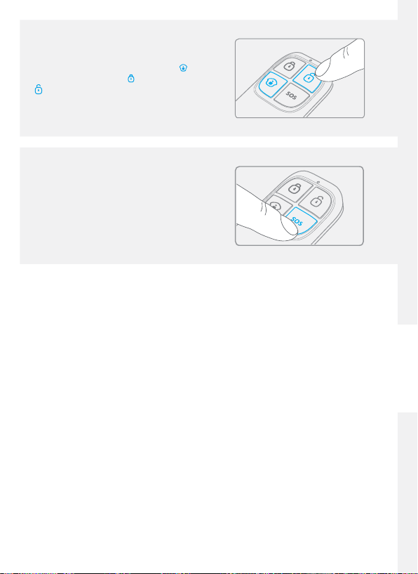
Mode Silencieux
Appuyez sur la touche Mode Maison " "
puis sur la touche Armer " " (ou Désarmer
") immédiatement après. Dans ce cas, la
"
centrale n'émet pas de son lorsque vous
armez ou désarmez votre système.
Mode d'urgence
Que le système soit armé ou désarmé, l'alarme
est déclenchée lorsque vous appuyez sur la
touche "SOS" de la télécommande.
La centrale envoie alors une notication par
SMS ("RC-01 SOS", 01 désignant le numéro de
la télécommande) et compose les numéros
de téléphone enregistrés.
Enregistrer la télécommande dans la centrale
Référez-vous aux instructions page 10 ("TELECOMMANDE").
Pour vous assurer que l'enregistrement a bien été eectué, référez-vous aux instructions sur le
mode test dans le tableau page 10.
Spécications
Alimentation
DC 3V (pile CR2025 x1)
Courant (veille)
10 uA
Courant (fonctionnement)
≤7 mA
Distance de transmission
≤ 80 m (sans obstacle)
Radio-fréquence
433 MHz (±75 KHz)
Boîtier
Plastique ABS
Conditions d'opération
Température : -10°C ~ +55°C
Humidité relative : ≤80%
(sans condensation)
Dimensions
57 x 31 x 11 mm
Accessoires Sécurité et dépannageDémarrage rapide Opérations sur la centrale Opérations SMS
25
Page 98
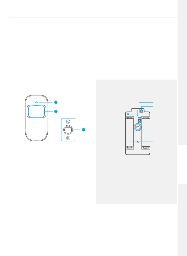
Détecteur de mouvement sans l
Caractéristiques
Le ES-D1A est un détecteur de mouvement haute performance. Grâce à sa puce de contrôle
infrarouge double coeur à logique oue numérique et à analyse intelligente identiant
ecacement les signaux d’interférence à partir des signaux de mouvements corporels, ce
détecteur réduit le risque de fausses alertes.
Grâce à ses technologies de compensation automatique de la température et anti-turbulence,
il s’adapte facilement aux variations environnementales.
Design
1. Témoin lumineux
2. Fenêtre de détection
3. Support
1
2
Circuit imprimé
Témoin lumineux
Antenne
3
Détecteur infrarouge
Détecte les rayons infrarouges émis par
les mouvements humains. Ne pas toucher
la surface. Maintenir propre.
Bouton anti-arrachage
Lorsque le système est armé, ce dispositif
déclenche l’alarme si le boîtier du
détecteur est ouvert.
Conguration de
la zone
Bouton
anti-arrachage
Détecteur
infrarouge
AA 1.5V LR6
Indications LED
Clignote continuellement : auto-test
Clignote une fois : intrusion détectée
Clignote deux fois : auto-test terminé ; passe en état de marche.
Clignote une fois toutes les 3 secondes : les piles doivent être remplacées (si le détecteur est
inscrit à la centrale d’alarme, vous recevrez une notication par SMS).
Accessoires Sécurité et dépannageDémarrage rapide Opérations sur la centrale Opérations SMS
26
Page 99
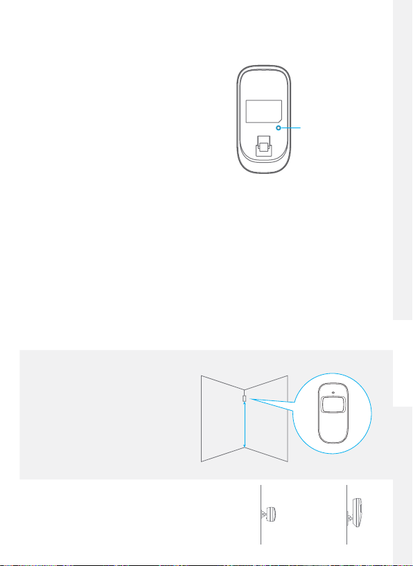
Utilisation
Ouvrez le boîtier et retirez la languette d’activation des piles. L’auto-test se lance pendant une
minute.
En fonctionnement, si le détecteur est
déclenché plus de 2 fois en 3 minutes, il
passe automatiquement en mode veille
pour économiser l’énergie. En l'absence de
détection durant ces 3 minutes, le détecteur
retourne en mode de fonctionnement
normal.
Connexion
Enregistrer le détecteur dans la centrale
Depuis le menu de la centrale, atteignez "AJOUTER" (sous "DETECTEUR") puis sélectionnez le
type de détecteur. Au cours des 30 secondes suivantes, appuyez sur le bouton Connexion au
dos du détecteur ou déclenchez celui-ci (en passant devant) pour l'enregistrer dans la centrale.
Pour vous assurer que l'enregistrement a bien été eectué, référez-vous aux instructions sur le
mode test dans le tableau page 10.
Installation
Évitez de xer le détecteur près des fenêtres, climatisations, chauages, refrigérateurs, fours ou
tout autre endroit soumis à des changements rapides de température, ou dans des endroits
où l’air circule fréquemment.
Si deux détecteurs sont installés dans le même champ de détection, ajustez leur emplacement
pour éviter les interférences et les fausses alarmes.
Haut
Fixez le support sur un mur à l’aide
de vis et montez le détecteur sur le
support. Ajustez le support pour
changer l’angle et la distance de
détection. Il est recommandé de
xer le détecteur à 2,2 m du sol.
2.2 m
Sol
Bas
Accessoires Sécurité et dépannageDémarrage rapide Opérations sur la centrale Opérations SMS
Le détecteur est plus sensible aux
mouvements horizontaux qu’aux
mouvements verticaux.
Vue de dessus
Vue de
côté
27
Page 100
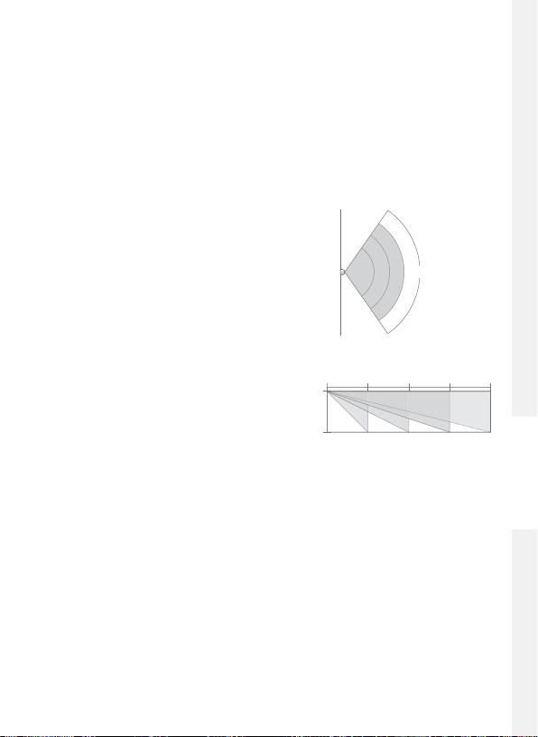
Test
A. Après la minute d’auto-test, appuyez sur le bouton de test, marchez dans le champ de
détection et observez le témoin lumineux pour vous assurer que le détecteur fonctionne
correctement.
B. Le témoin lumineux clignote une fois lorsqu’un mouvement est détecté.
C. Ajustez l’angle du détecteur pour obtenir les meilleures performances de détection.
Spécications
Alimentation
DC 3V (Piles AA 1.5V LR6 x 2)
Courant (veille)
≤ 30 uA
Courant (fonctionnement)
≤ 15 mA
Champ de détection
8 m / 110°
Distance de transmission
≤ 80 m (sans obstacle)
Radio-fréquence
433 MHz (±75 KHz)
Boîtier
Plastique ABS
Conditions d'opération
Température : -10°C ~ +55°C
Humidité relative : ≤80%
(sans condensation)
Dimensions du détecteur
107 x 53 x 32 mm
Dimensions du support
52 x 30 x 26.5 mm
Champ de détection
110°
Vue de dessus
0m 2m 4m 6m 8m
2m
0m
Vue de côté
Accessoires Sécurité et dépannageDémarrage rapide Opérations sur la centrale Opérations SMS
28
 Loading...