

Page 1
www.eger.com
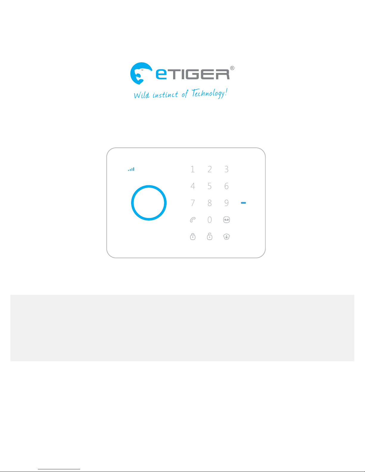
S3 Sim Secual
Alarm system with GSM transmier
Page 2
2 3
Features
- ARM CPU + Auror CPU
- GSM frequency: 850 / 900 / 1800 / 1900 MHz, suits all phones
- Supports up to 10 remote controls, 50 wireless accessories and 50 RFID tags
- Radio-frequency security of the accessories: more than one million code combinations
- Built-in siren (110dB) and call function from the panel
- Arm / disarm the system by SMS, phone call, or application (on iOS or Android)
- Stores up to 5 phone numbers, 1 speed dial phone number and 1 SMS number for RFID tag
notications
- Grid failure SMS alert
- Accessory low-battery SMS alert
- Built-in 800 mAh lithium batteries (5h battery life in standby mode)
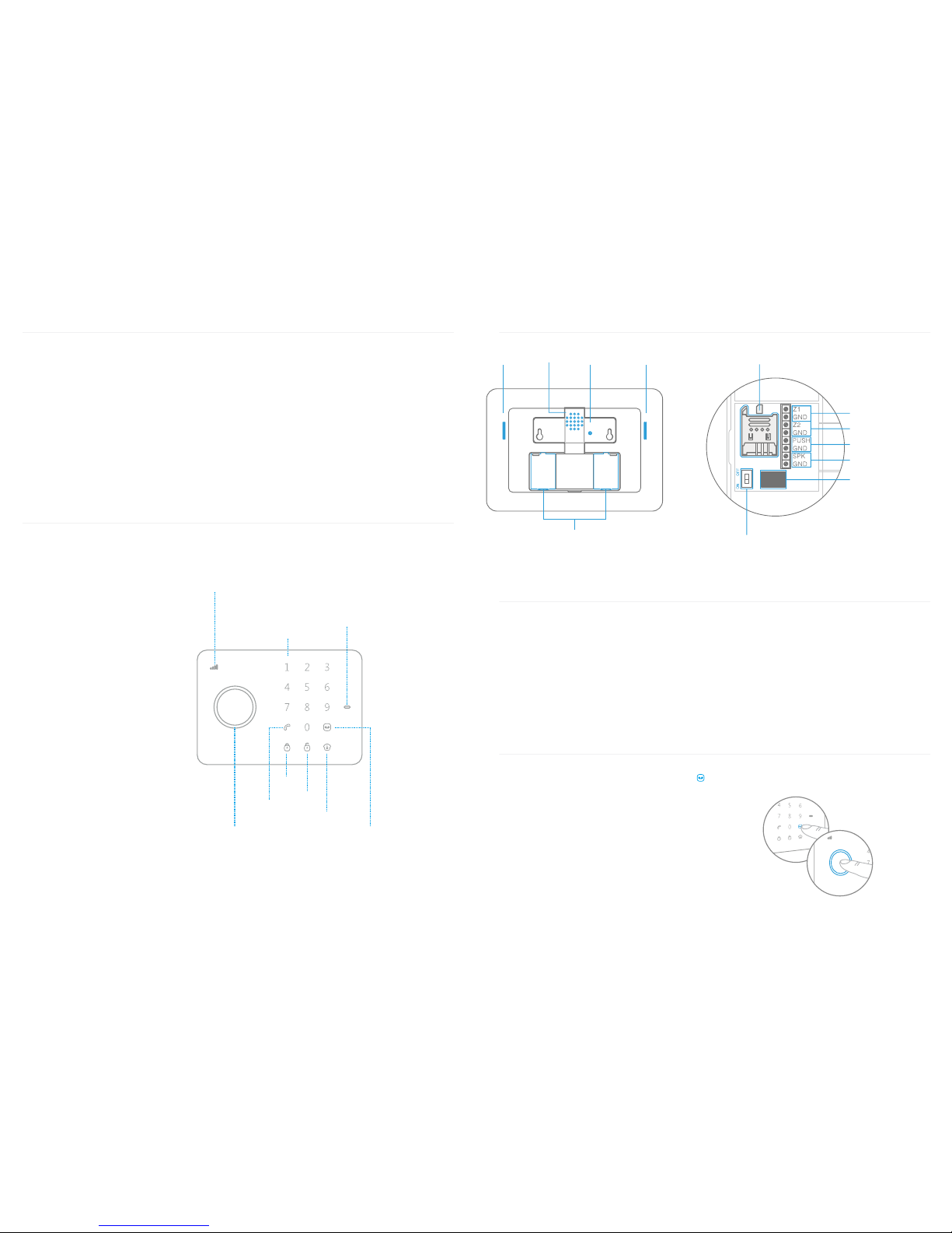
Control Panel Layout (Front)
GSM Signal Indicator
Searching GSM network: Blinks once every second
GSM signal is normal: Blinks once every two seconds
Touch Keypad
Status Indicator
Record Voice Memo /
Connect Buon
Stay Arm (Home Mode)
RFID player /
Play Voice Memo
Call
Arm
Disarm
Control Panel Layout (Back)
MIC
Siren / Speaker Tamper Switch
Loudspeaker
Back-up Baeries
SIM Card Slot
Power On/O
Input for Wired Sensors
(24-hour zone)
Input for Wired Sensors
(normal zone)
Adapter Interface
Output for Wired Siren 500mA
Output for Electronic Lock
Box Content
S3 Panel x1
AC Adapter x1
PIR Motion Detector x2
Door / Window Contact Detector x2
Remote Control x2
RFID tag x2
Documentation x1
Record / Play Voice Memo
Long press the Record Voice Memo button {
}
to record a 10-second voice message. The voice
message can also be recorded by sending an
SMS to the system, as explained in page 7 of
this manual. The Play Voice Memo Button blinks
when a message has been recorded.
Touch the centrer of the circle on the control
panel to listen to the voice memo. The LED
indicator turns o when the voice memo is
being played. Touch it again to replay the
memo.
Page 3
54
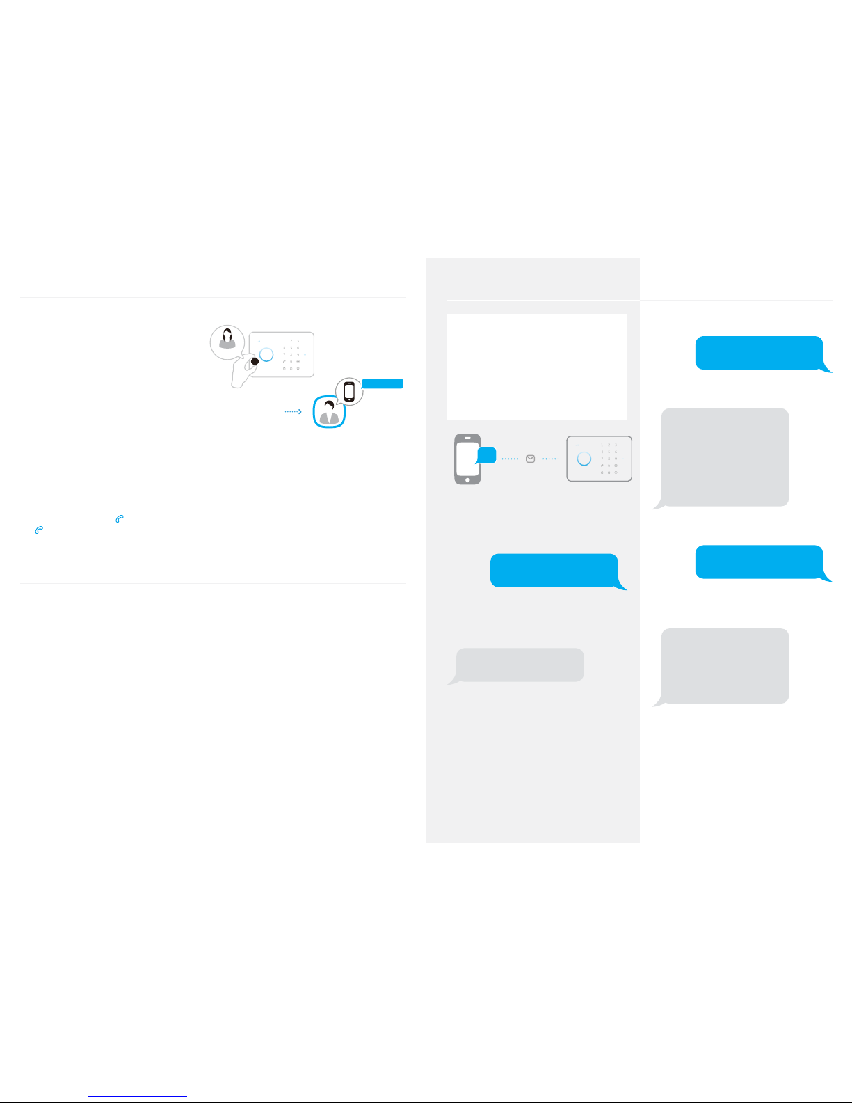
RFID Tag
The RFID tag can disarm the system and
unlock the electronic door (if connected to a
wireless keyboard). You can rename RFID tags
and store a mobile phone number that will
receive an SMS notication when the system
is disarmed with a RFID tag.
Note
To start receiving an SMS notication when
the system is disarmed by RFID tag, you must
store an SMS number and rename the RFID
tags (up to 4 RFID tags can be renamed).
Nancy
Mom
Administrator
Nancy came home
Speed Dial
Press the Call Button { }: the panel auto-dials the pre-stored phone number. Press the Call Button
{ } to end the call. The LED turns o after the call.
Phone Call
Dial a phone number and press the Call Button to start the call. Press the Call Button to nish the
call.
Electronic Lock
When you disarm the system, the output signal of the panel opens the electronic lock
automatically.
SMS Operations
Important
Insert a SIM card in the control panel
before starting SMS operations.
Make sure the SIM card does not
request any PIN code.
...
Each SMS operation included in this user
manual will be illustrated as follows:
You send:
SMS Command
The rst blue speech bubble is the SMS
command sent by the user.
The control panel replies:
Control panel’s reply
The rst grey speech bubble is the reply sent by
the control panel.
The speech bubbles that follow are the
dialogue between the user and the control
panel (SMS sent by the user are in blue, SMS
sent by the control panel are in grey).
The system is in English as per default
setting. To change the system’s language,
refer to page 13.
Request the Menu
Send:
?
The system sends the rst part of the menu:
‘0’ Disarm
‘1’ Arm
‘2’ Home mode
‘3’ Two-way talk
‘4’ Call-back voice memo
‘00’ Settings inquiry
‘??’ Store phone and SMS No
Send:
??
The system sends the second part of the
menu:
‘5’ Store phone No.
‘6’ Store alarm SMS No.
‘7’ Store SMS No. for RFID tags
‘8’ Store speed dial phone No.
‘???’ System setups
Page 4

6 7
Send:
???
The system sends the third part of the menu:
‘91~99’ Zone name‘
‘10’ RFID tags SMS notice
‘11’ Entry and exit delay time
‘12’ Siren volume and ringing time
‘13’ Disarm password
14’ Single zone delay time
Disarm the System
Send:
0
System disarmed.
Arm the System
Send:
1
System armed.
Home Mode
Send:
2
System in home mode.
Two-Way Talk
Send:
3
The system will call you back. Pick up the
phone and start the two-way talk.
Call Back to Record a Voice Memo
Send:
4
The system will call you back. Pick up the
phone and leave a 10-second message. The
call end automatically after 10 seconds.
Settings Enquiry
Send:
00
System status
Entry and exit delay time: 0sec
Single zone delay time: 30sec
Siren volume: 2
Siren ringing time: 5min
Disarm password: 1234
Note
The value of default settings will be
changed after having set up the system.
Store Phone Numbers
Send:
5
TEL:
1.
2.
3.
4.
5.
Copy, Paste, then Edit
(case sensitive):
TEL:
1. 67890033
2. 67890022
3. 67890011
4. 67890000
5.
Store alarm phone No.
successfully.
Page 5

8 9
Store Alert SMS Number
Send:
6
SMS:
1.
2.
3.
4.
5.
Copy, Paste, then Edit
(case sensitive):
SMS:
1. 67890033
2. 67890022
3. 67890011
4. 67890000
5.
Store alarm SMS No.
successfully.
Store SMS No. for RFID Tags Notifications
Send:
7
SMS No. for RFID tags:
(0-20 digits):1
Copy, Paste, then Edit
(case sensitive):
SMS No. for RFID tags:
(0-20 digits): 1. 67890033
Store SMS No.for RFID
tags successfully.
Note
To start receiving an SMS notication when the
system is diarmed by RFID tag, you must store
an SMS number and rename the RFID tags (up
to 4 RFID tags can be renamed).
Other tags will be attributed a number based
on the order of registration to the control
panel. Refer to the instructions page 14 to
learn how to register an RFID tag in the control
panel.
Store Speed Dial Phone Number
Send:
8
Speed dial phone number:
(0-20 digits):1
Copy, Paste, then Edit
(case sensitive):
Speed dial phone number:
(0-20 digits): 1. 67890033
Store speed dial phone
number successfully.
Change Zone Name
Send 91~99. For example for zone 1, send:
91
Zone 1 name : Zone 1 alarm
Copy, Paste, then Edit
(case sensitive):
Zone 1 name : Entrance door
sensor
Change zone name seccessfully
Note
The user can rename zones 1 to 9. The name of
the zone cannot consist of more than 30 English
characters per line due to SMS character limit.
Zone 10 to 50 cannot be renamed.
Page 6

10 11
SMS Alert for Accessory Low Battery
(available for two-way acessories such as
Motion Detectors)
For accessories assigned to zones that have
been renamed, an SMS will be sent under
the format “Zone name + low battery”.
Bedroom PIR low battery
For accessories assigned to zones that
have not been renamed, an SMS will be
sent under the format “Zone number + low
battery”.
Zone 10 low battery.
SMS Alert for Accessory Tamper
Alarm
(available for two-way acessories such as
Motion Detectors)
For accessories assigned to zones that have
been renamed, an SMS will be sent under
the format “Zone name + tamper alarm”.
Bedroom PIR tamper alarm.
For accessories assigned to zones that have
not been renamed, an SMS will be sent
under the format “Zone number + tamper
alarm”.
Zone 10 tamper alarm.
Rename RFID Tag for SMS Notice
Send:
10
Change RFID Tag SMS Notice :
1.
2.
3.
4.
Copy, Paste, then Edit
(case sensitive):
Change RFID Tag SMS Notice :
1. Tom
2. Nurse
3. Nancy
4. David
Change RFID Tag SMS Notice
successfully.
Note
To start receiving an SMS notication when the
system is diarmed by RFID tag, you must store
an SMS number and rename the RFID tags (up
to 4 RFID tags can be renamed).
Other tags will be attributed a number based
on the order of registration to the control
panel. Refer to the instructions page 14 to
learn how to register an RFID tag in the control
panel.
Entry and Exit Delay Time
Send:
11
Entry and exit delay time
(0-300 sec.):
0
Copy, Paste, then Edit
(case sensitive):
Entry and exit delay time
(0-300 sec.):
30
Set delay time successfully.
Note
This function can be used if you do not want
to bring a remote control or RFID tag with
you. When the system is being armed, one
beep will be heard every second to remind
you to leave. The beep rhythm will speed
up during the last 15 seconds. If an intruder
is detected, the alarm will be delayed
accordingly.
Siren Volume and Ringing Time
Send:
12
Siren volume (0 Mute, 1 Low, 2
High):
2
Siren ringing time (1-9min):
5
Copy, Paste, then Edit
(case sensitive):
Siren volume (0 Mute, 1 Low, 2
High):
2
Siren ringing time (1-9min):
5
Set siren volume and ringing time
successfully.
Page 7

12 13
Disarm Password
Send:
13
Disarm password (4-6 digits):
1234
Copy, Paste, then Edit
(case sensitive):
Disarm password (4-6 digits):
8888
Set disarm password
successfully.
Single Zone Delay Time
Send:
14
Single zone delay time
(0-300 sec.):
30
Copy, Paste, then Edit
(case sensitive):
Single zone delay time
(0-300 sec.) :
15
Set single zone delay time
successfully.
Note
This function will only aect the detectors
assigned to the “Single Delay Zone” (Zone B).
To learn how to assign a detector to a Single
Delay Zone, please refer to the paragraph
“Zone Setup of Wireless Accessories” of this
User Manual (page 16).
Change system language
Send “0033” to set the language system as
French
0033
Réglage de la langue “français”
réussi.
Send “0001” to set the language system as
English
0001
Set English successfully.
Delete Wireless Accessories by SMS
Send:
21
Delete wireless accessories
successfully.
Delete RFID Tags by SMS
Send:
22
Delete RFID tags successfully
Press the Tamper Switch at the back of the
control panel 3 times in 3 seconds, both wireless
accessories and RFID tags will be deleted. Two
beeps indicate that the accessories and RFID
tags have been deleted.
Restore System to Default Settings
by SMS
Send:
0000
System has been restored
to factory settings.
Press the Tamper Switch at the back of the
control panel 5 times in 3 seconds, the system
will be restored to factory settings. Two beeps
indicate that the system has been restored to
factory settings.
Only stored numbers can send SMS to restore
the system.
Page 8
14 15
Arm & Disarm by Phone Call
Arm
Call the control panel number and hang up
when you hear the ring tone: the system is
armed.
Disarm
Call the control panel number and hold on
until the panel ends the call: the system is
disarmed.
Register Wireless Accessories &
RFID Tags
Type your 4-digit password. Press the
Connect Button { } on the control panel:
the LED indicator lights up. Trigger the
accessory (for the RFID tag, swipe it in front
of the blue circle of the control panel) once
within 15 seconds. You hear one beep: the
registration is successful.
Default password is 1234.
If the accesory has already been registered,
the control panel will beep twice. The rst
accessory registered is assigned to zone 1,
the second accessory registered is assigned
to zone 2, etc. Zones 1 to 9 can be renamed.
Zone 10 to 50 cannot be renamed.
Register Wireless Siren
Operation
Press the Connect Button of the wireless
siren. The Connect Button LED indicator
lights on. Press the Arm button on the
control panel. The panel beeps once: the
siren is registered.
Testing
Press the Arm Button on the remote control
to make sure that the internal siren and
wireless siren both beep once. If so, they are
registered. If not, the registration has failed;
register them again.
If an intruder is detected, both the internal
siren and the wireless siren will ring out.
(The siren will turn o after 5 minutes, as
per default setting).
Important
When the alarm is triggered, the alarm
system sends an SMS and calls the stored
numbers. If one of the users answers the
call, the siren stops immediately and audio
monitoring of the site starts.
Alarm System Specications
Product name
S3 Sim Secual
Model
S3-S
Control panel’s power supply
Input: AC 110-240V / 50-60 Hz
Output: DC 12V / 500 mA
GSM working frequency
850 / 900 / 1800 / 1900 mHz
Standby current
110ma
Alarm current
340mA
Internal battery backup
Lithium Battery: 3.7V / 800 mAh x 2 (BL-5B)
Internal siren
110dB
Wireless accessories supported
10x Remote Controls, 50x Wireless
Accessories, and 50x RFID Tags
Radio frequency
315MHz / 433MHz (±75KHz)
Housing material
ABS plastic
Operating condition
Temperature: -10°C~55°C
Humidity: ≤ 80% (non-condensing)
Control panel dimensions (L x W x H)
188 x 132 x 26 mm
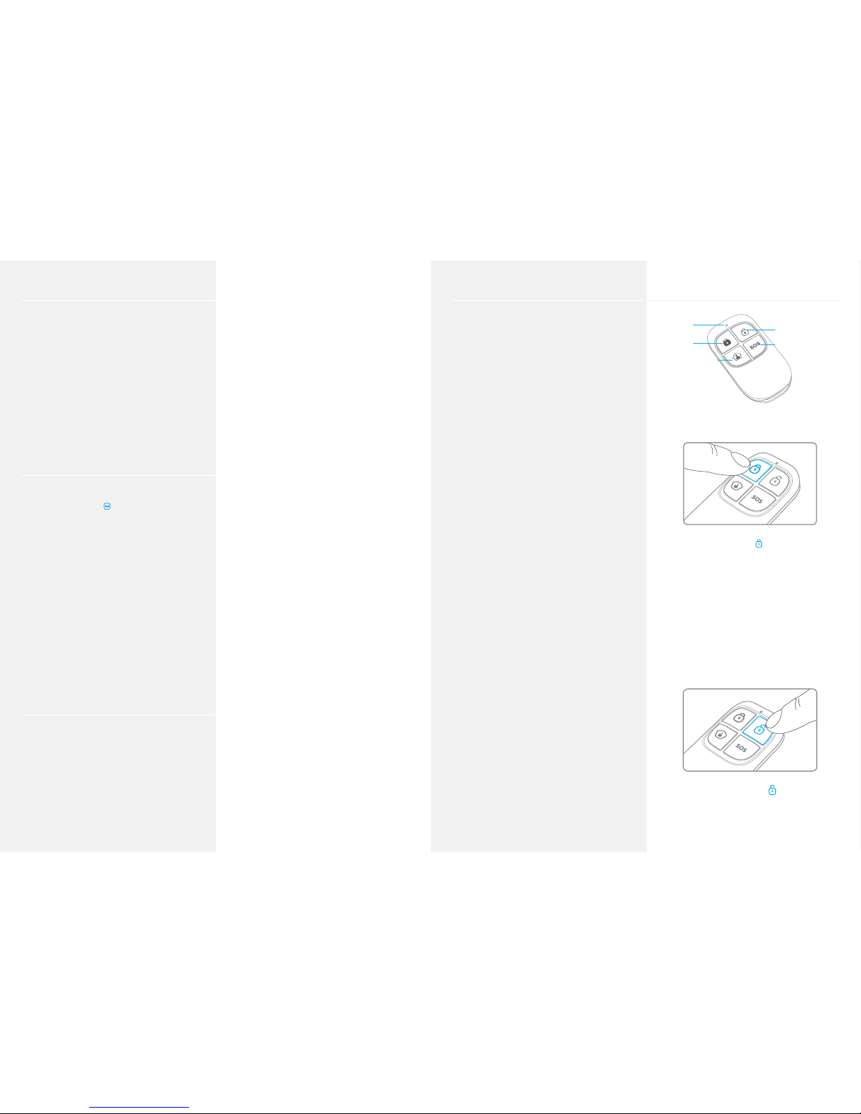
Wireless Remote Control
LED indicator
Arm
Home mode
Disarm
Panic
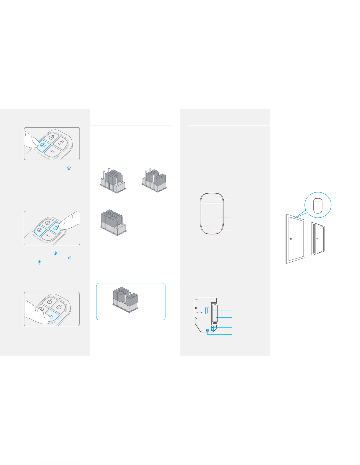
Arm the system
Press the Arm button { } to arm the alarm
system. The LED indicator lights up (the siren
rings out once). The system is armed.
If an intruder is detected, the siren rings
out. (The siren turns o after 5 minutes as
per default setting.) In the meantime, the
system dials the pre-stored phone numbers
automatically.
Disarm the system
Press the Disarm button { } to disarm the
alarm system. The LED indicator turns o (the
siren rings out twice). The system is disarmed.
Page 9
16 17
Home Mode
Press the Home Mode button { } on the
remote control. The system state LED is on. All
the sensors in regular zones are armed except
those in the Home Mode zone. The sensors in
the Home Mode zone are disarmed so that
users can move inside their home.
Mute Mode
Press the Stay button { } on the remote
control. Press the Arm button { } or the
Disarm button {
}. When arming or disarming
the system, the siren does not ring out: the
system is armed or disarmed in Mute Mode.
Emergency Mode
Regardless the status of the system, the alarm
is triggered when the Panic button {SOS} is
pressed on the remote control.
Zone Setup of Wireless Accessories
Every detector can be assigned to 4
dierent categories of zones: Home Mode
Zone, Single Delay Zone, Normal Zone
and 24-H Zone. To assign a detector to a
zone, open its case and move its jumpers
according to the drawing below:
D0
D3
D0
D3
A. Home Mode Zone B. Single Delay Zone
D0
D3
C. Normal Zone
The PIR motion detector is set in Home
Mode Zone by default. It is recommended
to set the Door / Window Contact at the
entrance of your home in Single Delay Zone.
After a zone has been changed, the detector
must be registered in the control panel again.
24-H Zone
D3
D0
Note
It is recommended to set the smoke
detector, the gas detector and the outdoor
beam sensor at 24-H zone.
Wireless Door / Window Contact
Features
The ES-D3A is a Door / Window Contact that
can be installed on doors, windows, and
any other objects that open and close. The
sensor sends signals to the control panel
when the magnet installed next to the
sensor is deconnected.
Thanks to the tamper switch, any attenpt
to move the Door / Window Contact will
trigger the alarm.
Magnet
Transmier
LED indicator
LED indications
Blinks once: the door or window is open
and the transmitter sends a signal to the
control panel.
Blinks quickly: Low power indication: the
batteries must be replaced.
PCB Layout
LED working indicator
Zone seng
A23 12V Baery
Tamper switch
Installation
- Open the case and remove the battery
activation strip.
- Mount the sensor on the door and the magnet
on the door frame.
- Make sure the magnet is placed above of the
transmitter.
- Mount the magnet max. 1cm away from the
transmitter and secure the transmitter and
magnet with double-sided tape or screws.
- Avoid mounting the sensor in areas with a
large amount of metal or electrical wiring, such
as a furnace or utility room.
Specications
Power supply
DC 12V (A23 12V Battery x 1)
Static current
≤ 30 uA
Alarm current
≤ 40 mA
Transmitting distance
≤80 m (in open area)
Radio frequency
315 MHz / 433 MHz (±75 KHz)
Page 10
18 19
Housing material
ABS plastic
Operating temperature
-10°C~55°C
Relative humidity
≤80% (non-condensing)
Transmitter dimensions (LxWxH)
71 x 34 x 17.5 mm
Magnet dimensions (LxWxH)
51 x 12 x 13.5 mm
Wireless PIR Motion Detector
Features
ES-D1A (or ES-D2A: Pet-Immune Motion
Detector) is a high performance wireless
P.I.R. motion detector. It boasts a digital
dual-core fuzzy logic infrared control chip
with intelligent analysis. This technology
identies interferences created by body
motion and reduces the false alarm rate.
With automatic temperature compensation
and anti-air turbulence technology, it easily
adapts to environmental changes.
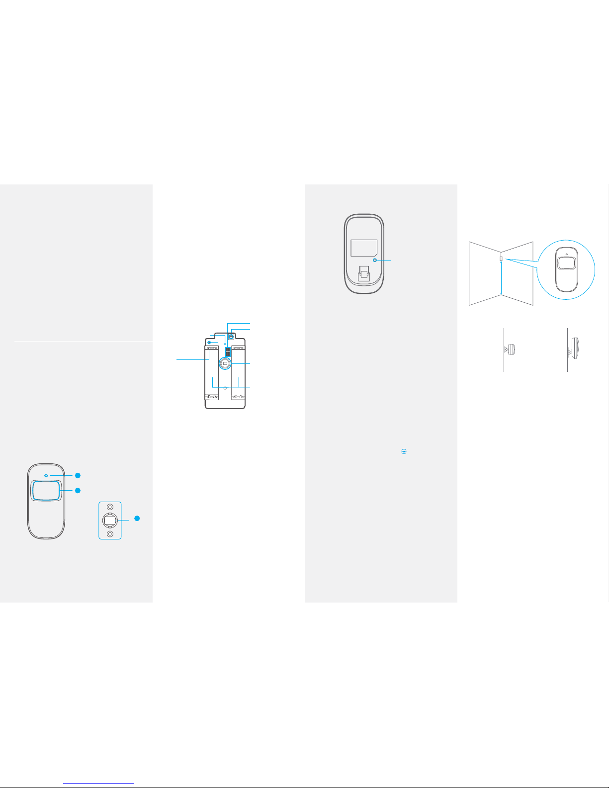
3
1
2
1. LED indicator
2. Detection window
3. Bracket
LED indications
Blinks continuously: self-testing
Blinks once: an intruder is detected
Blinks twice: self-testing is complete; entering
working mode.
Blinks once every 3 seconds: under-voltage
indication: the batteries must be replaced.
(The user will be informed by SMS when the
batteries are low if the PIR Motion Detector is
registered in the control panel.)
PCB Layout
Alarm zone setup
Tamper switch
Infrared sensor
AA 1.5V LR6
Antenna
LED working indicator
Infrared sensor
Detects the infrared rays released by human
body motion. Do not touch the surface. Keep
the surface clean.
Tamper switch
When the alarm system is armed, the tamper
switch will trigger the alarm if the case is
opened.
Usage
Open the case and remove the battery
activation strip to activate the batteries. Selftesting will start for one minute.
Mode Setting
Test Buon
Testing mode
Once the self-testing is complete, press the
test button. The sensor switches to testing
mode, and scans once every 10 seconds.
After 3 minutes, the LED blinks twice, and
the sensor switches to working mode.
Working mode
In working mode, if the sensor is triggered
more than twice within 3 minutes, it will
switch to standby mode to save power. If
a movement is detected within the next
3 minutes, the standby mode is extended
by 3 more minutes. If no movement has
detected within these 3 minutes, the
detectors turns back to working mode.
Register in the control panel
Press the Connect button { } on the control
panel. Press the test button of the sensor
twice. The control panel beeps once: the
motion detector is registered.
To check if the registration is complete, arm
the system and trigger the sensor again.
If the siren rings out, the registration is
successful.
Installation
Avoid mounting the detector close
to windows, air conditioner, heater,
refrigerator, oven, sunshine and places
where the temperature changes fast or
where the air stream ows frequently.
If two detectors are installed in the same
detection scope, adjust the location to avoid
interferences and false alarms.
Top
Boom
Ground
2.2 m
Side view
Top view
Fix the bracket on the wall with screws and
attach the detector to the bracket. Adjust
the bracket to change the detection distance
and angle. It is recommended to mount the
detector 2m from the ground.
The detector is more sensitive to cross
movements than vertical movements.
Testing
A. After one minute of self-testing, press the
test button, walk in the scope of detection
and watch the LED indicator to make sure the
detector is working.
B. The LED indicator blinks once when body
movement is detected.
C. Adjust the detector angle to achieve the best
detection performance.
Page 11
20 21
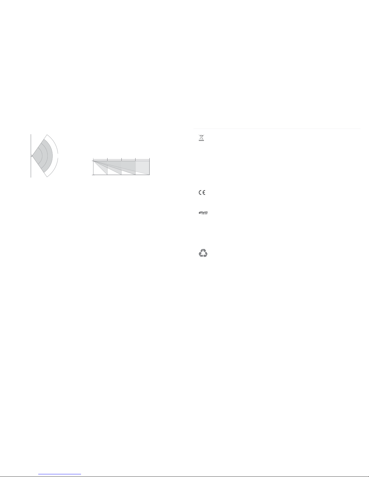
Detection Scope
110°
Top view
0m 2m 4m 6m 8m
2m
0m
Side view
Specications
Power supply
DC 3V (AA 1.5V LR6 Batteries x 2)
Static current
≤ 50uA
Alarm current
≤ 9.5 mA
Detection scope
8m / 110°
Trating distance
≤ 80m (in open area)
Radio frequency
315 MHz / 433 MHz (±75 KHz)
Housing material
ABS plastic
Operating Condition
Temparature: -10°C~55°C
Relative humidity: ≤ 80% (non-condensing)
Detector dimensions (L x W x H)
108 x 52 x 36.8 mm
Bracket dimensions (L x W x H)
52 x 30 x 26.5 mm
Standards
This product bears the selective sorting symbol for waste electrical and electronic equipment
(WEEE). This means that this product must be handled pursuant to European Directive
2002/96/EC in order to be recycled or dismantled to minimize its impact on the environment.
For further information, please contact your local or regional authorities.
Electronic products not included in the selective sorting process are potentially dangerous for the
environment and human health due to the presence of hazardous substances.
In compliance with European laws.
This product was designed and manufactured in compliance with Directive 2002/95/EC of the
European Parliament and of the Council on the restriction of use of certain hazardous substances
in electrical and electronic equipment (RoHS Directive - RoHS) and is deemed to comply with
the maximum concentration values set by the European Technical Adaptation Committee (TAC).
Manufactured in China.
Images, illustrations and text are non-contractual. ETIGER and the ETIGER logo are registered
trademarks and the property of ETIGER. Copyright © 2014 ETIGER. All rights reserved.
ETIGER EUROPE
Rue de la Loi, 25, 7100 La Louvière, Belgium
S3-S – UM-20140328:1.2
Page 12

www.etiger.com
 Loading...