

ETIC XSLAN-1100 User Manual
DOC_DEV_XSLAN-1100_User guide_A
XSLAN-1100
Switch SHDSL
_________________
USER GUIDE
_________________

DOC_DEV_XSLAN-1100_User guide_A Page 2
The product XSLAN-1100 is designed and manufactured by
ETIC TELECOM
13 Chemin du vieux chêne
38240 MEYLAN
FRANCE
TEL : + (33) (0)4-76-04-20-05
E-mail : hotline@etictelecom.com
web : www.etictelecom.com

DOC_DEV_XSLAN-1100_User guide_A Page 3
DECLARATION OF CONFORMITY
The manufacturer, ETIC Telecom – 13 chemin du vieux chêne – 38240 Meylan – France, Hereby declares
under sole responsibility that the listed devices conform to
- the Electromagnetic Compatibility (EMC) Directive 2014/30/UE,
- the Low Voltage Directive (LVD) 2014/35/UE,
- the Restriction of the use of certain Hazardous Substances (RoHS 2) Directive 2011/65/UE.
Type of device: SHDSL switch
Models: XSLAN-1100
The harmonized standards to which these devices comply are:
Standard
Title
EN 61000-6-2 2006
Immunity:
EN61000-4-2 Electrostatic Discharge
EN61000-4-3 RF Radiated Immunity
EN61000-4-4 EFT/Burst Immunity
EN61000-4-5 Surge Immunity
EN61000-4-6 RF Conducted Immunity
EN61000-4-8 Power Frequency Magnetic Field Immunity
EN 61000-6-4 2007
A1/2011
Emission:
EN55022 Radiated and conducted emission
IEC/EN 62368
Safety and Health
Date : 06th March 2019
Philippe Duchesne
Technical Director


TABLE OF CONTENTS
DOC_DEV_XSLAN-1100_User guide_A Page 5
OVERVIEW ..................................................................................................................................... 7
1 Purpose of this manual .................................................................................................................................... 7
2 Specifications.................................................................................................................................................... 7
3 EMC & Environment compliances .................................................................................................................... 9
4 Product overview ............................................................................................................................................ 11
INSTALLATION ........................................................................................................................... 13
1 Description ...................................................................................................................................................... 13
1.1 Dimensions .......................................................................................................................................... 13
1.2 Connectors ........................................................................................................................................... 13
1.3 Push-buttons ........................................................................................................................................ 15
1.4 LED indicators ...................................................................................................................................... 16
2 Safety instructions .......................................................................................................................................... 16
3 DIN rail mounting ............................................................................................................................................ 17
4 cooling ............................................................................................................................................................. 17
5 Alimentation .................................................................................................................................................... 17
6 Earthing ........................................................................................................................................................... 17
7 Preparing and checking the line ..................................................................................................................... 18
7.1 Type of cable ....................................................................................................................................... 18
7.2 Crosstalk interference ......................................................................................................................... 18
7.3 Shield earthing ..................................................................................................................................... 18
7.4 Protecting the SHDSL switch from lightning ..................................................................................... 19
8 Connecting the XSLAN to the line .................................................................................................................. 19
COMMISSIONING ....................................................................................................................... 21
PREPARING THE ADVANCED SETUP ....................................................................................... 23
1 Connecting a PC for configuration ................................................................................................................ 23
1.1 Overview ............................................................................................................................................... 23
1.2 First configuration ............................................................................................................................... 24
1.3 Changing the configuration later ........................................................................................................ 24
2 Temporary return to the factory settings ...................................................................................................... 25
3 Restoring the factory settings ........................................................................................................................ 25
4 Protecting the access to the administration server ...................................................................................... 26
5 Configuration steps ........................................................................................................................................ 26
ANNEX 1 : SHDSL data rate versus distance ........................................................................... 27

OVERVIEW
DOC_DEV_XSLAN-1100_User guide_A Page 7
OVERVIEW
1 Purpose of this manual
The present user guide describes the features and the installation of the SHDSL switch XSLAN-1100.
In the rest of the document the term "XSLAN" is also used to designate the product.
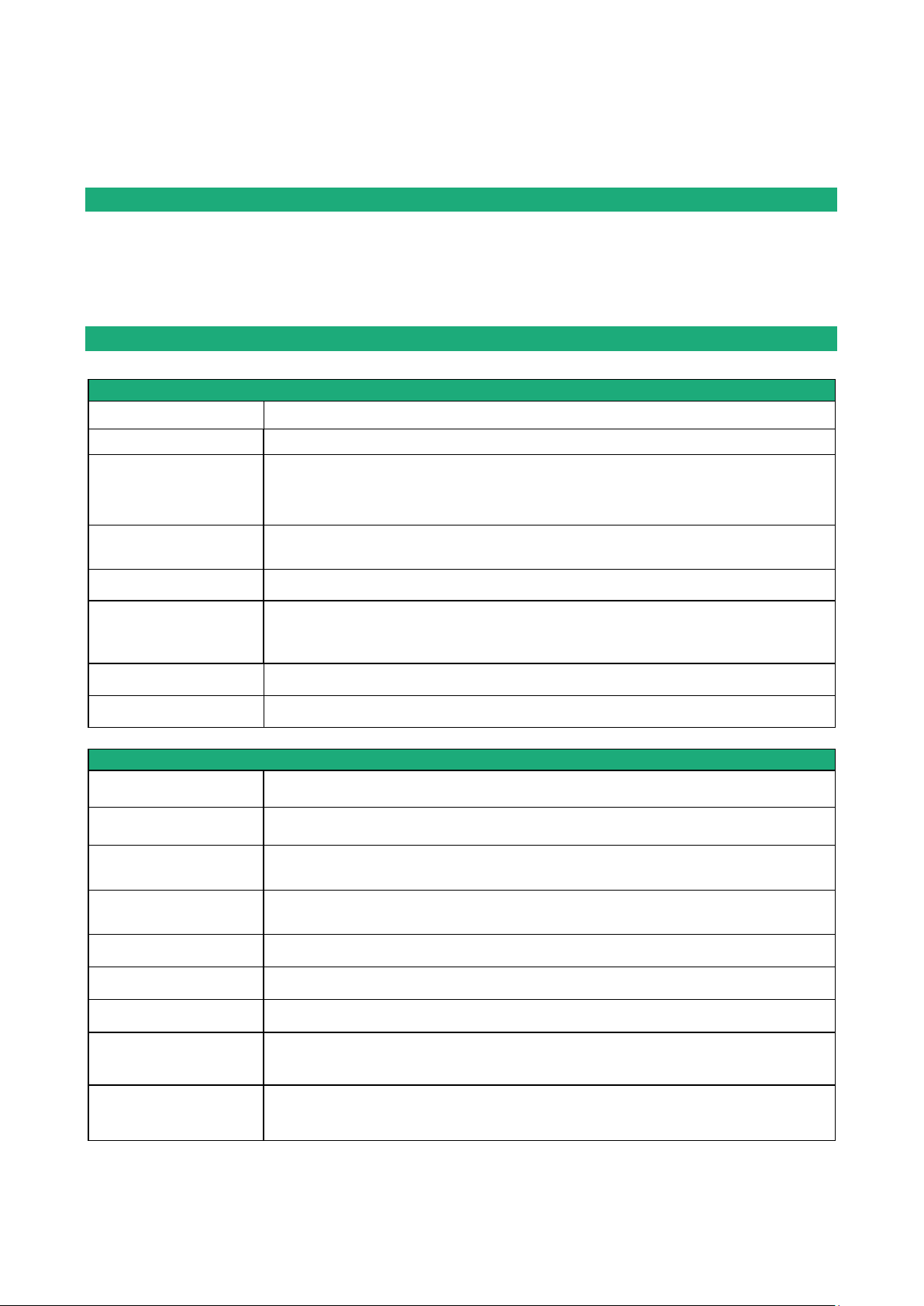
2 Specifications
General characteristics
Dimensions
120 x 37 x 88 mm (h,l,p)
Weight
0.44 kg
Casing
Metallic
IP41 – IEC60529
DIN rail mounting
Temperature
Non-operating: -40°/ +85°C
Operating: -20°/ +70°C
Humidity
5 à 95 % relative (non-condensing)
Power supply
Protected against reverse polarity
Nominal : 12-24 VDC (min 10 VDC - max 30 VDC)
2 points Phoenix connector
Consumption
1.8 W
MTBF
730 000 h at 22 °C - MIL-HDBK-217F-N2 GB
SHDSL
Modulation
ITU-T G.991.2, 802.3ah : 2BaseTL (EFM)
Data rate
192 kb/s to 15,2 Mb/s
Emission power
Annex A : 13.5 dBm (22 mW)
Annex B : 14.5 dBm (28 mW)
Voltage of the emitted
signal
6 to 8 V peak to peak on 135 Ohms
Signal spectrum
< 3 MHz at 15 Mb/s
Isolation
1500 V
Connection time
45 s typical
Plug & play
STU-C / STU-R auto-negotiation
Automatic adaptation of the data rate
Latency
Frame transmission delay from one Ethernet port of an XSLAN+ to the Ethernet port of
another XSLAN+ through an SHDSL link : 2 ms at 5.6 Mb/s

PRESENTATION
DOC_DEV_XSLAN-1100_User guide_A Page 8
ETHERNET & IP
Ethernet
10/100 Mb/s Half/Full duplex Auto MDI/MDIX
Switch
Store and forward - 1024 MAC addresses
Redondancy
RSTP - IEEE 802.1D / 802.1Q
VLAN
IEEE 802.1Q
IP address
IPV4 and IPV6
IP router
Multicast and broadcast filtering
Static routes
RIP V2 - OSPF
QOS
RFC 2474, 2475, 2597, 2598 « Differentiated services »
Traffic prioritization and bandwidth reservation
Misc.
SNMP
Supported MIBs:
RFC1213-MIB (MIB-2)
HDSL2-SHDSL-LINE-MIB
HOST-RESOURCES-MIB / IF-MIB
IP-MIB
BRIDGE-MIB
RSTP-MIB
SNMP traps
Date and time
NTP client and server
Configuration
Web serveur
Log
Log with timestamp of the last 300 events
Syslog
Management
Save and restore configurations
Reset product to return to factory configuration
OVERVIEW
DOC_DEV_XSLAN-1100_User guide_A Page 9
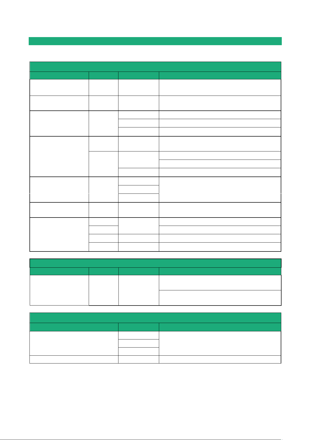
3 EMC & Environment compliances
EMC Immunity, EN61000-6-2
Standard
Criteria
Port
Level pass
EN61000-4-2
ESD
B
Enclosure
+/-4kv contact
+/-8kv air discharge
EN61000-4-3
Radiated
A
Enclosure
10V/M AM @ 1khz 80Mhz to 3Ghz
EN61000-4-4
Burst
B
SHDSL
+/- 2kv
Power supply
+/- 2kv
Ethernet
+/- 2kv
EN61000-4-5
Surge
B
SHDSL
+/- 5kv common mode (Normal and Telecom
surge)
B
Power supply
+/- 0,5kV common mode
+/- 0,5kV differential mode
Ethernet
+/- 4kv direct shield coupling
EN61000-4-6
RF conducted
A
SHDSL
10VAM 80% 1khz, 150khz to 80Mhz
Power supply
Ethernet
EN61000-4-8
Magnetic
A
Enclosure
30 A/M at 50hz/60hz
EN61000-4-18
Damped wave
A
Power supply
+/- 0,5kV differential
B
+/- 1kV common mode
A
Ethernet
+/- 1kV common mode
B
SHDSL
+/- 1kV common mode
EMC Immunity, ITU -T-K21
Test
Criteria
Port
K44 Test N°
Lightning voltage,
special test protector
A
SHDSL
2.1.2a
+/- 5kV transverse mode (Basic level)
2.1.2b
+/- 5kV port to earth (Basic level)
EMC Emissions, EN61000-6-4
Emission test
Criteria
Limits
conducted Disturbance
Power supply
EN55032, Class A: 150khz to 30Mhz
SHDSL
Ethernet
Radiated emission
Enclosure
EN55032, Class A: 30Mhz to 1Ghz
 Loading...