

Page 1

SIG
TLS or IPSec VPN server
_________________
User manual
Document reference : 9017409-01
_________________
Page 2

The SIG router & VPN server is manufactured by
ETIC TELECOM
13 Chemin du vieux chêne
38240 MEYLAN
FRANCE
TEL : + (33) (0)4-76-04-20-05
FAX : + (33) (0)4-76-04-20-01
E-mail : [email protected]
web : www.etictelecom.com
Page 3

CONTENT
SIG Router & VPN server User’s guide ref. 9017409-01 Page 3
PRESENTATION
1 TECHNICAL DATA......................................................................................................7
2 OVERVIEW..................................................................................................................9
INSTALLATION
1
PRODUCT DESCRIPTION........................................................................................10
2 INSTALLATION.........................................................................................................11
CONFIGURATION
1 CONFIGURING THE SIG ROUTER ..........................................................................13
1.1 Overview .......................................................................................................13
1.2 First configuration .......................................................................................14
1.3 Modifying the configuration........................................................................15
2 REBOOTING THE ROUTER AFTER PARAMETERS CHANGES...........................16
3 RECOVERING THE IP ADDRESS OF THE ROUTER..............................................16
4 RECOVERING THE FACTORY CONFIGURATION.................................................16
5 RESTRICTING ACCESS TO THE ADMINISTRATION SERVER.............................17
6 ASSIGNING IP ADDRESSES TO THE LAN AND THE WAN INTERFACES ..........18
6.1 Principles of operations..............................................................................18
6.2 LAN interface parameters ...........................................................................19
6.3 WAN interface parameters .........................................................................21
7 CREATING VPN CONNECTIONS BETWEEN ROUTERS......................................22
7.1 Principles......................................................................................................22
7.2 IPSec VPN connections...............................................................................24
7.3 TLS VPN connections..................................................................................30
../..
Page 4

CONTENT
Page 4 User’s guide ref 9017409-01 SIG Router & VPN server
… CONFIGURATION
8 ROUTING FUNCTIONS.............................................................................................35
8.1 Basic routing function.................................................................................35
8.2 Static routes .................................................................................................36
8.3 RIP protocol..................................................................................................37
9 ADDRESS AND PORT TRANSLATION ...................................................................38
9.1 Port forwarding ............................................................................................38
9.2 Advanced network address and port translation......................................39
10 VRRP REDUNDANCY...............................................................................................44
10.1 Principle........................................................................................................44
10.2 Configuring VRRP on the LAN interface....................................................45
10.3 Configuring VRRP on the WAN interface .................................................46
11 REMOTE USERS CONNECTIONS SERVICE ..........................................................47
12 REMOTE USERS CONNECTIONS...........................................................................48
12.1 Principles......................................................................................................48
12.2 Configuring a TLS connection....................................................................49
12.3 Configuring a PPTP connection.................................................................52
13 USERS LIST...............................................................................................................53
14 FIREWALL.................................................................................................................56
14.1 Overview .......................................................................................................56
14.2 Main filter ......................................................................................................58
14.3 Remote users filters.....................................................................................62
../..
Page 5

CONTENT
SIG Router & VPN server User’s guide ref. 9017409-01 Page 5
… CONFIGURATION
15
ADVANCED FUNCTIONS.........................................................................................67
15.1 Adding a certificate......................................................................................67
15.2 Alarms......................................................................Erreur ! Signet non défini.
15.3 Configuring the web portal .........................................................................68
15.4 Configuring the DNS server........................................................................69
1 DIAGNOSTIC.............................................................................................................71
2 SAVING THE PARAMETERS TO A FILE.................................................................72
3 UPDATING THE FIRMWARE....................................................................................72
1 OVERVIEW................................................................................................................77
2 FUNCTIONS...............................................................................................................78
3 OPERATION..............................................................................................................78
Appendix 1 : Administration html server
Appendix 2 : VPN mechanisms
Page 6

Page 7
INSTALLATION
SIG Router & VPN server User’s guide ref. 9017409-01
Page 7
1 Technical data
General characteristics
Dimensions 137 x 48 x 116 mm (h, l, p)
Electrical safety EN 60950- UL 1950
EMC
ESD : EN61000-4-2 : Discharge 6 KV
RF field : EN61000-4-3 : 10V/m < 2 GHz
Fast transient : EN61000-4-4
Surge voltage : EN61000-4-5 : 4KV line / earth
RoHS 2002/95/CE (RoHS)
Supply voltage 110 to 230 VAC - 50/60Hz - 60 W
Operating T° +5°C / + 40°C Humidity 5 - 95 %
Internet connection ( Ethernet 4)
Type
Bridge : PPPo Ethernet
IP Router
Ethernet / IP router
Ethernet
10/100 BT
Port Ethernet 1 : LAN conection
Port Ethernet 4 : WAN connection
IP router Remote connections- static routes - RIP V2
Ip address
translation
Source IP @ translation (NAT)
Destination IP @ translation (DNAT)
Port translation (Port forwarding)
DNS
IP address assignment LAN interface : Fixed IP @ or DHCP server
Throughput 30 MB/s
Page 8
INSTALLATION
Page 8 User’s guide ref 9017409-01 SIG Router & VPN server
VPN and firewall
VPN
• 128 VPN
• IPSec - Client or server - PSK or X509
certificates
• TLS/SSL - Client or server - X509 certificates
• Encryption 3DES
Firewall Stateful packet inspection
Logs Event logs (date and time)
Remote access server (RAS)
User list 25 users
Connection
VPN PPTP / L2TP-IPSec / TLS Open VPN
Login & password
Certificate X509
Alarms 3 inputs : emails
Page 9
INSTALLATION
2 Overview
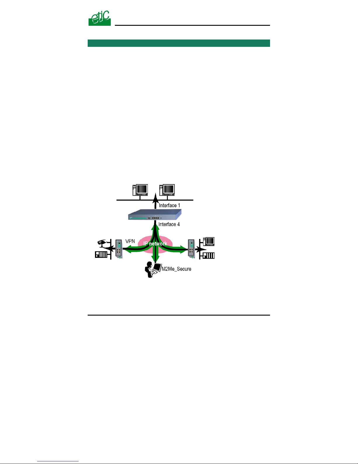
The SIG is designed to build safe and reliable remote control system
through the internet or private extended networks.
The SIG comes with two 10/100 BT Ethernet interfaces :
The WAN interface (Interface Ethernet 4)
On that interface, the SIG behaves as a VPN server.
The LAN interface (Ethernet 1).
The SIG is at the same time
a VPN server able to manage up to 128 IPSec or TLS tunnels,
an IP router to route IP packets between its two interfaces.
a remote access server (RAS) to give a secure access to the LAN
or to the remote sites for authenticated remote users.
.
SIG Router & VPN server User’s guide ref. 9017409-01 Page 9
Page 10
INSTALLATION
1 Product description
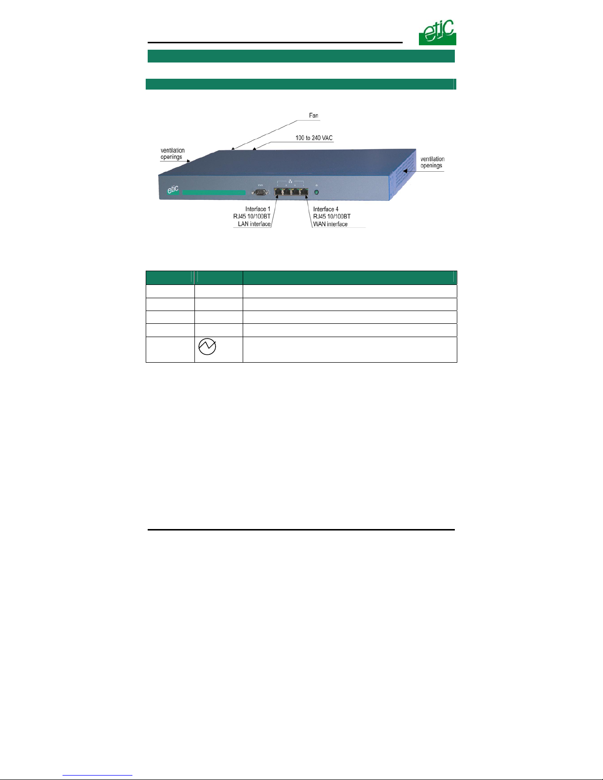
SIG router
Interface Led Function
Ethernet 1
DATA
Blinking quickly : Data activity
LINK
Lit : Interface connected
Ethernet 4
DATA
Blinking quickly : Data activity
LINK
Lit : Interface connected
Power led
Page 10 User’s guide ref 9017409-01 SIG Router & VPN server
Page 11

INSTALLATION
SIG Router & VPN server User’s guide ref. 9017409-01 Page 11
Ethernet RJ45 connector
Ethernet 10/100 BT
Pin Nr Signal Function
1 Tx + TX polarity +
2 Tx - TX polarity 3 Rx + Reception polarity +
4 N.C 5 N.C 6 Rx - Reception polarity 7 N.C. 8 N.C. -
2 Installation
The product includes a fan.
Mount the SIG router in a 19 inch rack or place it on a flat surface.
Leave 10 cm of clearance at the sides and in the rear to avoid
overheating.
Attach the brackets.
Secure the SIG router to the rack with the rack-mounting screws.
.
Page 12

Page 13

CONFIGURATION
SIG Router & VPN server User’s guide ref. 9017409-01
Page 13
1 Configuring the SIG router
1.1 Overview
Administration server address
The administration html server is located at the LAN IP address of the router (The default
address is192.168.0.128).
Html browser
We advise to use Internet Explorer version 8.
First set up
For the first configuration, we advise to connect the PC directly to the LAN interface
(Ethernet 1) of the SIG router.
Set up modifications
Modifications can be carried out from the LAN, or remotely from the WAN through a VPN
or setting a remote access connection (RAS connection).
Network IP address
Later in the text, we often speak of “network address”.
We mean the lowest value of the addresses of the network.
For instance, if the netmask of a network is 255.255.255.0, the network address of that
network is X.Y.Z.0.
Copy and paste
Parameters must be entered with the keyboard; they cannot be pasted.
However, it can be useful to paste a string when it is long and to avoid errors.
In that case, paste the string, delete the last character of the pasted string, and enter it
again with the keyboard.
Saving and restoring the parameters file (see the maintenance
chapter)
A parameters file can only be downloaded to a product having the same firmware version.
It is why, we advise to assign a name to a parameters file including the product name and
the software version like for instance “myrouterfile_iplE1220_V241.bin”.
Page 14
CONFIGURATION
1.2 First configuration
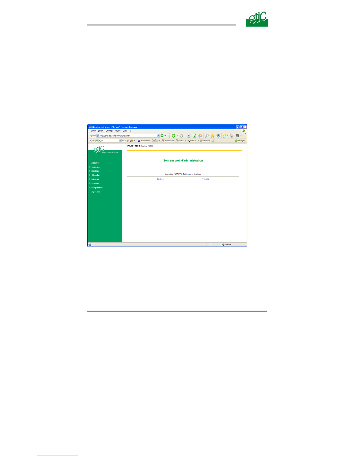
Step 1 : Create or modify the PC’s IP connection.
Assign to the PC an IP @ in accordance with the SIG IP address.
For the first configuration, assign or instance 192.168.0.127 to the PC.
Step 2 : Connect the PC directly to the LAN interface (Ethernet 1) of
the SIG using any Ethernet cable (straight or cross wired).
Step 3 : Launch the navigator
Enter the LAN IP @ of the router 192.168.0.128.
The Home page of the administration server is displayed
Page 14 User’s guide ref 9017409-01 SIG Router & VPN server
Page 15

CONFIGURATION
SIG Router & VPN server User’s guide ref. 9017409-01 Page 15
1.3 Modifying the configuration
Modifications from the LAN (Interface 1)
Modifications can be carried out from the LAN at the IP address assigned
to the html server.
• Launch the html browser and enter the IP address assigned to the
router.
• Or, launch the ETICFINDER utility to detect the SIG address.
• Enter the login and password which may restricts the access to the
html server.
Modifying the configuration from the WAN
The html administration server can be reached from the WAN either
through a PPTP or TLS or L2TP/ IPSec remote user connection or
through a VPN tunnel.
Page 16

CONFIGURATION
Page 16 User’s guide ref 9017409-01 SIG Router & VPN server
2 Rebooting the router after parameters changes
• After the parameters of any page have been entered, click the
« Save » button at the bottom of the page.
• After some parameters changes, the SIG must restart.
When the configuration has been completely carried out, click the
« Reboot » red button in the green bar, when displayed.
• Once the product has restarted, check the « Reboot » button has
disappeared from the green bar.
To save the configuration file to a hard disk :
• Select the “maintenance” menu and then the “Save / restore” menu.
• Click the “Save current configuration to disk” button.
3 Recovering the IP address of the router
If you cannot access the SIG by any method, it is possible to recover the
stored IP address by using the ETIC FINDER software provided by ETIC
TELECOM.
4 Recovering the factory configuration
It may be necessary to restore the factory configuration of the router.
To restore the SIG factory configuration,
• Switch OFF the SIG router.
• Connect a key board to the USB port of the SIG router.
• Switch on the SIG router.
• Press ALT + CONTROL SUP at last 30 seconds after switching the
router on.
Remark : The stored configuration will be lost; the factory IP address
192.168.0.128 will be restored.
Page 17
CONFIGURATION
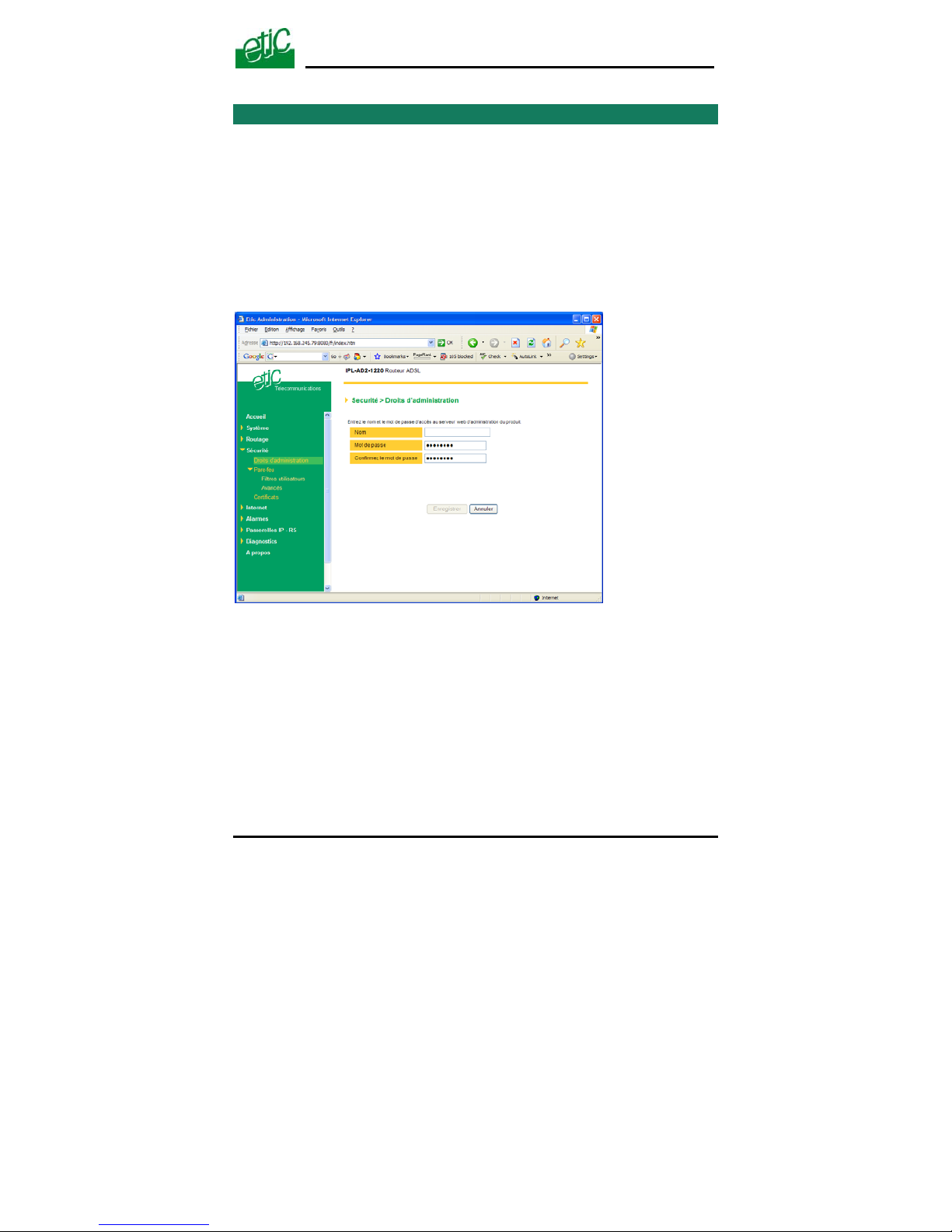
5 Restricting access to the administration server
The access to the administration server can be protected by a login and
password.
To protect access to the administration server,
• Select the “Set up” menu, the “Security” menu and then the
“Administration menu”.
Remark : For more simplicity, we advise to chose the login and the
password of one of the remote users stored in the user list.
SIG Router & VPN server User’s guide ref. 9017409-01
Page 17
Page 18

CONFIGURATION
Page 18 User’s guide ref 9017409-01 SIG Router & VPN server
6 Assigning IP addresses to the LAN and the WAN interfaces
6.1 Principles of operations
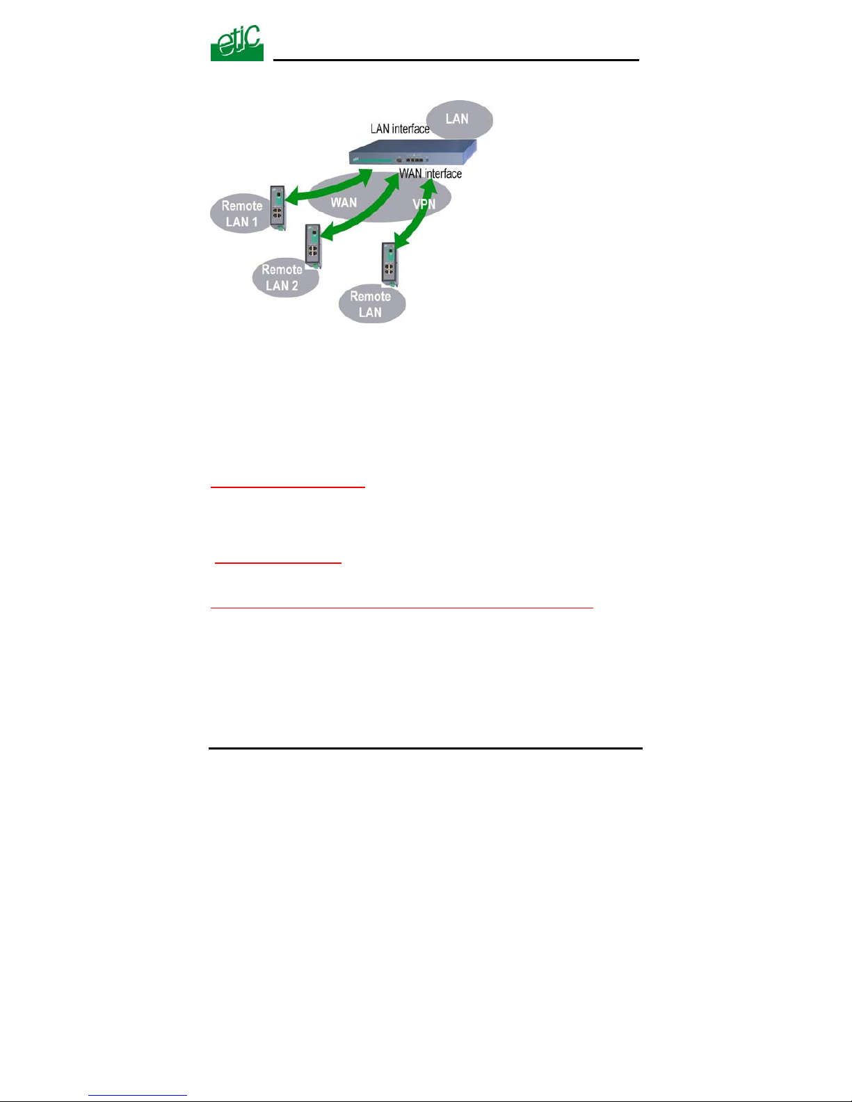
The SIG features two Ethernet interfaces :
• The LAN interface (Ethernet port 1) :
On that interface, the following IP addresses must be entered :
The router IP address on the LAN interface *.
The IP addresses pool assigned to the remote users when they
connect.
* The administration html server is located at that address.
• The WAN interface :
The WAN interface is the « Ethernet Nr 4 » interface.
The SIG behaves at the same time like a VPN server and like a remote
access server on that interface.
• IP addresses assignment rules :
The SIG router will be able to route packets between the LAN and the
WAN interface only if the IP address assigned to the network connected
to the LAN interface is different from the one assigned to the WAN
interface.
Page 19
CONFIGURATION
Moreover The LAN IP address must be different from any of the remote LAN IP address.
6.2 LAN interface parameters
6.2.1 IP addresses
• Click the « Configuration» menu and then « LAN interface» and
then “IP protocol”.
“IP address” parameter :
Enter the IP address assigned to the router over the LAN interface.
That IP address will have to be entered to display the administration
server of the router.
”Netmask” parameter
:
Enter the IP netmask assigned to the LAN
“Start of users IP address pool” & “end of users IP addresses pool” parameters :
That parameters define the pool of addresses which will be assigned
automatically to remote user’s PC when they will connect to the router.
Enter the start address and the end address.
SIG Router & VPN server User’s guide ref. 9017409-01
Page 19
Page 20

CONFIGURATION
Page 20 User’s guide ref 9017409-01 SIG Router & VPN server
6.2.2 DHCP server configuration
Over the LAN interface, the SIG router can behave like a DHCP server.
If you select that option, we advise to assign a fixed IP address to the SIG
router itself over the LAN interface.
To configure the DHCP server function,
• select the « Set up» menu and then « LAN interface» and
then « DHCP server ».
•
“IP address pool start” & “IP addresses pool end” parameters :
That parameters define the range of IP addresses which can be assigned by the
SIG to the DHCP client devices.
•
“Primary DNS IP address” & “secondary DNS IP address” parameters :
Enter the IP addresses of the domain name servers.; the DHCP server
will communicate that addresses to the DHCP client devices.
Page 21

CONFIGURATION
SIG Router & VPN server User’s guide ref. 9017409-01 Page 21
6.3 WAN interface parameters
The « Ethernet 4 » RJ45 connector is the WAN interface.
The SIG can be connected to a company network or to any Internet router
through that interface.
• Select the « Internet» menu and then « WAN interface» and then
“Connection”.
“Obtain an IP address automatically” parameter
:
Set that option if a DHCP server is in charge of attributing an the IP
address of the WAN interface of the router.
Otherwise, enter WAN interface IP address, netmask and default gateway
IP address parameters.
“IP address” & “netmask” parameters
:
Enter the IP address and netmask assigned to the WAN interface of the
router.
“Default gateway” parameter
:
Enter the IP address of the default gateway.
”Obtain DNS IP addresses automatically” parameter
: Select that
option if the Domain name server IP addresses are provided automatically
through the WAN interface.
Otherwise, enter the DNS servers IP addresses.
“Primary DNS IP address
” & “secondary DNS IP address” parameters :
Enter the IP addresses of the domain name servers.
“Activate network address translation” parameter :
If that option is selected, the source IP address of any packet coming
from a device connected to the LAN interface and routed to the WAN
interface, is replaced by the SIG router WAN IP address.
Page 22

CONFIGURATION
7 Creating VPN connections between routers
7.1 Principles
A VPN tunnel is a safe link set between two end-points routers over an IP
network : Both routers authenticate, data are encrypted and each device
of a LAN can exchange data with each device of the other one.
To get more explanations about how VPNs work, refer to appendix 1.
128 VPNs can be set on the WAN interface of the SIG router.
Two types of VPN can be set : TLS VPNs and IPSec VPNs.
IPSec has the advantage to be a standard solution.
TLS is easier to employ because the transport layer is TCP or UDP; it is
why, it can be easily used when the VPN must pass through several or
even numerous company routers.
Once a type of VPN (TLS or IPSec) has been selected, all the VPN set
with the SIG router will be of the same type.
Two steps are necessary to configure the SIG to create VPN connections
between routers :
1
st
step : Select the VPN type and set up the VPN parameters
Once a type of VPN has be selected, it applies to all the connections with remote routers.
2
nd
step : Create VPN connections
A connection can be an
incoming connection or
an outgoing connection.
If a connection is an
incoming connection, the
local router is named
“VPN server” and the
remote router is a “VPN
client”.
VPN
Outgoing
connection
Ingoing
connection
VPN
client
VPN
server
IP network
Page 22 User’s guide ref 9017409-01 SIG Router & VPN server
Page 23
CONFIGURATION
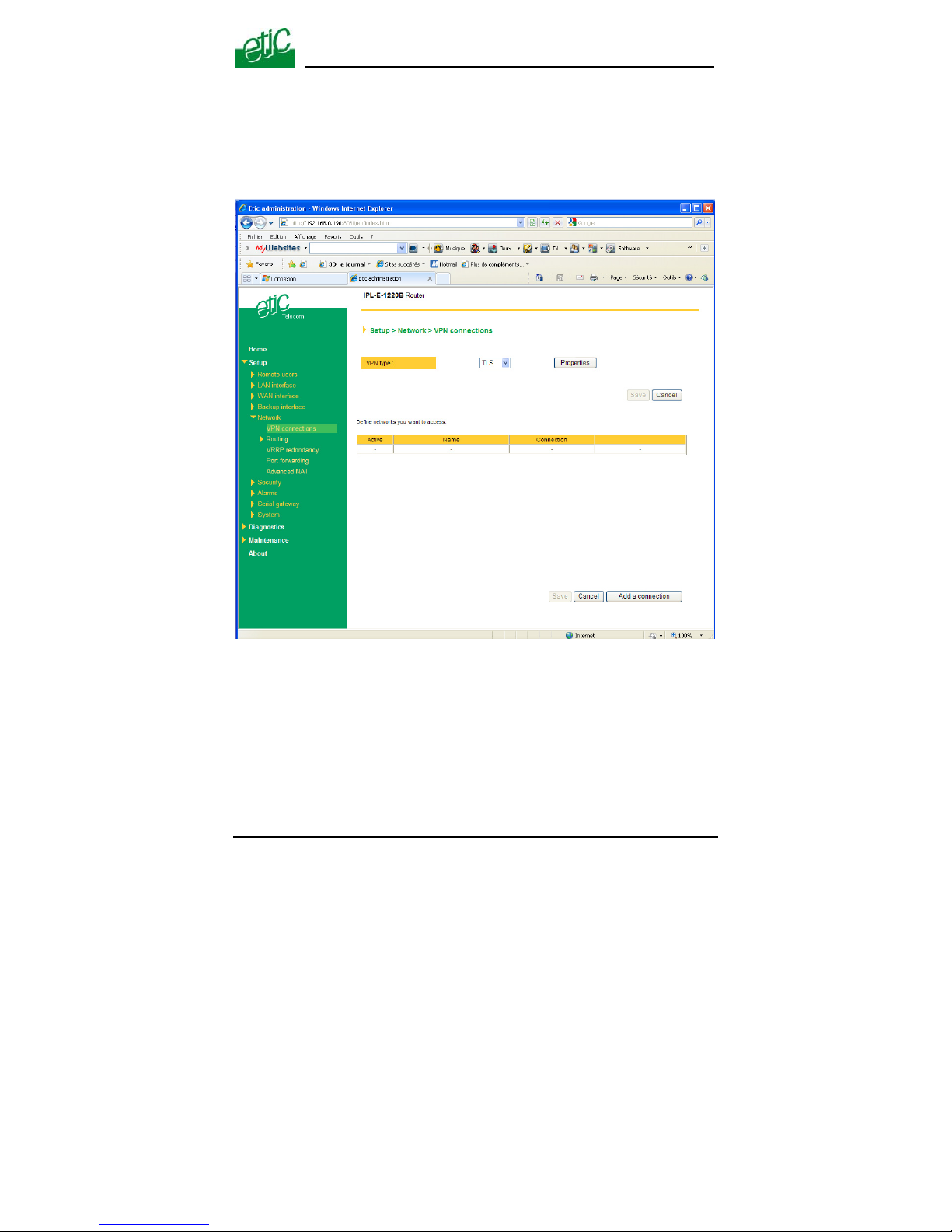
To create VPN connections between routers,
• select the « Set up» menu and then « Network» and then “VPN
connections”.
SIG Router & VPN server User’s guide ref. 9017409-01
Page 23
Page 24
CONFIGURATION
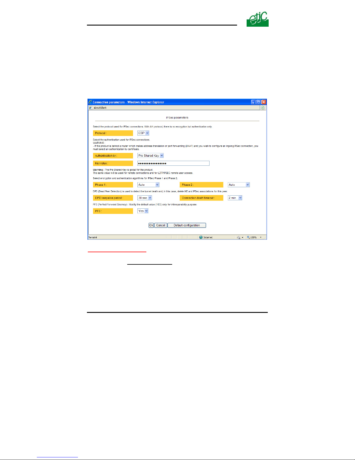
7.2 IPSec VPN connections
7.2.1 Configuring the IPSec protocol
• Select the “Set up” menu, the “network” menu and then ‘VPN
connections”.
• Select the “Ipsec” type of VPN,
• Click “
Properties” .
“ Protocol ” parameter
:
AH ((RFC2402) provides integrity, authentication, replay resistance and
non-repudiation but not encryption.
select AH, if no encryption is required or if NAT traversal is required.
ESP provides the same services plus encryption.
If ESP is selected, an encryption and an authentication protocols must be
selected.
Page 24 User’s guide ref 9017409-01 SIG Router & VPN server
Page 25

CONFIGURATION
SIG Router & VPN server User’s guide ref. 9017409-01 Page 25
“Authentication & encryption key” parameters
:
Authentication an encryption can be carried-out with a pre-shared key or a certificate.
“Pre-shared key” value :
The pre-shared key value applies to all the connections.
The maximum length of the key is 40 characters.
The same preshared key value will be used for remote users L2TP /
IPSec connections.
“Certificate” value
The SIG router is delivered with a certificate stored into the product in
our factory.
To add a certificate, refer to the “Security” menu.
“Encryption and hash algorithm phase 1”
& “Encryption and hash
algorithm phase 2” parameters :
That parameters allow to define the encryption and hash algorithms in use
during the phase 1 of the exchanges between the end-points (VPN setup) and during the phase 2 (data exchange).
The default value is Auto; in that case both end-points will negotiate a
common algorithm.
“DPD request period” parameters
:
A DPD request (also called Keepalive message) is a message sent
periodically by each end-point to the other one to make sure that the VPN
must be left active.
This parameters sets the maximum amount of time (in seconds) between
two of these requests.
“Connection death time-out” parameters
:
This parameter defines the maximum amount of time (in seconds) a VPN
connection will stay established if no traffic or no DPD request message
are received from the remote router.
ATTENTION : Once the parameters of the IPSEC connection have
been selected, click the OK button and then the Save button.
Page 26
CONFIGURATION
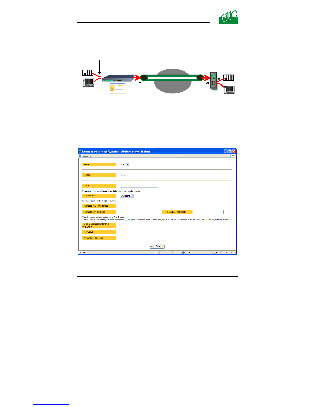
7.2.2 Setting up an outgoing IPSec connection
IP network
VPN
Router
Outgoing
connection
Incoming
connection
Remote LAN
IP address
Remote router
Remote WAN
IP address
LAN
IP address
WAN
IP address
To set up an outgoing VPN connection,
• Come back to the “VPN connections” screen,
• Click the “add a connection” button.
Give a name to the connection and select the “Outgoing” option.
Page 26 User’s guide ref 9017409-01 SIG Router & VPN server
Page 27

CONFIGURATION
SIG Router & VPN server User’s guide ref. 9017409-01 Page 27
‘Remote WAN IP address’ parameter
:
Enter the IP network address and netmask assigned to the remote router
over its WAN interface..
“Remote LAN address
& Remote LAN netmask” parameters :
Enter the IP network address and netmask assigned to the remote LAN.
• Preshared key
If the preshared key used by the connection is the general PSK entered in
the “VPN” menu, no additional parameter has to be entered.
If a particular PSK must be used, complete the configuration of the
connection as explained below.
“Unique PSK for this node” parameter :
Select that option if a particular PSK key has to be used for this
connection.
“PSK value” parameter :
Enter the value of the PSK.
”My WAN address” parameter :
Enter the IP address of the router on the WAN interface.
• Certificate
“My subjectAlt name”
& “Remote subjectAlt name” parameters :
Paste the field "SubjectAltName" of the active certificate of the router you
are configuring and the one the remote router.
Attention : For ETIC certificates, this field is the Email field
Page 28
CONFIGURATION
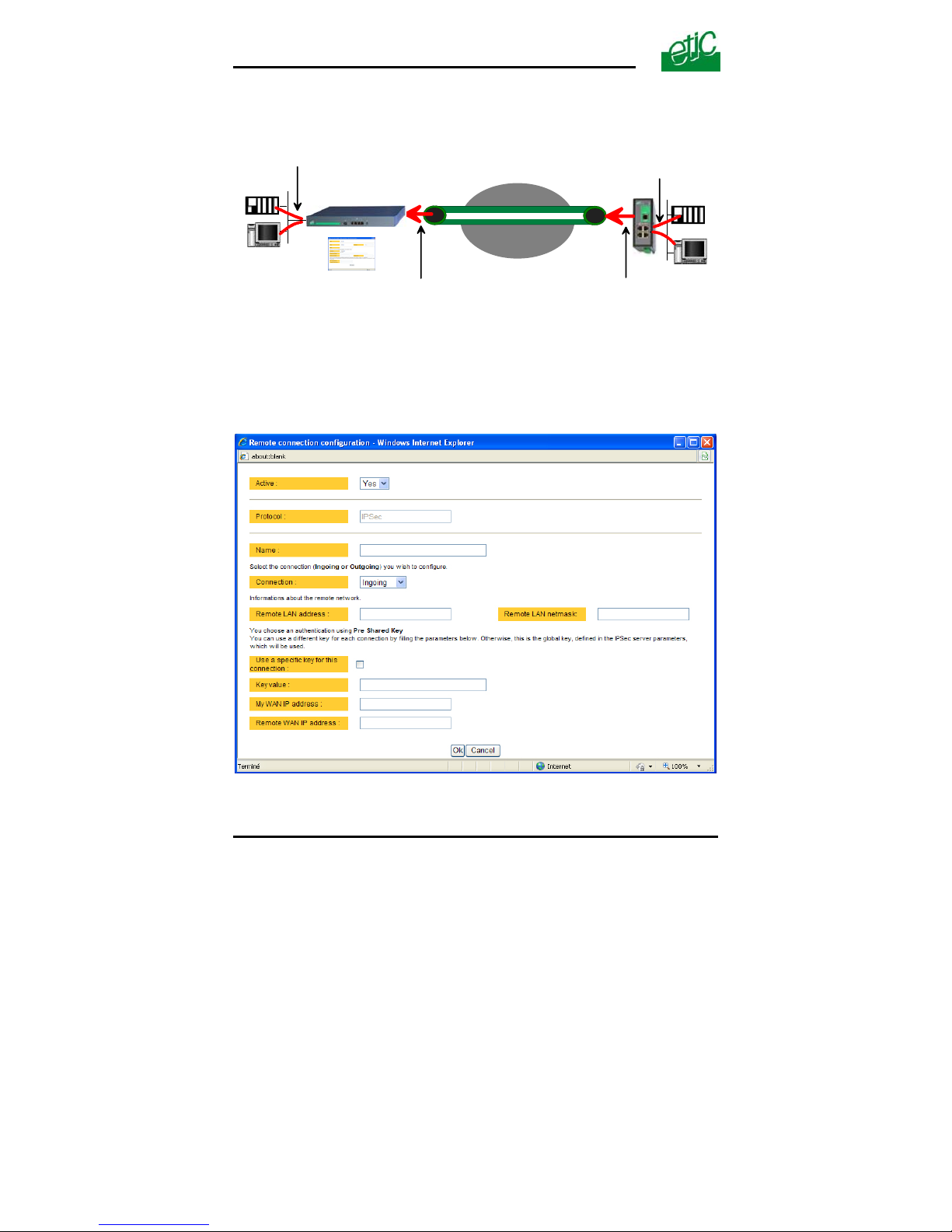
7.2.3 Configuring an ingoing IPSec connection
VPN
Router
Remote LAN
IP address
LAN
IP address
Incoming
connection
Outgoing
connection
Remote WAN
IP address
WAN
IP address
Remote router
IP network
To set an ingoing VPN connection,
• Come back to the “VPN connections” screen,
• Click the “add a connection” button.
Page 28 User’s guide ref 9017409-01 SIG Router & VPN server
Page 29

CONFIGURATION
SIG Router & VPN server User’s guide ref. 9017409-01 Page 29
Give a name to the connection and select the “ingoing” connection
direction option.
“Remote WAN IP address” parameter
:
Enter the IP network address and netmask assigned to the remote router
over its WAN interface.
“Remote LAN address” & “Remote LAN netmask” parameters
:
Enter the IP network address and netmask assigned to the remote LAN.
• Preshared key
If the key used by the connection is the general PSK entered in the VPN
menu, no additional parameter has to be entered.
If a particular PSK must be used, carry out the configuration of the
connection as explained below.
“Use a specific key for this connection” parameter
:
If that option is not selected, the preshared key entered in the VPN
configuration screen will be used by the router.
If that option is selected, enter the specific key.
“My WAN address
& Remote WAN address” parameters :
Enter the WAN IP address of the router and the WAN IP address of the
remote router.
Attention : For ETIC certificates, this field is the Email field
• Certificate
“My subjectAlt name”
& “Remote subjectAlt name” parameters :
Paste the field "SubjectAltName" of the active certificate of the router you
are configuring and the one the remote router.
Attention : For ETIC certificates, this field is the Email field.
Page 30
CONFIGURATION
7.3 TLS VPN connections
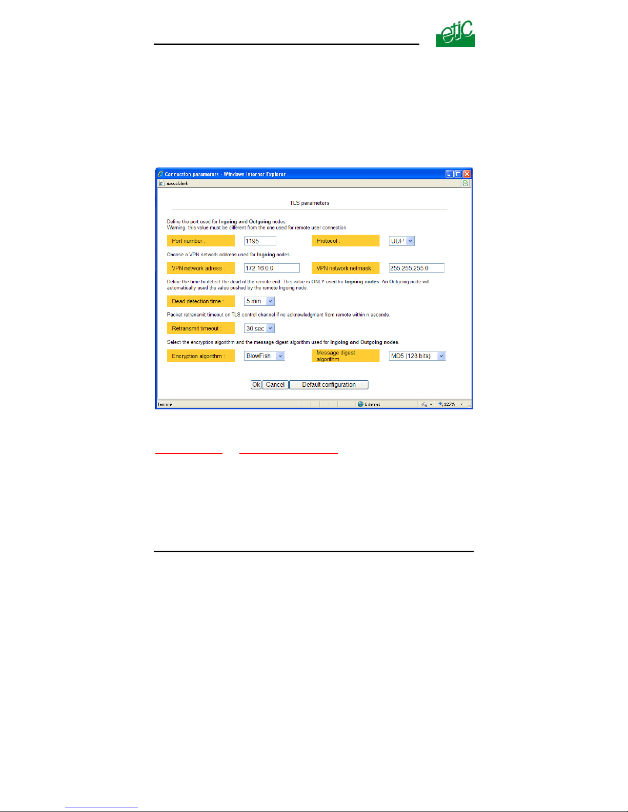
7.3.1 Configuring the TLS-SSL protocol
• Select the “Set up” menu, the “network” menu and then the ‘VPN
connections” menu.
• Select the “TLS” VPN type and click “Properties” .
“Port number”
& “protocol” parameters :
Select the port Nr and the type of level 3 protocol used to transport the
TLS VPN; UDP will be preferred.
Attention :
The port number value must be different from the one used by remote
users.
Page 30 User’s guide ref 9017409-01 SIG Router & VPN server
Page 31

CONFIGURATION
“VPN network address” & “VPN network netmask” parameters :
The TLS VPN server router assigns automatically an IP address to the
VPN client router.
That VPN IP address must not be confused with the WAN interface IP
address.
Attention :
The VPN IP network address field must be different from the WAN
network IP address .
The number of VPN addresses cannot be greater than 255; the netmask
cannot exceed 255.255.255.0.
“Connection death time-out”
parameter :
This parameter defines the maximum amount of time (in seconds) a VPN
connection will stay established before being cleared if no response to the
VPN control message has been received from the remote router.
“Packet retransmit time-out” parameter
:
A control message (also called Keepalive message) is sent periodically by
the VPN server router to make sure that the VPN must be left active.
This parameters sets the amount of time (in seconds) the server will wait
for the response before repeating it.
“Encryption algorithm”
& “Authentication algorithm” parameter :
That parameters allow to define the encryption and hash algorithms in
use.
SIG Router & VPN server User’s guide ref. 9017409-01
Page 31
Page 32
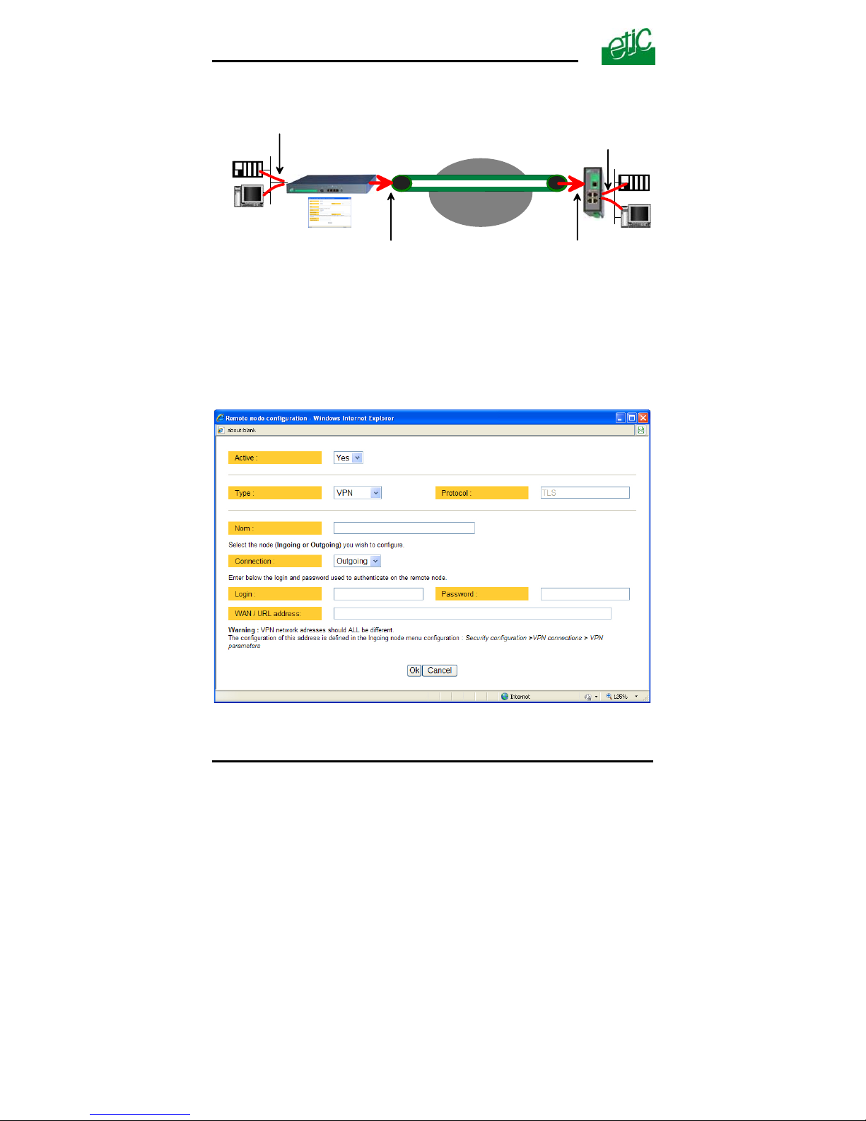
CONFIGURATION
7.3.2 Configuring an outgoing TLS connection 2 Configuring an outgoing TLS connection
IP network
VPN
Router
Outgoing
connection
Incoming
connection
Remote LAN
IP address
Remote router
Remote WAN
IP address
LAN
IP address
WAN
IP address
• Select the “Set up” menu, the “network” menu and then the ‘VPN
connections” menu.
• Select the “Set up” menu, the “network” menu and then the ‘VPN
connections” menu.
• Click the “add a connection” button. • Click the “add a connection” button.
• Give a name to the connection and select the “Outgoing”
connection direction option.
• Give a name to the connection and select the “Outgoing”
connection direction option.
Page 32 User’s guide ref 9017409-01 SIG Router & VPN server
Page 33

CONFIGURATION
SIG Router & VPN server User’s guide ref. 9017409-01 Page 33
“Login & Password” parameter:
Enter the login and password, the router will have to use to authenticate.
Remote WAN IP address / URL parameter
:
Enter the IP address of the remote router or its DNS name.
“Remote WAN IP address” ” parameters
:
Enter the IP network address and netmask assigned to the remote router
over its WAN interface.
Page 34
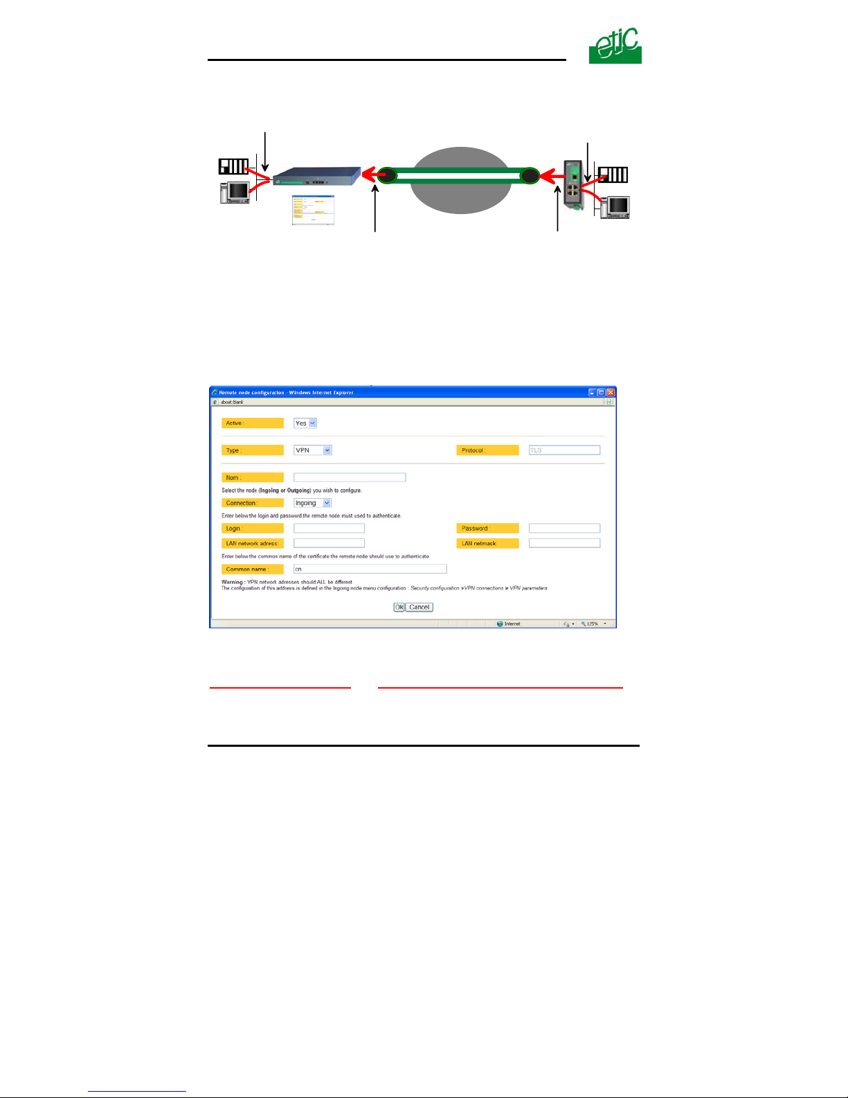
CONFIGURATION
7.3.3 Configuring an ingoing TLS connection
VPN
Router
Remote LAN
IP address
LAN
IP address
Incoming
connection
Outgoing
connection
Remote WAN
IP address
WAN
IP address
Remote router
IP network
• Select the “Set up” menu, the “network” menu and then the ‘VPN
connections” menu.
• Click the “add a connection” button.
Give a name to the connection and select the “ingoing” connection
direction option.
“Remote router Login”
& “Remote router password” ” parameters :
Enter the login and password of the remote router
The remote router has to use that login and password to authenticate.
Page 34 User’s guide ref 9017409-01 SIG Router & VPN server
Page 35
CONFIGURATION
“Remote LAN address” & “Remote LAN netmask” ” parameters :
Enter the IP network address and netmask assigned to the remote LAN.
“Common name” parameters
:
Enter the remote router certificate common name.
Attention : For ETIC certificates, this field is the Email field.
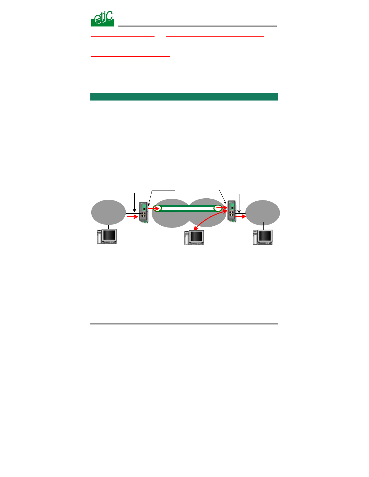
8 Routing functions
8.1 Basic routing function
Once an iP address has been assigned to the R2 router on the LAN
interface and another one on the WAN interface (see drawing hereafter),
the SIG R2 router is ready to route frames …
… between devices connected to the remote LAN network like RL1,
and devices connected to the LAN network like L1 through a VPN;
… between devices connected to the WAN network like W1, and
devices connected to the LAN network like L1
RL1
VPN
WAN
192.168.3.0/24
LAN
192.168.2.0/24
W1
L1
Remote WAN
192.168.4.0/24
R3 router
192.168.2.128
R2 router
192.168.3.128192.168.4.128
192.168.5.128
Remote LAN
192.168.5.0/24
Remark 1 : Firewall rules must be set to authorize WAN to LAN transfer.
Remark 2 : A default gateway address must be entered in each device of
the different networks.
SIG Router & VPN server User’s guide ref. 9017409-01
Page 35
Page 36
CONFIGURATION
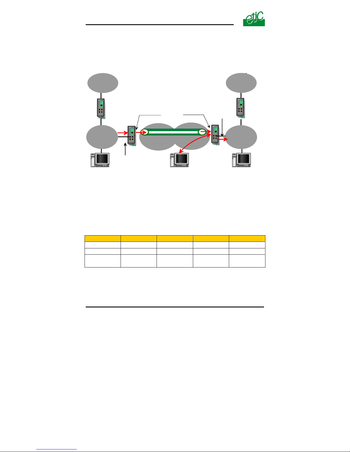
8.2 Static routes
However, the router R2 is not able to route frames between a device like
L1 belonging to the LAN network and a device connected to “network 6”
(see the drawing hereafter).
Network 6
192.168.6.0
network 1
192.168.1.0
192.168.6.24
192.168.1.24
R1 router
R4 router
192.168.5.1
192.168.2.1
192.168.2.128
RL1
VPN
W1
L1
R3 router
192.168.5.128
R2 router
192.168.3.128192.168.4.128
Remote WAN
192.168.4.0/24
WAN
192.168.3.0/24
Remote LAN
192.168.5.0/24
LAN
192.168.2.0/24
In that case, it is necessary to enter the route to that hidden “network 6”;
that route is called a static route.
A static route consists in a table which describes a destination network (IP
address and netmask) and the IP address of the neighbour router through
which an IP packet to that destination must pass.
Router 2 static routes :
Active Route name Destination Netmask Gateway
Yes Network 6 192.168.6.0 255.255.255.0 192.168.5.1
Yes Network 1 192.168.1.0 255.255.255.0 192.168.2.1
Yes Network
Remote WAN
192.168.4.0 255.255.255.0 192.168.5.128
Page 36 User’s guide ref 9017409-01 SIG Router & VPN server
Page 37

CONFIGURATION
SIG Router & VPN server User’s guide ref. 9017409-01 Page 37
Remark :
It is not necessary to enter in the router R2 the static route to the WAN
network nor to the remote LAN network, that routes have been
automatically created by the router respectively when the WAN IP
address has been entered and when the VPN has been configured.
To set a static route,
• Select the “Configuration” menu, the “network” menu the “Routing”
menu and then “Static routes”.
• click the “Add a route” button.
“Destination IP address”
& “netmask” parameters :
Enter the destination network IP address and netmask.
“Gateway IP address” parameters
:
Enter the Ip address of the gateway through which the IP packets
intended for that network must pass.
8.3 RIP protocol
RIP (Routing Information Protocol) is a routing protocol which enables
each router belonging to a network to acquire the routes to any subnet.
The principle is as follows :
Routing table
Each router holds a routing table.
Each entry of the table consists in the destination subnet address and the
adjacent router address leading to that subnet.
Routing table broadcasting :
Each router broadcasts its table.
Routing table update :
Each router updates its own table using the tables received from the other
ones.
Page 38

CONFIGURATION
Page 38 User’s guide ref 9017409-01 SIG Router & VPN server
To enable RIP,
• select the « Set up» menu, the “Routing” menu and then the “RIP”
menu».
• Select the ‘
Enable RIP on LAN interface” and the “Enable RIP on WAN
interface” options.
9 Address and port translation
The SIG provides the capability to replace the original source IP address
and the destination port and IP address in particular situations.
9.1 Port forwarding
The port forwarding function consists in transferring to a particular
device connected to the LAN interface a particular data flow addressed
to the SIG router on its WAN interface.
That function applies only to the frames addressed to the WAN IP
address of the router.
The transfer criteria is the port number; the port number is used as an
additional address field.
When a frame is addressed to the SIG router with a particular registered
port, it is transferred to a particular device connected to the LAN
interface.
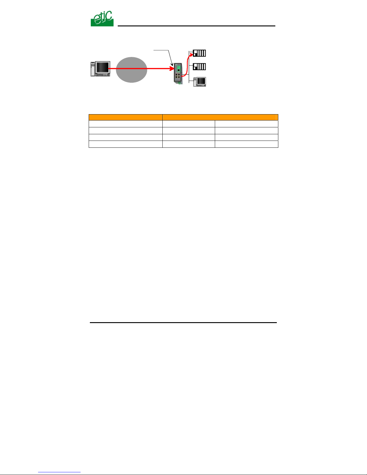
Example :
Let us suppose the PC named “W1” of the WAN network has to send
frames to the device PLC1 of the LAN network
Suppose moreover that the addresses of the LAN network cannot be
used on the WAN network for any reason.
The solution can be to use the Port forwarding function :
When W1 needs to transmit frames to PLC1, it addresses the frames to
the SIG router on a chosen and agreed port.
The router checks the frame, replaces the destination address by the Ip
address of the device on the LAN interface, and eventually changes the
port number.
Page 39
CONFIGURATION
PLC1 192.168.0.15
TCP : 102
PLC2 192.168.0.16
TCP : 502
PC 192.168.0.17
TCP : 80
62.10.10.7
TCP : 102
WAN IP addr. :
62.10.10.7
WAN
network
W1
The port forwarding rule will be
Internet / WAN LAN translation
Service Device Service
102 192.168.0.15 102
502 192.168.0.16 502
80 192.168.0.17 80
To set the Port forwarding function,
• select the “network” menu and then the “Port forwarding” menu.
• Click “Add a DNAT” rule.
9.2 Advanced network address and port translation
9.2.1 Principle
That function consists in replacing the source port and IP address or the
destination port and IP address of particular frames received by the router
on its interfaces according to configured rules.
It applies to all the frames received by the router on any of its two
interfaces except to the IP packets contained in a remote user PPTP or
TLS connection.
It applies as well to frames the destination address of which is the SIG
router itself or to frames the destination IP address is a device belonging
to the LAN subnet, or to the WAN subnet or to another network.
One brings out
the DNAT function which consists in replacing the destination port and IP address.
SIG Router & VPN server User’s guide ref. 9017409-01
Page 39
Page 40
CONFIGURATION
the SNAT function which consists in replacing the source IP address.
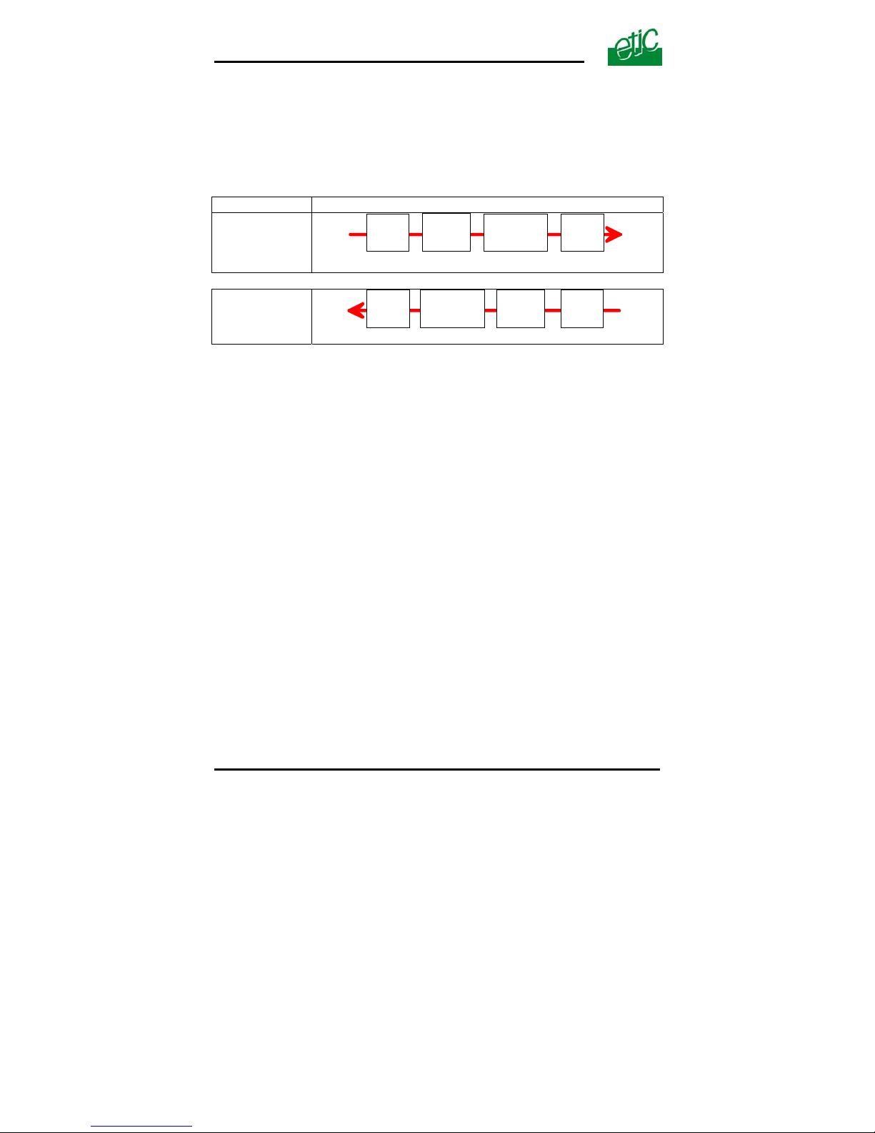
Because the DNAT and SNAT functions modify the IP addresses of the IP
packets processed by the SIG router, and because the firewall filters that
frames, it is very important to understand in which order that different
functions are carried out.
Direction
WAN to LAN
LAN to WAN
Page 40 User’s guide ref 9017409-01 SIG Router & VPN server
DNAT
FIREWALL
SNAT
WAN LAN
Router
LAN
SNAT
DNAT
WAN
FIREWALL
Router
Page 41
CONFIGURATION
9.2.2 Configuration
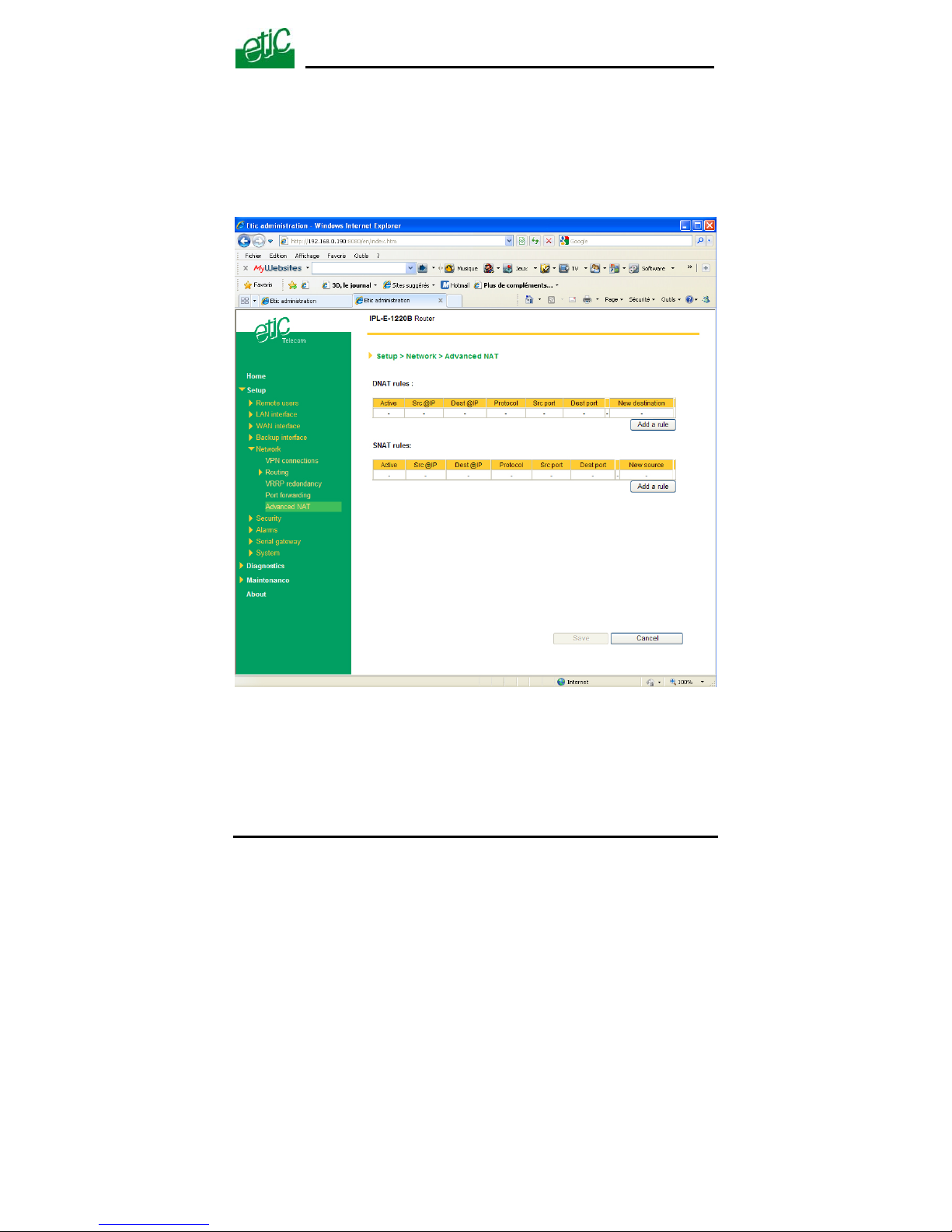
To set the advanced address translation functions,
• select the “Set up” menu, “Network” , and then the “Advanced NAT”
menu.
SIG Router & VPN server User’s guide ref. 9017409-01
Page 41
Page 42
CONFIGURATION
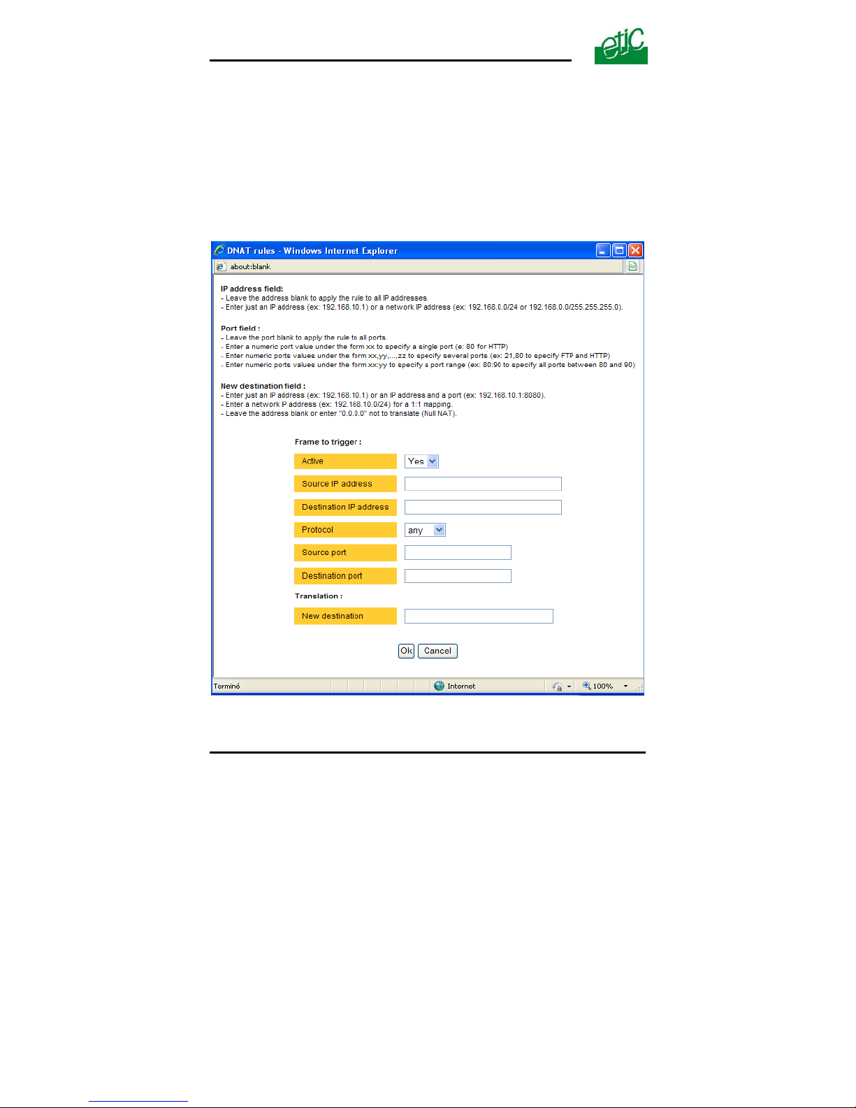
To create a new DNAT rule
• Click “Add a DNAT” rule.
• Select “Yes” to enable the rule.
• Enter the replacement criterion :
Source IP address & Destination IP address.
Protocol (TCP, UDP, …)
Source port & Destination port
• Enter the new destination port number and IP address.
Page 42 User’s guide ref 9017409-01 SIG Router & VPN server
Page 43
CONFIGURATION
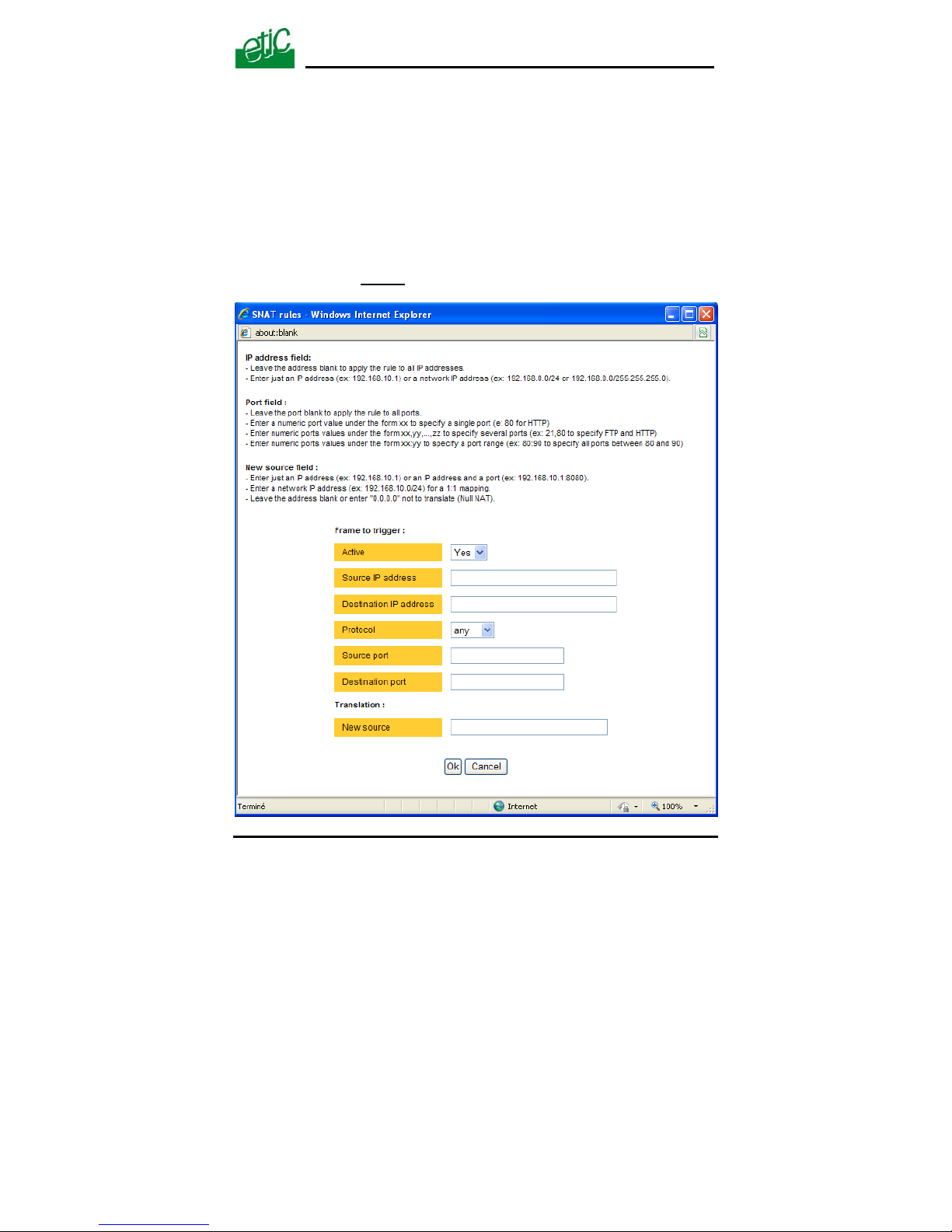
To replace the source IP address & destination port
• Click “Add a SNAT” rule.
• Select “Yes” to enable the rule.
• Enter the replacement criterions :
Source & Destination IP address.
Protocol (TCP, UDP, …)
Source & Destination port
• Enter the new source
IP address.
SIG Router & VPN server User’s guide ref. 9017409-01
Page 43
Page 44

CONFIGURATION
Page 44 User’s guide ref 9017409-01 SIG Router & VPN server
10 VRRP redundancy
10.1 Principle
VRRP is a protocol designed to increase the availability of the default
gateway of a subnet.
Thanks to VRRP, a group of two or more routers can service the hosts of
one subnet instead of only one usually; only one router of that group
actually routes frames; if it fails another one of the group takes its place.
The routers belonging to a VRRP group must be connected to the same
Ethernet segment.
VRRP works as follows :
An usual IP address is assigned to each router of the group.
An additional and common IP address, called the virtual IP address is
assigned to all the routers of the group. This virtual address is the address
which must be stored as the default gateway address in all the host
devices belonging to the subnet.
A priority index is assigned to each router of the group. Using that index,
the routers of the group can elect a master router; the master router is the
one which has the greatest priority code. The other routers are the backup
routers.
The master router is the only one to answer to the ARP requests and
route actually frames. It uses the virtual IP address and the virtual MAC
address If that option has been selected.
In case of failure of the master router, another master router is elected. It
replaces the router in failure. It will use the same virtual IP address and
the virtual MAC address as the previous master router.
The SIG router manages that protocol as well on the LAN and on the
WAN interface.
Page 45

CONFIGURATION
SIG Router & VPN server User’s guide ref. 9017409-01 Page 45
10.2 Configuring VRRP on the LAN interface
To enable and configure VRRP,
• select the “Set up” menu, the “network” menu and then the “VRRP”
menu.
«
Enable VRRP on the LAN interface» parameters :
Tick that checkbox to enable VRRP on the LAN interface.
«
VRRP Id (1-255)» parameter:
Assign an identity code to the routers group between 1 and 255.
The same identity code must be assigned to all the routers of the group.
«Virtual IP address» parameter :
Enter the IP address the elected master router will use to answer to ARP
requests.
«Priority
(1-255)» parameter :
Assign a priority index to the router
The router which has the greatest index will become the master router.
«Use a virtual
MAC address» parameter :
A virtual MAC address can be associated to the virtual IP address.
If that option is selected, the elected master router will answer to ARP
requests by using that virtual MAC address.
That MAC address is 00-00-5E-00-01-XX, where XX is the VRRP Id of the
group coded in hexadecimal.
Page 46

CONFIGURATION
Page 46 User’s guide ref 9017409-01 SIG Router & VPN server
10.3 Configuring VRRP on the WAN interface
To enable and configure VRRP,
• select the “Set up” menu, the “network” menu and then the “VRRP”
menu.
«
Enable VRRP on the WAN interface» parameter :
Tick that checkbox to enable VRRP on the LAN interface.
«
VRRP Id (1-255)» parameter :
Assign an identity code to the routers group between 1 and 255.
The same identity code must be assigned to all the routers of the group.
«Virtual IP address» parameter :
Enter the IP address the elected master router will use to answer to ARP
requests.
«Priority
(1-255)» parameter :
Assign a priority index to the router
The router which has the greatest index will become the master router.
«Use a virtual
MAC address» parameter :
A virtual MAC address can be associated to the virtual IP address.
If that option is selected, the elected master router will answer to ARP
requests by using that virtual MAC address.
That MAC address is 00-00-5E-00-01-XX, where XX is the VRRP Id of the
group coded in hexadecimal.
Page 47

CONFIGURATION
SIG Router & VPN server User’s guide ref. 9017409-01 Page 47
11 Remote users connections service
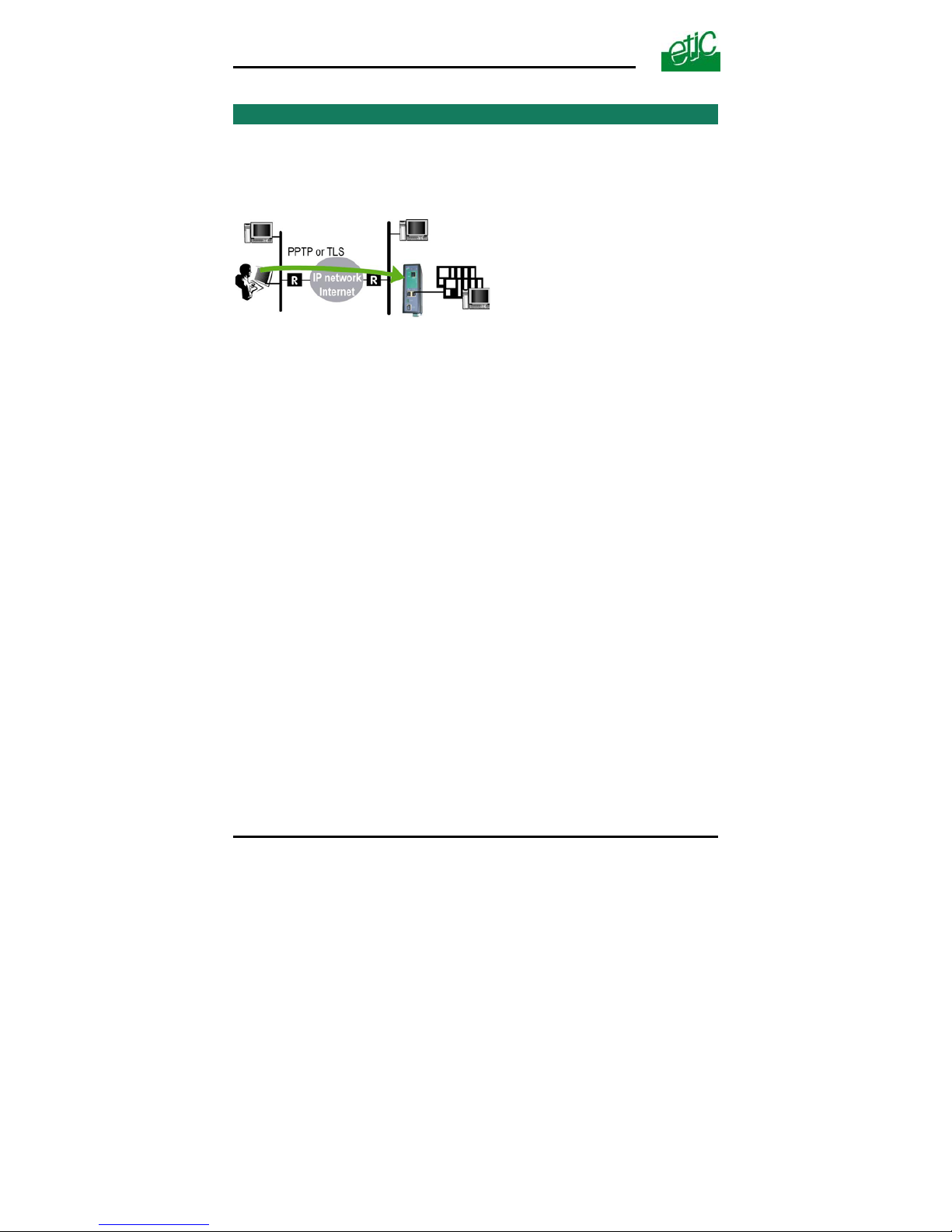
The SIG provides a full remote user connection function called RAS :
• The remote user authenticates using the login, password and
eventually a certificate; the router accepts the connection only if the
remote user belongs to the user list.
• Individual access rights are automatically allocated to the remote user.
• An IP address belonging to the LAN network is automatically assigned
to the remote PC.
• Data are encrypted (TLS and L2TP / IPSec only).
• The connection is logged.
• Moreover, the SIG is compatible with the M2Me_Connect service
when setting a direct connection is not possible.
To set up the remote user connection service, the following steps
must be carried out :
• Step 1 :
Configure a PPTP or TLS or L2TP connection
• Step 2 :
Complete the user list
• Step 3 ::
Define the firewall rules
to limit the rights of the remote users
Page 48
CONFIGURATION
12 Remote users connections
12.1 Principles
A remote user connection is a tunnel set between a remote PC and a
router providing the RAS function (Remote Access Service), like the SIG.
A remote user connection provides security and simplicity advantages :
• The remote user is identified with a login in and password or eventually
a certificate.
• The data is encrypted (TLS or L2TP).
• An IP address belonging to the local network is automatically assigned
to the remote user’s PC.
The SIG manages PPTP and TLS or L2TP remote connections.
Only one type can be selected. It will apply to all the remote users
connections.
A PPTP is the simplest type of remote user connection; data is not
encrypted.
The remote user can be identified only with a login and password.
A TLS connection provides encryption; moreover; the remote user can be
identified with a log in and password and with a certificate if necessary.
Page 48 User’s guide ref 9017409-01 SIG Router & VPN server
Page 49

CONFIGURATION
12.2 Configuring a TLS connection
The M2Me_Secure software provided by ETIC TELECOM is a Windows
TLS client software.
Installed on a PC running Windows XP or Seven, M2Me_Secure makes
TLS connections from a remote PC to the SIG easy; moreover it includes
a connection book in such a way one just need a click to connect to a
remote site.
We describe hereafter how to configure the router and the M2Me_Secure
software to set a TLS VPN between both.
Step 1 : Router configuration
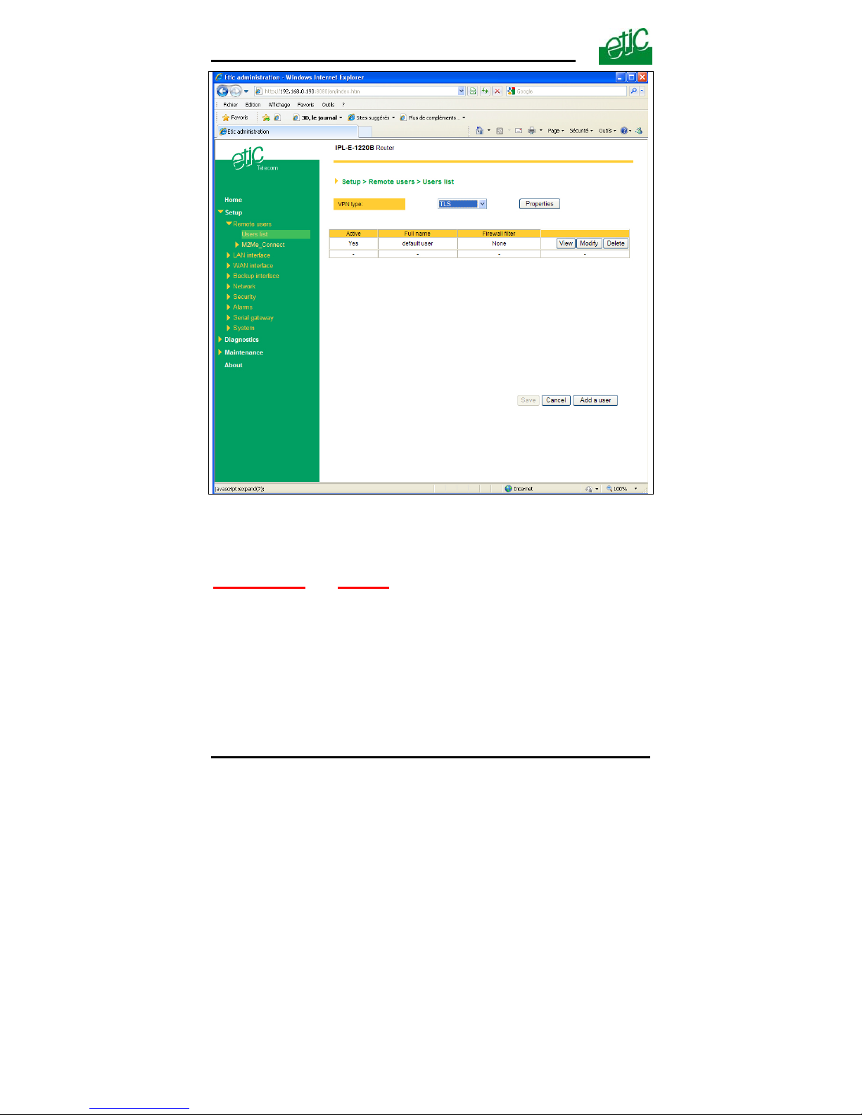
To configure a remote user TLS connection,
• select the “Set up” menu, the “Remote users” menu and then the
“User list” menu.
SIG Router & VPN server User’s guide ref. 9017409-01
Page 49
Page 50
CONFIGURATION
• Select the VPN type “ TLS”.
• Click the “Properties” button and set the parameters.
”Port number”
& “Protocol” :
Select the port Nr and the type of level 3 protocol used to transport the
TLS VPN; UDP will be preferred.
Attention :
The selected port number assigned to the remote users connections
must be different from the one used for VPN connections between routers
if such VPN connections have been configured.
Page 50 User’s guide ref 9017409-01 SIG Router & VPN server
Page 51

CONFIGURATION
SIG Router & VPN server User’s guide ref. 9017409-01 Page 51
“Remote Users authentication” parameters :
Authentication an encryption can be carried-out with a pre-shared key or a
certificate.
If the “Login/password” is selected, the remote user is authenticated
with a login and a password.
If the “Login/password and Certificate” value is selected, the
remote PC is authenticated with the certificate and the user with a
login and password. In that case, the PC certificate must be stored in
the user list.
«Encryption algorithm» & «Message digest algorithm» parameters :
Leave the default values.
Step 2 : Configure the M2Me_Secure software
For detailed information, refer to the M2Me_Secure manual.
• Click « Menu » and then « New site ». The Site configuration
window is displayed.
• Select the « General » tab and enter a site name.
• Select the « Connection » tab; select the option “That site can be
reached through the Internet.
• In the field « Host name or IP address », select the router IP address
or DynDNS name or DNS name.
• Select the « Advanced tab » ; select the level 3 protocol (UDP or
TCP), the port number and the encryption algorithm.
These parameters must have the same values must in the PC and in the
router.
Page 52
CONFIGURATION
12.3 Configuring a PPTP connection
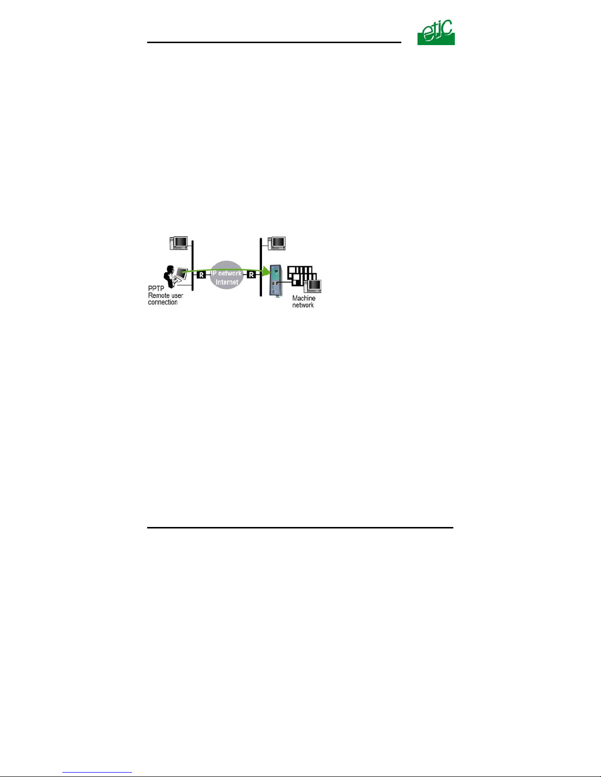
We describe hereafter how to configure the router and the PC to set a
PPTP remote user connection between them.
Step 1 : Router configuration
• select the “Set up” menu, the “Remote users” menu and then the
“User list” menu.
• Select the VPN type “ PPTP”.
Remark : The “properties” button allows to modify the authentication
protocol; leave the default configuration if the PPTP client is a PC running
Windows.
Step 2 : Set a PPTP connection on the PC side.
Page 52 User’s guide ref 9017409-01 SIG Router & VPN server
Page 53
CONFIGURATION
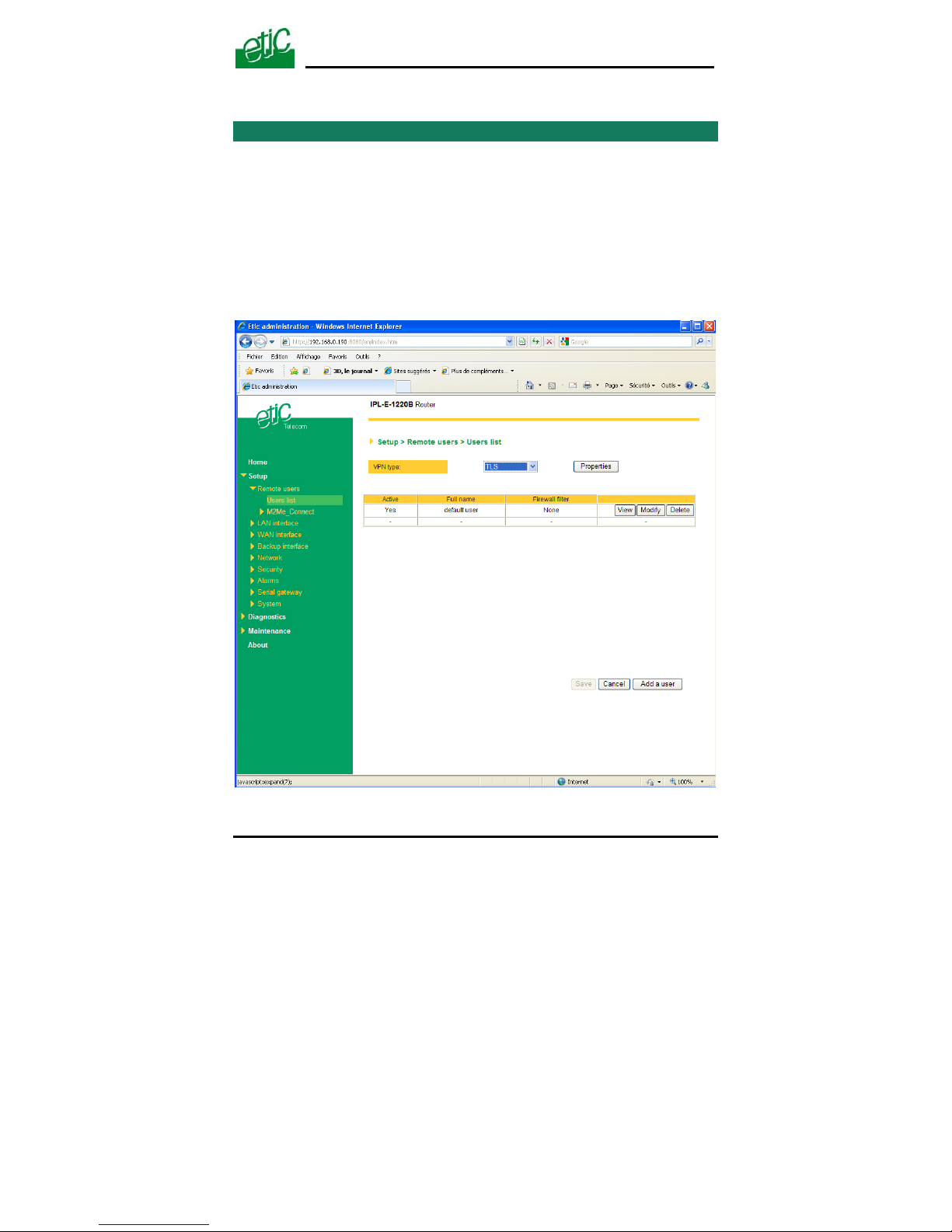
13 Users list
The user list registers 25 authorised remote users forms.
Each user form stores the identity of the user (Login and password), his
email address to send alarm emails and the filter assigned to him.
To display the user list,
• select the “Set up” menu, the “Remote users” menu and then the
“User list” menu.
SIG Router & VPN server User’s guide ref. 9017409-01
Page 53
Page 54
CONFIGURATION
Attention :
Coming from factory, a default user is registered; his login is admin
and
the password is also admin
. After the test phase, we advise to modify
these login and password.
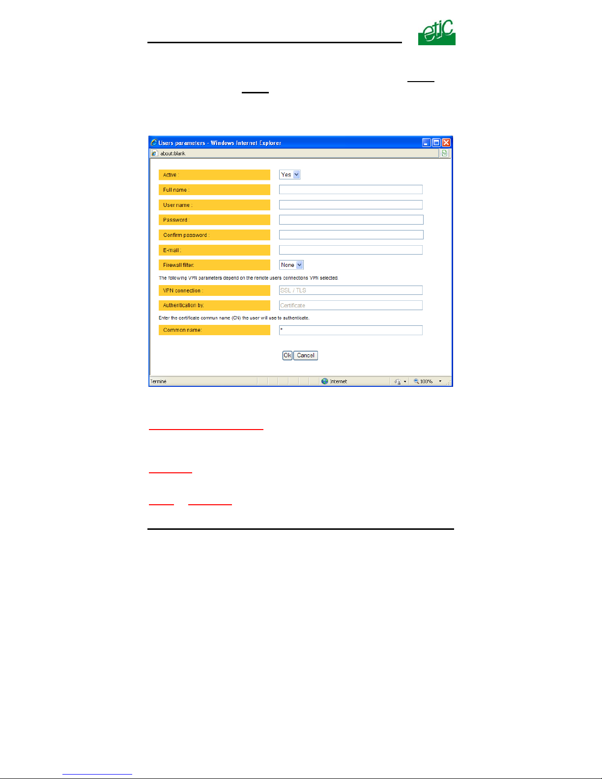
To add a user form
• Click the “add a user ” button
“ Active (value Yes or NO)
” :
Select “No” if you want to prevent the user to access the network.
Select “yes” to authorize the user to access the network.
Full name
:
It is the name displayed in the user list.
Login
& password
The login and the password will have to be entered by each user at the
beginning of the remote connection.
Page 54 User’s guide ref 9017409-01 SIG Router & VPN server
Page 55

CONFIGURATION
SIG Router & VPN server User’s guide ref. 9017409-01 Page 55
E-mail
:
The SIG will send an email to that address in two situations :
Alarm email : the SIG sends an alarm email to the defined user If the input
1 is closed or opened (if that option has been set).
Internet connection email : Once connected to the Internet, the SIG will
send to the demanding user an email containing the dynamic IP @
assigned to the SIG by the provider. (See OPERATION chapter).
Firewall filter
:
Select a filter in the list.
A filter defines a domain of the local network.
Thus, once assigned to a user, a filter limits his or her access rights.
Page 56

CONFIGURATION
Page 56 User’s guide ref 9017409-01 SIG Router & VPN server
14 Firewall
14.1 Overview
The firewall filters IP packets between the WAN and the LAN interface of
the SIG router. It is divided in 3 particular filters :
• The remote users filters
The function of the remote users filters is to limit the IP domain an
authenticated remote user can reach when he connects to the SIG router
through the Internet.
The remote users filters filter the destination IP address and port number
of the IP packets included inside a PPTP or TLS or L2TP remote user
connection.
Thus the IP addresses checked by the remote users filters are LAN IP
addresses.
25 remote users filters can be created and assigned individually to each
of the users declared in the user list.
The source IP address of the packets is not checked by the remote users
filters because the filters apply to the remote users connections according
the login and password of the remote user checked when the remote user
connection is set.
• The main filter
It filters IP packets whether carried inside one of the VPNs or outside a
VPN.
The main filter checks source and destination IP addresses and the
source and destination ports.
The main filter does not check the IP packets included in a remote user
connection. That packets are checked by the remote users filter.
The main filter does not check the IP packets defined in the “Port forwarding” table. That
packed are directly forwarded to the defined device (see Port forwarding
).
• The deny of service filter is made to usual attacks coming from
the Internet. That filter cannot be configured.
Page 57
CONFIGURATION
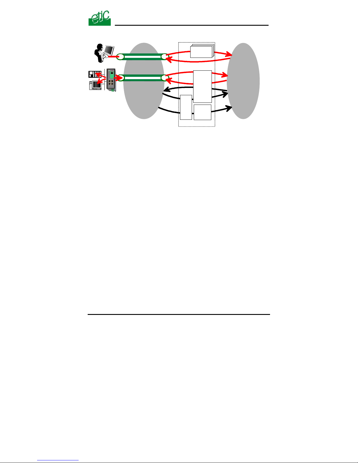
The firewall of the SIG firewall can thus be represented by the drawing hereafter :
VPN between routers
WAN
LAN
Users
filters
Main
filter
FIRE-WALL
DoS
filter
Port
forwarding
Remote user connection
SIG Router & VPN server User’s guide ref. 9017409-01
Page 57
Page 58

CONFIGURATION
Page 58 User’s guide ref 9017409-01 SIG Router & VPN server
14.2 Main filter
The main filter applies to all the IP packets except to the ones included in
remote users connections.
To recognize a TLS remote user connection, the router detects the port
number.
14.2.1 Main filter Overview
• Main filter structure
For a better organisation, the main filter is divided in two tables; both
having the same structure.
The “VPN” filter : It filter the packets transmitted inside the VPNs.
The “WAN” filter : It filters the packets transmitted outside the VPNs
Each of that two filters is made of
a filter policy
and
a filter table each line of which is a filter rule
• Main filter default policy
The default policy is the decision which will be applied if a packet does not
match any of the rules of the filter.
The WAN to LAN and the LAN to WAN traffic are regarded separately
because the decision can be opposite for a packet coming from the WAN
or coming from the LAN :
WAN to LAN : The default policy can be “Accept” or “drop”.
LAN to WAN : The default policy can also be “Accept” or “drop”.
For instance, if the default policy assigned the WAN to LAN traffic is
“drop”, it means that an IP packet which does not match any of the rules
of the main filter will be rejected.
Page 59

CONFIGURATION
SIG Router & VPN server User’s guide ref. 9017409-01 Page 59
• Main filter table
The main filter is a table, each line being a rule.
Each rule of the filter is composed a several fields which defines a
particular data flow and another field which is called the action field.
The fields which define the data flow are :
Direction (« WAN to LAN » or « LAN to WAN »),
Protocol (TCP, UDP…),
IP@ & port number, source & destination.
The Action field can take two values
Accept : To authorize the data flow to be forwarded to the router interface.
Drop : To drop the packet which matches the rule.
• How does the main filters works
When the firewall receives a packet, it checks if it matches the first rule..
If it does, the decision is applied to the packet according to the “Action” field.
If it does not, the firewall checks if it matches the second rule; and so on.
If the packet does not match any of the rules of the table, the default policy is applied to
the packet (drop or reject).
Page 60
CONFIGURATION
14.2.2 Configuring the main filter
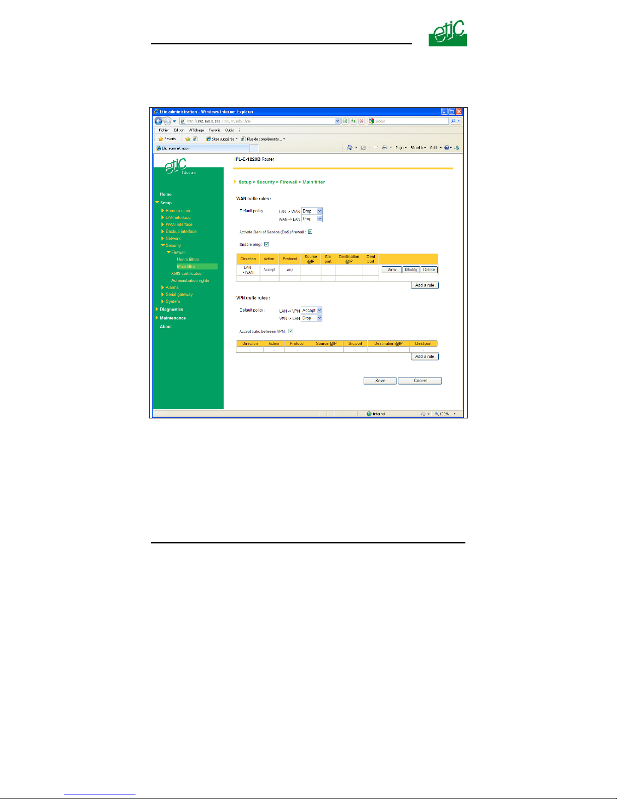
Select the “Security” menu and then “Firewall” and “Main filter”.
The “Main filter” page is divided in two parts :
WAN traffic rules :
The first part, entitled “WAN” traffic rules, is made to define how the IP
packets not carried in a VPN, have to be filtered.
VPN traffic rules :
The second part, entitled “VPN traffic rules” allows to define how the IP
packets carried inside the VPNs have to be filtered.
Page 60 User’s guide ref 9017409-01 SIG Router & VPN server
Page 61

CONFIGURATION
SIG Router & VPN server User’s guide ref. 9017409-01 Page 61
Configure successively the WAN traffic rules using the same method.
Step 1 : Select the default policy
“LAN to WAN” parameter
:
That parameter sets what the filter will decide if an IP packet coming from
the LAN does not match any f the rules of the filter :
If the value “Accept” is selected, the IP packet will be transmitted to the
VPN.
If the value “Drop” is selected, the IP packet will be rejected.
“WAN to LAN” parameter
:
That parameter sets what the filter will decide if an IP packet coming from
the WAN does not match any f the rules of the filter :
If the value “Accept” is selected, the IP packet will be transmitted to the
LAN.
If the value “Drop” is selected, the IP packet will be rejected.
The cautious default policy is to choose the value “Drop”; at the
opposite, if the value “Accept” is selected, a frame which does not match
any of the rules of the filter is transmitted.
Step 2 : Add a rule to the filter
Click the “add a rule” button.
“Direction” parameter
:
Select the direction of the data flow to which the rule applies.
“Action” parameter
:
Select the value “Accept” if the IP packet has to be transmitted in the
selected direction.
Select the value “Drop” if the IP packet has to be rejected.
“Protocol” parameter
:
Select the level 3 protocol concerned.
“Source IP address”
& “Source port” parameters :
Enter the value of the source IP address and the source port number.
It is possible to enter a range of source IP addresses and not a single IP
address by selecting a netmask value from 1 to 32; It is the number of
binary 1 of the netmask; for instance, the value 24 means 255.255.255.0;
the value 16 means 255.255.0.0.
Page 62

CONFIGURATION
Page 62 User’s guide ref 9017409-01 SIG Router & VPN server
”Destination IP address”
& “destination port” parameters :
Enter the value of the destination IP address and the destination port
number. Select the netmask value.
14.3 Remote users filters
A remote user filter applies to the IP packets received inside a remote
user connection.
25 remote user filters can be configured and assigned individually to each
of the users declared in the user list.
A remote user filter is a table of destination port numbers and IP
addresses belonging to the LAN network
.
Once a remote user is connected to the SIG router, the router applies the
filter assigned to him (see the remote user form).
According to his identity (Login and password, he will thus only access to
the IP domain defined by the filter.
Example :
Filter name : Access to the device PLC1 (html and modbus)
Filter policy : All is forbidden except what we specify
Rules list
Action Device Service
Allow PLC1 192.168.0.12 80
Allow PLC1 192.168.0.12 Modbus 502
A filter must be assigned at least to one user to become enabled.
Step 1 : Complete, if necessary, the list of services
Remark : The main services (html, ftp, modbus) are available from
factory; for that reason, most of the time, that step can be skipped.
• Select the menu “system” and then “service list” The list of TCP ports
is displayed.
• Click « add a service ».
• Enter the label of that the new service, assign a protocol (udp, tcp,
icmp) and a port number.
• Save. The list is updated.
Page 63
CONFIGURATION
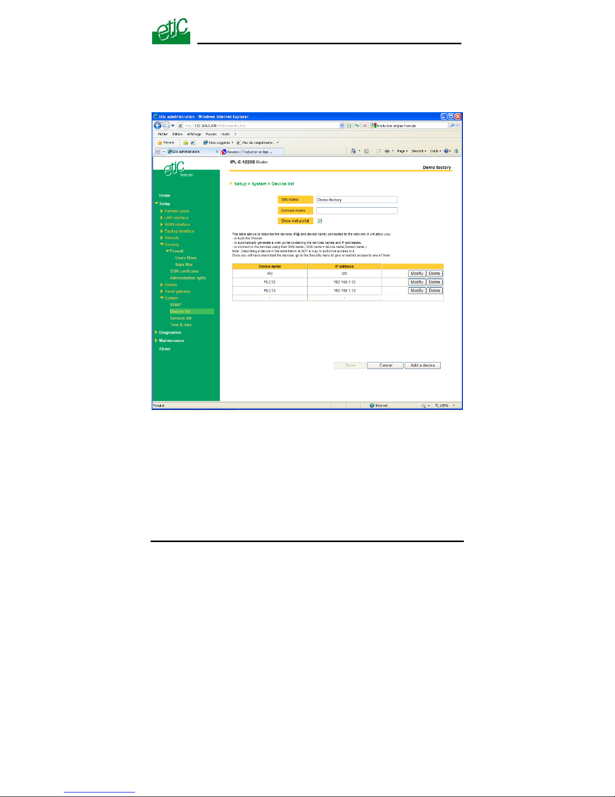
Step 2 : Enter the list of devices of the LAN network
• Select the «System» menu, then «Devices list».
The list of the devices of the LAN network is displayed.
• Click « add a device ».
• Assign a label and an IP address to the device and click OK.
SIG Router & VPN server User’s guide ref. 9017409-01
Page 63
Page 64
CONFIGURATION
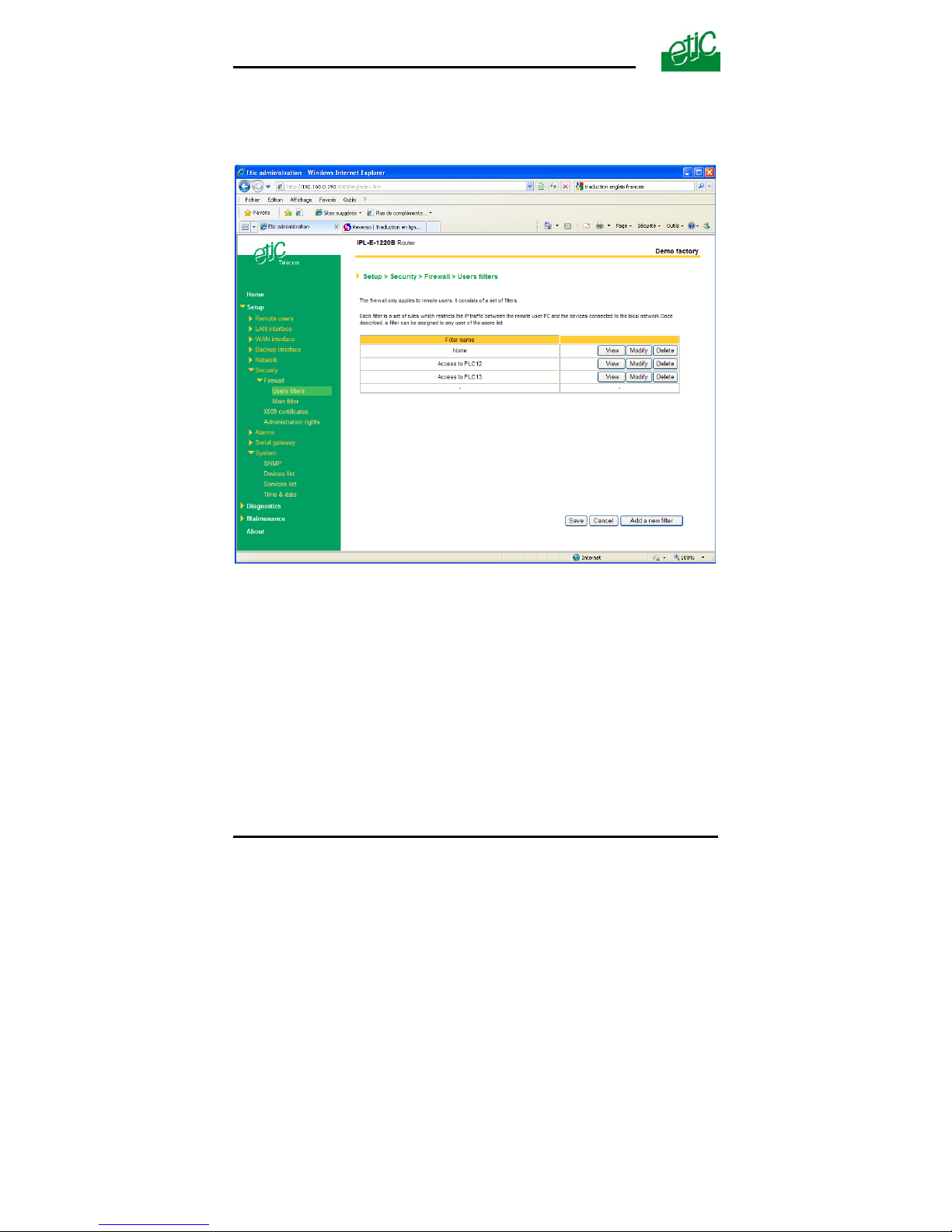
Step 3 : Build a remote user filter
• Select the « security» menu, then « firewall» and then «Filter list»
The users filters list is displayed.
Page 64 User’s guide ref 9017409-01 SIG Router & VPN server
Page 65
CONFIGURATION
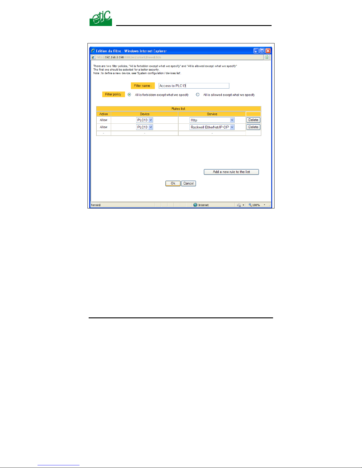
• Click « add a new filter ».
• Assign a name to the new filter.
• Choose the policy ; « All is forbidden except what we specify » is the
advised policy.
• Click « add a new rule to the list ».
• Select a device among the ones which have been stored and a
service (also called port).
• Add other rules if necessary.
• Click OK when the filter is complete ; the updated filter list is
displayed.
SIG Router & VPN server User’s guide ref. 9017409-01
Page 65
Page 66

CONFIGURATION
Page 66 User’s guide ref 9017409-01 SIG Router & VPN server
Step 4 : Assign a filter to each user
• Select the « Remote user» and then « User list ».
• Select a user to which you want to assign a filter ; and click modify ;
the user window is displayed.
Assign a filter to the user ; click OK and save.
Page 67

CONFIGURATION
SIG Router & VPN server User’s guide ref. 9017409-01 Page 67
15 Advanced functions
15.1 Adding a certificate
Coming from the factory, the SIG router includes a certificate delivered by
ETIC TELECOOMUNICATIONS acting as a certification authority.
That certificate can be used to set a VPN between two routers.
Two SIG routers can set a VPN with one another using certificates only if
the certificates have been provided by the same authority.
Additional X509 certificates, provided by ETIC Telecommunications or
not, can be downloaded into the router.
To import a new certificate, the file extension can be PKCS#12 with a
password or PEM.
Even if more than one certificate have been downloaded into the SIG
router, one certificate can be used for all the connections.
15.2 SNMP
The SIG router is able to send snmp traps when alarms occur.
Activation
:
If that option is selected, the router will send an SNMP trap if an alarm is
detected.
SNMP network management IP address :
Enter the IP address of the management platform
SysName
& SysLocation :
That fields allow to identify the source device.
Example :
Sysname : etic
Syslocation : France
Product start-up
:
If that option is selected, the router will send an SNMP trap each time it
will connect to the Internet
Page 68
CONFIGURATION
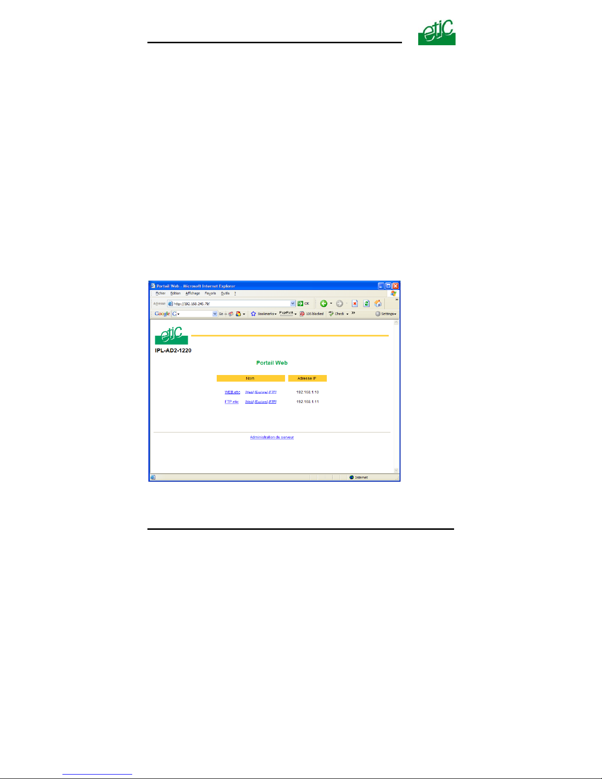
15.3 Configuring the web portal
The web portal in an html page; it displays a list of devices connected to
the LAN. Each line of the list is made of the device name, its IP address
and three links :
The html link : To go directly to the web server of the associated
machine.
The « explore » link : To explore the HD of the associated machine, if
it is a Windows machine.
The « ftp » link : To explore the files of the associated device.
If the we portal option has been selected (see below), the web portal page
is displayed when the remote user launches the navigator and enters the
Ip address assigned to the SIG router. In that case, the administration
server, usually can be displayed at the same address but at the port
number 8080 instead of 80 when the web portal page option is not
selected.
Page 68 User’s guide ref 9017409-01 SIG Router & VPN server
Page 69

CONFIGURATION
SIG Router & VPN server User’s guide ref. 9017409-01 Page 69
15.4 Configuring the DNS server
For domain names resolution, the SIG can behave like a domain name
server or a domain name relay.
DNS server :
A domain name server is a networking device which is able to associate a
label (etictelecom.com for instance) with an IP address.
That function allows a client device to send a request to a network
equipment referring to a domain name as if it was the actual IP address of
the destination device.
The SIG router is able to resolve any domain name composed with the
name of one of the devices entered in the devices list followed the site
name which is entered at the top of the devices list.
DNS relay :
The SIG router behaves also like a DNS relay; any DNS request it
receives from the LAN, which cannot be resolved because the device is
not registered in the devices list, will be transferred to the internet to be
resolved.
That function can be carried out only if the SIG IP address is pointed out
as the main DNS server of the devices of the LAN.
That function is efficient in particular when a device connected to the LAN
has to send emails through the Internet.
Page 70

Page 71

MAINTENANCE
SIG Router & VPN server User’s guide ref. 9017409-01
Page 71
1 Diagnostic
The html server provides extended diagnostic functions.
Select the Diagnostic menu and then the appropriate sub-menu.
• Log sub-menu:
The log displays the last 300 dated events :
ADSL, VPN and users connections and disconnections,
power on,
Serial gateway events.
• Network status sub-menu and then status sub-menu :
That screen displays the current status of the LAN interfaces and of the
Internet connection :
LAN interfaces :
That part of the page shows the data of the LAN interface :
MAC address,
Ethernet mode (10 /100, half or full),
IP address.
WAN interface :
That part of the page shows the data of the Internet interface :
MAC address,
Ethernet mode (10 /100, half or full),
IP address,
DNS servers addresses
Default gateway
• VPN sub-menu :
That menu displays the table of the VPN (remote user connections and
remote routers connections) which are established.
• Ping :
That screen enables to send a ping frame to an IP address.
Page 72

MAINTENANCE
Page 72 User’s guide ref 9017409-01 SIG Router & VPN server
2 Saving the parameters to a file
Once a product has been configured, the parameters can be stored and
restored when necessary.
To save the parameters,
• Select the “System” menu and then “Save restore”,
• Click the ”Save” button
• Select the location to store the file and give a name to the file.
The file suffix is “.bin”.
To restore the parameters,
• Select the “System” menu and then “Save restore”,
• Click the “browse” button and select the parameters file,
• Click the “Load” button and confirm to restart the product.
Attention : A parameters file can only be restored towards a product
having the same firmware version.
3 Updating the firmware
Step 1 : Before starting, you need,
a PC with a Web browser and an Ethernet cable;
the FTP server software which can be downloaded from the « firmware
page » of the ETIC « download area » web server.
Step 2 : Download the release of the firmware from our download area to your PC
Step 3 : Prepare the PC
Check the Ip address of the PC is compatible with the one of the router.
Connect the router to the PC.
Launch the TFTP server (tftp32.exe) software and select the new release
(L026xxx/img) by using the "Browser" button.
Click on "Show dir" to check the files of the directory : rfsmini.tgz,
rootfs.bin, u-boot.bin and uImage.
Page 73

MAINTENANCE
SIG Router & VPN server User’s guide ref. 9017409-01 Page 73
Step 4 : Update the firmware
Launch the web browser
Enter the IP address of the ETIC product ; the home page of the ETIC
configuration server is displayed.
Select the "System" menu and then " firmware Update". In the field "IP
address of the TFTP server", enter the IP address of your PC.
Note : The IP address of the PC is written in the field "Server Interface" in
the TFTP server windows.
Click "Save" and then "Update".
The first file should begin to be downloaded from the PC to the router.
During the operation, the led blinks
When the download is finished, the product automatically reboots.
To be sure the new release has been installed, go to "About" in the
administration web page of the IP product.
Step 5 : Restore the default configuration
• Select the “Maintenance” menu and then the “Save / restore” menu.
• Click the “Restore default configuration” button.
Page 74

MAINTENANCE
Page 74 User’s guide ref 9017409-01 SIG Router & VPN server
Page 75

APPENDIX 1
HTML administration server
SIG Router & VPN server User’s guide ref. 9017409-01
Page 75
1/ Set up menu
Remote users To assign an ID and PWD to each authorized user and set
their rights
To set the M2Me service
LAN interface To enter the IP @ of the router on the LAN interface.
To enter the IP @ assigned to the remote users
To set up the Ethernet interfaces
To set up the DHCP server on the LAN interface
WAN interface To enter the IP @ of the router over the WAN interface.
Network To configures the VPNs
To enter static routes and enable the RIP protocol
To set up the VRRP redundancy protocol
To set up port forwarding
To set up advanced Ip addr. translation functions
Security To set the firewall rules (User filter and main filter)
To add a certificate
To restrict access to the administration server
Alarm To set up alarm SNMP traps
To set up alarm emails
System To set up SNMP parameters
To enter the devices list
To update the service list
To update time and date
Page 76

APPENDIX 1
HTML administration server
Page 76 User’s guide ref 9017409-01 SIG Router & VPN server
2/ Diagnostic menu
Log To display the events ( VPN connections, user connections..)
Network status Interfaces status : @ MAC, @IP, ADSL, VPN
VPN status
Routing tables
Tools To send Pings from the router
Advanced To store the internal report to a disk for diagnostic purposes
3/ Maintenance menu
Firmware update To update the firmware
Save / restore To save or restore a configuration file
.To restore the factory configuration
Reboot To restart he router
4/ About menu
To display the certificate “product key”
To display the firmware version
Page 77
APPENDIX 2
VPN basic mechanisms
1 Overview
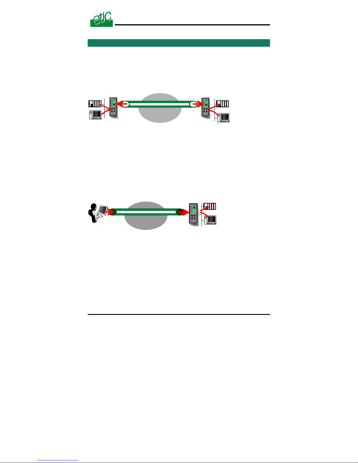
VPN is the acronym for « virtual private network » ; it is a mechanism
which allows to connect safely 2 networks together, or 1 remote PC and
one network, through a network eventually not intrinsically safe.
VPN between two networks
Réseau IP
VPN
Router
VPN
end-point
Router
VPN
end-point
Once a VPN has been set between the two routers , any device of the
first network can communicate with any device of the second one as if the
two routers were directly connected with an Ethernet cable.
VPN between a remote PC and a network
VPN
VPN
end-point
VPN
end-point
IP network
Router
SIG Router & VPN server User’s guide ref. 9017409-01
Page 77
Page 78

APPENDIX2
VPN basic mechanisms
Page 78 User’s guide ref 9017409-01 SIG Router & VPN server
2 Functions
A VPN provides the functions described hereafter :
Authentication
The VPN ensures that the party with which the communication is set is
actually the one it claims to be.
Data integrity
The VPN mechanism ensures that information being transmitted over the
public Internet is not altered in any way during transit
Confidentiality
A VPN protects the privacy of information being exchanged between
communicating parties.
3 Operation
Authentication phase
The first operation the end-points carry out is authentication.
2 levels of authentication can be performed using a VPN :
Device level authentication
A code is stored in each end-point (i.e. router or PC); it can be a Key
or a certificate delivered by a certification authority.
During the initial phase, the two end-point exchange their codes; each
party checks that the other party code is valid.
User level authentication
The SIG router holds a user list; once a VPN has been set with the
remote user PC, the remote user identification code and password is
checked.
Encrypted tunnel transmission phase
Once the end-points have exchanged and checked each other identity
code, they set the VPN tunnel.
It is an IP packets exchange; the source and destination IP addresses
are the end-points.
That tunnel encapsulates the encrypted IP data flow transmitted between
any of the devices connected to each end-point.
Page 79

APPENDIX 2
VPN basic mechanisms
SIG Router & VPN server User’s guide ref. 9017409-01 Page 79
VPN clearing
Periodically, each router (or at least the VPN server router) sends to the
other one a control message to check the VPN must remain established.
If no response is received from the other party, the VPN is cleared.
Page 80

APPENDIX2
VPN basic mechanisms
Page 80 User’s guide ref 9017409-01 SIG Router & VPN server
Page 81

Page 82

Page 83

13, Chemin du Vieux Chêne
38240 Meylan - France
Tel : 33 4 76 04 20 00
Fax : 33 4 76 04 20 01
E-mail : [email protected]
Web : www.etictelecom. com
 Loading...