

Page 1
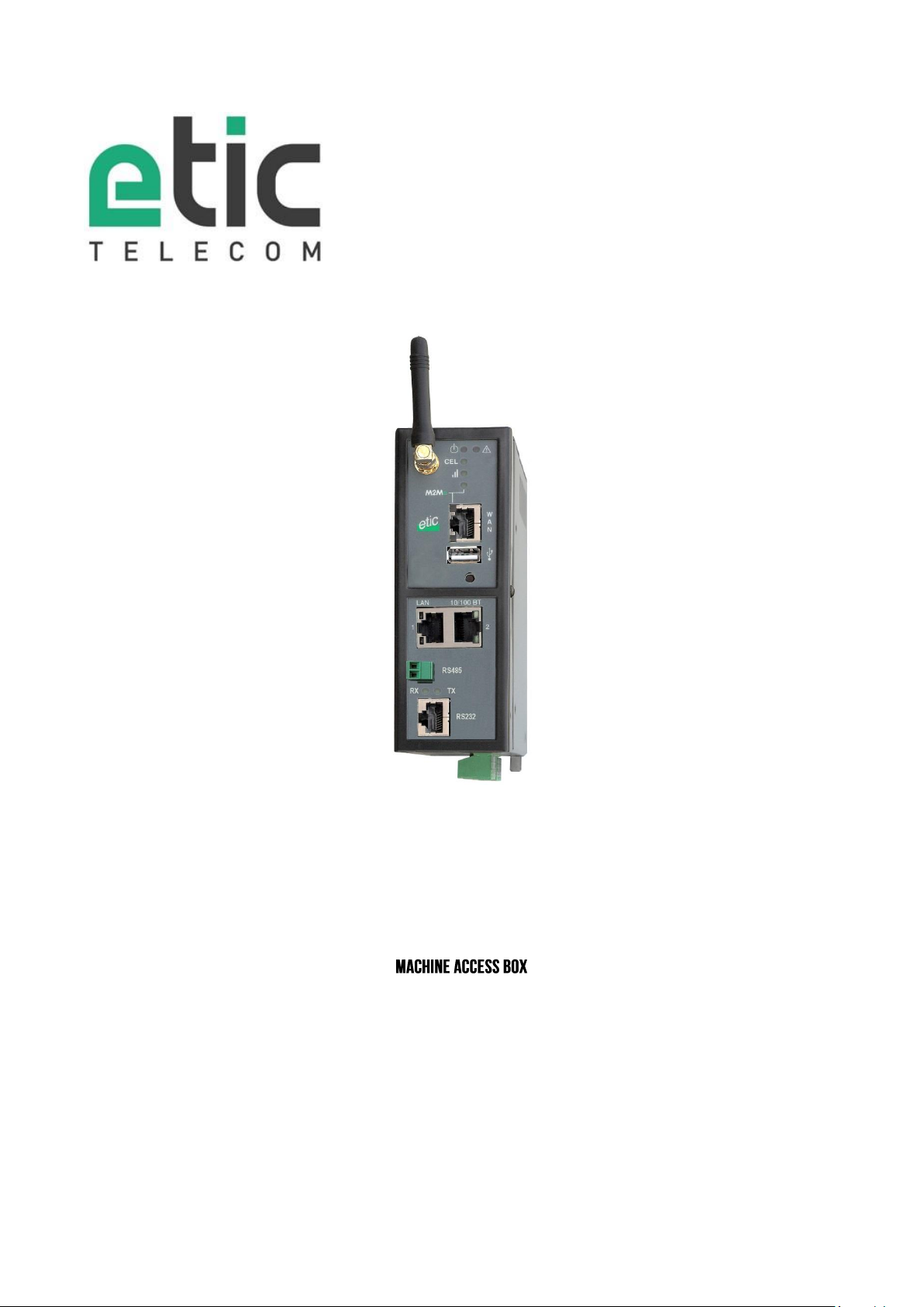
RAS-E RAS-EW
RAS-EC RAS-ECW
_________________
_________________
USER GUIDE
Machine Access Box RAS DOC_DEV_RAS_User guide_A
Page 2

CONTENT
The RAS router is manufactured by
ETIC TELECOM
13 Chemin du vieux chêne
38240 MEYLAN
FRANCE
TEL : + 33 4-76-04-20-05
FAX : + 33 4-76-04-20-01
E-mail : [email protected]
web : www.etictelecom.com
Page 2 DOC_DEV_RAS_User guide_A Machine Access Box RAS
Page 3

CONTENT
CONTENT
PRODUCT OVERVIEW ................................................................................................................. 9
CERTIFICATE OF CONFORMITY ......................................................................................... 9
PRODUCT IDENTIFICATION ............................................................................................. 10
DATA-SHEET ................................................................................................................... 14
PRODUCT OVERVIEW ...................................................................................................... 16
4.1 Main functions of the router RAS ........................................................................ 16
4.2 Router RAS organisation ................................................................................... 17
4.3 The M2Me_Connect connection .......................................................................... 18
4.4 Benefits of the M2Me_Connect service ............................................................... 19
USE CASES ..................................................................................................................... 20
5.1 Use case Nr 1 : The machine is connected to the factory network ........................ 22
5.2 Use case Nr 2 : The machine belongs to the factory network ............................... 24
5.3 Use case Nr3 : The machine is connected through a cellular network................... 25
5.4 Use case Nr4 : The machine is connected through a Wi-Fi network ...................... 26
5.5 Use case Nr 5 : Connecting the machine through the factory & a cellular ntwk ..... 27
5.6 Use case Nr 6 : Connecting the machine through the Wi-Fi & a cellular ntwk ........ 29
PRODUCT INSTALLATION ........................................................................................................ 31
PRODUCT DESCRIPTION ................................................................................................. 31
1.1 Dimensions ........................................................................................................ 31
1.2 Push-buttons ..................................................................................................... 32
1.3 Connectors ........................................................................................................ 32
1.4 RAS-E-100 router RAS ....................................................................................... 34
1.5 RAS-E or RAS-EW (Wi-Fi option) ......................................................................... 35
1.6 Cellular router RAS-EC ou RAS-ECW (Wi-Fi option) ............................................. 37
Machine Access Box RAS DOC_DEV_RAS_User guide_A Page 3
Page 4

CONTENT
… PRODUCT INSTALLATION
MOUNTING THE PRODUCT ON A DIN RAIL ....................................................................... 39
COOLING ......................................................................................................................... 39
SUPPLY VOLTAGE ........................................................................................................... 39
RS232 ............................................................................................................................. 40
RS485 CONNECTION ....................................................................................................... 40
DIGITAL INPUT AND OUTPUT .......................................................................................... 40
CONNECTING THE ROUTER TO THE CELLULAR NETWORK ............................................... 41
8.1 Controls before installing the router .................................................................... 41
8.2 Cellular antenna ................................................................................................. 41
8.3 Déport de l’antenne ......................................................... Erreur ! Signet non défini.
8.4 Cellular service subscription ............................................................................... 42
8.5 Installing the SIM card........................................................................................ 42
8.6 Controlling the conformance of the connection ................................................... 43
PREPARING THE PRODUCT SET-UP ......................................................................................... 45
FIRST SET-UP ................................................................................................................. 45
PROTECTING THE ACCESS TO THE ADMINISTRATION WEB SERVER ............................... 46
SET-UP MODIFICATIONS WITH HTTPS OR THROUGH THE WAN INTERFACE .................... 46
RECOVERING THE FACTORY LAN IP ADDRESS ................................................................ 46
RETOUR À LA CONFIGURATION USINE ............................................................................ 46
SETTING-UP THE ROUTER WITH THE WIZARD.......................................................................... 47
USE CASE 1 SET-UP ........................................................................................................ 47
USE CASE NR 2 SET-UP .................................................................................................. 52
USE CASE 3 SET-UP ........................................................................................................ 54
USE CASE 4 SET-UP ........................................................................................................ 56
USE CASE 5 SET-UP ........................................................................................................ 58
USE CASE 6 SET-UP ........................................................................................................ 61
Page 4 DOC_DEV_RAS_User guide_A Machine Access Box RAS
Page 5

CONTENT
ADVANCED SET-UP .................................................................................................................. 65
INTERNET ACCESS SET-UP ............................................................................................. 66
1.1 Overview ............................................................................................................ 66
1.2 Ethernet / WAN interface .................................................................................... 66
1.3 Cellular network interface ................................................................................... 68
1.3.1 SIM 1 or SIM 2 set-up ..................................................................................................... 68
1.3.2 Using the SIM cards 1 and 2 .......................................................................................... 69
1.3.3 Cellular connection control ............................................................................................ 70
1.4 Wi-Fi interface setup .......................................................................................... 71
LAN INTERFACE .............................................................................................................. 72
2.1 Overview ............................................................................................................ 72
2.2 Ethernet & IP menu ............................................................................................ 73
2.3 Wi-Fi access point set-up ................................................................................... 75
2.4 Device list set-up ............................................................................................... 76
2.5 DHCP server menu ............................................................................................. 77
M2ME_CONNECT CONNECTION SET-UP .......................................................................... 78
REMOTE ACCESS CONNECTION ...................................................................................... 79
4.1 Advantages of a remote access connection ........................................................ 79
4.2 Types of remote access connections .................................................................. 81
4.3 HTTPS connection and portal for smartphones, tablets or PCs ............................ 82
4.3.1 Overview .......................................................................................................................... 82
4.3.2 Set-up ............................................................................................................................... 83
4.3.3 Operation ......................................................................................................................... 83
4.4 OpenVPN remote user connection ...................................................................... 84
4.5 OpenVPN connection for smartphones ............................................................... 84
4.6 PPTP connection ................................................................................................ 85
4.7 L2TP / IPSec connection .................................................................................... 85
USER LIST ....................................................................................................................... 86
ASSIGNING RIGHTS TO REMOTE USERS ......................................................................... 88
IPSEC VPNS SET-UP ....................................................................................................... 89
7.1 Overview ............................................................................................................ 89
7.2 IPSec VPN connection set-up ............................................................................. 90
Machine Access Box RAS DOC_DEV_RAS_User guide_A Page 5
Page 6

CONTENT
… ADVANCED SET-UP
OPENVPN TYPE VPN CONNECTION ................................................................................ 95
8.1 Overview ............................................................................................................ 95
8.1.1 Set-up principles ............................................................................................................. 97
8.2 OpenVPN server set-up ...................................................................................... 98
8.3 Setting up an outgoing connection ................................................................... 100
8.4 Setting up an ingoing VPN connection .............................................................. 102
IP ROUTING ................................................................................................................... 103
9.1 Basic routing function ...................................................................................... 103
9.2 Static routes .................................................................................................... 103
9.3 RIP protocol ..................................................................................................... 105
NETWORK ADDRESS TRANSLATION (NAT) .................................................................... 106
PORT FORWARDING ...................................................................................................... 106
11.1 Overview .......................................................................................................... 106
11.2 Set-up .............................................................................................................. 107
ADVANCED NAT ............................................................................................................ 108
12.1 Overview .......................................................................................................... 108
12.2 Set-up .............................................................................................................. 109
DYNDNS OR NOIP SET-UP ............................................................................................. 110
13.1 Overview .......................................................................................................... 110
13.2 Set-up .............................................................................................................. 110
FIREWALL SET-UP ........................................................................................................ 112
14.1 Overview .......................................................................................................... 112
14.2 Main filter ........................................................................................................ 113
14.2.1 Main filter prganisation .............................................................................................. 113
Page 6 DOC_DEV_RAS_User guide_A Machine Access Box RAS
Page 7

CONTENT
… ADVANCED SET-UP
SERIAL TO IP GATEWAY CONFIGURATION ..................................................................... 115
15.1 Overview .......................................................................................................... 115
15.2 Modbus gateway .............................................................................................. 117
15.2.1 Glossary....................................................................................................................... 117
15.2.2 Selecting a Modbus client or a Modbus server gateway ........................................ 117
15.2.3 Modbus server gateway ............................................................................................. 118
15.2.4 Modbus client gateway .............................................................................................. 119
15.3 RAW TCP gateway ............................................................................................ 120
15.3.1 Raw client gateway .................................................................................................... 120
15.3.2 Raw server gateway ................................................................................................... 121
15.4 RAW UDP gateway ........................................................................................... 122
15.4.1 Overview ...................................................................................................................... 122
15.4.2 Set-up .......................................................................................................................... 122
USB GATEWAY .............................................................................................................. 123
16.1 Overview .......................................................................................................... 123
16.2 Set-up .............................................................................................................. 123
ALARM EMAIL OR A SMS .............................................................................................. 124
SNMP TRAPS ................................................................................................................ 125
ADDING A CERTIFICATE INTO THE ROUTER ................................................................... 125
MAINTENANCE ...................................................................................................................... 127
DIAGNOSTIC MENU ....................................................................................................... 127
1.1 Logs ................................................................................................................. 127
1.2 Network status ................................................................................................. 128
1.3 Serial gateways status ..................................................................................... 129
1.4 « Ping » tool ..................................................................................................... 129
1.5 « Wi-Fi » scanner tool ....................................................................................... 129
SAVING OR RESTORING A SET OF PARAMETERS .......................................................... 130
FIRMWARE UPDATE ...................................................................................................... 131
Machine Access Box RAS DOC_DEV_RAS_User guide_A Page 7
Page 8

Page 9

PRODUCT OVERVIEW
Standard
Title
EN301489-1
Electromagnetic compatibility and Radio spectrum Matters :
Part 1 : General requirements
EN301489-7
Electromagnetic compatibility and Radio spectrum Matters :
Part 7 : Specific conditions for mobile and portable radio and ancillary
equipment of digital cellular radio
EN61000-6-2
Ed. 2001
Immunity :
EN60100-4-2 Electrostatic Discharge
EN60100-4-3 Radiated Immunity
EN60100-4-4 EFT/Burst Immunity
EN60100-4-5 Surge Immunity
EN60100-4-6 Conducted Immunity
EN61000-6-4
Ed 2001
Emission :
EN55022 radiated and conducted emission
EN60950
Security
EN50385
Human exposure to radio frequency fields exposure
EN301511
Global System for mobile communication
Certificate of conformity
The manufacturer, ETIC Telecom – 13 chemin du vieux chêne – 38240 Meylan – France, Hereby declares
that the listed products
Type of device: Router RAS family described in the next pages
Conform to the Council Directive 1999/5/EC related to radio and telecommunication terminal equipments.
The harmonized standards to which the equipment complies are :
Gilles Bénas
Quality manager
5th January 2015
Machine Access Box RAS DOC_DEV_RAS_User guide_A Page 9
Page 10

PRODUCT OVERVIEW
Router RAS with Ethernet interfaces
RAS-E-
100
400
220
Ethernet interfaces to Internet
1 1 1
M2Me ready
• • •
User list
• • •
Remote users firewall
• • •
Firewall SPI
• • •
VPN IPSEC & OpenVPN
• • •
Serial gateway
(Raw TCP et UDP, Telnet, Modbus, Unitelway)
- - •
Ethernet 10 / 100 BT (LAN)
1
4
2
RS232 - -
1
RS485 - -
1
USB 1 1
1
Digital input (emails – SMS)
1 1 1
HTTPS / HTML /SSH configuration
• • •
Advanced IP router functions
NAT, port forwarding, SNMP, DHCP
• • •
Product identification
Page 10 DOC_DEV_RAS_User guide_A Machine Access Box RAS
Page 11

PRODUCT OVERVIEW
Router RAS with Ethernet & Wi-Fi interfaces
RAS-EW-
400
220
Ethernet interfaces to Internet
1
1
Wi-Fi interface (Access point & client)
•
•
M2Me ready
•
•
User list
•
•
Remote users firewall
•
•
Firewall SPI
•
•
VPN IPSEC & OpenVPN
•
•
Serial gateway
(Raw TCP et UDP, Telnet, Modbus, Unitelway)
-
•
Ethernet 10 / 100 BT (LAN)
4
2
RS232 - 1
RS485
-
1
USB
1
1
Digital input (emails – SMS)
1
1
HTTPS / HTML /SSH configuration
•
•
Advanced IP router functions
NAT, port forwarding, SNMP, DHCP
•
•
Machine Access Box RAS DOC_DEV_RAS_User guide_A Page 11
Page 12

PRODUCT OVERVIEW
Router RAS with cellular & Ethernet interfaces
RAS-EC-
400
220
Cellular ntwk router LTE 4G - UMTS 3G -GPRS-EDGE
UMTS 3G -GPRS-EDGE : XY = HG
LTE 4G - UMTS 3G -GPRS-EDGE XY =LE
•
•
Ethernet interfaces to Internet
1
1
M2Me ready
•
•
User list
•
•
Remote users firewall
•
•
Firewall SPI
•
•
VPN IPSEC & OpenVPN
•
•
Serial gateway
(Raw TCP et UDP, Telnet, Modbus, Unitelway)
-
•
Ethernet 10 / 100 BT (LAN)
4
2
RS232 - 1
RS485
-
1
USB
1
1
Digital input (emails – SMS)
1
1
HTTPS / HTML /SSH configuration
•
•
Advanced IP router functions
NAT, port forwarding, SNMP, DHCP
•
•
Page 12 DOC_DEV_RAS_User guide_A Machine Access Box RAS
Page 13

PRODUCT OVERVIEW
Router RAS with cellular, Wi-Fi & Ethernet interfaces
RAS-ECW-
400
220
Cellular ntwk router LTE 4G - UMTS 3G -GPRS-EDGE
UMTS 3G -GPRS-EDGE : XY = HG
LTE 4G - UMTS 3G -GPRS-EDGE XY =LE
•
•
Ethernet interfaces to Internet
1
1
Wi-Fi interface (Access point & client)
•
•
M2Me ready
•
•
User list
•
•
Remote users firewall
•
•
Firewall SPI
•
•
VPN IPSEC & OpenVPN
•
•
Serial gateway
(Raw TCP et UDP, Telnet, Modbus, Unitelway)
-
•
Ethernet 10 / 100 BT (LAN)
4
2
RS232 - 1
RS485
-
1
USB
1
1
Digital input (emails – SMS)
1
1
HTTPS / HTML /SSH configuration
•
•
Advanced IP router functions
NAT, port forwarding, SNMP, DHCP
•
•
Machine Access Box RAS DOC_DEV_RAS_User guide_A Page 13
Page 14
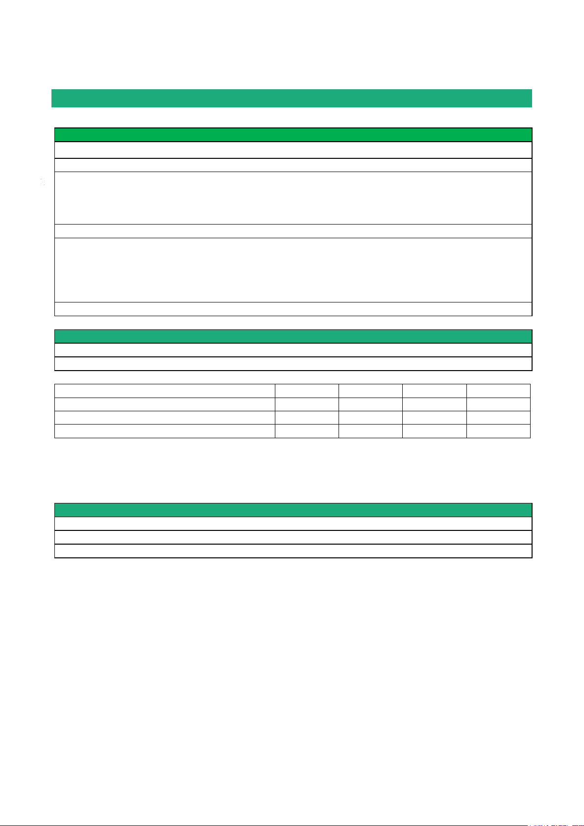
PRODUCT OVERVIEW
General characteristics
Dimensions
137 x 48 x 116 mm (h, l, p)
Electrical safety
EN 60950- UL 1950
EMC
ESD : EN61000-4-2 : Discharge 6 KV
RF field : EN61000-4-3 : 10V/m < 2 GHz
Fast transient : EN61000-4-4
Surge voltage : EN61000-4-5 : 4KV line / earth
RoHS
2002/95/CE (RoHS)
Supply voltage
RAS-3G-1220 : 10 to 30 VDC - 125 mA / 24 VDC
RAS-3G-1201 : 10 to 60 VDC - 125 mA / 24 VDC
RAS-3G-1230 : 10 to 60 VDC - 125 mA / 24 VDC
RAS-3G-1400 : 10 to 60 VDC - 210mA / 24 VDC
Operating T°
-20°C / + 60°C Humidity 5 – 95 %
Cellular network
Type
4G / 3G+ / GPRS-EDGE
RF connector
SMA female
Models
LE
LS
LA
HG
LTE 4G
Europe
USA
Asia
-
UMTS 3G+
Yes (*1)
Yes (*1)
Yes (*1)
Yes (*2)
GPRS-EDGE
Yes (*3)
Yes (*3)
Yes (*3)
Yes (*3)
Wi-Fi
Type
2.4 et 5 GHz
RF connector
R-SMA female
Wi-Fi transmission
802.11 a/b/g/n
Data-sheet
(*1) 850 / 900 / 1900 / 2100 MHz
(*2) 850 / 900 / 1700 / 1900 / 2100 MHz
(*3) 850 / 900 / 1800 / 1900 MHz
Page 14 DOC_DEV_RAS_User guide_A Machine Access Box RAS
Page 15
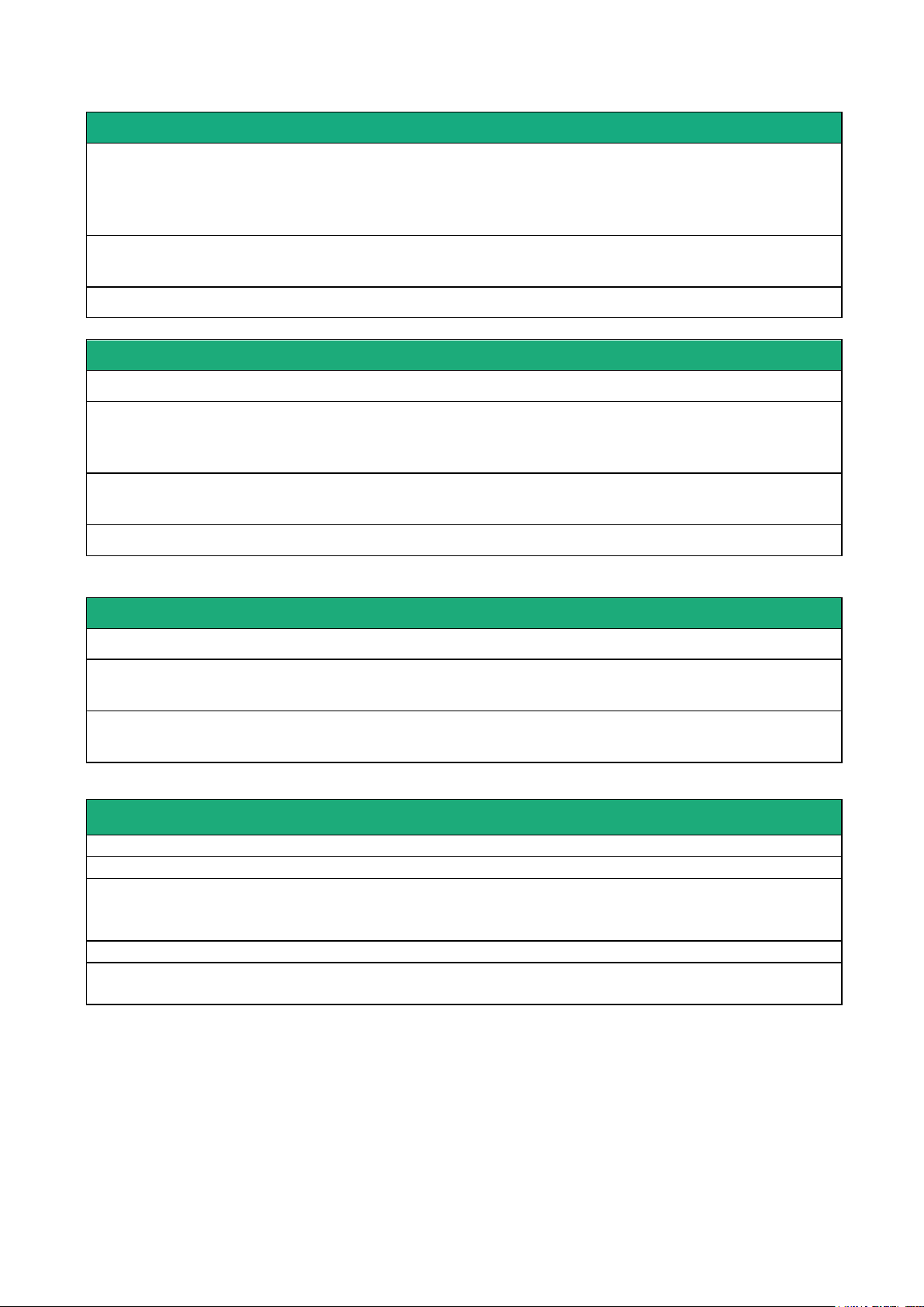
PRODUCT OVERVIEW
Security
VPN
Client or server IPSEC or TLS/SSL
Encryption AES256 3DES
Certificate X509 or preshared key
25 VPNs maximum of the same type (TLS or IPSec)
Firewall
Stateful packet inspection (50 rules)
Source & destination IP address & port number filter
Logs
Date and time stamped logs
Remote access server (RAS)
User list
25 users
Connection
VPN PPTP / L2TP-IPSec / TLS Open VPN
Login & password
Certificate X509
M2Me (*)
VPN Compliant with the M2Me_Secure VPN client
Compliant with the M2Me_Connect mediation service
Alarms
3 inputs : emails
Asynchronous serial interface
Data rate
1200 to 115200 kb/s parity N / E / O
Gateway
Raw client & server - Modbus master & slave
Multicast - Telnet - Unitelway
USB
1 USB host port
PPP client over the usb interface
IP router
Ethernet
10/100 BT – 2 or 4 switched ports
IP router
Remote connections - static routes – RIP V2
IP address
translation
Source IP @ translation (NAT)
Destination IP @ translation (DNAT)
Port translation (Port forwarding)
DNS
Domain name
IP address
assignment
Fixed IP @ or DHCP client or DHCP server
Machine Access Box RAS DOC_DEV_RAS_User guide_A Page 15
Page 16
PRODUCT OVERVIEW
Product overview
4.1 Main functions of the router RAS
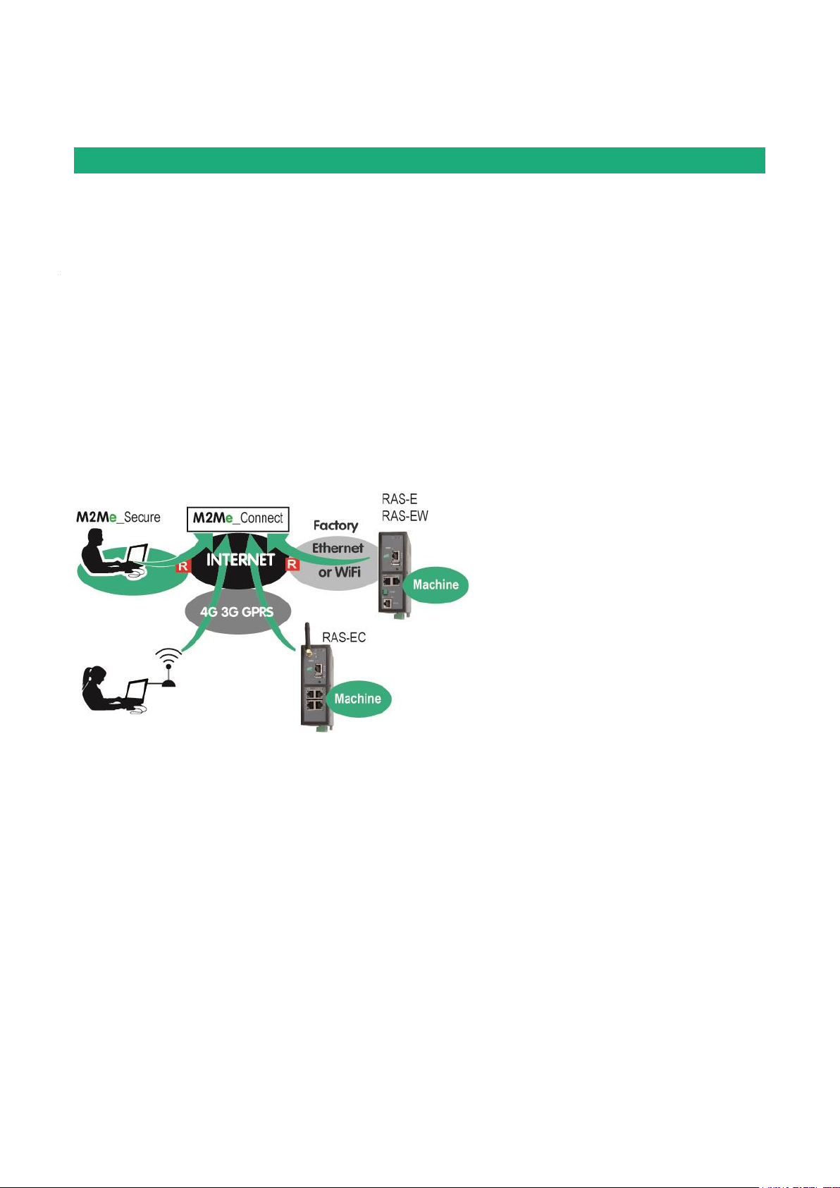
Remote maintenance of machines using the M2Me_Connect service
The RAS family allows to connect easily and safely a machine to a remote PC, through the M2Me_Connect
Internet cloud service, for operation like remote maintenance.
When the remote PC is connected, the remote user can exchange any kind of data with each device of the
machine network as if his PC was directly connected to the machine network.
Ethernet or serial devices
The machine can consist of one or several devices connected through an Ethernet machine network or
connected through a serial RS232-RS485 interface.
The router RAS can be connected to the Internet through a cellular network, a Wi-Fi network or a factory
network
An Up-to-date IP router for particular situations
When using the Expert mode set-up, the router RAS becomes a powerful IP router-RAS-firewall for industrial
IP networks applications.
Page 16 DOC_DEV_RAS_User guide_A Machine Access Box RAS
Page 17

PRODUCT OVERVIEW
WAN interfaces
RAS-E
RAS-EW
RAS-EC
RAS-ECW
Ethernet
Wi-Fi
Cellular
4.2 Router RAS organisation
The router RAS connects to the devices network (called machine) and on the other hand to the Internet
The router RAS provides two IP interfaces : The WAN interface to reach the Internet and the LAN interface to
connect the machine.
WAN interface :
Depending on the model, the router RAS provides the following interfaces to reach the Internet :
The network connected to the WAN interface is called the WAN network or factory network.
LAN interface :
Depending on the model, the router RAS provides 1 to 4 switched Ethernet ports to connect the devices of
the machine.
That network is called the machine network.
1 serial RS232 and 1 serial RS485 interfaces are provided optionally.
Firewall
The firewall filters data between the WAN interface or any VPN interface on one hand, and the LAN interface
on the other hand.
The firewall filters source and destination IP addresses, but also remote users according to their identity.
Machine Access Box RAS DOC_DEV_RAS_User guide_A Page 17
Page 18

PRODUCT OVERVIEW
4.3 The M2Me_Connect connection
Connecting a remote PC to a machine in any situation
M2Me Connect service is an ideal solution when a « machine », made of a set of devices connected to the
same LAN, is located in a private network (such as a Factory network).
Let’s take the example of a « machine » made of a set of connected devices and connected to the Factory
Network via a RAS-E.
Assuming that an expert is willing to remotely have access to the machine for breakdown diagnosis,
technical data acquisition, Web page display, file or program refreshment, M2Me Connect service enables
the remote operator to have access to the machine even if the machine does not have any public IP address.
Operation
When it is powered on or if the digital input is enabled, the router RAS settles a secured VPN connection
onto the M2Me Connect cloud service.
The remote PC is authenticated by the M2Me Cloud service.
Assuming that the router RAS provides two WAN connections (Cellular and Ethernet as an example), it
settles the best connection (Through the Ethernet network if possible) to the M2Me cloud service.
On the other hand, the remote user launches its M2Me secure software and settles a secured VPN
connection to the M2Me Cloud.
The directory offered by M2Me_Secure is helping the user to point the remote machine onto which he wants
to be connected.
The router RAS verifies thenafter that the remote user is allowed to be connected by checking its login &
password and as an option the certificate of the remote PC.
The router RAS grants to the remote user access rights according to its identity.
In order to warrant the level of security requested by industrial application, connection from PC to RAS is
fully encrypted and cannot be recovered even in case of intrusion onto the M2Me Connect cloud service.
Page 18 DOC_DEV_RAS_User guide_A Machine Access Box RAS
Page 19

PRODUCT OVERVIEW
4.4 Benefits of the M2Me_Connect service
Outgoing connection
M2Me connection onto the Internet is powered from the RAS. This non intrusive solution is better admitted
than an ingoing connection from the Internet onto the Machine.
Private & dynamic IP address
The machine connected into a factory network or connected to the Internet via a cellular network does not
have a public IP address. M2Me solution does not require a public IP address to settle a connection onto the
machine.
Access to each device of the machine
M2Me teleport your PC onto the machine network enabling you to have access to each device of the
machine as if you were in front of the machine.
Machine with Ethernet or serial connection
The family of RAS enables you to set up a connection to any type of PLC offering an Ethernet or a serial
connectivity.
Simple configuration of router RAS
Html configuration Server is delivered with a Wizard which gives an intuitive way of configuring the device.
Simple Operation
M2Me Secure software offers e set of directories for the remote machines. One click is enough to be
connected.
Security of customer network (Factory or WAN network)
Router RAS enables the remote operator to have access only to the machine network protecting the factory
network from any intrusion.
Machine & Device Access protection
A remote user can access to the machine if and only if its identification (login & password) has been
preregistered in the RAS router
An extra security option is offered. RAS can also demand the certificate installed in the PC of the remote
user.
The RAS can also give restricted access to the machine network giving access only to certain devices of the
machine and not to all.
Internet & Security
The flow of information passing through the M2Me connection is fully encrypted and requires authentication
to the M2Me server of both the PC of the remote user and the RAS router. A third party cannot consequently
have access to the machine preserving the integrity of the industrial process to be remote maintained.
Machine Access Box RAS DOC_DEV_RAS_User guide_A Page 19
Page 20

PRODUCT OVERVIEW
Use cases
There are different ways to connect the router RAS to the Internet and to the machine depending on the
situation which is encountered and also on the router RAS model.
We describe hereafter six typical situations.
Page 20 DOC_DEV_RAS_User guide_A Machine Access Box RAS
Page 21
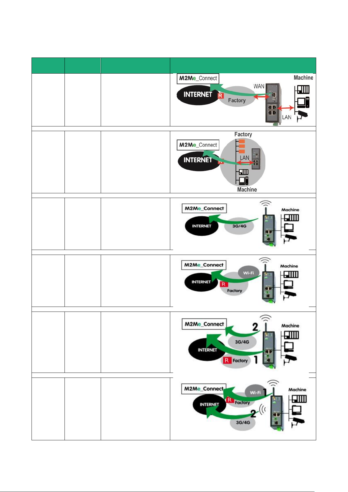
PRODUCT OVERVIEW
Use case
Internet
access
Internet
1
RAS-E
RAS-EW
RAS-EC
RAS-ECW
Factory
network
The machine is
connected to the
factory network
through the router RAS.
2
RAS-E
RAS-EW
RAS-EC
RAS-ECW
Factory
network
The machine belongs to
the factory network.
3
RAS-EC
RAS-ECW
Cellular
network
The machine is
connected to the
Internet through a
cellular network.
4
RAS-EW
RAS-ECW
Wi-Fi
The machine is
connected to the
Internet through a Wi-Fi
network.
5
RAS-EC
RAS-ECW
Factory
network
+ cellular
network
The machine is
connected to the
Internet through the
factory network and, if
it is not available,
through a cellular
network.
6
RAS-ECW
Wi-Fi
+ cellular
network
The machine is
connected to the
Internet through the WiFi network and, if it is
not available, through a
cellular network.
Machine Access Box RAS DOC_DEV_RAS_User guide_A Page 21
Page 22
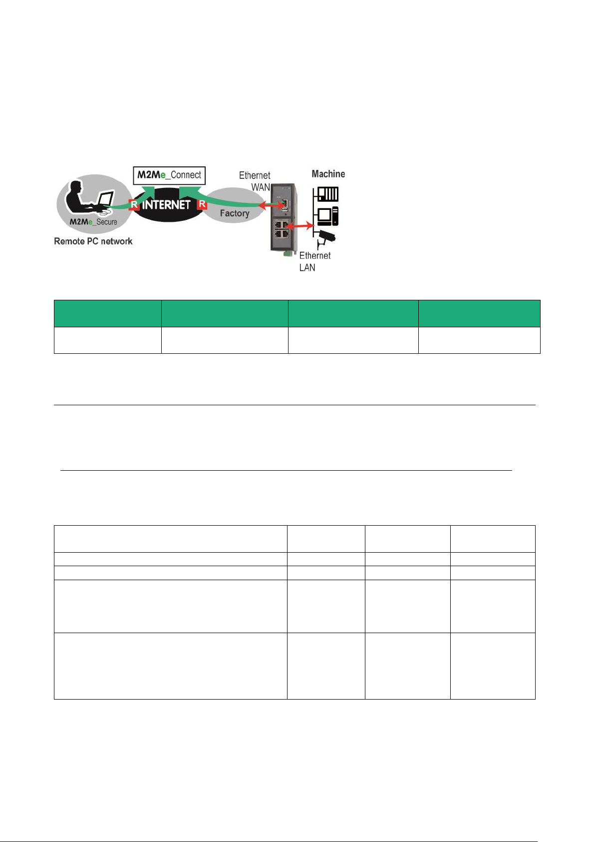
PRODUCT OVERVIEW
Models
Way to the Internet
Router RAS interface to
the Internet
Machine interface
All models
Factory network
Ethernet WAN
Ethernet LAN 1 to 4
Serial interface
Examples :
Remote PC
network
Factory
network
Machine
network
OK
192.168.10.0
192.168.1.0
192.168.12.0
OK
192.168.10.0
192.168.10.0
192.168.12.0
The IP domain of the machine ntwk and of the
factory ntwk are the same.
The machine IP domain must be modified or the
RAS must be used according to the use case 2
192.168.10.0
192.168.1.0
192.168.1.0
The IP domain of the machine ntwk and of the
remote PC ntwk are the same.
The machine IP domain must be modified or the
address translation option must be selected (see
the wizard menu).
192.168.10.0
192.168.1.0
192.168.10.0
5.1 Use case 1 : The machine is connected to the factory network
Description
The machine is separated from the factory network by the router RAS. The Internet is reached through the
factory network.
Machine IP address
Rule 1 : The IP domain of the machine network and the IP domain of the factory network must be different.
If both domains are identical, the IP domain of the machine must be modified or he RAS must be used
according to the Use case Nr 2 described below.
Rule 2 : The IP domain of the machine network and the IP domain of the remote PC must be different.
If both IP domains are identical, the IP domain of the machine must be modified or the machine network
translation option must be selected.
Page 22 DOC_DEV_RAS_User guide_A Machine Access Box RAS
Page 23

PRODUCT OVERVIEW
Available functions
Connecting the remote PC to each device of the machine network through M2Me
Individual rights for each the remote user
Communication initiated by devices belonging to the machine network towards
devices belonging to the factory network
Communication initiated by devices belonging to the factory network towards
devices belonging to the machine network
Enabled by creating
a firewall rule
Setting an additional VPN towards a server
Sending an email (all models) or a SMS (RAS-EC or RAS-ECW)
Security
The factory network and the machine network are separated by the router RAS. This is why the firewall can
operate to filter exchanges between these two networks; the machine is protected from unexpected
exchanges initiated by any device connected to the factory network. The firewall can be configured to
authorise particular exchanges.
Machine Access Box RAS DOC_DEV_RAS_User guide_A Page 23
Page 24
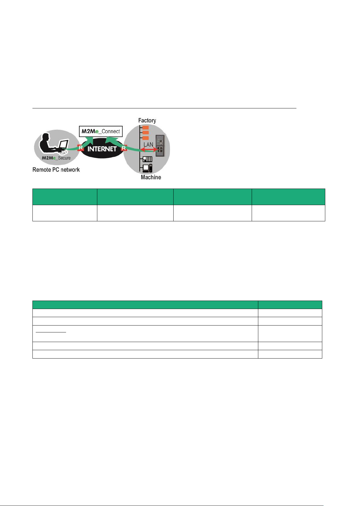
PRODUCT OVERVIEW
Models
Way to the Internet
Router RAS interface to
the Internet
Machine interface
All models
Factory network
Ethernet LAN ports
Ethernet LAN 1 to 4
Serial interface
Available functions
Connecting the remote PC to each device of the machine network through M2Me
Individual rights for each the remote user
Not filtered communication between the devices of the machine and devices of
the factory network
Setting an additional VPN towards a server
Sending an email (all models) or a SMS (RAS-EC or RAS-ECW)
5.2 Use case 2 : The machine belongs to the factory network
Description
The devices of the machine belong to the factory network.
The Internet is reached through the existing access.
In that case, the router RAS has to be connected to the factory network with its LAN Ethernet port.
Machine IP addresses
Rule : The IP domain of the machine network and the IP domain of the remote PC network must be
different.
If both IP domains are identical, it is possible to select the machine network translation option (see the
wizard configuration menu for detailed information); the IP domain of the devices of the machine is virtually
modified for the remote PC.
Security
The remote users can access only to the authorized devices of the unique machine and factory network.
But, because all the devices are connected to the same network, exchanges cannot be filtered on the local
network.
Page 24 DOC_DEV_RAS_User guide_A Machine Access Box RAS
Page 25
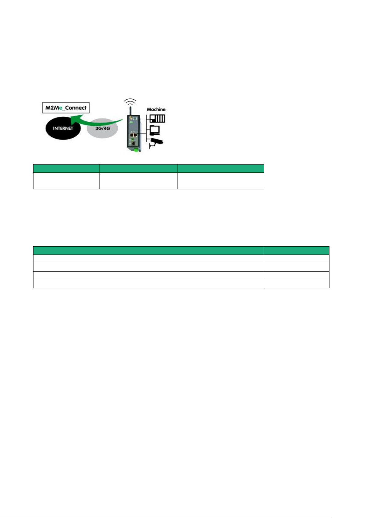
PRODUCT OVERVIEW
Models
Way to the Internet
Machine interface
RAS-EC
RAS-ECW
Cellular network
Ethernet LAN 1 to 4
Serial interface
Available functions
Connecting the remote PC to each device of the machine network through M2Me
Individual rights for each the remote user
Setting an additional VPN towards a server
Sending an email (all models) or a SMS (RAS-EC or RAS-ECW)
5.3 Use case 3 : The machine is connected through a cellular network
Description
The Internet is reached through a cellular network.
Machine IP address
Rule : The IP domain of the machine network and the IP domain of the remote PC must be different.
If both IP domains are identical, the IP domain of the machine must be modified or the machine network
translation option must be selected (see the wizard configuration menu for detailed information).
Security
The remote user can only communicate with the authorised devices.
The availability and the quality of a cellular network is sometimes lower than a company network internet
access. It is important to check this situation will not provoke any kind of danger for people on the machine
site or of any other kind.
Machine Access Box RAS DOC_DEV_RAS_User guide_A Page 25
Page 26
PRODUCT OVERVIEW
Models
Way to the Internet
Machine interface
RAS-EC
RAS-ECW
Cellular network
Ethernet LAN 1 to 4
Serial interface
Available functions
Connecting the remote PC to each device of the machine network through M2Me
Individual rights for each the remote user
Setting an additional VPN towards a server
Sending an email (RAS-EW) or a SMS (RAS-ECW)
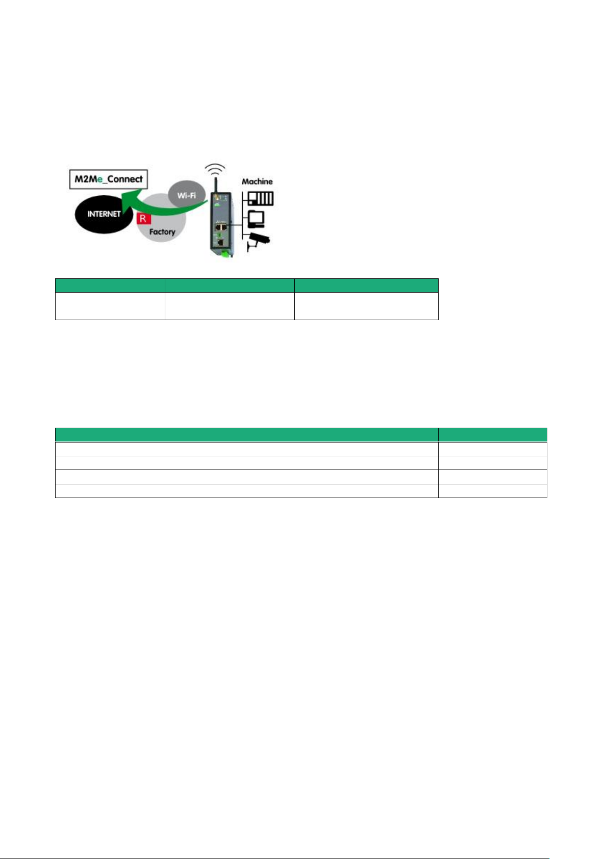
5.4 Use case 4 : The machine is connected through a Wi-Fi network
Description
The Internet is reached through a Wi-Fi network.
Machine IP address
Rule : The IP domain of the machine network and the IP domain of the remote PC must be different.
If both IP domains are identical, the IP domain of the machine must be modified or the machine network
translation option must be selected (see the wizard configuration menu for detailed information).
Security
The remote user can only communicate with the authorized devices.
The availability and the quality of a Wi-Fi network is sometimes lower than a company network. It is
important to check this situation will not provoke any kind of danger.
Page 26 DOC_DEV_RAS_User guide_A Machine Access Box RAS
Page 27
PRODUCT OVERVIEW
Models
Way to the Internet
Internet interface
Machine interface
RAS-EC
RAS-ECW
Factory network
Ethernet WAN
Ethernet LAN 1 to 4
Serial interface
Cellular network
Cellular antenna
Examples :
Remote PC
network
Factory
network
Machine
network
OK
192.168.10.0
192.168.1.0
192.168.12.0
OK
192.168.10.0
192.168.10.0
192.168.12.0
The IP domain of the machine ntwk and of the
factory ntwk are the same.
The machine IP domain must be modified or the
RAS must be used according to the use case 2
192.168.10.0
192.168.1.0
192.168.1.0
The IP domain of the machine ntwk and of the
remote PC ntwk are the same.
The machine IP domain must be modified or the
address translation option must be selected (see
the wizard menu).
192.168.10.0
192.168.1.0
192.168.10.0
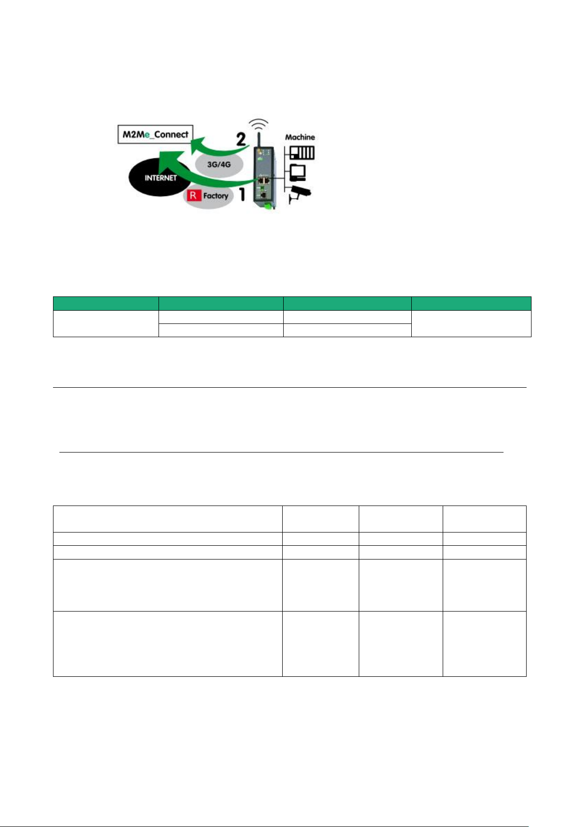
5.5 Use case 5 : The machine is connected through the factory & a cellular ntwk
Description
Reaching the Internet through the factory network may not be immediately authorized or available at the
moment of the machine installation; it is the reason why, the router RAS (RAS-EC or RAS-ECW) is able to
select the available way to the Internet; the factory network access to the Internet is selected as a priority
and the cellular network is used as a backup solution. The router RAS switches automatically between that
both ways.
Machine IP address
Rule 1 : The IP domain of the machine network and the IP domain of the factory network must be different.
If both domains are identical, the IP domain of the machine must be modified or he RAS must be used
according to the use case Nr 2 described above.
Rule 2 : The IP domain of the machine network and the IP domain of the remote PC must be different.
If both IP domains are identical, the IP domain of the machine must be modified or the machine network
translation option must be selected.
Machine Access Box RAS DOC_DEV_RAS_User guide_A Page 27
Page 28

PRODUCT OVERVIEW
Available functions
Connecting the remote PC to each device of the machine network through M2Me
Individual rights for each the remote user
Communication initiated by devices belonging to the machine network towards
devices belonging to the factory network
Communication initiated by devices belonging to the factory network towards
devices belonging to the machine network
Enabled by creating
a firewall rule
Setting an additional VPN towards a server
Sending an email or a SMS
Security
The remote user can only communicate with the authorized devices.
The availability and the quality of a cellular network is sometimes lower than a company network. It is
important to check this situation will not provoke any kind of danger.
Page 28 DOC_DEV_RAS_User guide_A Machine Access Box RAS
Page 29
PRODUCT OVERVIEW
Models
Way to the Internet
Internet interface
Machine interface
RAS-EC
RAS-ECW
Wi-Fi network
Ethernet WAN
Ethernet LAN 1 to 4
Serial interface
Cellular network
Cellular antenna
Examples :
Remote PC
network
Factory
network
Machine
network
OK
192.168.10.0
192.168.1.0
192.168.12.0
OK
192.168.10.0
192.168.10.0
192.168.12.0
The IP domain of the machine ntwk and of the
factory ntwk are the same.
The machine IP domain must be modified or the
RAS must be used according to the use case 2
192.168.10.0
192.168.1.0
192.168.1.0
The IP domain of the machine ntwk and of the
remote PC ntwk are the same.
The machine IP domain must be modified or the
address translation option must be selected (see
the wizard menu).
192.168.10.0
192.168.1.0
192.168.10.0
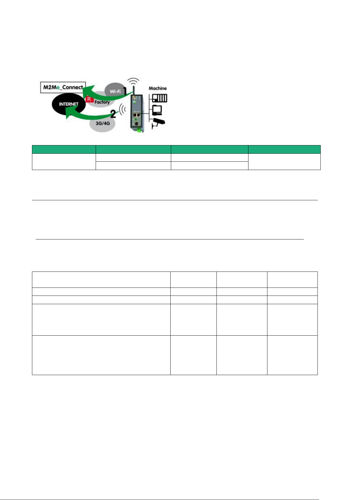
5.6 Use case 6 : The machine is connected through a Wi-Fi & a cellular ntwk
Description
Machine IP address
Rule 1 : The IP domain of the machine network and the IP domain of the factory network must be different.
If both domains are identical, the IP domain of the machine must be modified or he RAS must be used
according to the use case Nr 2 described below.
Rule 2 : The IP domain of the machine network and the IP domain of the remote PC must be different.
If both IP domains are identical, the IP domain of the machine must be modified or the machine network
translation option must be selected.
Machine Access Box RAS DOC_DEV_RAS_User guide_A Page 29
Page 30

PRODUCT OVERVIEW
Available functions
Connecting the remote PC to each device of the machine network through M2Me
Individual rights for each the remote user
Communication initiated by devices belonging to the machine network towards
devices belonging to the factory network
Communication initiated by devices belonging to the factory network towards
devices belonging to the machine network
Enabled by creating
a firewall rule
Setting an additional VPN towards a server
Sending an email or a SMS
Security
The remote user can only communicate with the authorized devices.
The availability and the quality of a cellular network is sometimes lower than a company network. It is
important to check this situation will not provoke any kind of danger.
Page 30 DOC_DEV_RAS_User guide_A Machine Access Box RAS
Page 31
PRODUCT INSTALLATION
Product description
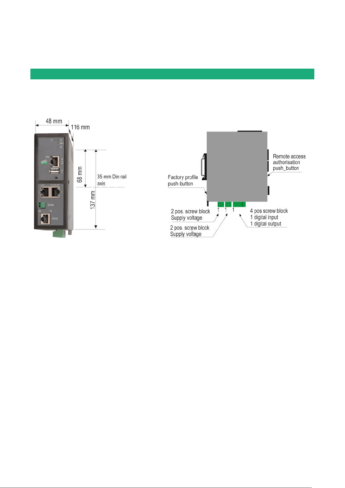
1.1 Dimensions
Machine Access Box RAS DOC_DEV_RAS_User guide_A Page 31
Page 32
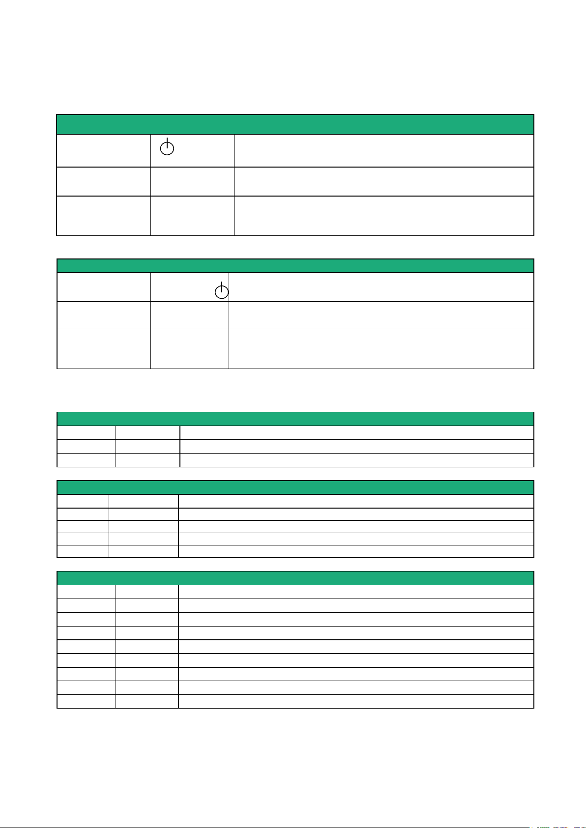
INSTALLATION
Rear panel push-button
Pressing the rear
panel PB
led
Function
During operation
Flashing red
The default IP address 192.168.0.128 is selected
The current configuration remains active
During power-up
Flashing red
The factory configuration and the default IP address
192.168.0.128 are selected.
The current configuration is deleted.
Front panel push-button
Pressing the front
panel PB
led
Function
During 5 seconds
3 flashes
The hotline of ETICTELECOM is authorised to connect remotely to
the router administration server within a 1 hour delay.
During 10 seconds
5 flashes
A remote user is authorised to connect remotely to the router
administration server within a 10 mn delay without entering the
login r password
Supply voltage connector (C1 or C2)
Position
Signal
Fonction
1
Power 1 +
Supply voltage
2
Power 1 -
0V
Digital inputs & outputs (C3)
Position
Signal
Fonction
1
0V
TOR 0V 2 In
TOR+ Digital input
3
F +
Dgital output +
4
F -
Digital output -
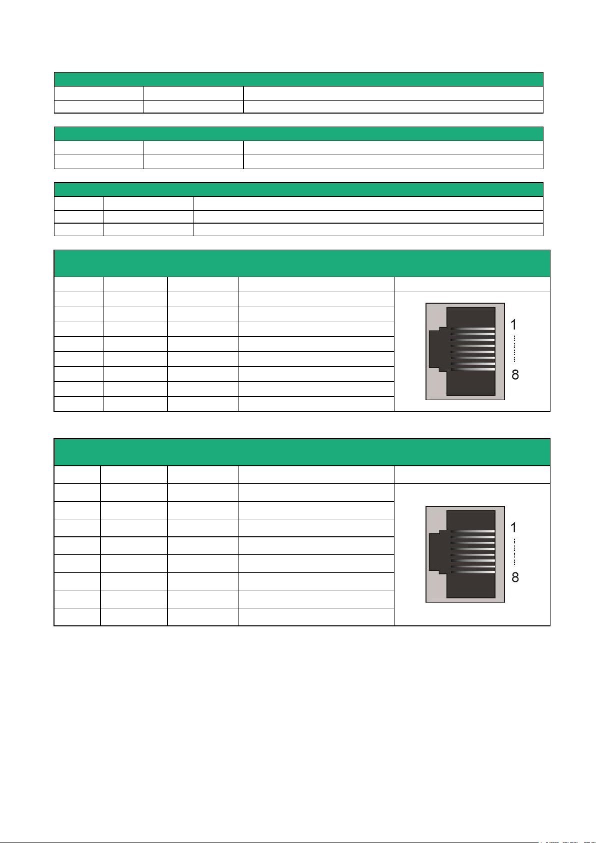
RJ45 Ethernet)
Position
Name
Description
1
Tx +
Emission polarity +
2
Tx -
Emission polarity -
3
Rx +
Reception polarity +
4
N.C - 5
N.C - 6
Rx -
Reception polarity -
7
N.C.
-
8
N.C.
-
1.2 Push-buttons
1.3 Connectors
Page 32 DOC_DEV_RAS_User guide_A Machine Access Box RAS
Page 33
INSTALLATION
Wi-Fi Antenna connector
Network
Type
Observation
Wi-Fi
RP-SMA female
Celular Antenna connector
Network
Type
Observation
Cellular
SMA female
2 positions RS485 screw block (C10)
Position
Signal
Fonction
1
A
RS485 polarity A
2
B
RS485 polarity B
RJ45 RS232
DCE interface
Pos.
Signal Function
RJ45
1
DTR - 108
OUT
Data terminal ready
2
TD - 103
OUT
Data Emission
3
RD - 104
IN
Data Reception
4
DSR - 107
IN
Data set ready
5
SG - 102
-
Ground
6
Inutilisé
OUT
-
7
CTS - 106
IN
Clear to send
8
RTS - 105
OUT
Request to send
RJ45 RS232
DTE interface
Pos.
Signal Fonction
RJ45
1
CD - 109
OUT
Carrier detect
2
RD - 104
OUT
Data Reception
3
TD - 103
IN
Data Emission
4
DTR - 108
IN
Data terminal ready
5
SG - 102
-
Ground
6
DSR - 107
OUT
Data set ready
7
RTS - 105
IN
Request to send
8
CTS - 106
OUT
Clear to send
Out = Signal provided by the router.
Out = Signal provided by the router.
Machine Access Box RAS DOC_DEV_RAS_User guide_A Page 33
Page 34
INSTALLATION
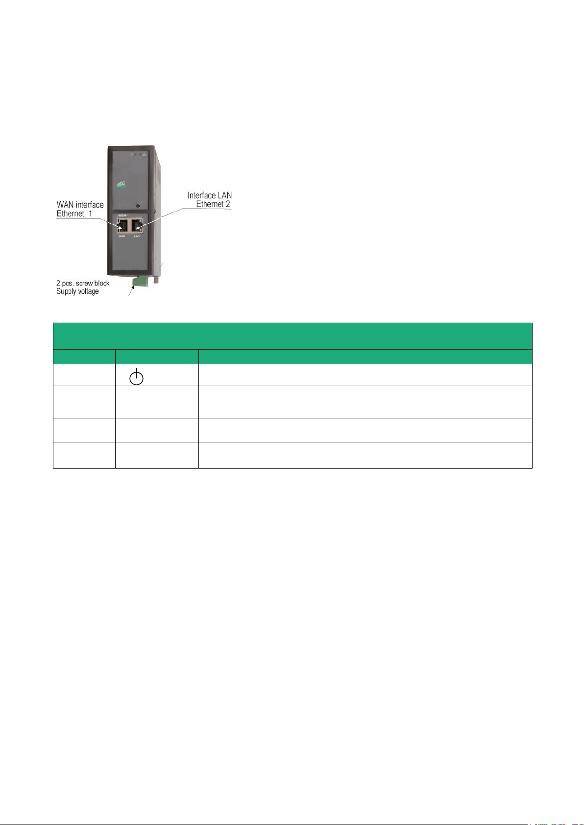
LED INDICATORS
RAS-E-100 et RAS-EW-100
Designation
Function
Operation
Green The unit is ready
Flashing red Hardware default
Ethernet
WAN
M2Me
Off M2Me_Connect not selected
Flashing M2Me_Connect connection in progress
Green The unit is connected to the M2Me_Connect service
Ethernet
WAN
Off Ethernet interface not connected
Green Ethernet interface connected
Ethernet LAN
Off Ethernet interface not connected
Green Ethernet interface connected
.
1.4 RAS-E-100 router RAS
Page 34 DOC_DEV_RAS_User guide_A Machine Access Box RAS
Page 35
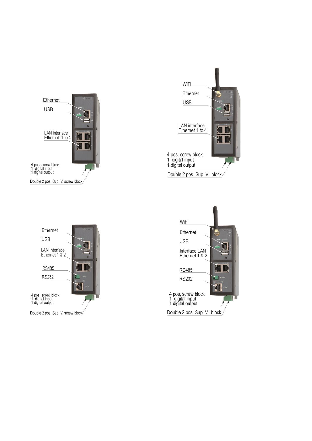
RAS-E-400
RAS-EW-400
RAS-E-220
RAS-EW-220
1.5 RAS-E or RAS-EW (Wi-Fi option)
INSTALLATION
Machine Access Box RAS DOC_DEV_RAS_User guide_A Page 35
Page 36
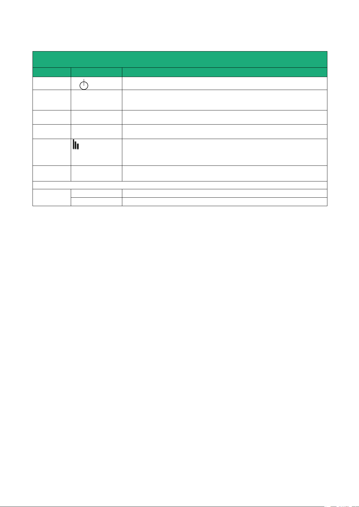
INSTALLATION
LED INDICATORS
RAS-E-XYZ et RAS-EW-XYZ
Designation
Function
Operation
Green The unit is ready
Flashing red Hardware default or unit start step
Ethernet
WAN
M2Me
Off M2Me_Connect not selected
Flashing M2Me_Connect connection in progress
Green The unit is connected to the M2Me_Connect service
Ethernet
WAN
Off Ethernet interface not connected
Green Ethernet interface connected
Wi-Fi
connection
Wi-Fi
Off Wi-Fi Interface not enabled
Green Wi-Fi Interface enabled
Wi-Fi
Signal
quality
Wi-Fi
Off Wi-Fi not enabled or enabled as an access point
1 flash Faint not sufficient signal
2 flashes Sufficient signal
3 flashes Strong signal
Ethernet LAN
1 to 4
Off Ethernet interface not connected
Green Ethernet interface connected
RAS-E-220 RAS—EW-220
RS232
RS485
Rx
Characters received from the serial interface (to the router RAS)
Tx
Characters transmitted to the serial interface (from the router RAS)
Page 36 DOC_DEV_RAS_User guide_A Machine Access Box RAS
Page 37
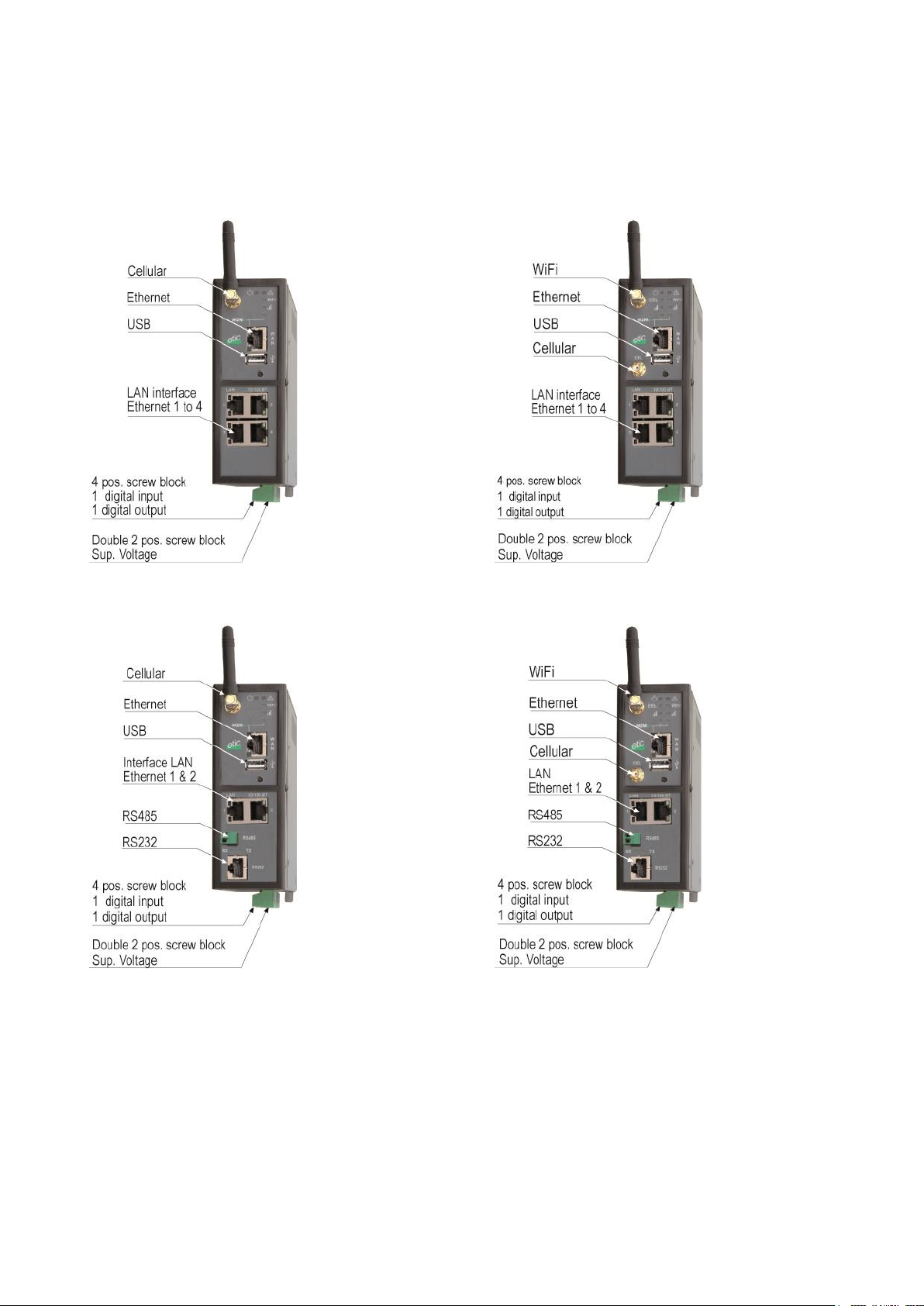
RAS-EC-400
RAS-ECW-400
RAS-EC-220
RAS-ECW220
1.6 Cellular router RAS-EC ou RAS-ECW (Wi-Fi option)
INSTALLATION
Machine Access Box RAS DOC_DEV_RAS_User guide_A Page 37
Page 38
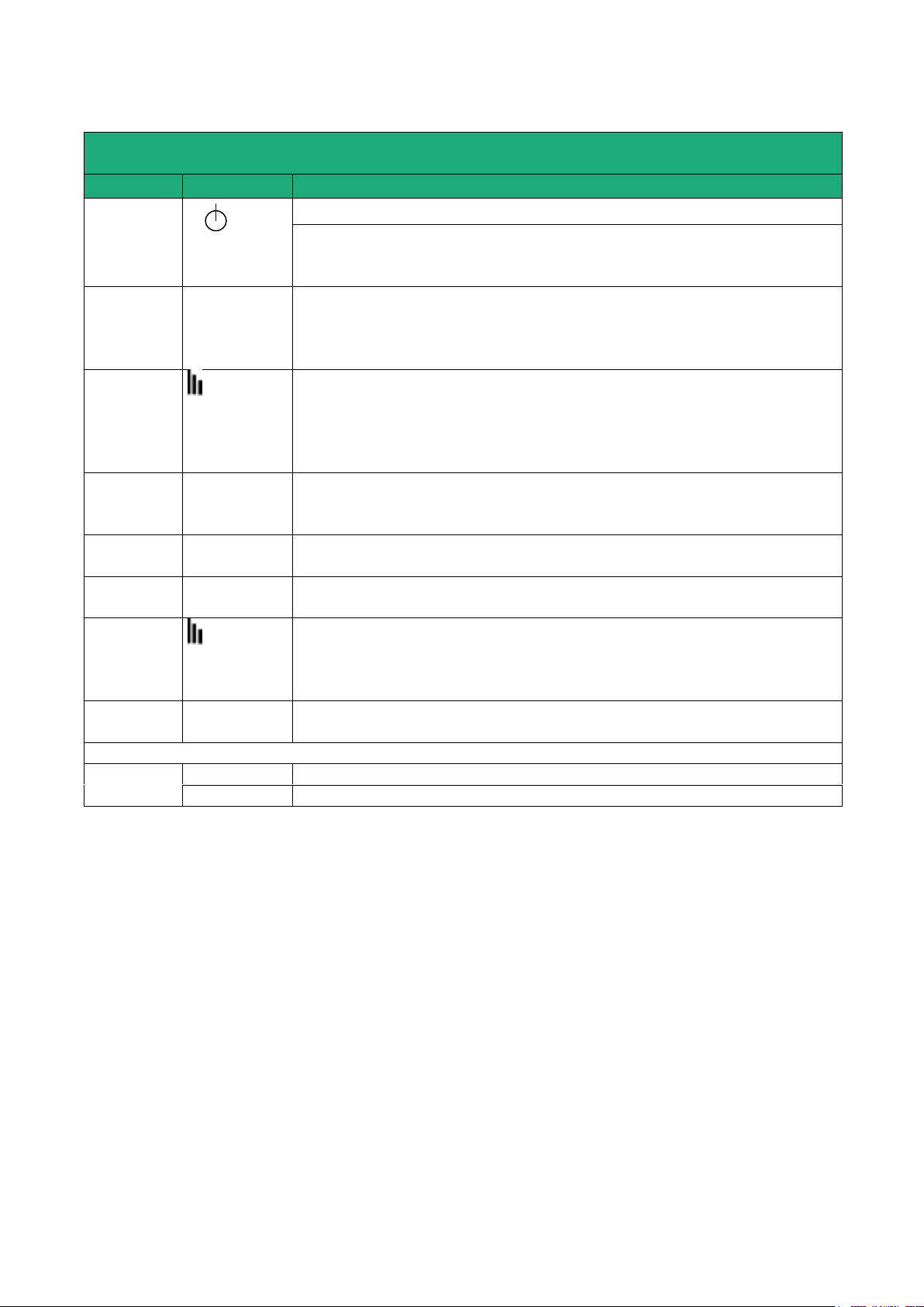
INSTALLATION
LED INDICATORS
RAS-EC-XYZ et RAS-ECW-XYZ
Designation
Fonction
Operation
Green The unit is ready
Red Power-up
The SIM card is not present
Hardware failure
Cellular
Connection
Cel
Off SIM card not present – cellular interface disabled
Flashing slowly Connection in progress (1st step)
Flashing fast Connection in progress (2nd step)
Green Connected to the cellular ntwk
Cellular
signal level
Cel
Off Cellular interface disabled
1 flash Faint not sufficient signal
2 flashes Sufficient signal
3 flashes Strong signal
See detail below
Ethernet
WAN
M2Me
Off Not connected to M2Me_Connect
Flashing Connection in progress
Green Connected
Ethernet
WAN
Voyant inférieur
Off Ethernet interface not connected
Green Ethernet interface connected
Wi-Fi
Connection
Wi-Fi
Off Wi-Fi Interface not enabled
Green Wi-Fi Interface enabled
Wi-Fi
signal level
Wi-Fi
Off Wi-Fi not enabled or enabled as an access point
1 flash Faint not sufficient signal
2 flashes Sufficient signal
3 flashes Strong signal
Ethernet LAN
1 to 4
Off Ethernet interface not connected
Green Ethernet interface connected
RAS-EC-220 RAS—ECW-220
RS232
RS485
Rx
Characters received from the serial interface (to the router RAS)
Tx
Characters transmitted to the serial interface (from the router RAS)
Page 38 DOC_DEV_RAS_User guide_A Machine Access Box RAS
Page 39
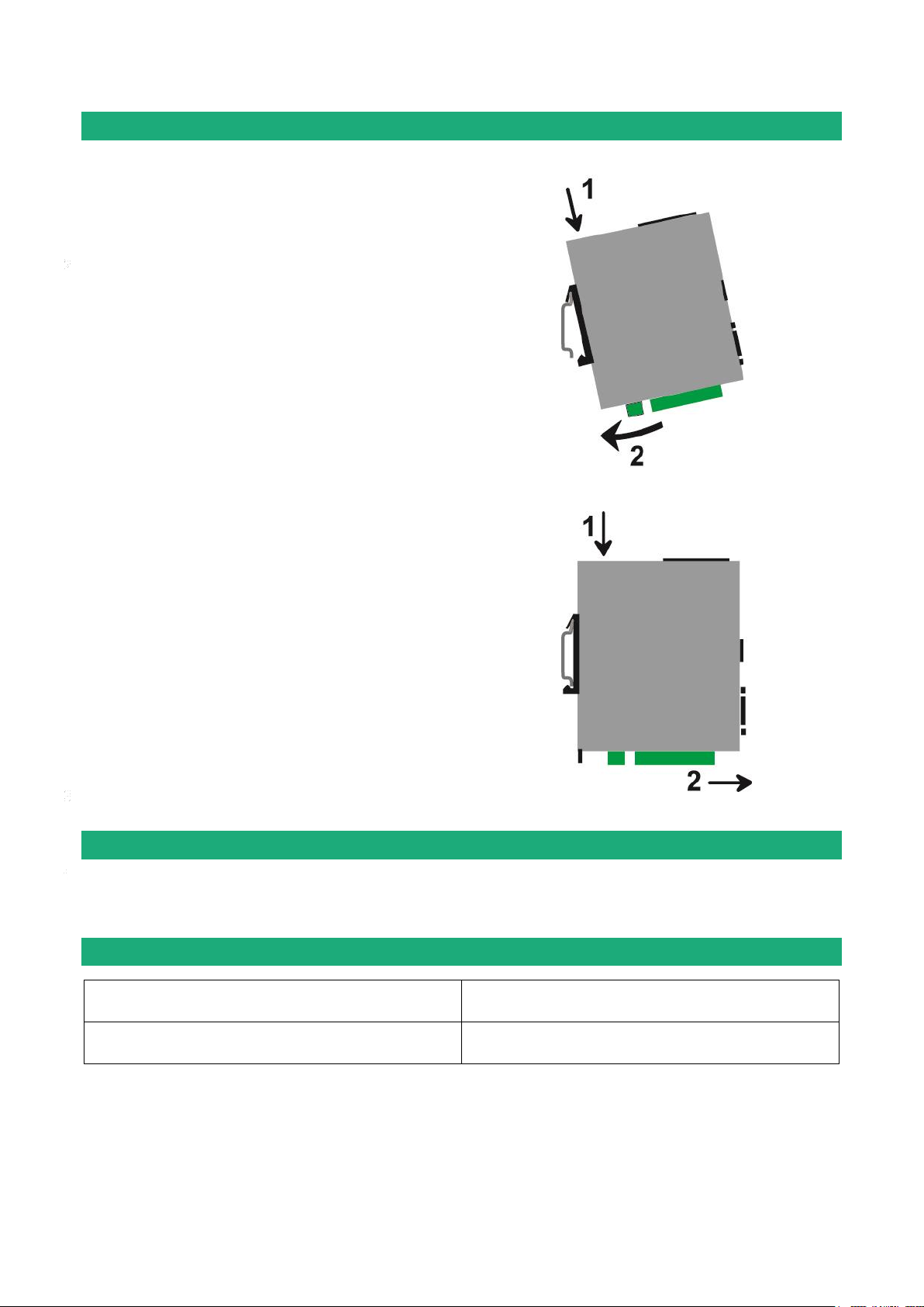
Mounting the product on a Din rail
Mounting the unit on the 35 mm horizontal DIN rail
Removing the unit from the DIN rail
RAS-E-400, RAS-EW-400
RAS-EC-400, RAS-ECW-400
Vmin : 10 V DC
Vmax = 60 V DC
RAS-E-220, RAS-EW-220, RAS-ECW-220
Vmin : 10 V DC
Vmax = 30 V DC
INSTALLATION
Cooling
To avoid obstructing the airflow around the unit, the spacing must be at least 25 mm above and below, and
10 mm left and right.
Supply voltage
The power is lower than 7W.
Machine Access Box RAS DOC_DEV_RAS_User guide_A Page 39
Page 40
INSTALLATION
RS232 cables (L=1m)
Code
User connector
Cable function
CAB592
SubD 9 male
To connect a DCE to the router RAS
CAB593
SubD 9 female
To connect a DTE to the router RAS
CAB609
Wires
To connect a device providing a specific connector
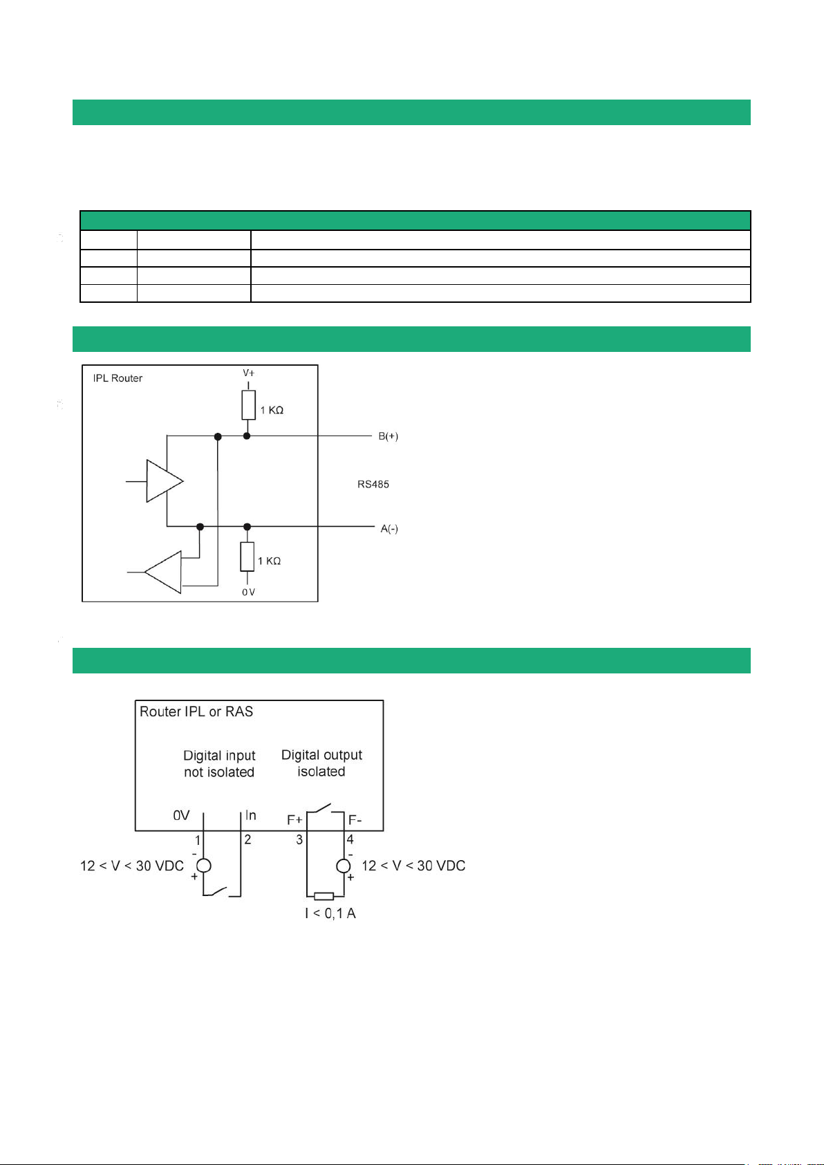
The RS485 serial interface is provided on the front
panel 2 positions screw-block.
It is not isolated.
Long RS485 line or high data rate
if the RS485 line is longer than10 meters or if the
data rate is greater than 19200 b/s, it is necessary
to connect one 120 Ohm matching resistor at each
end of the line and two 390 Ohm polarisation
resistors at one of the two extremities of the line.
To check that the input and the output are
correctly wired, select
Diagnostic > Hardware > Input / Output
The status of the input is displayed and
the output can be switched ON or OF.
RS232
The RS232 cable must be shorter than 10 meters.
Cables can be provided to connect the product to DTE and DCE as follows :
RS485 connection
Digital input and output
Page 40 DOC_DEV_RAS_User guide_A Machine Access Box RAS
Page 41

INSTALLATION
Connecting the router to the cellular network
8.1 Controls before installing the router
Autorisation to use a cellular connection
Check the cellular connection is authorised at the location where the router RAS is supposed to be installed.
Control of the reception level before installing the machine
Before installing the router, refer to a cell map over the Internet to check that the cellular reception signal is
strong enough at the location where the machine is supposed to be installed.
Select the right mobile service provider.
Reception level confirmation
If the reception seems possible, confirm with a control on site.
The reception level can be measured with a smartphone.
Most smartphones provide the reception level information (parameters or diagnostic menu).
To carry-out that control, use mandatorily a SIM card subscribed with the mobile service provider selected
for the router RAS.
Remark :
The router RAS itself provides the reception level information in two ways :
A reception level led indicator
The diagnostic menu of the administration web server of the router
8.2 Cellular antenna
We provide a complete catalog of cellular antennas :
Magnet mount antenna,
roof antenna,
ground plane antenna,
directive antenna,
omnidirectional antenna.
8.3 Coaxial cable
If necessary, the antenna can be connected to the router RAS through a coaxial cable.
The signal attenuation in a usual coaxial cable is 0,2 to 0.4 dB / m diameter , mm), that is to say 2 to 4 dB for
a 10 meter long cable.
If a coaxial cable must be used to connect the antenna to the router, the attenuation in the cable has to be
taken into account to calculate the effective RF signal received by the router RAS.
Refer to our cables and antennas catalogue.
Machine Access Box RAS DOC_DEV_RAS_User guide_A Page 41
Page 42
INSTALLATION
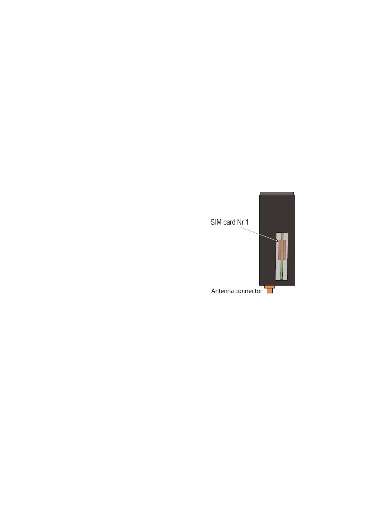
The router provides two SIM card holders. If you use only
one SIM card, use the SIM card holder Nr 1.
Power off the router.
Remove the anti-steal lid at the top of the product
Insert the SIM card according to the drawing
8.4 Cellular service subscription
The router RAS is designed to connect to the LTE-UMTS-GPRS data transmission service like the one used
by the tablets.
The subscription should also provide the SMS service if SMS alarms are required.
A telephone service subscription is not needed.
One will take care to subscribe to a service authorizing the right volume of data per month (MB/month) and
to check the price of the MB exceeding the limit of the subscription plan, if it exists.
The subscription must be preferably signed in the country where the machine is supposed to be installed to
avoid roaming costs.
8.5 Installing the SIM card
Page 42 DOC_DEV_RAS_User guide_A Machine Access Box RAS
Page 43
INSTALLATION
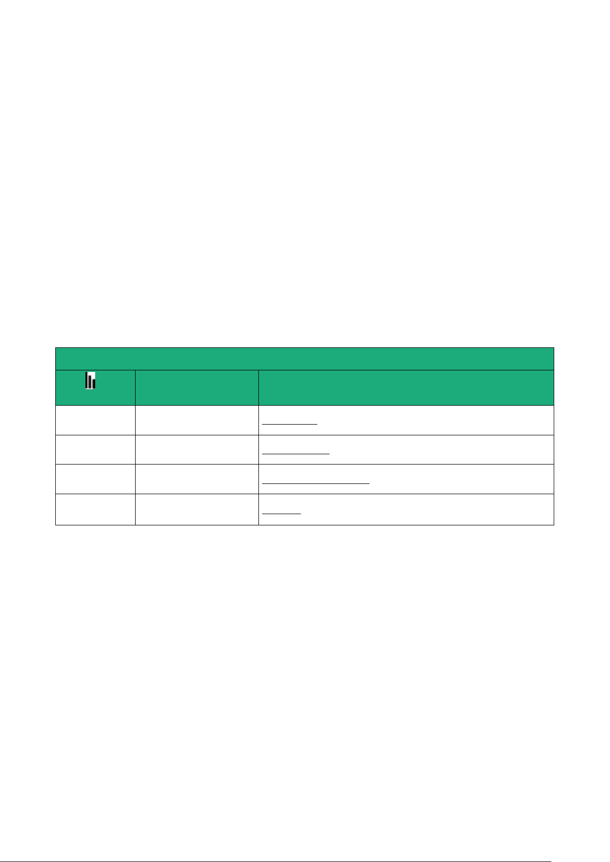
Cellular network reception level
Led
Reception level dBm (*)
3 flashs
-50 à - 80
Strong signal
2 flashs
-81 à –90
Sufficient signal
1 flash
-91 à -110
Weak not sufficient signal
Off
< -111
No signal
8.6 Controlling the conformance of the connection
After installing and setting up the router, control the conformance of the connection :
Reception level
The reception level must be better than -90 dBm (two flashes of the reception level led indicator).
See the table below.
PING error rate
Each PING request must receive an answer.
Network response delay to a PING request
The response delay must be better than 500 ms.
If the delay is longer than one second, it means the network is overloaded or that the signal level is weak.
If the connection is not conform, change the position of the antenna or select an alternative service like
UMTS instead of LTE for instance.
(*) See the web server menu Diagnostic > Network > Interface.
Machine Access Box RAS DOC_DEV_RAS_User guide_A Page 43
Page 44

Page 45
PREPARING THE PRODUCT SET-UP
First set-up
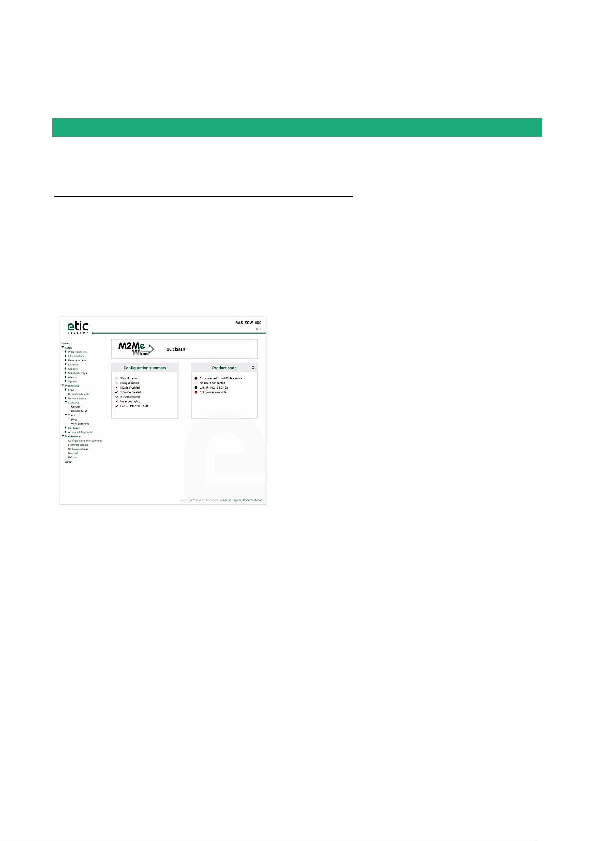
The first configuration is carried-out with an HTML browser and a PC to the Ethernet LAN port 1 to 4 of the
router RAS .
Coming from factory, the IP address of the router is 192.168.0.128.
Step 1 : Create or modify the PC IP connection.
Assign to the PC an IP @ in accordance with the router RAS IP address.
For the first configuration, assign for instance 192.168.0.127 to the PC.
Step 2 : Connect the PC directly to the LAN interface of the router RAS.
Step 3 : Launch the HTML browser : http://192.168.0.128
Machine Access Box RAS DOC_DEV_RAS_User guide_A Page 45
Page 46

PREPARING THE PRODUCT SET-UP
Protecting the access to the administration web server
Select Set-up > Security > Administration rights.
Enter an administration identifier and password.
Set-up modifications with HTTPS or through the WAN interface
The administration web server is located at the LAN IP address.
Coming from factory, access to the administration web server is not allowed through the WAN interface
To use HTTPS instead of HTTP to setup the product or to authorise access to the administration web server
through the WAN interface,
Select Configuration > Security > Administration rights.
Enter an administration identifier and password.
Check the “HTTPS configuration” box.
Check the “WAN access“ box if you wish to access to the administration web server through the WAN
interface.
Remark : the port Nr used to access to the administration web server with HTTPS is 4433.
Exemple : https://192.168.38.191:4433.
Recovering the factory LAN IP address
Press the front panel push-button ;
The OPERATION led indicator will flash.
The factory IP address 192.168.0.128 will be restored but the current configuration remains active.
Retour à la configuration Usine
If firewall rules have been created finally preventing from reaching any IP address on the LAN interface
including the router itself, it may be necessary to restore the factory configuration of the router.
To restore the RAS-3G factory configuration,
Switch OFF the power supply of the router RAS.
Press the rera panel push button and, switch-on the power supply.
Keep the push button pressed until the operation led turns red.
Remark : The curent configuration is cleared and the factory IP address 192.168.0.128 is restored.
Page 46 DOC_DEV_RAS_User guide_A Machine Access Box RAS
Page 47
SETTING-UP THE ROUTER WITH THE WIZARD
Use case
router RAS
models
Internet
access
Internet
interface
1
All router RAS
models
Factory network
Ethernet WAN
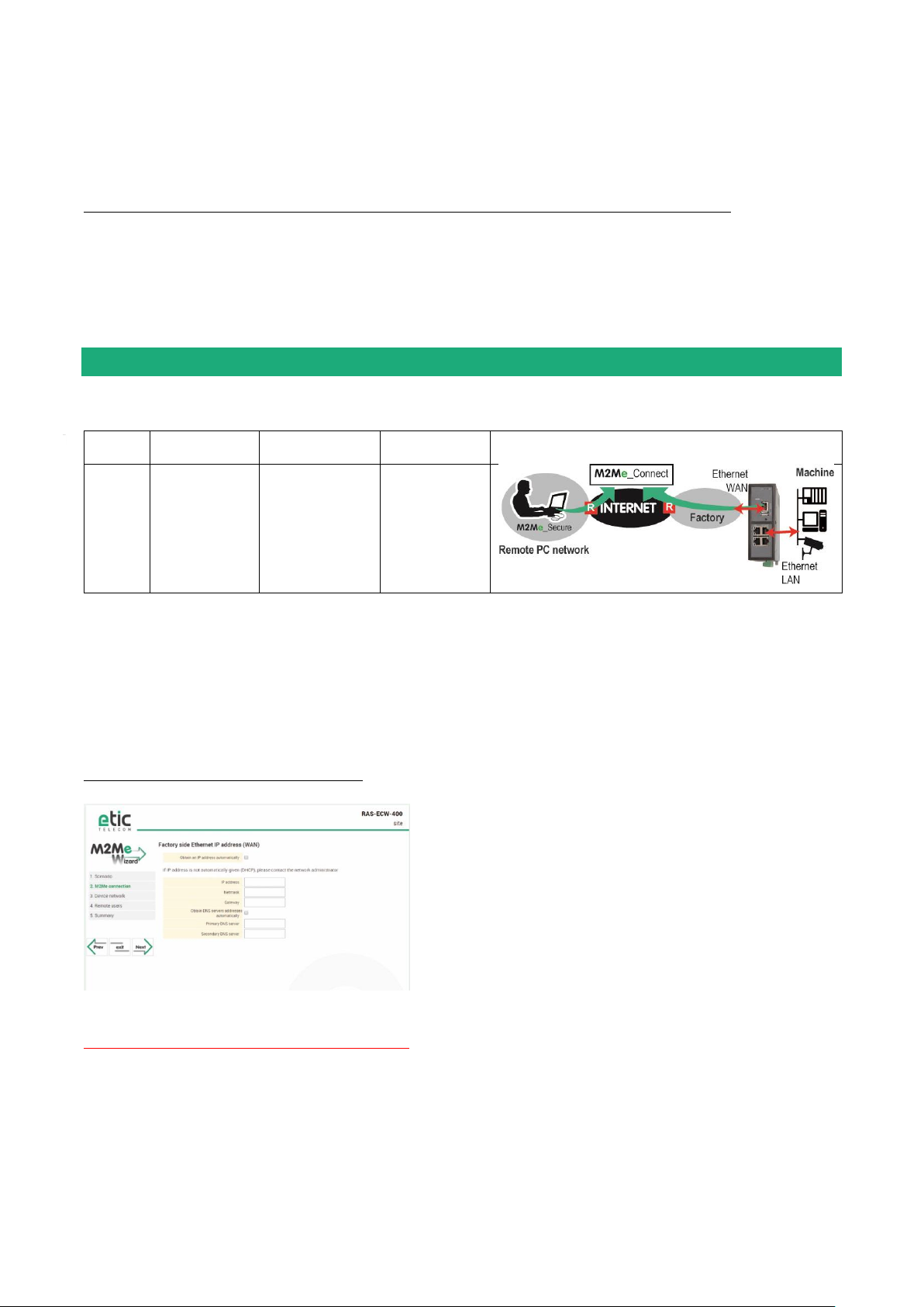
The Wizard simplifies the Internet connection set-up.
6 use cases can be selected (that 6 use cases have been described in the Overview chapter).
Once the Internet connection has been setup with the Wizard, the advanced setup mode makes possible to
setup other functions like SMS or email alarm and the firewall.
To set-up the product using the Wizard, launch the administration web server and click the Wizard button.
Use case 1 set-up
Le routeur RAS est connecté à un réseau d’usine ou d’entreprise par son interface Ethernet WAN.
STEP 1 : USE CASE SELECTION
Select the use case 1.
STEP 2 : M2Me CONNECTION
The « Ethernet WAN » page is displayed.
“Obtain an IP address automatically” checkbox :
Set that checkbox if the IP address is assigned automatically to the router RAS by a DHCP server.
Otherwise, unselect the check box and enter
The IP address assigned to the WAN interface of the router RAS,
The IP address of the default gateway on that IP network.
Machine Access Box RAS DOC_DEV_RAS_User guide_A Page 47
Page 48

SETTING-UP THE ROUTER WITH THE WIZARD
“Obtain DNS IP addresses automatically” checkbox :
Set that checkbox if the Domain name servers IP addresses are provided ent.
Otherwise enter the IP addresses of the DNS primary and secondary servers.
Click « Next «
The proxy server page is displayed.
« Direct access to the Internet (no proxy) » check box :
Leave that box not selected if no Proxy server exists on the WAN network.
Otherwise, select that checkbox and enter
the type of the proxy server (HTTP, SOCKS5)
the proxy IP address and port number
the type of required authentication (None, basic, NTLM) if the proxy is http
Click « Next «
Page 48 DOC_DEV_RAS_User guide_A Machine Access Box RAS
Page 49
SETTING-UP THE ROUTER WITH THE WIZARD
Examples :
Remote PC
network
Factory
network
Machine
network
OK
192.168.10.0
192.168.1.0
192.168.12.0
OK
192.168.10.0
192.168.10.0
192.168.12.0
The IP domain of the machine ntwk and of the
factory ntwk are the same.
The machine IP domain must be modified or the
RAS must be used according to the use case 2
192.168.10.0
192.168.1.0
192.168.1.0
The IP domain of the machine ntwk and of the
remote PC ntwk are the same.
The machine IP domain must be modified or the
address translation option must be selected (see
the wizard menu).
192.168.10.0
192.168.1.0
192.168.10.0
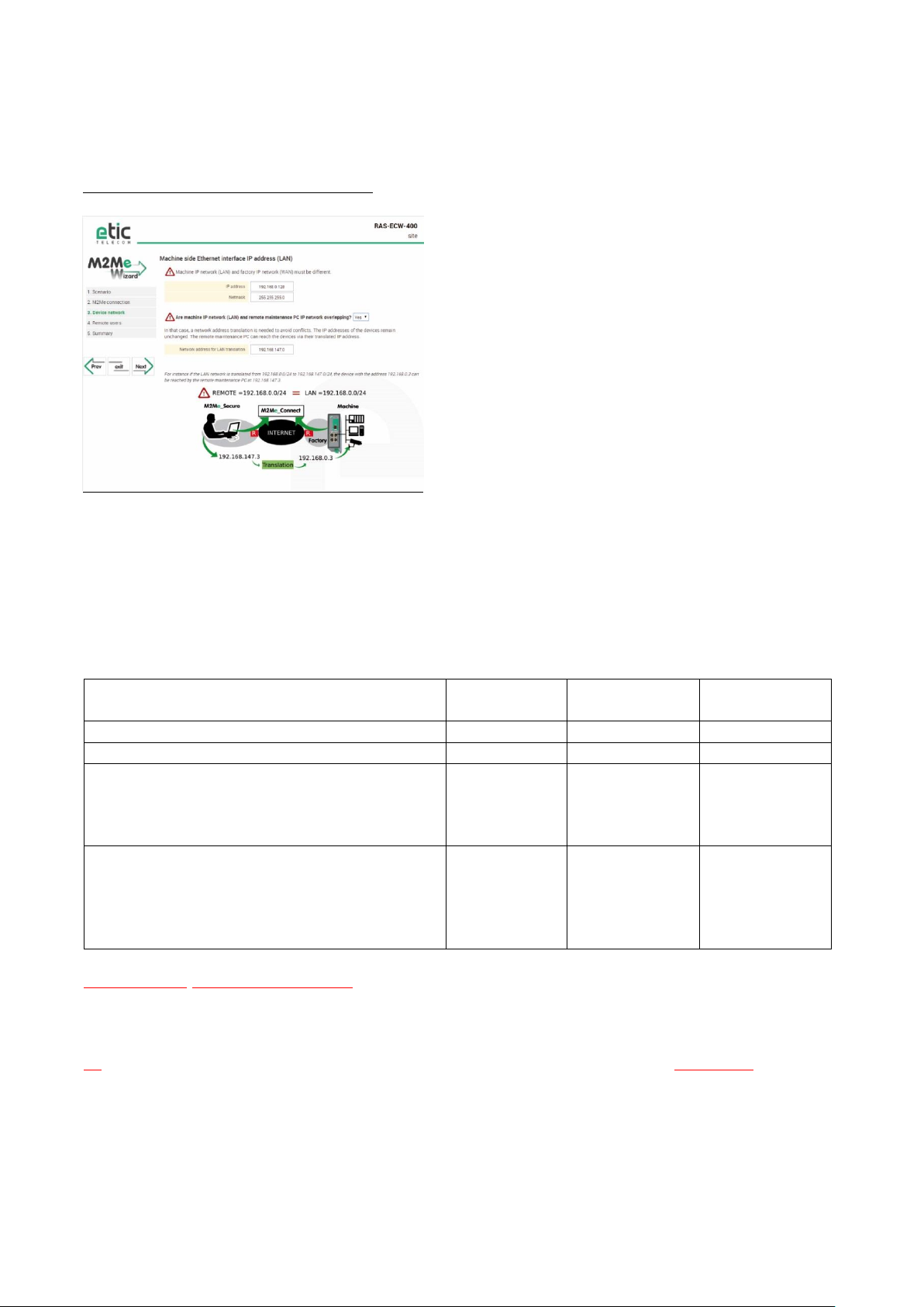
STEP 3 : MACHINE NETWORK
The “machine network” page is displayed.
Remark :
The IP domain of the machine network must mandatorily be different from the IP domain of the factory
network. Otherwise the IP addresses of each device of the machine must be modified.
The IP domain of the machine network must also be different form the IP domain of the remote PC.
Otherwise, the translation option described hereafter must be selected.
“IP address” & ”Netmask” parameters :
Enter the IP address assigned to the router over the LAN interface.
That IP address will have to be entered to display the administration server of the router.
«Are machine IP network (LAN) and remote maintenance PC IP network overlapping? Question :
If the answer is Yes, enter the translated IP domain assigned to the machine.
Click « Next«
Machine Access Box RAS DOC_DEV_RAS_User guide_A Page 49
Page 50

SETTING-UP THE ROUTER WITH THE WIZARD
The “Device list” page is displayed.
That page enables to store the devices list of the machine network.
The access right to each of these devices can be then assigned to each remote user.
To add a device to the devices list, click the “add » button and enter the name and the IP address of the
device.
If remote users are allowed to access to all the devices of the machine network, it is not useful to complete
the devices list.
Click « next «
STEP 4 : REMOTE USERS
The “Remote user” page is displayed
That page enables to store the authorized remote users list.
Remark :
Coming from factory, the ID and password of the remote users are checked but not the certificate.
To add a remote user, click the “add » button and enter the parameters of the remote user :
Full name, company name, Email address, telephone number, Remote user name & password.
Remark : the email address and telephone number of the remote user are useful if the alarm (SMS or mail)
function is required.
Click « next «
Page 50 DOC_DEV_RAS_User guide_A Machine Access Box RAS
Page 51

The “Access rights” page is displayed
The table of the access rights is displayed.
To assign a new right to a user,
click the “Add” button
select a user in the list
select a device in the list
Click the « Apply » button
SETTING-UP THE ROUTER WITH THE WIZARD
Machine Access Box RAS DOC_DEV_RAS_User guide_A Page 51
Page 52
SETTING-UP THE ROUTER WITH THE WIZARD
Use
case
Router RAS
models
Internet
access
interface to the
Internet
2
all
Factory
network
Ethernet LAN
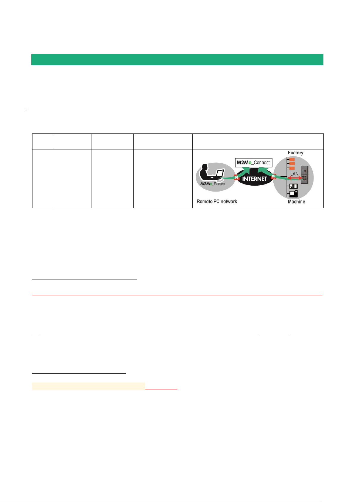
Use case 2 set-up
All the devices of machine belong to the factory network. The router RAS is also connected to the factory
network through its LAN interface.
Attention :
In that situation, a remote user can access remotely to all the devices connected to the network and not only
to the machine devices like in the Use case 1. it is why it is important to define strictly the authorised
devices and the access rights.
STEP 1 : SELECT THE USE CASE
Select the use case 2.
STEP 2 : M2Me CONNECTION
The « Ethernet LAN » page is displayed.
« IP address», « network mask », Default gateway», “Primary DNS server”, “Primary DNS server” parameters :
Enter the IP address assigned to the router over the LAN interface.
That IP address will have to be entered to display the administration server of the router.
Enter the DNS servers IP addresses and the defaukt gateway IP address (gateway to the Internet).
«Are machine IP network (LAN) and remote maintenance PC IP network overlapping? question :
If the answer is Yes, enter the translated IP domain assigned to the machine.
Click « Next»
The proxy server page is displayed.
« Direct access to the Internet (no proxy) » check box :
Leave that checkbox not selected if no Proxy server exists on the WAN network.
Otherwise, select that checkbox and enter
the type of the proxy server (HTTP, SOCKS5)
the proxy IP address and port number
the type of required authentication (None, basic, NTLM) if the proxy is http
Click « Next «
Page 52 DOC_DEV_RAS_User guide_A Machine Access Box RAS
Page 53

SETTING-UP THE ROUTER WITH THE WIZARD
STEP 3 : MACHINE NETWORK
The “Device list” page is displayed.
That page enables to store the devices list of the machine network.
The access right to each of these devices can be then assigned to each remote user.
To add a device to the devices list, click the “add » button and enter the name and the IP address of the
device.
If remote users are allowed to access to all the devices of the machine network, it is not useful to complete
the devices list.
Click « next «
STEP 4 : REMOTE USERS
The “Remote user” page is displayed
That page enables to store the authorized remote users list.
Remark :
Coming from factory, the ID and password of the remote users are checked but not the certificate.
To add a remote user, click the “add » button and enter the parameters of the remote user :
Full name, company name, Email address, telephone number, Remote user name & password.
Remark : the email address and telephone number of the remote user are useful if the alarm (SMS or mail)
function is required.
Click « next «
The “Access rights” page is displayed
The table of the access rights is displayed.
To assign a new right to a user,
click the “Add” button
select a user in the list
select a device in the list
Click the « Apply » button
Machine Access Box RAS DOC_DEV_RAS_User guide_A Page 53
Page 54
SETTING-UP THE ROUTER WITH THE WIZARD
Use case
router RAS
models
Internet
access
Internet interface
3
RAS-EC
RAS-ECW
Cellular network
Antenna
Examples :
Remote PC network
Machine network
OK
192.168.10.0
192.168.12.0
The IP domain of the machine ntwk and of the
remote PC ntwk are the same.
The machine IP domain must be modified or the
address translation option must be selected
192.168.10.0
192.168.10.0
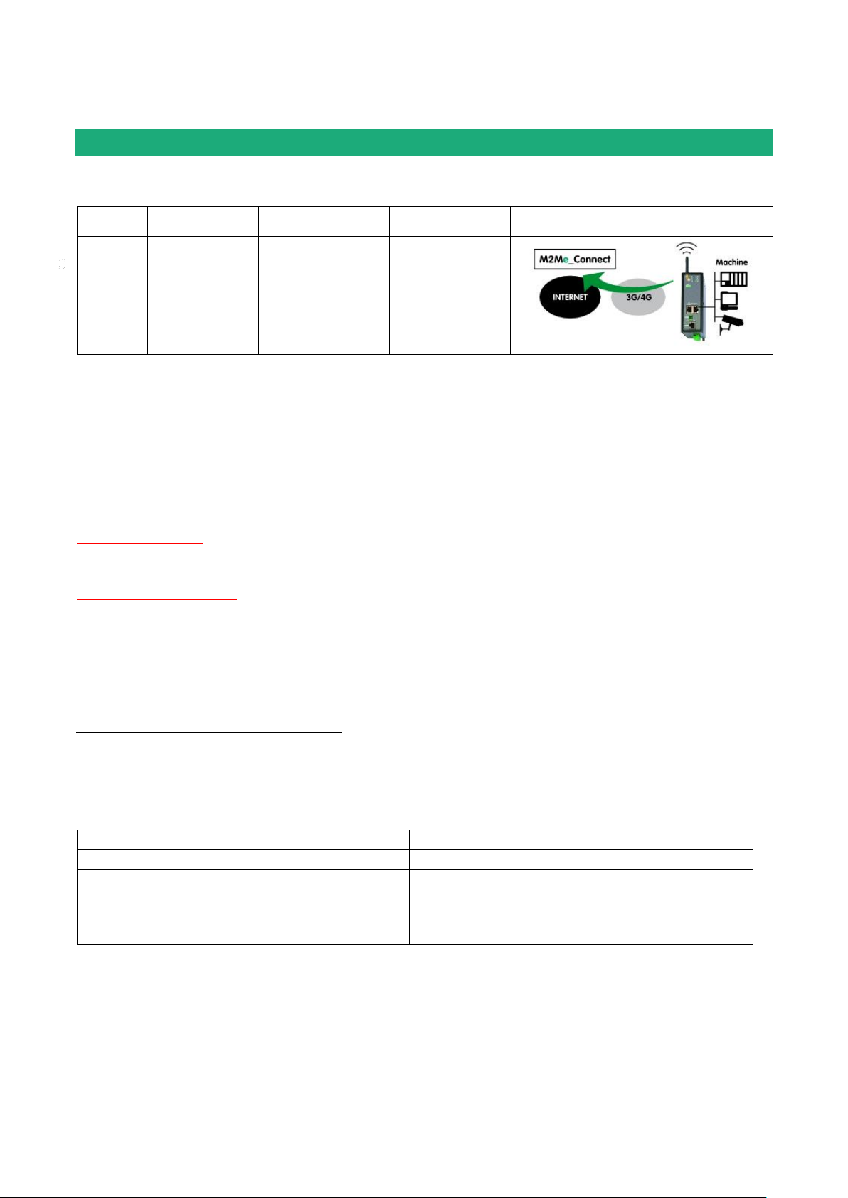
Use case 3 set-up
The machine is connected to the Internet through a cellular network
STEP 1 : SELECT THE USE CASE
Select the use case 3
STEP 2 : M2Me CONNECTION
The « cellular network » page is displayed.
« APN » parameter :
Enter the label of the Internet access point.
« PIN code » parameter :
Enter the SIM card PIN code.
Click « Next »
STEP 3 : MACHINE NETWORK
The “machine network” page is displayed.
Remark :
The IP domain of the machine network must also be different form the IP domain of the remote PC.
Otherwise, the translation option described hereafter must be selected.
“IP address” & ”Netmask” parameters :
Enter the IP address assigned to the router over the LAN interface.
That IP address will have to be entered to display the administration server of the router.
Page 54 DOC_DEV_RAS_User guide_A Machine Access Box RAS
Page 55

SETTING-UP THE ROUTER WITH THE WIZARD
«Are machine IP network (LAN) and remote maintenance PC IP network overlapping? question :
If the answer is Yes, enter the translated IP domain assigned to the machine.
Click « Next«
The “Device list” page is displayed.
That page enables to store the list of the devices belonging to the machine network.
The access right to each of these devices can be then assigned to each remote user.
To add a device to the devices list, click the “add » button and enter the name and the IP address of the
device.
If remote users are allowed to access to all the devices of the machine network, it is not useful to complete
the devices list.
Click « next «
STEP 4 : REMOTE USERS
The “Remote user” page is displayed
That page enables to store the authorized remote users list.
Remark :
Coming from factory, the ID and password of the remote users are checked but not the certificate.
To add a remote user, click the “add » button and enter the parameters of the remote user :
Full name, company name, Email address, telephone number, Remote user name & password.
Remark : the email address and telephone number of the remote user are useful if the alarm (SMS or mail)
function is required.
Click « next «
The “Access rights” page is displayed
The table of the access rights is displayed.
To assign a new right to a user,
click the “Add” button
select a user in the list
select a device in the list
Click the « Apply » button
Machine Access Box RAS DOC_DEV_RAS_User guide_A Page 55
Page 56
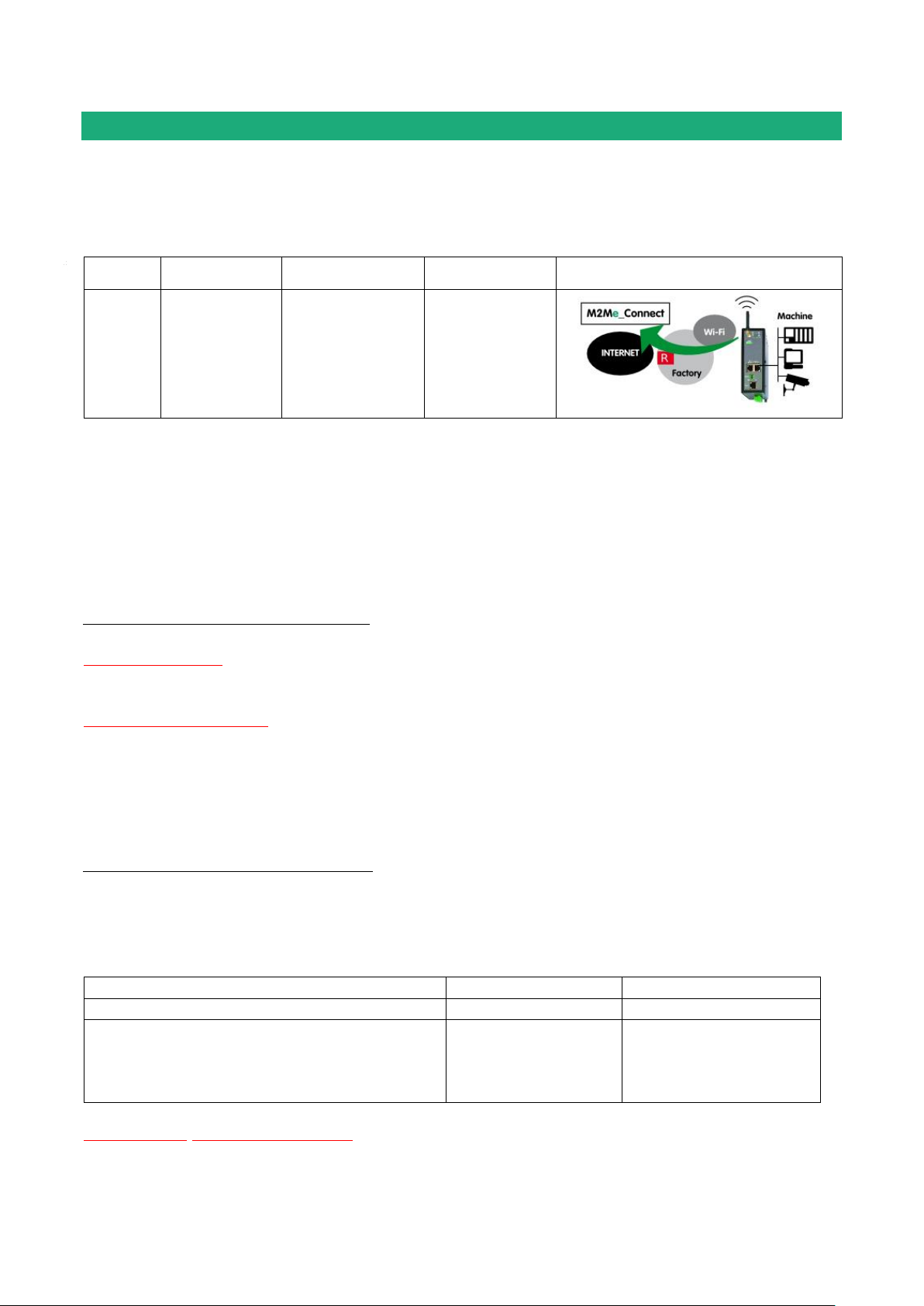
SETTING-UP THE ROUTER WITH THE WIZARD
Use case
router RAS
models
Internet access
Internet interface
3
RAS-EW
RAS-ECW
Wi-Fi network
Wi-Fi Antenna
Examples :
Remote PC network
Machine network
OK
192.168.10.0
192.168.12.0
The IP domain of the machine ntwk and of the
remote PC ntwk are the same.
The machine IP domain must be modified or the
address translation option must be selected
192.168.10.0
192.168.10.0
Use case 4 set-up
The machine is connected to the Internet through a Wi-Fi network.
The Wi-Fi interface of the router RAS is used as a Wi-Fi client ; it cannot be used at the same time as an
access point.
STEP 1 : USE CASE SELECTION
Select the use case Nr 6
STEP 2 : M2Me CONNECTION
The “Wi-Fi connection” page is displayed.
«SSID» Parameter :
Enter the label of the access point.
« Shared key » parameter :
Enter the WEP or WPA key of the access point.
Click « Next »
STEP 3 : MACHINE NETWORK
The “machine network” page is displayed.
Remark :
The IP domain of the machine network must also be different form the IP domain of the remote PC.
Otherwise, the translation option described hereafter must be selected.
“IP address” & ”Netmask” parameters :
Enter the IP address assigned to the router over the LAN interface.
That IP address will have to be entered to display the administration server of the router.
Page 56 DOC_DEV_RAS_User guide_A Machine Access Box RAS
Page 57

SETTING-UP THE ROUTER WITH THE WIZARD
«Are machine IP network (LAN) and remote maintenance PC IP network overlapping? question :
If the answer is Yes, enter the translated IP domain assigned to the machine.
Click « Next«
The “Device list” page is displayed.
That page enables to store the list of the devices belonging to the machine network.
The access right to each of these devices can be then assigned to each remote user.
To add a device to the devices list, click the “add » button and enter the name and the IP address of the
device.
If remote users are allowed to access to all the devices of the machine network, it is not useful to complete
the devices list.
Click « next «
STEP 4 : REMOTE USERS
The “Remote user” page is displayed
That page enables to store the authorized remote users list.
Remark :
Coming from factory, the ID and password of the remote users are checked but not the certificate.
To add a remote user, click the “add » button and enter the parameters of the remote user :
Full name, company name, Email address, telephone number, Remote user name & password.
Remark : the email address and telephone number of the remote user are useful if the alarm (SMS or mail)
function is required.
Click « next «
The “Access rights” page is displayed
The table of the access rights is displayed.
To assign a new right to a user,
click the “Add” button
select a user in the list
select a device in the list
Click the « Apply » button
Machine Access Box RAS DOC_DEV_RAS_User guide_A Page 57
Page 58
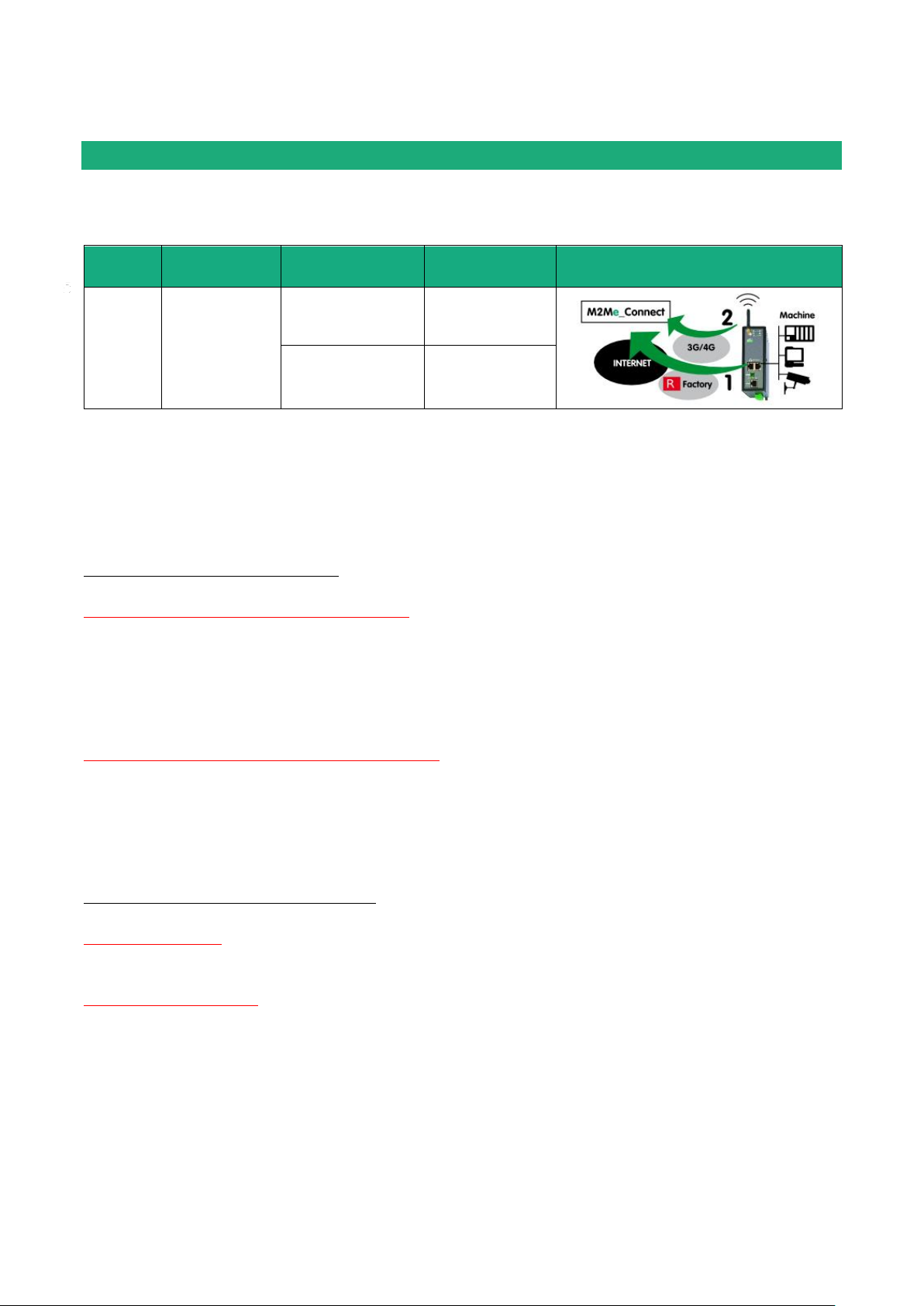
SETTING-UP THE ROUTER WITH THE WIZARD
Use
case
Models
Way to the
Internet
Internet
interface
5
RAS-EC
RAS-ECW
Factory network
Ethernet WAN
Cellular network
Cellular antenna
Use case 5 set-up
The machine is connected to the Internet through the factory network as a priority and also through the
cellular network as a backup path. The router RAS switches automatically.
STEP 1 : USE CASE SELECTION
Select the use case 5.
STEP 2 : M2Me CONNECTION
The «Main WAN » page is displayed.
“Obtain an IP address automatically” checkbox :
Set that checkbox if the IP address is assigned automatically to the router RAS by a DHCP server.
Otherwise, unselect the check box and enter
The IP address assigned to the WAN interface of the router RAS,
The IP address of the default gateway on that IP network.
“Obtain DNS IP addresses automatically” checkbox :
Set that checkbox if the Domain name servers IP addresses are provided ent.
Otherwise enter the IP addresses of the DNS primary and secondary servers.
Click « Next «
The « cellular network » page is displayed.
« APN » parameter :
Enter the label of the Internet access point.
« PIN code » parameter :
Enter the SIM card PIN code.
Click « Next »
Page 58 DOC_DEV_RAS_User guide_A Machine Access Box RAS
Page 59

SETTING-UP THE ROUTER WITH THE WIZARD
Examples :
Remote PC
network
Factory
network
Machine
network
OK
192.168.10.0
192.168.1.0
192.168.12.0
OK
192.168.10.0
192.168.10.0
192.168.12.0
The IP domain of the machine ntwk and of the
factory ntwk are the same.
The machine IP domain must be modified or the
RAS must be used according to the use case 2
192.168.10.0
192.168.1.0
192.168.1.0
The IP domain of the machine ntwk and of the
remote PC ntwk are the same.
The machine IP domain must be modified or the
address translation option must be selected (see
the wizard menu).
192.168.10.0
192.168.1.0
192.168.10.0
STEP 3 : MACHINE NETWORK
The “machine network” page is displayed.
Remark :
The IP domain of the machine network must mandatorily be different from the IP domain of the factory
network. Otherwise the IP addresses of each device of the machine must be modified.
The IP domain of the machine network must also be different form the IP domain of the remote PC.
Otherwise, the translation option described hereafter must be selected.
“IP address” & ”Netmask” parameters :
Enter the IP address assigned to the router over the LAN interface.
That IP address will have to be entered to display the administration server of the router.
«Are machine IP network (LAN) and remote maintenance PC IP network overlapping? Question :
If the answer is Yes, enter the translated IP domain assigned to the machine.
Click « Next«
The “Device list” page is displayed.
That page enables to store the devices list of the machine network.
The access right to each of these devices can be then assigned to each remote user.
To add a device to the devices list, click the “add » button and enter the name and the IP address of the
device.
If remote users are allowed to access to all the devices of the machine network, it is not useful to complete
the devices list.
Click « next «
Machine Access Box RAS DOC_DEV_RAS_User guide_A Page 59
Page 60

SETTING-UP THE ROUTER WITH THE WIZARD
STEP 4 : REMOTE USERS
The “Remote user” page is displayed
That page enables to store the authorized remote users list.
Remark :
Coming from factory, the ID and password of the remote users are checked but not the certificate.
To add a remote user, click the “add » button and enter the parameters of the remote user :
Full name, company name, Email address, telephone number, Remote user name & password.
Remark : the email address and telephone number of the remote user are useful if the alarm (SMS or mail)
function is required.
Click « next «
The “Access rights” page is displayed
The table of the access rights is displayed.
To assign a new right to a user,
click the “Add” button
select a user in the list
select a device in the list
Click the « Apply » button
Page 60 DOC_DEV_RAS_User guide_A Machine Access Box RAS
Page 61

SETTING-UP THE ROUTER WITH THE WIZARD
Use
case
Models
Way to the
Internet
Internet
interface
6
RAS-EC
RAS-ECW
Wi-Fi network
Wi-Fi antenna
Cellular network
Cellular antenna
Use case 6 set-up
The machine is connected to the Internet through the Wi-Fi network as a priority and also through the
cellular network as a backup path. The router RAS switches automatically.
STEP 1 : USE CASE SELECTION
Select the use case 6.
STEP 2 : M2Me CONNECTION
The “Wi-Fi connection (Main WAN)” page is displayed.
«SSID» Parameter :
Enter the label of the access point.
« Shared key » parameter :
Enter the WEP or WPA key of the access point.
Click « Next »
The « cellular network (Backup WAN)» page is displayed.
« APN » parameter :
Enter the label of the Internet access point.
« PIN code » parameter :
Enter the SIM card PIN code.
Click « Next »
Machine Access Box RAS DOC_DEV_RAS_User guide_A Page 61
Page 62

SETTING-UP THE ROUTER WITH THE WIZARD
Examples :
Remote PC
network
Factory
network
Machine
network
OK
192.168.10.0
192.168.1.0
192.168.12.0
OK
192.168.10.0
192.168.10.0
192.168.12.0
The IP domain of the machine ntwk and of the
factory ntwk are the same.
The machine IP domain must be modified or the
RAS must be used according to the use case 2
192.168.10.0
192.168.1.0
192.168.1.0
The IP domain of the machine ntwk and of the
remote PC ntwk are the same.
The machine IP domain must be modified or the
address translation option must be selected (see
the wizard menu).
192.168.10.0
192.168.1.0
192.168.10.0
STEP 3 : MACHINE NETWORK
The “machine network” page is displayed.
Remark :
The IP domain of the machine network must mandatorily be different from the IP domain of the factory
network. Otherwise the IP addresses of each device of the machine must be modified.
The IP domain of the machine network must also be different form the IP domain of the remote PC.
Otherwise, the translation option described hereafter must be selected.
“IP address” & ”Netmask” parameters :
Enter the IP address assigned to the router over the LAN interface.
That IP address will have to be entered to display the administration server of the router.
«Are machine IP network (LAN) and remote maintenance PC IP network overlapping? Question :
If the answer is Yes, enter the translated IP domain assigned to the machine.
Click « Next«
Page 62 DOC_DEV_RAS_User guide_A Machine Access Box RAS
Page 63

SETTING-UP THE ROUTER WITH THE WIZARD
The “Device list” page is displayed.
That page enables to store the devices list of the machine network.
The access right to each of these devices can be then assigned to each remote user.
To add a device to the devices list, click the “add » button and enter the name and the IP address of the
device.
If remote users are allowed to access to all the devices of the machine network, it is not useful to complete
the devices list.
Click « next «
STEP 4 : REMOTE USERS
The “Remote user” page is displayed
That page enables to store the authorized remote users list.
Remark :
Coming from factory, the ID and password of the remote users are checked but not the certificate.
To add a remote user, click the “add » button and enter the parameters of the remote user :
Full name, company name, Email address, telephone number, Remote user name & password.
Remark : the email address and telephone number of the remote user are useful if the alarm (SMS or mail)
function is required.
Click « next «
The “Access rights” page is displayed
The table of the access rights is displayed.
To assign a new right to a user,
click the “Add” button
select a user in the list
select a device in the list
Click the « Apply » button.
Machine Access Box RAS DOC_DEV_RAS_User guide_A Page 63
Page 64

Page 65

ADVANCED SET-UP
Function
Menu
Internet connection set-up
Ethernet WAN
Cellular network
Wi-Fi network (the router RAS is a Wi-Fi client)
WAN interface
LAN interface set-up
The Ethernete & IP setup of the router RAS LAN interface
The IP adrresses of the devices of the machine
LAN Interface
Remote access set-up
The M2Me connection
The remote users
Their access rights
Remote access
IP routing
VPNs
Static routes
RIP
Address translation
Port forwarding
DynDNS or NoIP
Network
Filtering the data-flow between the LAN interface on one hand
and the WAN and VPN interfaces on the other hand
Security > Firewall
Serial gateway set-up
Serial gateway
Email or SM Alarm
Alarm
Administration web server access
Security > Administration rights
The advanced configuration mode allows to set-up step by step all the functions provided by the router RAS.
Machine Access Box RAS DOC_DEV_RAS_User guide_A Page 65
Page 66

ADVANCED SET-UP
Internet access set-up
1.1 Overview
Depending on the router RAS model, the following interfaces are provided.
Ethernet WAN (all models),
Cellular,
Wi-Fi as a client,
Ethernet LAN (all models),
1.2 Ethernet / WAN interface
Select the “Set-up > WAN > Ethernet” menu
Ethernet WAN port
« Speed / Duplex» parameter :
Select 10 or 100 Mb/s & full or half duplex.
IP set-up of the Ethernet WAN port
« Connection type » list :
The Ethernet choice is the usual choice to set a connection to the Internet.
The PPPOE choice must be selected only in a particular situation :
It If it it selected, the router RAS sets a PPP connection over Ethernet towards a service provider for instance.
It is useful when a modem, not supporting PPOE, is connected to the Ethernet WAN port of the router RAS.
Do not select PPOE except in the situation described above.
Page 66 DOC_DEV_RAS_User guide_A Machine Access Box RAS
Page 67

ADVANCED SET-UP
Choice
Ethernet
PPPoE
“Priority” parameter
That parameter defines the priority of the path when more than one path
is selected (Cellular & Ethernet WAN, for instance).
The router will use as a priority the path to which the highest value is
assigned; the other pat wil be used as a backup path.
« PPP login» et « PPP password » parameters
Enter the login and password of the PPP connection
« Obtain an IP address automatically » checkbox:
Leave that checkbox selected if the IP address on the WAN interface is
assigned by a DHCP server.
Otherwise unselect that checkbox and enter the IP address, the
netwmask and the default gateway address.
« Obtain the DNS server IP address automatically » checkbox:
Leave that checkbox selected if the DNS servers IP address are
assigned by a DHCP server.
Otherwise unselect that checkbox and enter the IP addresses of the DNS
servers.
« NAT» checkbox :
If that option is selected, the source IP address of any IP frame coming
from a device connected to the LAN interface and routed to the WAN
interface , is replaced by the router WAN IP address.
Remark : Select that checkbox if a device of the LAN interface needs to
set a connection with a device connected to the Internet (FTP server …)
« Proxy-Arp » checkbox :
Leave that checkbox unselected
Machine Access Box RAS DOC_DEV_RAS_User guide_A Page 67
Page 68

ADVANCED SET-UP
SIM card parameter
Value
SIM1
The SIM 1 is selected (default value)
SIM2
The SIM 2 is selected (default value)
SIM 1, backup to SIM2
The SIM 1 is used first ; the SIM 2 is used as backup
1.3 Cellular network interface
Two SIM cards can be inserted in the router to allow the use of two different cellular networks .
The network corresponding o the SIM card Nr1 is the main network, while the other one is the backup
network.
To set-up the cellular network interface, select Set-up > WAN interface
« Connection type » list :
Select the « cellular” choice.
“Priority” parameter
That parameter defines the priority of the path when more than one path is selected (Cellular & Ethernet
WAN, for instance).
The router will use first the interface having received the highest priority; the other interface will be used as a
backup path.
“SIM card” parameter
It is possible to select the SIM card Nr1, or the SIM card Nr2 or both.
1.3.1 SIM 1 or SIM 2 set-up
Setting-up the SIM card 1 or the SIM card 2 is identical. We describe hereafter the SIM 1 set-up.
SIM 1 : Modem set-up
« Modem initialisation string » parameter :
Leave that field empty.
« APN » parameter :
Enter the label of the gateway (APN) to the Internet - or to other services - provided by the mobile service
provider.
« PIN code » parameter :
Enter the SIM card pin code.
As long as the PIN code has not been correctly entered, the OPERATION led indicator flashes (red color).
Page 68 DOC_DEV_RAS_User guide_A Machine Access Box RAS
Page 69

ADVANCED SET-UP
« Cellular network » parametr :
The router RAS is supposed to connect to the best cellular relay available.
However, in particular situations, it may be useful to force the router RAS to use a particular service.
That parameter gives the choice to select either the LTE 4G service, or the UMTS 3G service or the GPRSEDGE service.
The default value is “AUTO”; in that case, the router RAS selects the best available connection.
Cellular IP interface set-up
«Login» & « Password» parameters :
Enter the login and password of the subscription.
Remark : That parameters are generally not required.
« Obtain an P address automatically » checkbox :
The IP address of the cellular interface of the router RAS is usually assigned by the service provider over the
air.
Otherwise, enter the IP address assigned to the cellular interface of the router.
« Obtain the DNS server IP address automatically » checkbox:
Leave that checkbox selected if the DNS servers IP address are assigned by a DHCP server.
Otherwise unselect that checkbox and enter the IP addresses of the DNS servers.
« NAT» checkbox :
If that option is selected, the source IP address of any IP frame coming from a device connected to the LAN
interface and routed to the WAN interface , is replaced by the router WAN IP address.
Remark : Select that checkbox if a device of the LAN interface needs to set a connection with a device
connected to the Internet (FTP server …).
1.3.2 Using the SIM cards 1 and 2
Each SIM card can be associated to two different mobiles data services.
In the subsequent text, the cellular service associated to the SIM card 1 is referred to as Network 1 and the
cellular service associated to the SIM card 2 as the Network 2.
The network 1 is first service tested at power-up.
If the Network 1 remains in failure during the period of time T1, the router switches to the network 2.
If the Network 2 is functioning properly, the router uses that cellular network at least during the period of
time T3.
On expiry of that period, the router switches back to the network 1 and checks if it is available. If it is not the
router goes on using the Network 2.
At any time, If the network 2 does not work correctly during the period of time T2, the router switches to
Network 1.
The periods of time T1, T2 and 3 can be set.
We advise not to select too small values of the T1, T2 and T3 parameters. :
Machine Access Box RAS DOC_DEV_RAS_User guide_A Page 69
Page 70

ADVANCED SET-UP
Example :
T1 Network 1 failure confirmation time = 20 mn
T1 Network 2 failure confirmation time = 20 mn
T3 Minimum connection time on network 2 = 12 hours
«Network 1 failure confirmation time » parameter
See above.
Value : 5, 10, 20, 30, 60 mn
«Network 2 failure confirmation time » parameter
See above.
Value : 5, 10, 20, 30, 60 mn
«Minimum connection time on Network 2» :
See above.
Value : 1, 12, 24 hours, 5 days, never.
1.3.3 Cellular connection control
The router RAS checks permanently that the cellular connection is properly set thanks to the PPP protocol
established with the cellular infrastructure router.
However, with particular mobile service providers, or in particular situations, that PPP connection is declared
active while the data transmission service is not provided by the mobile service provider.
It is why the router RAS is able to ping a particular server to check if the data service is really provided. If it
is not, the PPP connection is reset.
That function must be enabled only if connection defects are noticed.
To implement that function, enter the parameters hereafter.
«IP address of the server» parameter :
Enter the IP address of the device to which the router RAS will send a periodic ICMP message (PING)
«PING Interval” parameter :
Enter the period of the PINGs
Value : 30 s, 1, 2, 5, 10, 20, 30, 60 mn
«Number of retries» parameter :
Enter the number of retries before resetting the PPP connection.
Value : 1, 2, 4, 8, 12
Page 70 DOC_DEV_RAS_User guide_A Machine Access Box RAS
Page 71

ADVANCED SET-UP
1.4 Wi-Fi interface setup
Remark :
The Wi-Fi scanner makes possible to detect the Wi-Fi networks around the router RAS.
To use the Wi-Fi scanner, select the Diagnostic > Tools > Wi-Fi scanner menu.
To set-up the Wi-Fi interface as a client to reach the Internet,
Select Set-up > WAN interfaces > Wi-Fi
Select the « Enable » checkbox
Wi-Fi modem set-up
« Network name (SSID) » parameter :
Enter the name assigned to the Wi-Fi network to which the router RAS has to connect.
Attention : The SSID is case sensitive.
« Authentification » parameter :
Select WPA or WEP or None according to the access point set-up.
« Key » parameter :
Enter the WPA or WEP key according to the access point set-up.
Wi-Fi WAN IP set-up
« Wi-Fi WAN priority» parameter :
Saisir la valeur 10.
« Obtain an IP address automatically » checkbox:
Leave that checkbox selected if the IP address on the WAN interface is assigned by a DHCP server.
Otherwise unselect that checkbox and enter the IP address, the netwmask and the default gateway address.
« Obtain the DNS server IP address automatically » checkbox:
Leave that checkbox selected if the DNS servers IP address are assigned by a DHCP server.
Otherwise unselect that checkbox and enter the IP addresses of the DNS servers.
« NAT» checkbox :
If that option is selected, the source IP address of any IP frame coming from a device connected to the LAN
interface and routed to the WAN interface , is replaced by the router WAN IP address.
Remark : Select that checkbox if a device of the LAN interface needs to set a connection with a device
connected to the Internet (FTP server …)
Machine Access Box RAS DOC_DEV_RAS_User guide_A Page 71
Page 72
ADVANCED SET-UP
IP address
Remark
LAN network
192.168.12.0 / 24
From 192.168.12.1 to 192.168.12.254
Netmask
255.255.255.0
Router RAS IP addr.
192.168.12.1
Remote users IP pool start
192.168.12.2
Two remote users can simultaneously connect to
the LAN network; one will receive the IP address
192.168.12.2 and the other 192.168.12.3.
Remote users IP pool end
192.168.12.3
IP addresses available for the
devices of the LAN network
192.168.12.4 to
192.168.12.254
LAN interface
2.1 Overview
Ethernet switch or hub
The LAN interface consists of 1 to 4 switched Ethernet 10/100 BT RJ45 connectors.
An option enables to shape a hub instead of a switch for test purposes for instance.
IP address of the router RAS on the LAN interface
A fixed IP address must be assigned to the LAN interface of the router RAS.
DHCP server
The router RAS can also behave like a DHCP server for the devices on the LAN interface.
Remote users IP addresses allocation
If remote users PCs are supposed to connect to the devices of the LAN network, a pool of IP addresses
belonging to the LAN network has to be reserved for them.
The addresses reserved for the remote users must not be allocated to other devices of the LAN network.
Example :
Identification of the devices connected to the LAN network
The identification of the devices connected to the LAN network can be stored into the router.
The access to an identified device can then e allocated individually to the remote users.
Wi-Fi access point
When the optional Wi-Fi interface is set-up as an access point, the devices connected to the router RAS
through that Wi-Fi network belong to LAN network.
As a consequence, their IP address belong to the IP domain of the LAN network.
Page 72 DOC_DEV_RAS_User guide_A Machine Access Box RAS
Page 73
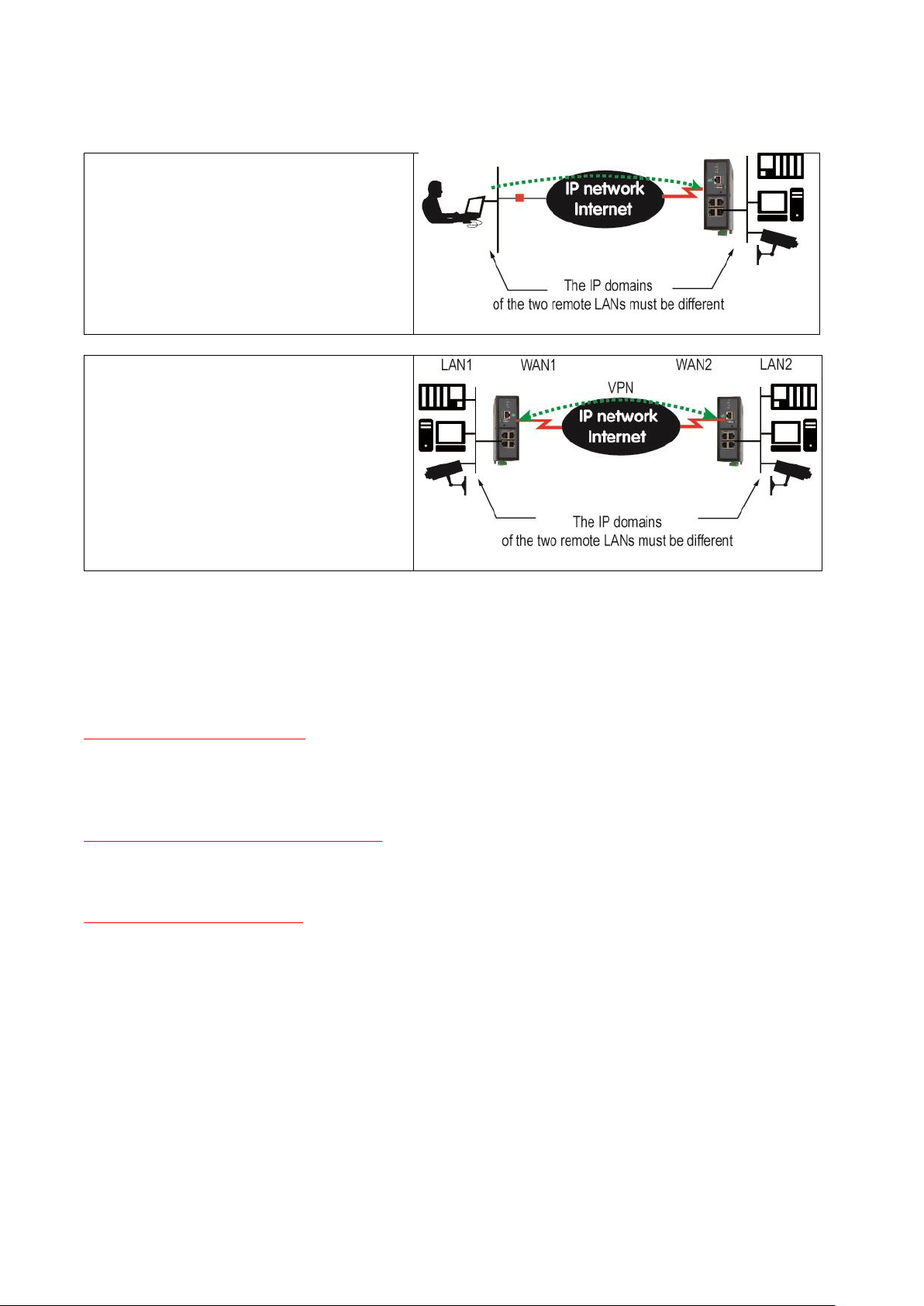
IP adresses allocation
Case 1 : Remote users connection
Case 2 : VPN set between 2 routers
ADVANCED SET-UP
2.2 Ethernet & IP menu
Select Set-up > LAN Interface > Ethernet & IP
Ethernet ports
« hub mode enable» checkbox :
If the checkbox is selected, the LAN ports behaves like a hub.
LAN network
« IP address » & « netsmask » parameters :
Enter the IP address assigned to the router over the LAN interface.
That IP address is also the IP address of the administration server of the router.
« Default gateway » parameter :
If another router is connected to the LAN network giving access to other networks, and acting as the default
gateway for the router RAS, enter the address of the router.
Remark : leave that field empty, if no othe rrouter is conected to the LAN network.
Machine Access Box RAS DOC_DEV_RAS_User guide_A Page 73
Page 74

ADVANCED SET-UP
Remote access menu
«Automatic management of the remote users» checkbox :
If that checkbox is selected, the router RAS allocates automatically an unused IP address of the LAN
network to a remote user when he connects.
Unselect that checkbox to set-up the pool of fixed IP addresses which can be allocated to the remote users.
That IP addresses must belong to the LAN domain.
Advanced parameters
Page 74 DOC_DEV_RAS_User guide_A Machine Access Box RAS
Page 75

ADVANCED SET-UP
2.3 Wi-Fi access point set-up
Remark : The Wi-Fi module can be set-up either like a client or like an access point.
To set-up the Wi-Fi access point,
Select the Set-up > LAN interface > Wi-Fi acces point menu
Select the Wi-Fi access point checkbox
« Network name (SSID) » parameter :
Enter the name assigned to the Wi-Fi network to which the router RAS has to connect.
Attention : The SSID is case sensitive.
« Preshared key » parameter :
Enter the WPA preshared key (at least 8 characters).
« Country code» parameter :
The RF channels allocated to the Wi-Fi service are not the same in all the countries.
It is why, the country code has to be entered carefully.
Click the help menu to display the list of the country codes.
« Wi-Fi Mode» parameter :
Select one of the possible Wi-Fi modes :
Mode 802.11a : 5 GHz OFDM
Mode 802.11.b : 2,4 GHz DSSS
Mode 802.11.g : 2,4 GHz OFDM
Remark : the selected Wi-Fi mode must be entered in each Wi-Fi client (tablet …).
« RF channel» :
Select a traffic channel in the list.
Remark :
It is preferable to select an unused channel at the location where the router RAS is installed.
Use the Wi-Fi scanner to display the channels used by the Wi-Fi networks active at the same location.
Machine Access Box RAS DOC_DEV_RAS_User guide_A Page 75
Page 76
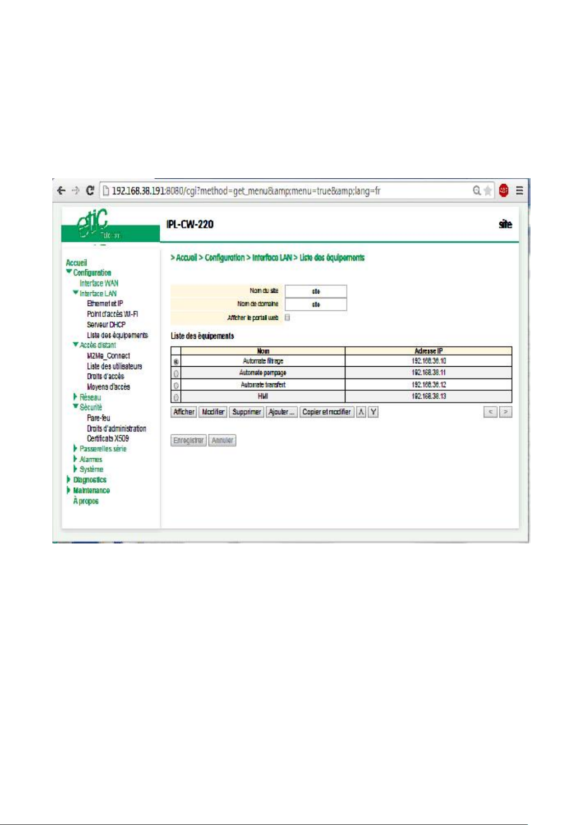
ADVANCED SET-UP
2.4 Device list set-up
To set-up the device list,
Select the Set-up > LAN interface > device list menu
To add a device to the list,
Click the « Add » button
Assign a name and an IP address to the device
Remark : it is possible to enter a subnet and only a device.
Example : 192.168.38.8/29 = 192.168.38.8 to 192.168.38.15
Page 76 DOC_DEV_RAS_User guide_A Machine Access Box RAS
Page 77

ADVANCED SET-UP
2.5 DHCP server menu
The router RAS can behave like a DHCP server over the LAN interface.
In that case, a pool of addresses must be reserved ; the addresses of the pool are automatically distributed
to the devices of the LAN acting as DHCP clients.
The addresses of the LAN domain which do not belong to that pool can be allocated as fixed IP addresses to
particular devices.
Remark
Many Wi-Fi office devices like tablets or smartphones do not support a fixed IP address.
Select the Set-up > LAN interface > DHCP server
“IP address pool start” & “IP addresses pool end” parameters :
Enter the first and the last IP address reserved to the DHCP server.
« IP address » & « netsmask » parameters :
Enter the IP address assigned to the router over the LAN interface.
That IP address is also the IP address of the administration server of the router.
« Default gateway » parameter :
If another router is connected to the LAN network giving access to other networks, and acting as the default
gateway for the router RAS, enter the address of the router.
Machine Access Box RAS DOC_DEV_RAS_User guide_A Page 77
Page 78

ADVANCED SET-UP
M2Me_Connect connection set-up
The M2Me_Connect connection is a VPN set from the router RAS to the M2Me_Connect server.
The VPN can be transported in UDP or TCP.
Select the Set-up > Remote access > M2Me_Connect
« TCP port » & « UDP ports » parameters :
Enter the selected UDP and TCP ports the router will have to test to set the M2Me VPN.
The router RAS will try to set the M2Me connection successively with the selected UDP and TCP ports
beginning with UDP.
If a proxy server filters outgoing connections, unselect the No Proxy checkbox and enter the Proxy server
parameters :
the type of the proxy server (HTTP, SOCKS5)
the proxy IP address and port number
the type of required authentication (None, basic, NTLM) if the proxy is http
Test the M2Me connection
Pour commander la connexion du routeur au service M2Me_Connect, cliquer le bouton « Connecter
maintenant ».
Pour vérifier que la connexion s’effectue normalement, sélectionner le menu « Diagnostic » puis « Etat
réseau » puis « M2Me ».
Lorsque la connexion aboutit, le message « Connecté » s’affiche dans le champ « Etat » ainsi que le N° de
port et le protocole utilisé.
Attention : Do not forget to copy the product key of the router RAS (ABOUT menu); it is used by the M2Me
software of the remote PC to set the connection to the router RAS.
Once the M2Me connection has een set, remote users must be registered in the user list and access rights
must be assigned to each of them.
Page 78 DOC_DEV_RAS_User guide_A Machine Access Box RAS
Page 79
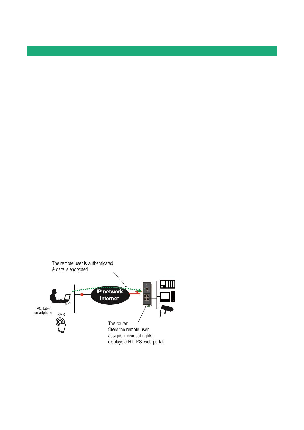
ADVANCED SET-UP
Remote access connection
Remark : Providing a secure remote access service requires three steps :
Step 1 : The remote connection set-up itself described in this paragraph.
Step 2 : The user list set-up described in the next paragraph.
Step 3 : The access rights definition described in the next paragraph.
4.1 Advantages of a remote access connection
Using a remote connection to access to a machine provides the following advantages :
Remote users identification
The remote user login and password are registered in the user list.
When he connects, the login and password of the remote user, and optionaly the certificate of his PC are
checked.
The certificate can be delivered by ETIC TELECOM or by another authority.
Selective access rights
Individual access rights can be assigned to each remote user according to his identity.
Transparent connection
Once the remote connection has been launched, the PC receives automatically an IP address of the network.
The user can access to each authorized device of the network.
Data encryption
Data is encrypted from end to end.
PC, Tablet, smartphone
The solutions provided by the ETIC router are suitable as well for Windows PCs or tablets or smartphones
(Androïd or IOS).
To set-up a remote connection,
Machine Access Box RAS DOC_DEV_RAS_User guide_A Page 79
Page 80
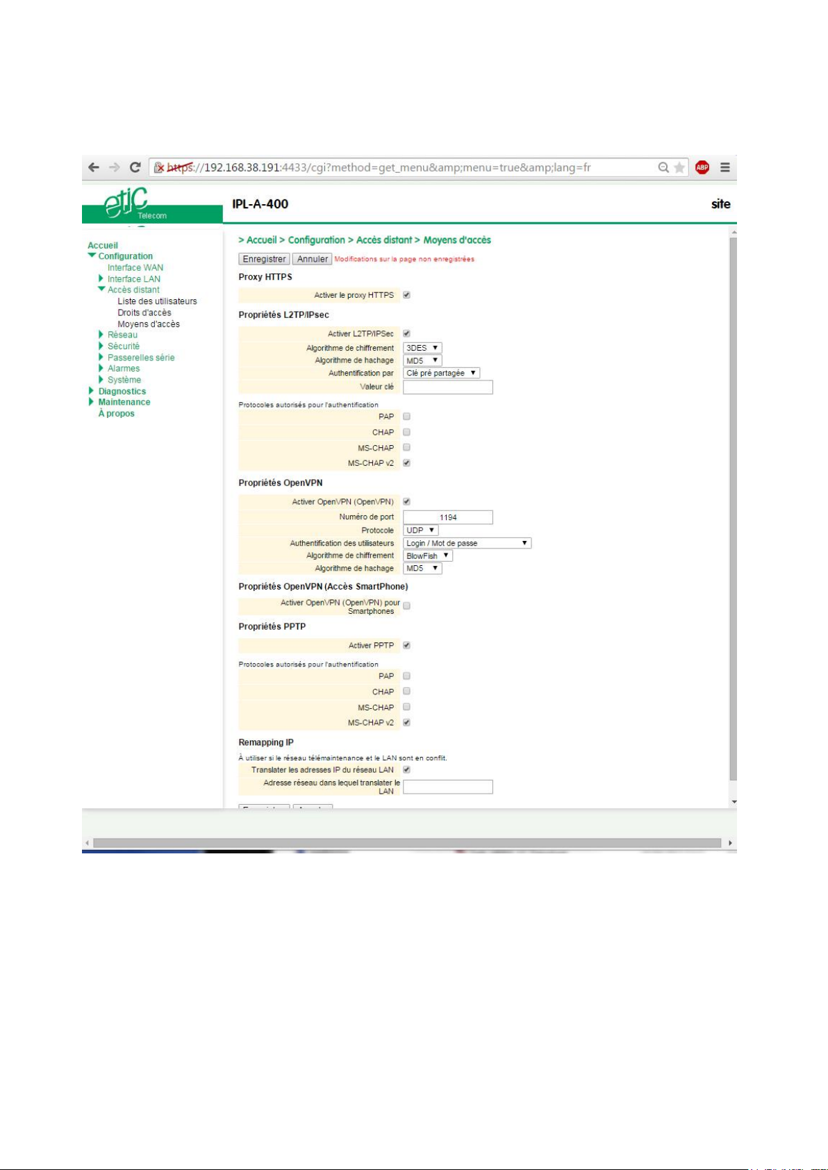
ADVANCED SET-UP
Select Set-up > Remote access > Remote access servers
Page 80 DOC_DEV_RAS_User guide_A Machine Access Box RAS
Page 81

ADVANCED SET-UP
Remote user
Identification
Authentication
Encryption
OpenVPN
Login
PWD
Optionally a certificate
Yes
PPTP
Login
PWD
Yes
L2TP/IPSec
Login
PWD and
Preshared Key or certificate
Yes
HTTPS
Login
PWD
Yes
4.2 Types of remote access connections
Four types of remote access connections can be set-up :
OpenVPN.,
PPTP,
L2TP/IPSec,
HTTPS.
That four types of connection can be implemented in PCs, tablets or smartphones.
They can be active at the same time.
The HTTPS connection is mainly dedicated to secure remote access to HTML pages embedded in
supervision PCs, HMIs, or PLCs for instance;
When a remote user sets a remote user connection, whatever type, his identity is checked (Login / PWD).
Machine Access Box RAS DOC_DEV_RAS_User guide_A Page 81
Page 82
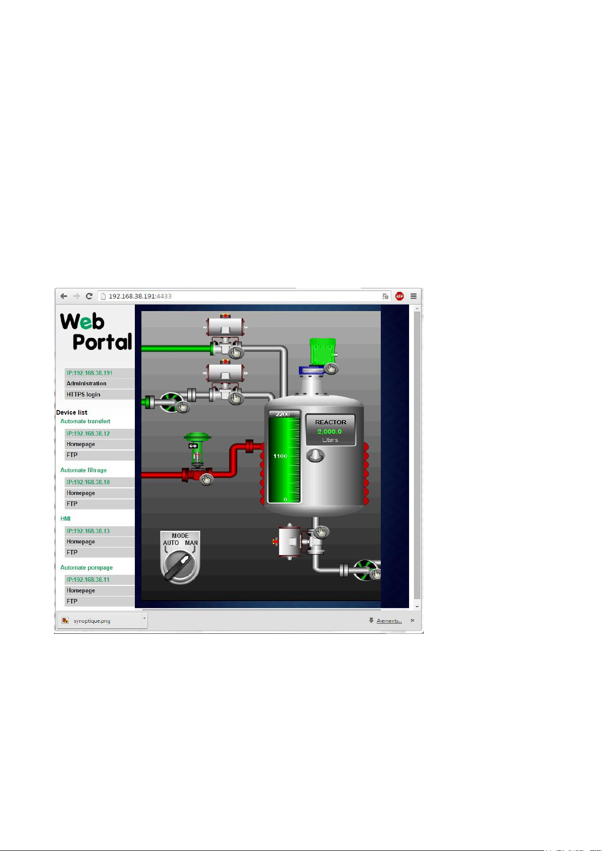
ADVANCED SET-UP
4.3 HTTPS connection and portal for smartphones, tablets or PCs
4.3.1 Overview
The ETIC router can behave like a HTTPS server for remote users.
In addition, the HTTPS server can behave like a HTTPS to HTTP gateway to give a secure remote access to
HTML / HHTP pages embedded in devices.
It means that a simple HTML / HTTP unsecure server can be used remotely through the internet in a safe way.
When a remote user connects to the ETIC router using an HTTPS secure connection, the portal displays the
list of the html servers to which he has the right to access.
That list can include as well HTTPS native servers or HTTP unsecured server.
The remote user just has to select one server in the list.
Page 82 DOC_DEV_RAS_User guide_A Machine Access Box RAS
Page 83

ADVANCED SET-UP
From the Internet
From the LAN
HTTPS web portal
https:// Internet IP address
LAN IP address
Administration web server
https://Internet IP address: 4433
LAN IP address
or https://adr. IP Internet : 4433
4.3.2 Set-up
To enable the HTTPS portal through the LAN interface,
Select Set-up > Remote access > Remote access server
Select the «Enable the HTTPS proxy » menu
To give access to the HTTPS portal through the Internet (WAN),
Select Set-up > Security > Administration rights
Select the « Use HTTPS for set-up operation » checkbox
Important remark :
When the HTTPS portal is enabled, the access to the administration server and to the HTTPS portal from the
LAN or from the WAN are organised according to the table below :
4.3.3 Operation
To access to the HTTPS internet portal from the Internet,
Launch the browser
Enter : https:// « Internet IP address of the ETIC router»
Enter the login and password when the identification window is displayed.
The Web portal page displays the list of the web servers to which it is possible to connect according to the
user identity.
Machine Access Box RAS DOC_DEV_RAS_User guide_A Page 83
Page 84

ADVANCED SET-UP
4.4 OpenVPN remote user connection
The remote user can be authenticated with a password or with a password and a certificate.
The data is encrypted.
On the remote PC side, one can use a standard OpenVPN client or, if the PC is running Windows, the
M2Me_Secure software which is simple to install, set-up and use.
To set-up the OpenVPN connection,
Select the OpenVPN checkbox
« TCP port » & « UDP ports » parameters :
Select UDP or TCP and the port number.
Attention :
If OpenVPN VPNs between routers must also be set, the selected protocol (TCP or UDP) and port number of
the OpenVPN VPN must different from the protocol and port number of the remote user connection.
«Remote users authentification» parameter :
Select the “Login / password” value or the “Login/password & certificate” value if the certificate of he remote
PC must be checked.
In that case, the certificate of the remote PC must be stored in the ETIC router (see the table at the top of the
page).
« Encryption Algorithm» & « Message digest allgorithm» :
Leave the default values Blowfish et MD5.
4.5 OpenVPN connection for smartphones
It is possible to differentiate a remote user connection intended for PCs and another remote user connection
intended for smartphones.
The protocol (TCP or UDP) or the port number of the smartphone connection must be different from the
ones intended for PCs.
Select the smartphone remote user connection
« TCP port » & « UDP ports » parameters :
Select UDP or TCP and the port number.
Attention :
If VPN between routers must also be set, the selected protocol and port number of the OpenVPN VPN must
different from the protocol and port number of the remote user connection.
«Remote users authentification» parameter :
Select the “Login / password” value or the “Login/password & certificate” value if the certificate of he remote
PC must be checked.
In that case, the certificate of the remote PC must be stored in the ETIC router (see the table at the top of the
page).
Page 84 DOC_DEV_RAS_User guide_A Machine Access Box RAS
Page 85

ADVANCED SET-UP
« Encryption Algorithm» & « Message digest allgorithm» :
Leave the default values Blowfish et MD5.
4.6 PPTP connection
Select the PPTP checkbox.
If the remote are PC running Windows, select only the MS-CHAP V2 checkbox.
4.7 L2TP / IPSec connection
Select the L2TP/ IPSec checkbox.
«Remote users authentification» parameter :
Select the “Login / password” value or the “Login/password & certificate” value if the certificate of the
remote PC must be checked.
In that case, the certificate of the remote PC must be stored in the ETIC router (see the table at the top of the
User list page).
« Encryption Algorithm» & « Message digest allgorithm» parameters :
Leave the default values 3DES & MD5.
« Authentication method» parameter :
Select “preshared key” or “certificate”.
If the choice “Certificate” is selected, the remote PCs certificates must be stored in the ETIC router (User list
menu).
Machine Access Box RAS DOC_DEV_RAS_User guide_A Page 85
Page 86
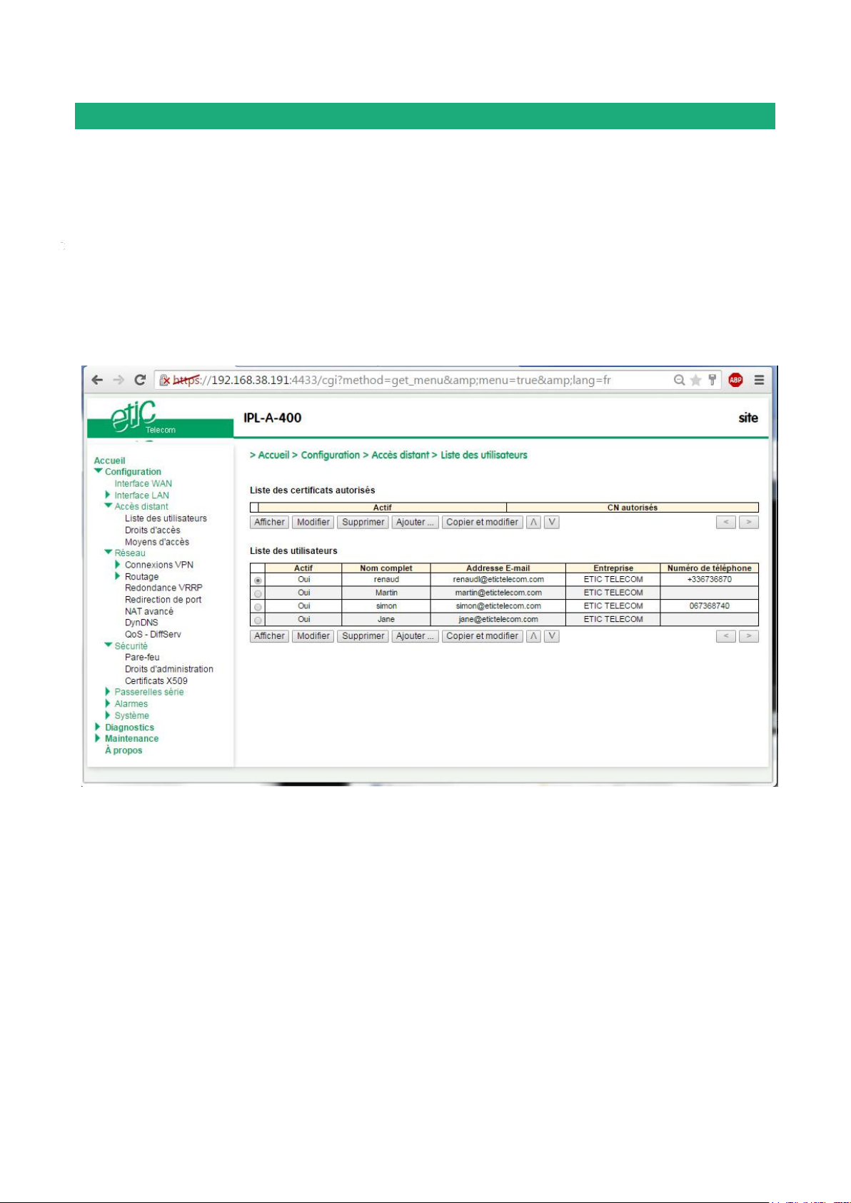
ADVANCED SET-UP
User list
It is necessary to register at least one remote use in the user list.
The users list is able to register 25 authorised remote users forms.
Each user form stores the identity of the user (Login and password), his email address to send alarm emails
and his mobile telephone number to send alarm SMS to him.
To display the user list,
select the Set-up> Remote access> User list menu
Remark : Coming from factory, the user list is empty.
Page 86 DOC_DEV_RAS_User guide_A Machine Access Box RAS
Page 87
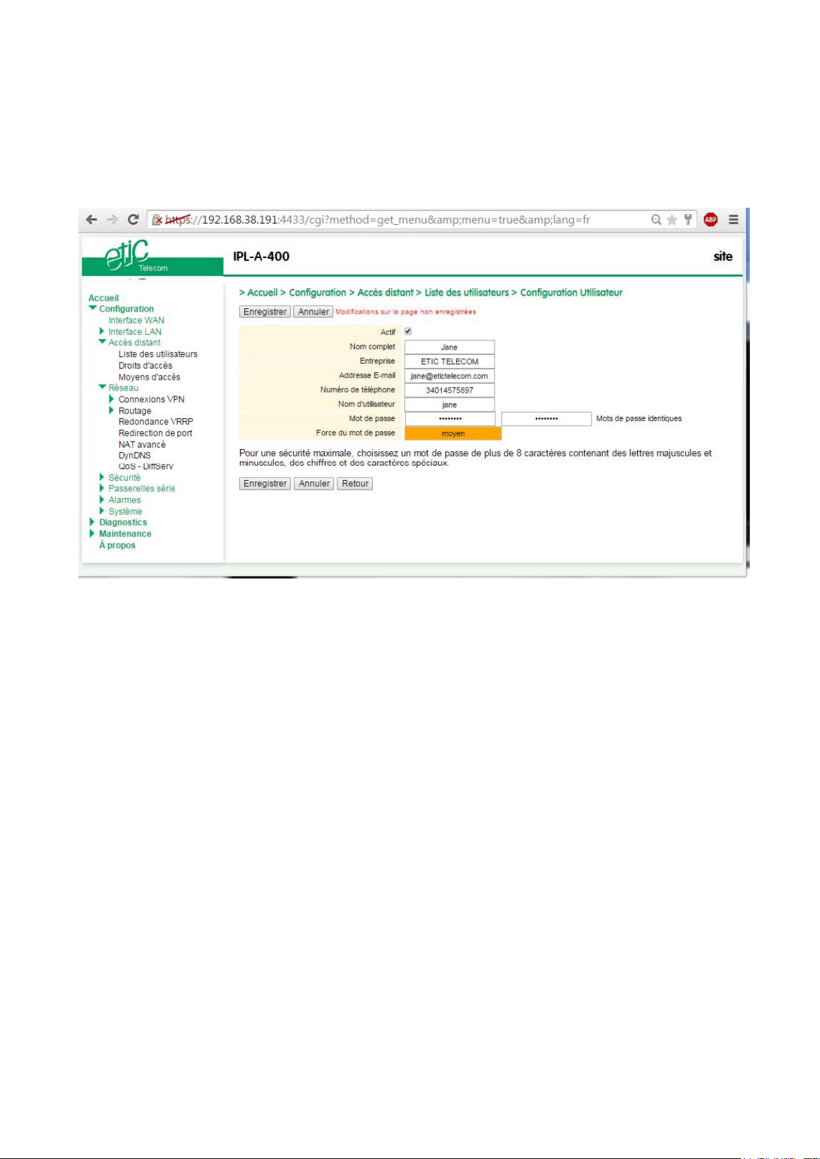
To register a remote user in the user list,
Click the « ADD » button located under the user list.
ADVANCED SET-UP
Enter the identity of the user (Login and password), his email address to send alarm emails.
Machine Access Box RAS DOC_DEV_RAS_User guide_A Page 87
Page 88
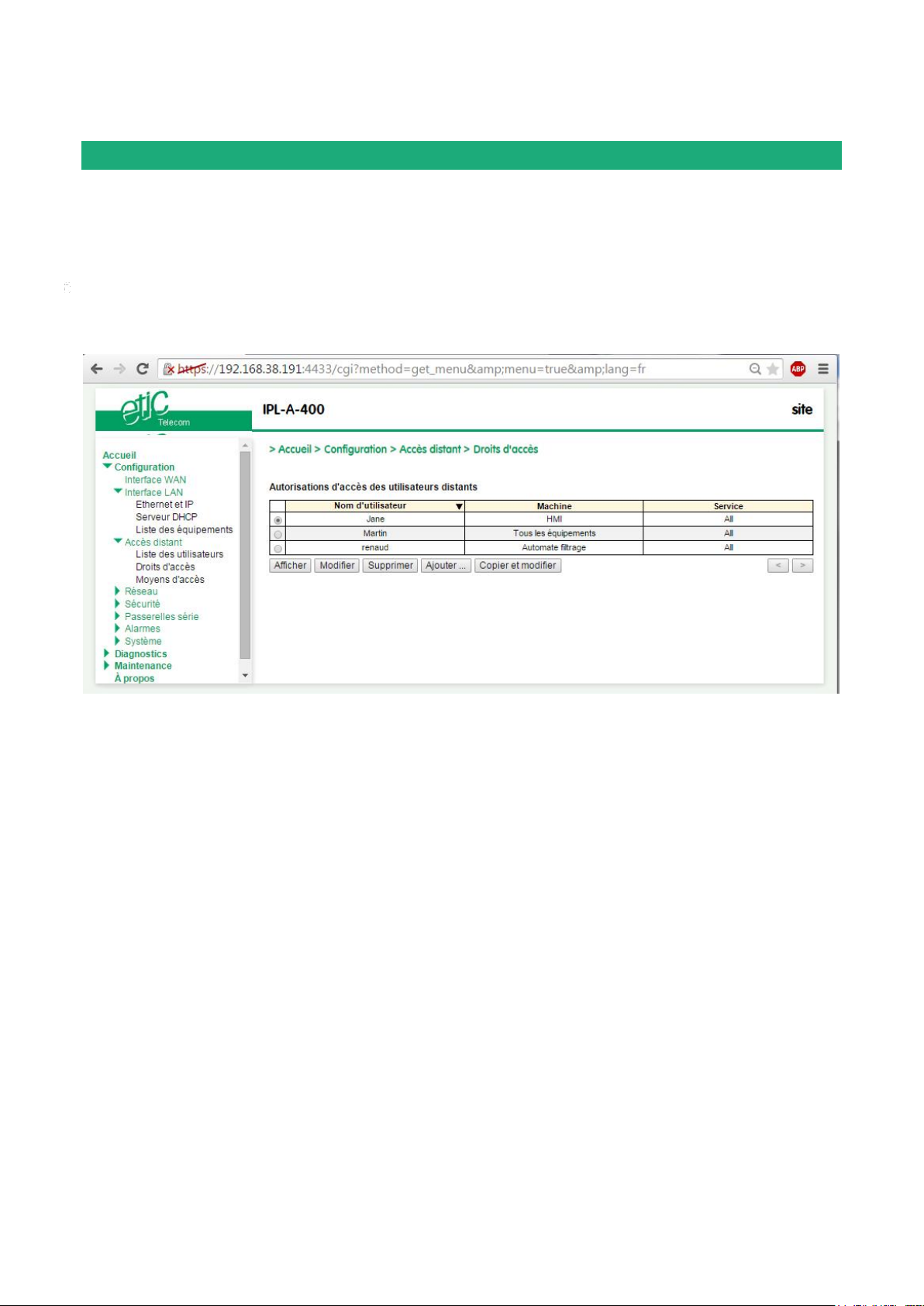
ADVANCED SET-UP
Assigning rights to remote users
Individual access rights to the network can be assigned to each user.
The list of devices of the LAN network must have been registered previously (LAN interface menu).
To grant access rights to a remote user,
Select the set-up, remote access, access rights menu.
Click the « Add » button.
Select a remote user in the list.
Select a device in the list to authorise the remote user to access to that device.
Remark : A device ca be a subnet or an IP address (refer to the Set-up> LAN interface > Device list).
Page 88 DOC_DEV_RAS_User guide_A Machine Access Box RAS
Page 89

ADVANCED SET-UP
IPSec VPNs set-up
7.1 Overview
An IPSec VPN tunnel allows to connect two networks in a safe and transparent way : Each device of the first
network can exchange data with any device of the other network.
25 IPSec connections can be set by one ETIC router.
Glossary
The router which initiates the IPSec VPN is called the initiator; the other one is called the responder.
Preshared key authentication
Only one preshared key can be stored in one ETIC router; it is used by all the VPNs and also by the
L2TP/IPSec remote user connection.
Certificate authentication
The authentication of the two participants to the VPN connection can also be carried-out with certificates.
Coming from factory , a certificate produced by ETIC TELECOM is registered in the ETIC router.
Other kinds of X509 certificates can be added. (see the Set-up>Security>X509 certificate).
The certificate used by each participant to the VPN must be delivered by the same authority.
Setting-up an IPSec tunnel in the case where the source IP address is modified along the way from the
initiator to the responder router.
To provide a strong mutual authentication, each router checks the source IP address of the frames it
receives is the authentical IP address.
It is why, the IPSec tunnel requires a particular setup when the IP address of the initiator or the responder is
not fixed and / or when intermediate routers replace the source IP address by their own address (NAT).
It is what happens, in particular, in the case of cellular networks.
Two set-up solutions are possible :
Solution 1 : Use a certificate for authentication instead of a preshared key
Solution 2 : if the preshared key authentication method is used, an IKE code (IKE ID) needs to be assigned to
each router. See the IPSec set-up paragraph hereafter.
Machine Access Box RAS DOC_DEV_RAS_User guide_A Page 89
Page 90
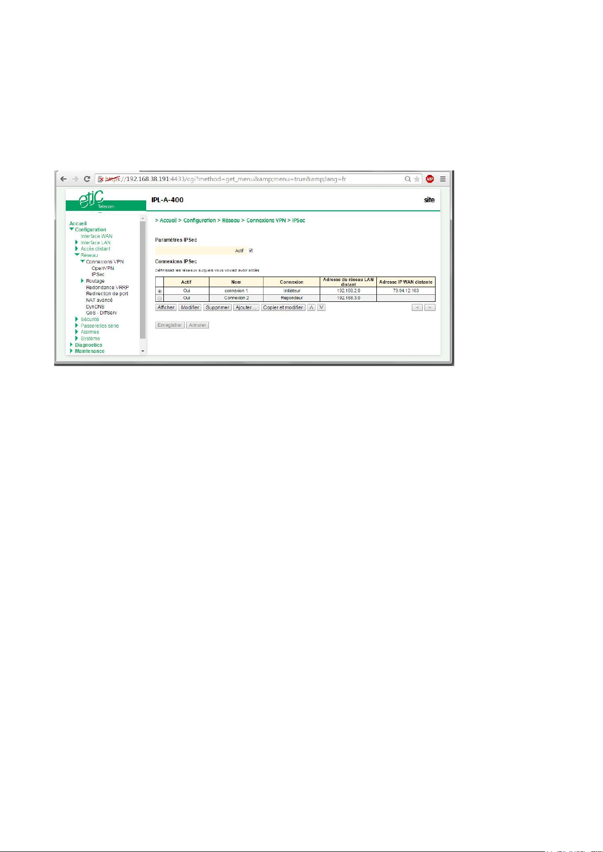
ADVANCED SET-UP
7.2 IPSec VPN connection set-up
Select the Set-up> Network > IPSec VPN menu
The IPSec VPN home page is displayed.
Page 90 DOC_DEV_RAS_User guide_A Machine Access Box RAS
Page 91
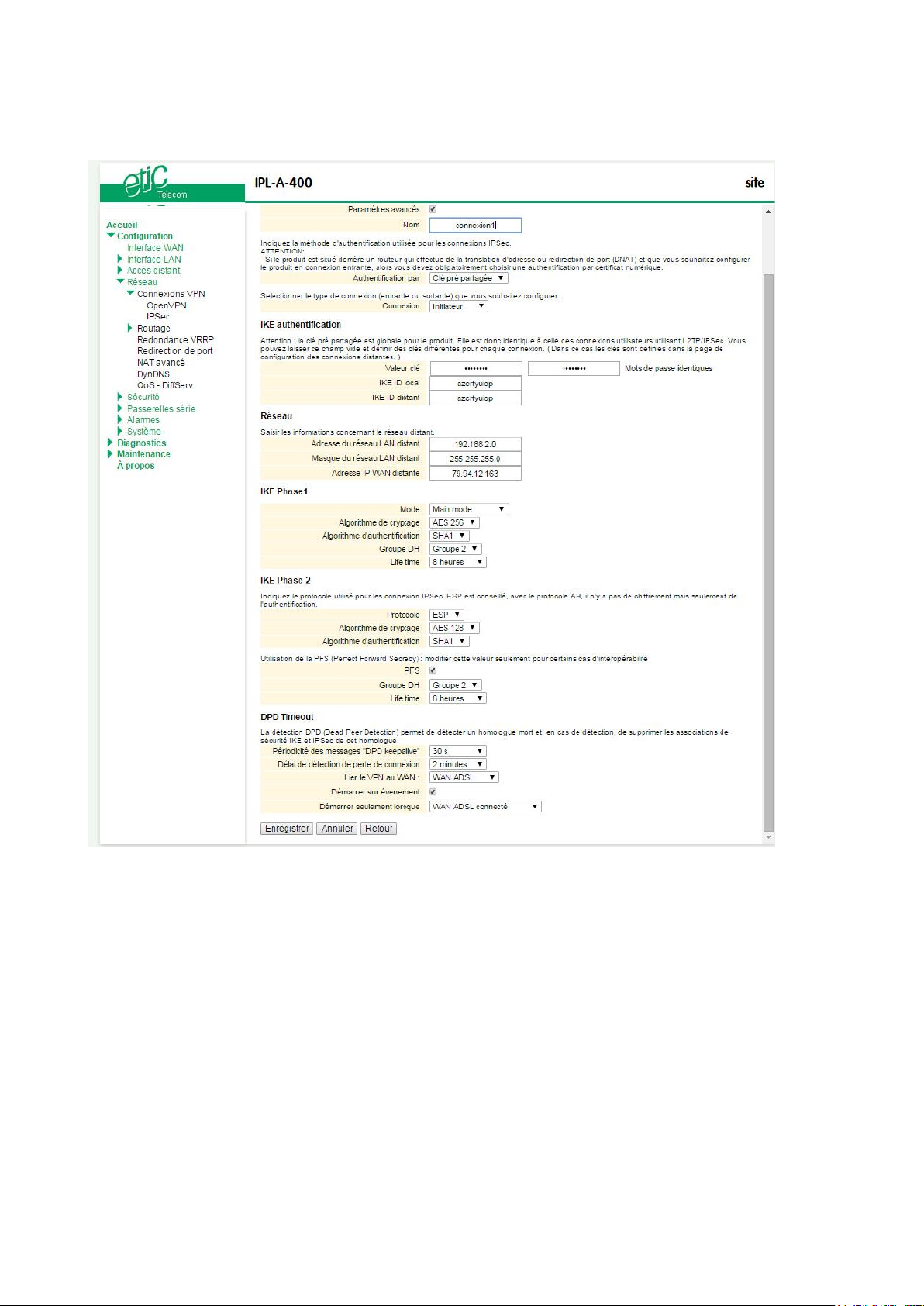
ADVANCED SET-UP
To add an IPSec VPN connection, click « Add». The set-up page of the new VPN connection is displayed.
Machine Access Box RAS DOC_DEV_RAS_User guide_A Page 91
Page 92
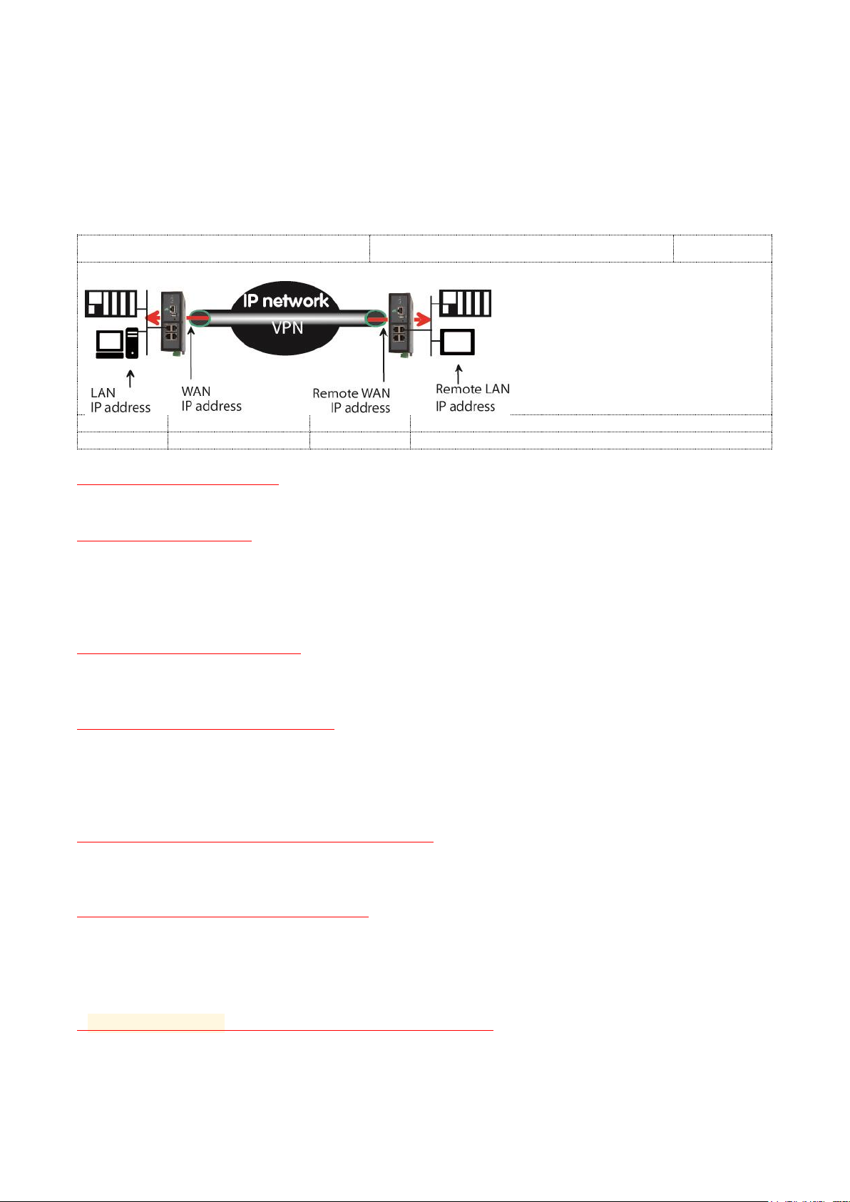
ADVANCED SET-UP
Current router
Remote router
192.168.1.0
10.10.10.7
10.10.10.100
192.168.2.0
255.255.255.0
255.255.255.0
Select the Enable checkbox.
Select the Advanced parameters checkbox if a preshared key is used and if intermediate routers translate
the source P address.
Assign a name to the connection.
The different IP addresses used during the set-up are described by the drawing below.
« Authentification » parameter :
Select preshared key or certificate.
« Connection » parameter :
Select Initiator if the current router is supposed to initiate the VPN.
Authentication section– Case 1 : Use of a certificate
Remark : Both certificates must be delivered by the same authority
« My SubjectAlt name » parameter:
Enter the 'SubjectAltName' value of the active certificate of the current router.
If the active certificate is an ETIC TELECOM certificate, that field is the email field.
Remote « SubjectAlt name » parameter :
Enter the 'SubjectAltName' value of the active certificate of the remote router.
If the active certificate is an ETIC TELECOM certificate, that field is the email field.
Authentication section– Case 2 : Use of a preshared key
« Preshared key » and « Passwords match » parameter :
Enter and confirm the preshared key.
The maximum length of the key is 40 characters.
« Local IKE ID» & « Peer IKE ID » parameters :
That identifiers make possible to set a preshared key VPN even if intermediate routers modifiy the source IP
address.
The router receiving an IP frame checks the IKE ID of the remote router in place of its source IP address.
Network section
« Remote LAN IP address » & « Remote LAN Netmask” parameters :
Enter the IP address and netmask of the remote LAN network
192.168.2.0 & 255.255.255.0 of the drawing below
Page 92 DOC_DEV_RAS_User guide_A Machine Access Box RAS
Page 93

ADVANCED SET-UP
« Remote WAN IP address » & « Remote WAN Netmask” parameters (initiator only):
Enter the WAN IP address of the remote router
Remark :
This address is the address of the router towards which the VPN must be set.
IKE phase 1 section
IKE phase 1 performs mutual authentication between the two parties with the end result of having shared
secret keys.
« Exchange Mode» parameter :
Select Main or Agressive.
The « Agressive » mode is simpler and faster than the « Main » mode.
«Encryption algorithm» parameter :
Recommended value : Auto
«Authentification algorithm» parameter :
The « Auto » choice is advised.
SHA1 provides a better security than MD5.
«DH group» parameter (only if the advanced parameters option has been selected) :
Recommended value : group 2.
The same value must be selected for the two routers.
«Life-time» parameter (only if the advanced parameters option has been selected) :
Enter the life-time of the IKE security association.
After that period of time, the IKE step 1 is carried-out again.
Machine Access Box RAS DOC_DEV_RAS_User guide_A Page 93
Page 94

ADVANCED SET-UP
IKE phase 2 Section
The purpose of IKE phase two is to negotiate the IPSec parameters (general parameters, encryption, SA lifetime…).
The result of the IKE phase 2 is the encrypted tunnel between the two routers.
«Protocol » parameter :
This parameter enables to set-up the IPSec transport protocol.
AH insures authentication only but does not encrypt the transported data.
ESP ensures routers authentication and data encryption.
ESP will be preferred.
«Data encryption algorithm » parameter :
Recommended value : AES
«Authentication algorithm» parameter :
SHA1 provides a better security than MD5.
«PFS» checkbox :
With PFS disabled, initial keying material is created during the key exchange in phase-1 of the IKE
negotiation. In phase-2 of the IKE negotiation, encryption and authentication session keys will be extracted
from this initial keying material. By using PFS, Perfect Forwarding Secrecy, completely new keying material
will always be created upon re-key. Should one key be compromised, no other key can be derived using that
information.
«DH group» parameter (only if the PFS option is enabled) :
Recommended value: Group 2.
«Life-time» parameter (only if the PFS option is enabled) :
Enter the phase 2 key life-time.
DPD section
DPD Keep-alive period” parameter : :
A DPD is a message sent periodically by each end-point to the other one to make sure that the VPN must be
left active.
This parameters sets the amount of time (in seconds) between two of these requests.
“Connection death time-out” parameter :
This parameter defines the maximum amount of time (in seconds) a VPN connection will stay established if
no traffic or no DPD keep-alive message are received from the remote point.
Page 94 DOC_DEV_RAS_User guide_A Machine Access Box RAS
Page 95
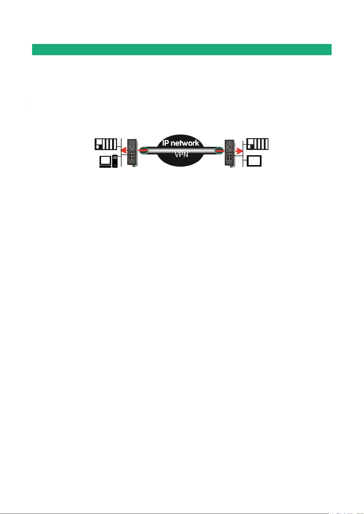
ADVANCED SET-UP
The router which initiates the connection is
called the VPN client
The connection is an outgoing connection
The router which receives the connection is
called the VPN server
The connection is an ingoing connection
OpenVPN type VPN connection
8.1 Overview
An OpenVPN VPN tunnel allows to connect two networks in a safe and transparent way : Each device of the
first network can exchange data with any device of the other network.
25 OpenVPN connections can be set by one ETIC router.
Glossary
The router which initiates the OpenVPN VPN is called the VPN client the other one is called the VPN server.
Login and password authentication
Each OpenVPN connection can be authentified using the Login & password of the VPN client.
Certificate authentication
The authentication of the two participants to the VPN connection can also be carried-out using certificates
in addition to a Login and password.
Coming from factory , a certificate produced by ETIC TELECOM is registered in the ETIC router.
Other kinds of X509 certificates can be added. (see the Set-up>Security>X509 certificate).
The certificate used by each participant to the VPN must be delivered by the same authority.
NAT translation insensitivity
While IPSEC is sensitive to address translation of the source IP address by intermediate routers, OpenVPN is
not.
The reasons is the source IP address is not checked by OpenVPN to authenticate the remote router; Open
VPN authenticates the remote router with a Login password and certificate.
That characteristic makes OpenVPN very easy to implement in many situations and in particular when a
cellular router is used.
Implementation easiness
The transport level of OpenVPN is TCP or UDP; the port number can be selected
That characteristic makes OpenVPN very easy and reliable to implement in many situations and in particular
when a cellular router is used.
Machine Access Box RAS DOC_DEV_RAS_User guide_A Page 95
Page 96
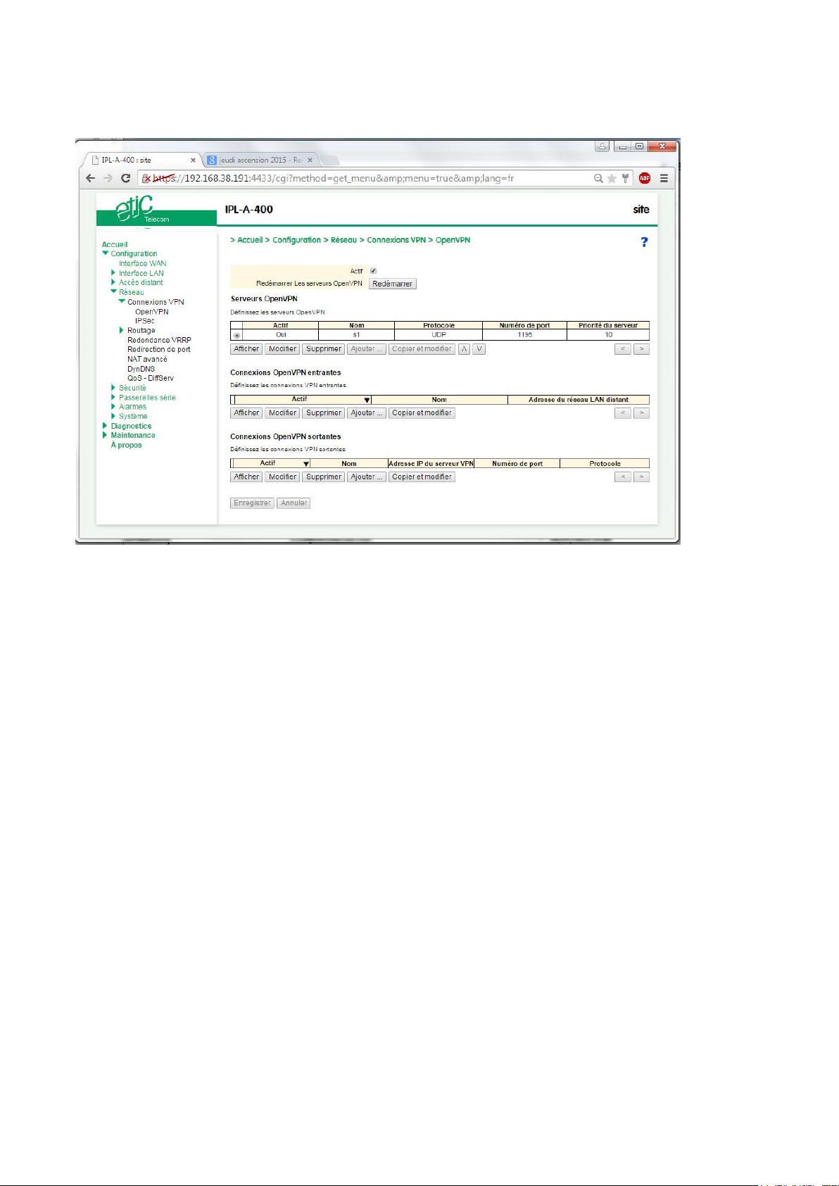
ADVANCED SET-UP
Page 96 DOC_DEV_RAS_User guide_A Machine Access Box RAS
Page 97
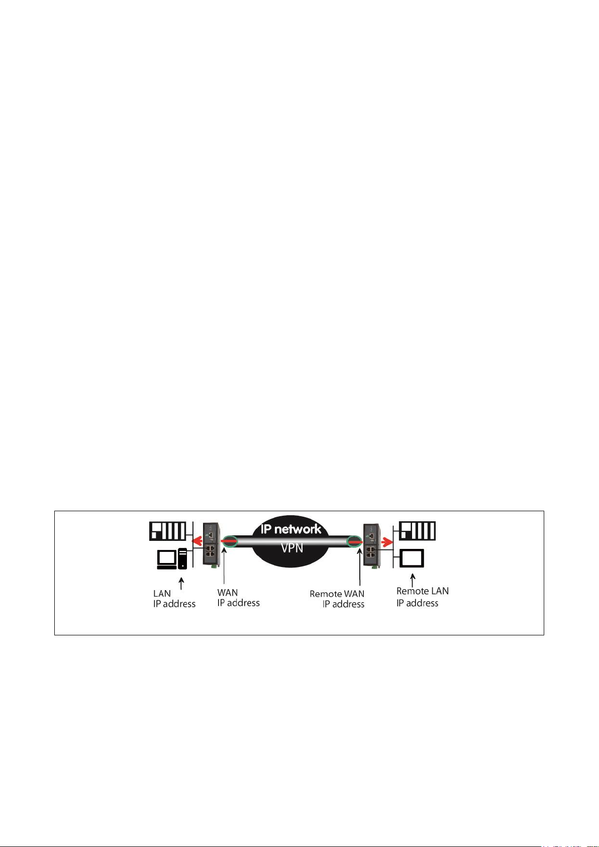
ADVANCED SET-UP
Current router
Remote router
8.1.1 Set-up principles
VPN server set-up
If the ETIC router behaves like a VPN server, it means that the ETIC router has to receive at least one ingoing
connection, the set-up has to be carried-out in two steps :
Step 1 : Configuration of the parameters of the OpenVPN server.
Only one server can be set-up.
Step 2 : Configuration of the ingoing, and possibly outgoing, connections.
The VPN server is unique; it can accept up to 25 ingoing connections from VPN clients.
VPN client set-up
If the ETIC router behaves only like a VPN client, the set-up consists only of configuring the outgoing
connection (one or several).
Set-up rules
Common parameters
The following parameters are common for the server and for all the clients supposed to set a VPN to that
server :
Transport protocol (UDP or TCP) and port number.
Encryption algorithm (Blowfish, AES 256, AES192, AES128, 3DES).
Authentication (MD5, SHA1).
IP domains
The IP domain of the LAN and of the remote LAN must be different.
Example :
LAN network : 192.168.1.0 netmask 255.255.255.0
Remote LAN : 192.168.2.0 netmask 255.255.255.0
Machine Access Box RAS DOC_DEV_RAS_User guide_A Page 97
Page 98

ADVANCED SET-UP
8.2 OpenVPN server set-up
Select the « Add » button located just below the VPN server table
“Port number” & “protocol” parameters :
Select the port Nr and the type of level 3 protocol used to transport OpenVPN.
Attention : The port number value must be different from the one used by remote users.
“VPN network address” & “VPN network netmask” parameters :
The OpenVPN server router assigns automatically an IP address to the VPN client router.
That VPN IP address must not be confused with the WAN interface IP address.
Leave the default values 172.16..0 and 255.255.0.0
“Connection death time-out” parameter :
A control message (also called Keep-alive message) is sent periodically by the VPN server router to make
sure that the VPN must be left active.
This parameter defines the period of the control messages.
As a consequence, it sets the maximum amount of time a VPN connection will stay established before being
cleared if no response to the VPN control message is received from the remote router.
Remark :
The value of this parameter must be selected carefully ; If the VPN has been cleared, for any reason, the
router will wait during that period of time before lauching the VPN again.
“Packet retransmit time-out” parameter:
This parameters sets the amount of time (in seconds) the server will wait for the response to the keep-alive
control message before repeating it.
“Encryption algorithm” & “Authentication algorithm” parameter :
AES provides a better encryption than 3DES, and SHA-1 a better authentication than MD5.
« Priority » parameter :
Enter a an intermediate value : 100 for instance.
« Push local route to VPN clients » parameter :
If that checkbox is selected, the server broadcasts to the clients the route to the IP domain of its local
network.
Leave that checkbox selected.
«Push static routes to VPN clients » parameter :
If that checkbox is selected, the server broadcasts to the clients the static routes which have been set-up int
the VPN server.
Leave that checkbox selected.
Page 98 DOC_DEV_RAS_User guide_A Machine Access Box RAS
Page 99

ADVANCED SET-UP
«Push client routes » checkbox :
Two solutions exist to enable a device connected to a VPN client router to exchange data with another
device connected to another VPN client router.
The first one is to program a static route in both VPN client routers.
The second one is to select the “Push clients routes” option.
If that option is selected, the VPN server broadcast to all the VPN clients the route to each of them.
In that way, each device of the network can exchange data with each other device.
Programming static routes is not necessary.
If that option is not selected, a device connected to a VPN client ETIC router can exchange data with a
device connected to the LAN network of the VPN server, but not with a device connected to one other
VPN client ETIC router.
If it is necessary static routes must be programmed in both routers RAS.
st
« 1
specific route to push» & « 2nd specific route to push» parameters :
Thess parameters allow to broadcast specific routes from the VPN server to the clients.
Machine Access Box RAS DOC_DEV_RAS_User guide_A Page 99
Page 100
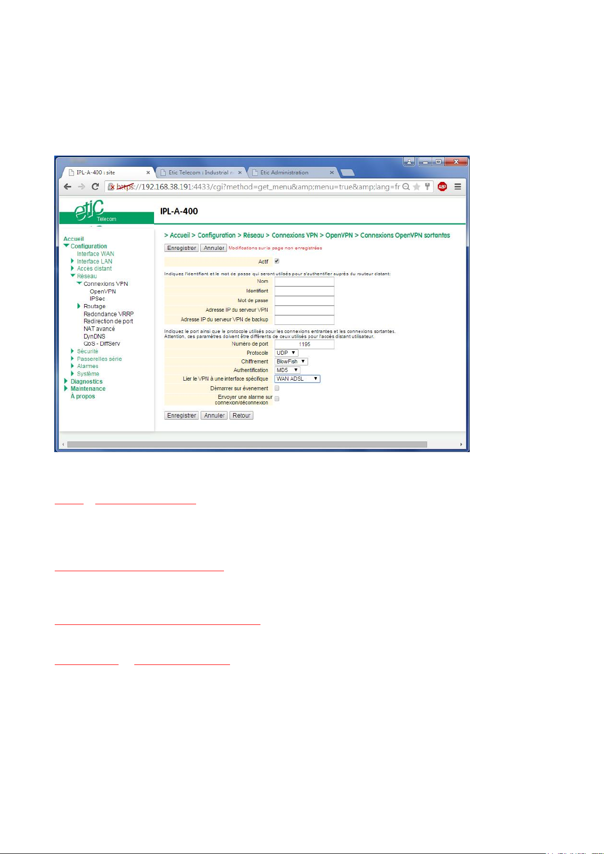
ADVANCED SET-UP
8.3 Setting up an outgoing connection
An outgoing connection is a connection initiated by the current router.
Select the « Add » button located just below the Outgoing connection table.
Select the « Enable » option and assign a name to the connection.
“Login & Password” parameter:
Enter the login and password, the router will have to use to authenticate.
Remark : That login & password must be registered in the ingoing connection.
« VPN server IP address» parameter :
Enter the IP address of the VPN server.
That address can be a public IP address or a domain name or a DynDNS or NoIP address.
« Backup VPN server IP address» parameter :
The client VPN ETIC router is able to set a backup VPN if the main VPN fails.
“Port number” & “protocol” parameters :
Select the port Nr and the type of level 3 protocol used to transport OpenVPN.
Attention : The port number value must be different from the one used by remote users.
Page 100 DOC_DEV_RAS_User guide_A Machine Access Box RAS
 Loading...