

Page 1
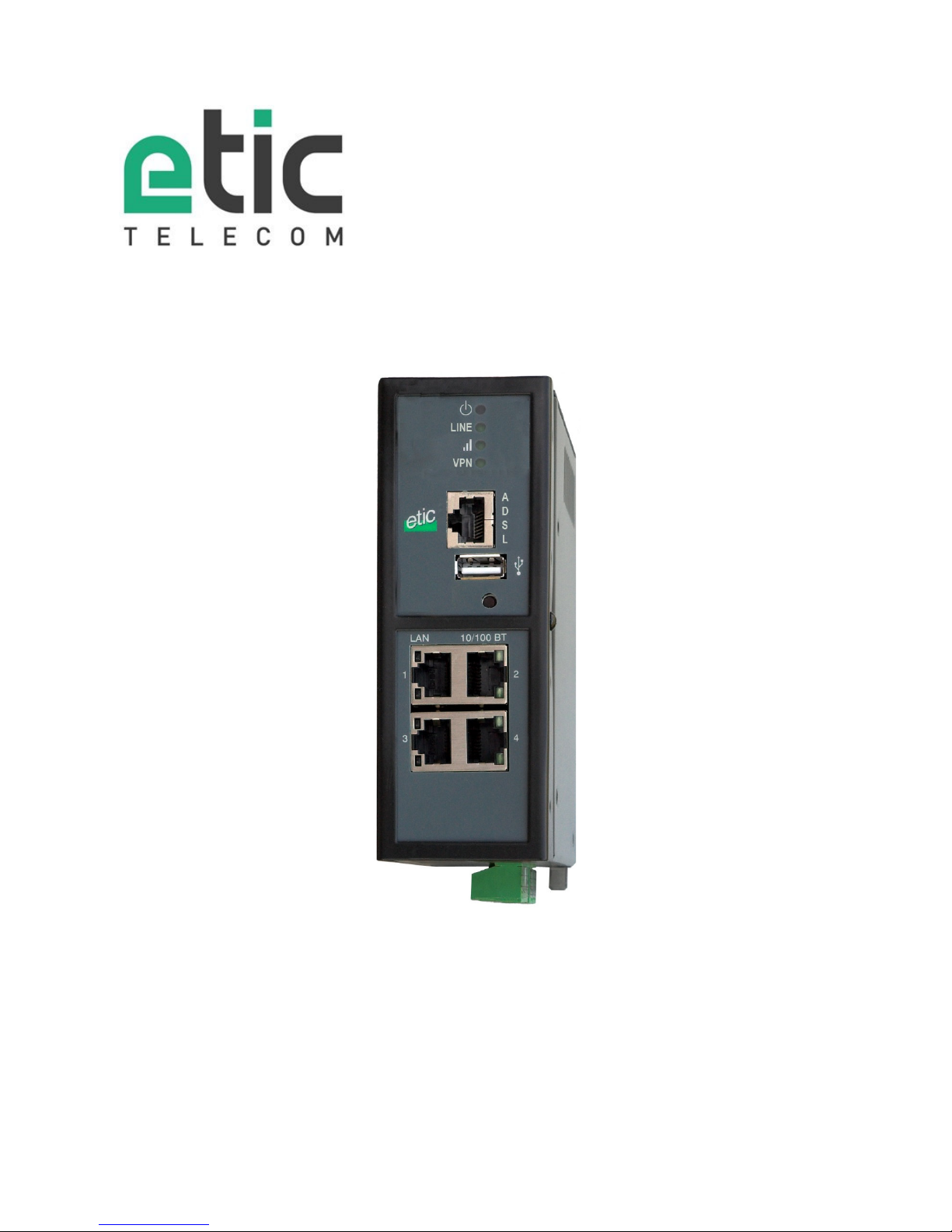
IPL-A
ADSL Router Firewall
_________________
USER GUIDE
Docume nt re ference : 9021 409-0 1
_________________
Page 2

The IPL-A ADSL router is manufactured by
ETIC TELECOM
13 Chemin du vieux chêne
38240 MEYLAN
FRANCE
TEL : + 33 4-76-04-20-00
Hotline : + 33 4-76-04-20-05
FAX : + 33 4-76-04-20-01
E-mail : [email protected]
web : www.etictelecom.com
Page 3

ADSL Router Firewall IPL-A User Guide 9021409-01
Page 3
CONTENT
OVERVIEW ....................................................................................................................... 5
1
Certificate of conformity .................................................................................. 5
2
Products identification .................................................................................... 6
3
Data-sheet ....................................................................................................... 8
4
Product Overview .......................................................................................... 10
4.1 Applications .............................................................................................. 10
4.2 Functions .................................................................................................. 11
4.3 Router interfaces & organisation ................................................................ 12
INSTALLATION .............................................................................................................. 13
1
Product description ....................................................................................... 13
1.1 Dimensions ............................................................................................... 13
1.2 Push-buttons ............................................................................................ 13
1.3 Connectors ................................................................................................ 13
1.4 IPL-A-400 or IPL-AW-400 (WiFi option) ..................................................... 17
1.5 IPL-A-220 or IPL-AW-220 (WiFi option) ..................................................... 18
1.6 IPL-A-230 or IPL-AW-230 (WiFi option) ..................................................... 19
1.7 IPL-A-260 or IPL-AW-260 (WiFi option) ..................................................... 20
1.8 IPL-A-261 or IPL-AW-261 (WiFi option) ..................................................... 21
2
Mounting the product on a Din rail ................................................................. 22
3
Cooling .......................................................................................................... 22
4
Supply voltage ............................................................................................... 23
5
Digital input and output ................................................................................. 23
6
RS232 ........................................................................................................... 23
7
RS485 connection (IPL-A-220 or IPL-AW-220) .............................................. 24
8
RS422 isolated interface (IPL-A-260 or IPL-AW-260) ................................... 25
9
RS485 isolated interface (IPL-A-261 or IPL-AW-261) .................................... 26
10
Connecting the router to the ADSL line .......................................................... 27
11
ADSL subscription ......................................................................................... 28
Page 4

CONTENT
Page 4
User Guide 9021409-01 ADSL Router Firewall IPL-A
PREPARING THE SETUP ................................................................................................ 29
1
First setup ..................................................................................................... 29
2
Protecting the access to the administration web server ................................. 29
3
HTTPS set-up modifications through the WAN interface ................................ 30
4
Recovering the factory LAN IP address .......................................................... 30
5
Restoring the factory set-up .......................................................................... 30
6
Saving or restoring a set of parameters ......................................................... 31
7
Configuration steps ....................................................................................... 32
DIAGNOSTIC .................................................................................................................. 34
1
Diagnostic ..................................................................................................... 34
1.1 Logs .......................................................................................................... 34
1.2 Network status .......................................................................................... 35
1.3 Serial gateways status ............................................................................... 36
1.4 « Ping » tool .............................................................................................. 36
1.5 « WiFi » scanner tool .................................................................................. 36
2
Firmware update ............................................................................................ 37
APPENDIX 1 : Wiring of the ADSL line surge arrester ...................................................... 39
Page 5

ADSL Router Firewall IPL-A User Guide 9021409-01
Page 5
OVERVIEW
Certificate of conformity
The manufacturer, ETIC Telecom – 13 chemin du vieux chêne – 38240 Meylan – France, Hereby declares
that the listed products
Type of device : ADSL Router IPL-A
Conforms to the Council Directive 1999/5/EC related to radio and telecommunication terminal equipment.
The harmonized standards to which the equipment complies are :
Standard Title
EN301489-1 Electromagnetic compatibility and Radio spectrum Matters :
Part 1 : General requirements
EN61000-6-2
Ed. 2001
Immunity :
EN60100-4-2 Electrostatic Discharge
EN60100-4-3 Radiated Immunity
EN60100-4-4 EFT/Burst Immunity
EN60100-4-5 Surge Immunity
EN60100-4-6 Conducted Immunity
EN61000-6-4
Ed 2001
Emission :
EN55022 radiated and conducted emission
EN60950 Security
EN50385 Human exposure to radio frequency fields exposure
Philippe DUCHESNE
Quality manager
5th January 2015
Page 6

OVERVIEW
Page 6
User Guide 9021409-01 ADSL Router Firewall IPL-A
Products identification
The present user guide describes the products listed hereafter.
ADSL router without WiFi
IPL-A-
400 220 230 260
261
ADSL 2+ & RE-ADSL
•
•
•
•
•
IP routing
•
•
•
•
•
Firewall SPI
•
•
•
•
•
IPSEC & OpenVPN VPNs (16 tunnels max.)
• • • • •
25 remote users RAS
PPTP / L2TP-IPSec / OpenVPN / HTTPS
•
•
•
•
•
HTTPS portal
•
•
•
•
•
Serial gateway (Raw TCP & UDP, Telnet, Modbus,
Unitelway)
-
•
•
•
Ethernet 10 / 100 BT
4
2 2 2
2
RS232 -
1
2 -
-
RS485 - 1
-
-
-
RS422 isolated - -
- 1 -
RS485 isolated - -
- - 1
USB
1 1
1 1 1
NAT
•
•
•
•
•
Port forwarding
•
•
•
•
•
SNMP
•
•
•
•
•
DNS
•
•
•
•
•
DHCP server on the LAN inteface
•
•
•
•
•
Digital input for alarm email
1
1
1
1
1
HTTPS / HTML / SSH configuration
•
•
•
•
•
Page 7

OVERVIEW
ADSL router with WiFi interface
IPL-AW-
400 220 230 260
261
ADSL 2+ & RE-ADSL
•
•
•
•
•
IP routing
•
•
•
•
•
WiFi 2.4 & 5 GHz Client or Access point
•
•
•
•
•
Firewall SPI
•
•
•
•
•
IPSEC & OpenVPN VPNs (16 tunnels max.)
• • • • •
25 remote users RAS
PPTP / L2TP-IPSec / OpenVPN / HTTPS
•
•
•
•
•
HTTPS portal
•
•
•
•
•
Serial gateway (Raw TCP & UDP, Telnet, Modbus,
Unitelway)
_
•
•
•
•
Ethernet 10 / 100 BT
4
2 2 2
2
RS232 _
1
2 _
_
RS485 _ 1
_
_
_
RS422 isolated _ _
_ 1 _
RS485 isolated _ _
_ _ 1
USB
1 1
1 1 1
NAT
•
•
•
•
•
Port forwarding
•
•
•
•
•
SNMP
•
•
•
•
•
DNS
•
•
•
•
•
DHCP server on the LAN inteface
•
•
•
•
•
Digital input for alarm email
1
1
1
1
1
HTTPS / HTML / SSH configuration
•
•
•
•
•
Option Référence
Service de connexion M2Me_Connect M2Me pack initial
Page 8
OVERVIEW
Page 8
User Guide 9021409-01 ADSL Router Firewall IPL-A
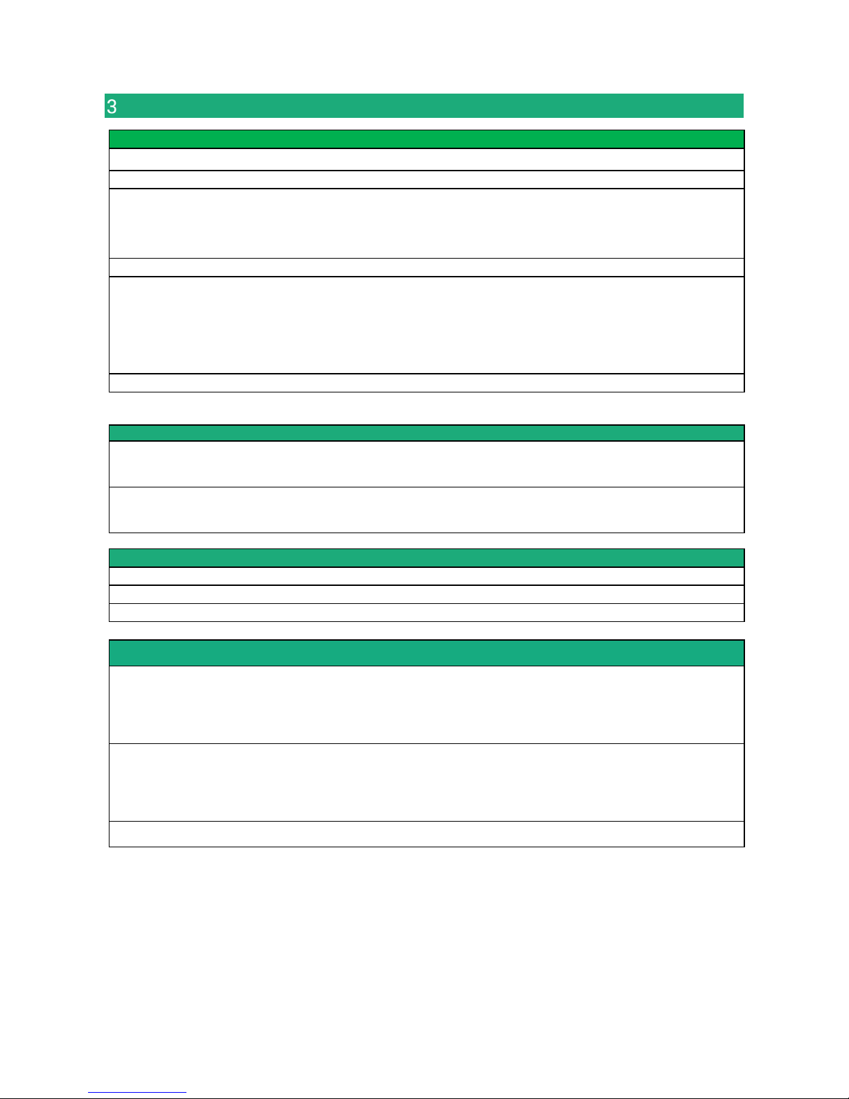
Data-sheet
General characteristics
Dimensions 137 x 48 x 116 mm (h, l, p)
Electrical safety EN 60950- UL 1950
EMC
ESD : EN61000-4-2 : Discharge 6 KV
RF field : EN61000-4-3 : 10V/m < 2 GHz
Fast transient : EN61000-4-4
Surge voltage : EN61000-4-5 : 4KV line / earth
RoHS 2002/95/CE (RoHS)
Supply voltage
IPL-A-400, IPL-AW-400 10 to 60 VDC
IPL-A-230, IPL-AW-230 10 to 60 VDC
IPL-A-260, IPL-AW-260 10 to 60 VDC
IPL-A-261, IPL-AW-261 10 to 60 VDC
IPL-A-220, IPL-AW-220 10 to 30 VDC
Operating T° -20°C / + 60°C Humidity 5 – 95 %
ADSL Connection
ADSL
ITU G992.5 (ADSL2+ et Reach Extended ADSL)
Up to 2.4 Mbit/s downstream
Up to 1 Mbit/s upstream
Encapsulation
PPPo Ethernet or PPPo ATM
EoA : Ethernet over ATM RFC2684 Bridged
IPoA : Routed IP over ATM, RFC2684 Routed
WiFI
Type 2.4 & 5 GHz
RF connector R-SMA female
WiFi transmission 802.11 a/b/g/n
VPN & firewall
VPN
Client or server IPSEC or OpenVPN
Encryption AES256 3DES
Certificate X509 or preshared key
16 VPNs maximum of the same type (OpenVPN or IPSec)
Firewall
Stateful packet inspection (50 rules)
Deny of service filter
Source & destination IP address & port number filter
Remote users filter
Logs Date and time stamped logs
Page 9
OVERVIEW
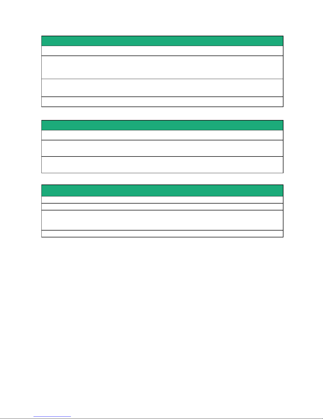
Remote access server (RAS)
User list 25 users
Connection
PPTP / L2TP-IPSec / Open VPN / HTTPS
Login & password
Certificate X509
M2Me
(option)
VPN Compliant with the M2Me_Secure VPN client
Compliant with the M2Me_Connect mediation service
Alarms 1 input : emails or SM (cellular models)
Serial interfaces
Data rate 1200 to 115200 kb/s parity N / E / O
Gateway
Raw TCP & UDP client & server - Modbus master & slave
Multicast - Telnet - Unitelway
USB
1 USB host port
PPP client over the usb interface
IP router
Ethernet 10/100 BT – 2 or 4 switched ports
IP router Static routes – RIP V2
IP address
translation
Source IP @ translation (NAT)
Destination IP @ translation (DNAT)
Port forwarding
DHCP LAN interface : Fixed IP @ or DHCP client or DHCP server
Page 10
OVERVIEW
Page 10
User Guide 9021409-01 ADSL Router Firewall IPL-A
Product Overview
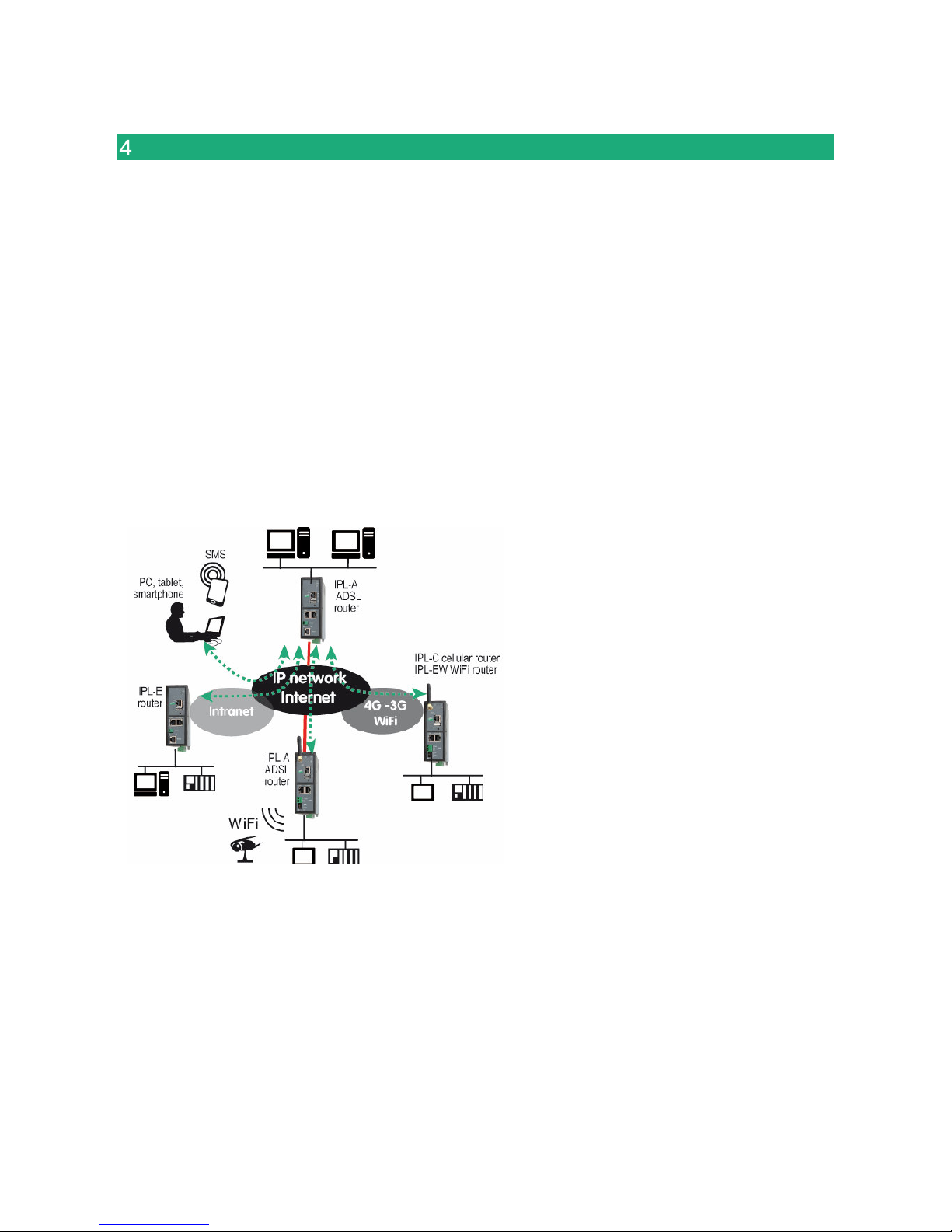
The IPL-A ADSL router is a security product.
It is designed to interconnect safely automated devices over the Internet.
The IPL-A is at the same time
• an IP router to route IP packets and set VPNs with other routers through the Internet.
• a remote access server (RAS) to provide a secure access to the LAN for remote users;
• a stateful inspection firewall to filter the IP traffic.
4.1 Applications
That features in the same product make the IPL-A a top level solution for remote SCADA systems and
remote maintenance through the Internet.
Page 11

OVERVIEW
4.2 Functions
IP router
The IPL-A router provides powerful, flexible and comprehensive solutions to route IP packets from one
network to other networks.
The solutions include static routes, RIP protocol and address translation (NAT, DNAT) and port forwarding.
IPSec & OpenVPN tunnels
The IPL-A features IPSec and OpenVPN tunnels to provide a high level of security and also compatibility with
existing devices.
Remote access server for PCs, tablets and smartphones
The IPL-A router can also behave like a remote access server.
If he is registered in the user list, a remote user can access to particular devices of a machine network
depending on his identity.
The new HTTPS portal make possible to access easily and safely to HMIs or PLCS web servers using a
tablet, a PC or a smartphone.
Firewall
The firewall protects against the sophisticated attacks coming from the Internet.
It is also able to filter IP frames between the WAN interface or any VPN interface on one hand, and the LAN
interface on the other hand.
VRRP redundancy
VRRP makes possible to usse two routers shaping a redundant solution.
DNS server
DNS makes it possible to assign Internet names to devices or organizations independently of their public IP
address.
The IPL-A router behaves like a DNS server for the devices connected to the LAN.
DHCP server
On the LAN interface, the IPL-A router can behave like a DHCP server.
WiFI interface
The IPL-A router provides optionaly a WiFi interface able to behave like a client or an access point.
Serial gateway
Optionally, the IPL-A router provides 1 or 2 serial RS232, RS485, RS422 interfaces.
Le serial gateway features the following modes :
Raw TCP client or server
Raw UDP
Telnet
Modbus master or slave
Unitelway
Page 12
OVERVIEW
Page 12
User Guide 9021409-01 ADSL Router Firewall IPL-A
4.3 Router interfaces & organisation
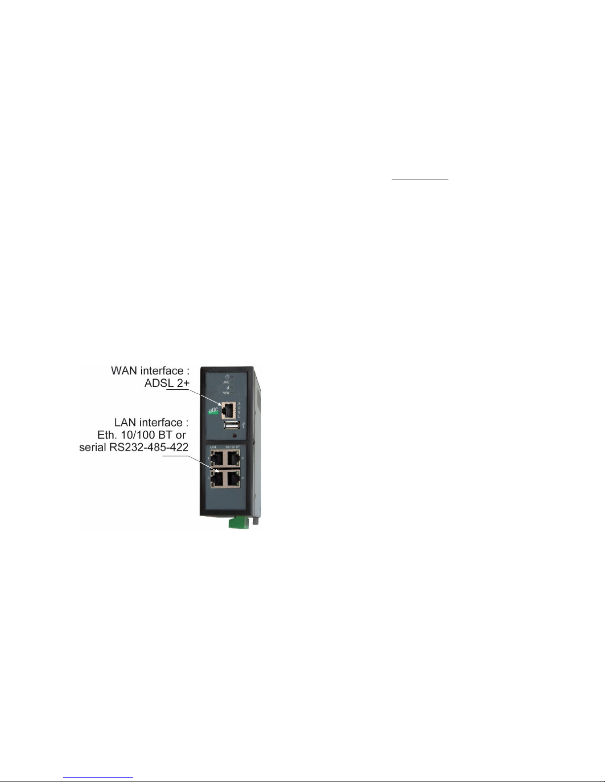
The IPL-A router provides two IP interfaces : The ADSL interface (WAN interface) to reach the Internet or a
private service and the LAN interface to connect the machine.
WAN interface :
The IPL-A router provides three WAN interfaces :
the ADSL interface is the main WAN interface; but the Ethernet interface of the RJ45 Nr1, or the WiFi
interface when it is used as a client, can be used as a WAN interface.
Only one interface can be selected as the WAN interface at the same time (ADSL, Ethernet port 1, WiFi).
LAN interface :
The LAN interface consists of Ethernet ports, optionally a WiFi interface when it is used as an access point
and serial interfaces.
Firewall
The firewall filters the IP frames between the ADSL WAN interface or any VPN interface on one hand, and
the LAN interface on the other hand.
Page 13
ADSL Router Firewall IPL-A User Guide 9021409-01
Page 13
INSTALLATION
Product description
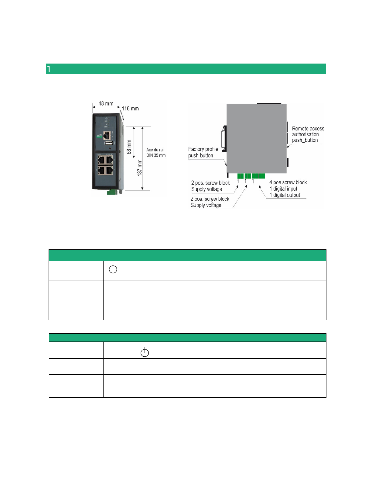
1.1 Dimensions
1.2 Push-buttons
Rear panel push-button
Pressing the rear
panel PB
led
Function
During operation Flashing red The default IP address 192.168.0.128 is selected
The current configuration remains active
During power-up Flashing red
The factory configuration and the default IP address
192.168.0.128 are selected.
The current configuration is deleted.
Front panel push-button
Pressing the front
panel PB
led
Function
During 5 seconds 3 flashes
The hotline of ETICTELECOM is authorised to connect remotely to
the router administration server within a 1 hour delay.
During 10 seconds 5 flashes A remote user is authorised to connect remotely to the router
administration server within a 10 mn delay without entering the
login r password
1.3 Connectors
Page 14
INSTALLATION
Page 14
User Guide 9021409-01 ADSL Router Firewall IPL-A
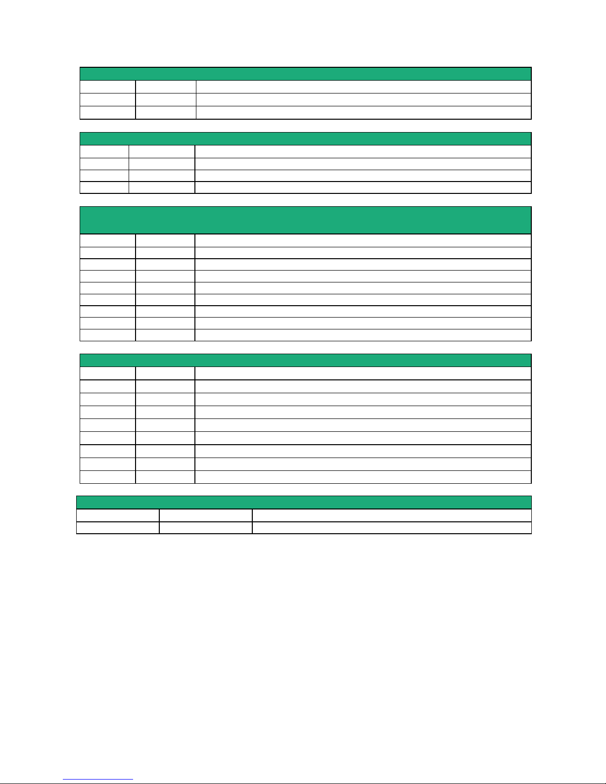
Supply voltage connector
Position Signal
Description
1 Power 1 + Supply voltage
2 Power 1 - 0V
Digital inputs & outputs
Position Signal
Description
1 0V O V
2 In Digital input
4 F
- Digital output
-
ADSL
RJ45 connector
Remark : An RJ11 cable can be connected to the RJ45 ADSL connector
Position Signal
Description
1 N.C. -
2 N.C. -
3 N.C. -
4 TIP Ligne ADSL
5 RING Ligne ADSL
6 N.C. -
7 N.C. -
8 N.C. -
RJ45 Ethernet)
Position Signal
Description
1
Tx +
Emission polarity +
2
Tx -
Emission polarity -
3
Rx +
Reception polarity +
4
N.C
-
5
N.C
-
6
Rx -
Reception polarity -
7
N.C.
-
8
N.C.
-
WiFi Antenna connector
Network Type
Description
WiFi RP-SMA female
Page 15
INSTALLATION
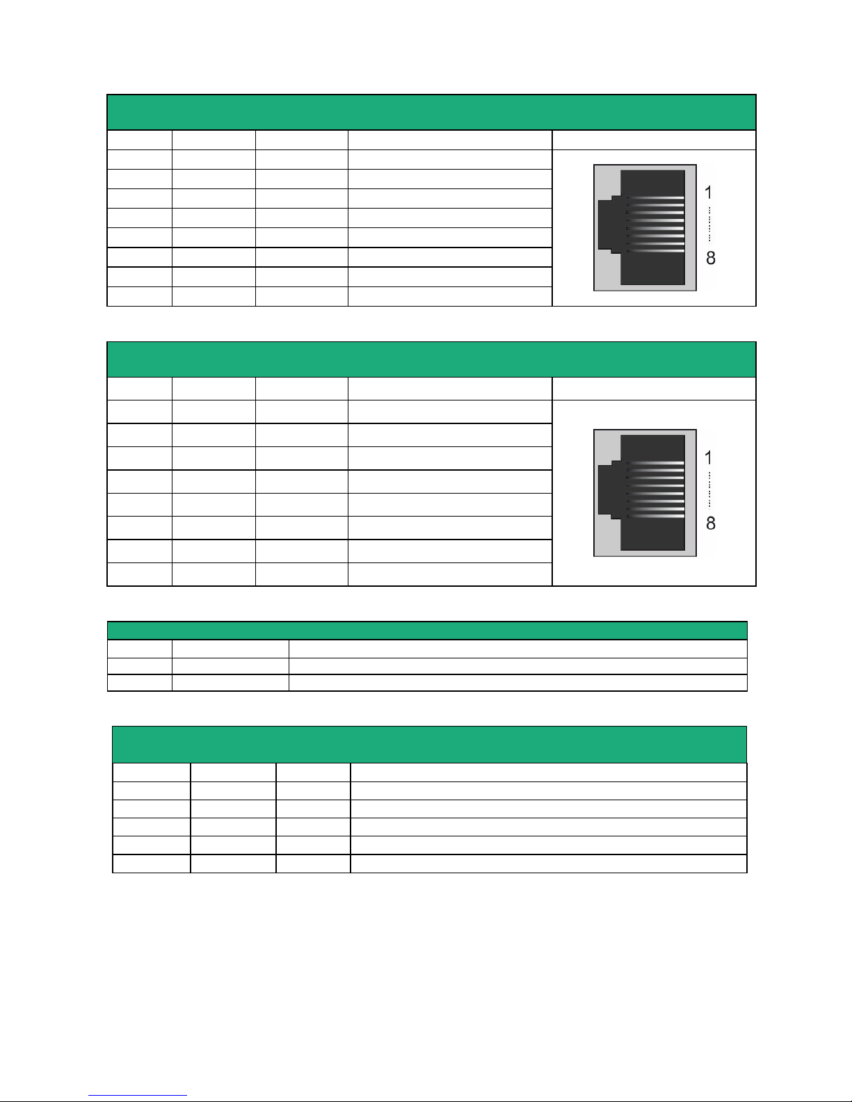
J45 RS232
DCE interface
Position
Signal Description RJ45
1 DTR - 108
OUT Data terminal ready
2 TD - 103
OUT Data Emission
3 RD - 104
IN Data Reception
4 DSR - 107
IN Data set ready
5 SG - 102
- Ground
6 Inutilisé
OUT -
7 CTS - 106
IN Clear to send
8 RTS - 105
OUT Request to send
Out = Signal provided by the router.
RJ45 RS232
DTE interface
Position
Signal Description RJ45
1 CD - 109
OUT
Carrier detect
2 RD - 104
OUT Data Reception
3 TD - 103
IN Data Emission
4 DTR - 108
IN Data terminal ready
5 SG - 102
-
Ground
6 DSR - 107
OUT Data set ready
7 RTS - 105
IN Request to send
8 CTS - 106
OUT Clear to send
Out = Signal provided by the router.
2 positions RS485 screw block
Position
Signal Fonction
1 A RS485 polarity A
2 B RS485 polarity B
5 positions RS422 screw block
IPL-A-260 IPL-AW-260
Position Signal Function
1 TX+ Sortie RS422 transmission polarity +
2 TX- Sortie RS422 transmission polarity 3 Com Common voltage
4 RX+ Entrée RS422 Reception polarity +
5 RX- RS422 Reception polarity -
Page 16
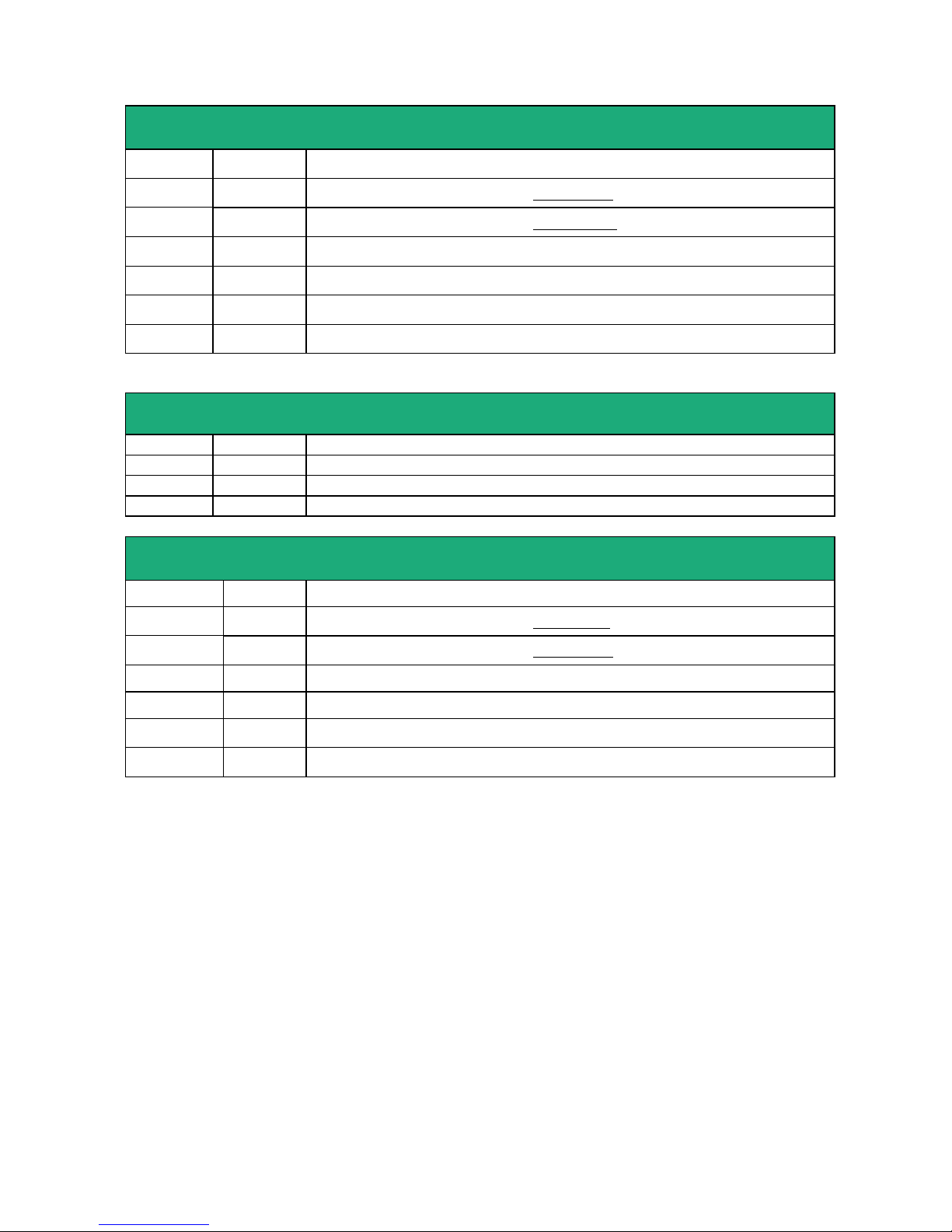
INSTALLATION
Page 16
User Guide 9021409-01 ADSL Router Firewall IPL-A
RS422
DIP switches
IPL-A-260 IPL-AW-260
SW 1 SW 2
ON ON The two 470 Ohm polarisation R. are enabled on the reception RS422 signal
OFF OFF The two 470 Ohm polarisation R. are disabled on the reception RS422 signal
SW3 SW4
ON ON The 120 Ohm termination R. is enabled on the reception RS422 signal
OFF OFF The 120 Ohm termination R. is disabled on the reception RS422 signal
2 positions RS485 screw block
IPL-A-261 IPL-AW-261
Position Signal Signal
1 Com Common
2 B (+) RS485 polarity B
3 A (-) RS485 polarity A
Micro
-
switches RS485
IPL-A-261 IPL-AW-261
SW 1 SW 2
ON ON
The two 470 Ohm polarisation R. are enabled
OFF OFF
The two 470 Ohm polarisation R. are disabled
SW3 SW4
ON ON
The 120 Ohm termination R. is enabled
OFF OFF
The 120 Ohm termination R. is enabled
Page 17
INSTALLATION
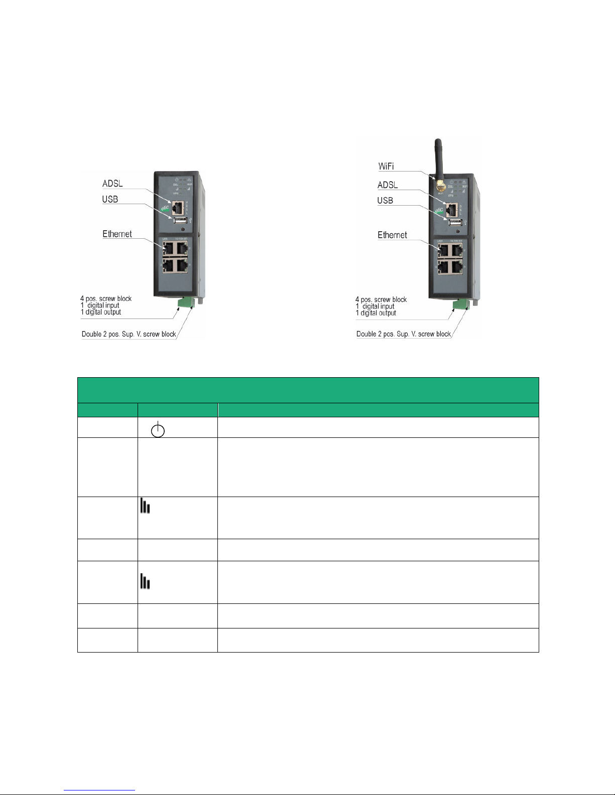
1.4 IPL-A-400 or IPL-AW-400 (WiFi option)
IPL-A-400 IPL-AW-400
LED INDICATORS
IPL-A-400 or IPL-AW-400
Designation
Function
Operation
Green The unit is ready
Flashing red Hardware default or unit start step
Ethernet
WAN
ADSL
Off ADSL interface disabled
Flashing T=4 s ADSL signal not still detected
Flasning T= 2 s ADSL connection on process
Flasning T= 0.5 s IP connection on process
Green Connected
ADSL signal
quality
Off WiFi not enabled or enabled as an access point
1 flash Weak not sufficient signal
2 flashes Sufficient signal
3 flashes Strong signal
WiFi
connection
WiFi
Off WiFi Interface not enabled
Green WiFi Interface enabled
WiFi
Signal
quality
WiFi
Off WiFi not enabled or enabled as an access point
1 flash Weak not sufficient signal
2 flashes Sufficient signal
3 flashes Strong signal
Ethernet LAN
1 to 4
Off Ethernet interface not connected
Green Ethernet interface connected
Upper led Ethernet 1 Green The RJ45 has been setup as the WAN interface
Page 18
INSTALLATION
Page 18
User Guide 9021409-01 ADSL Router Firewall IPL-A
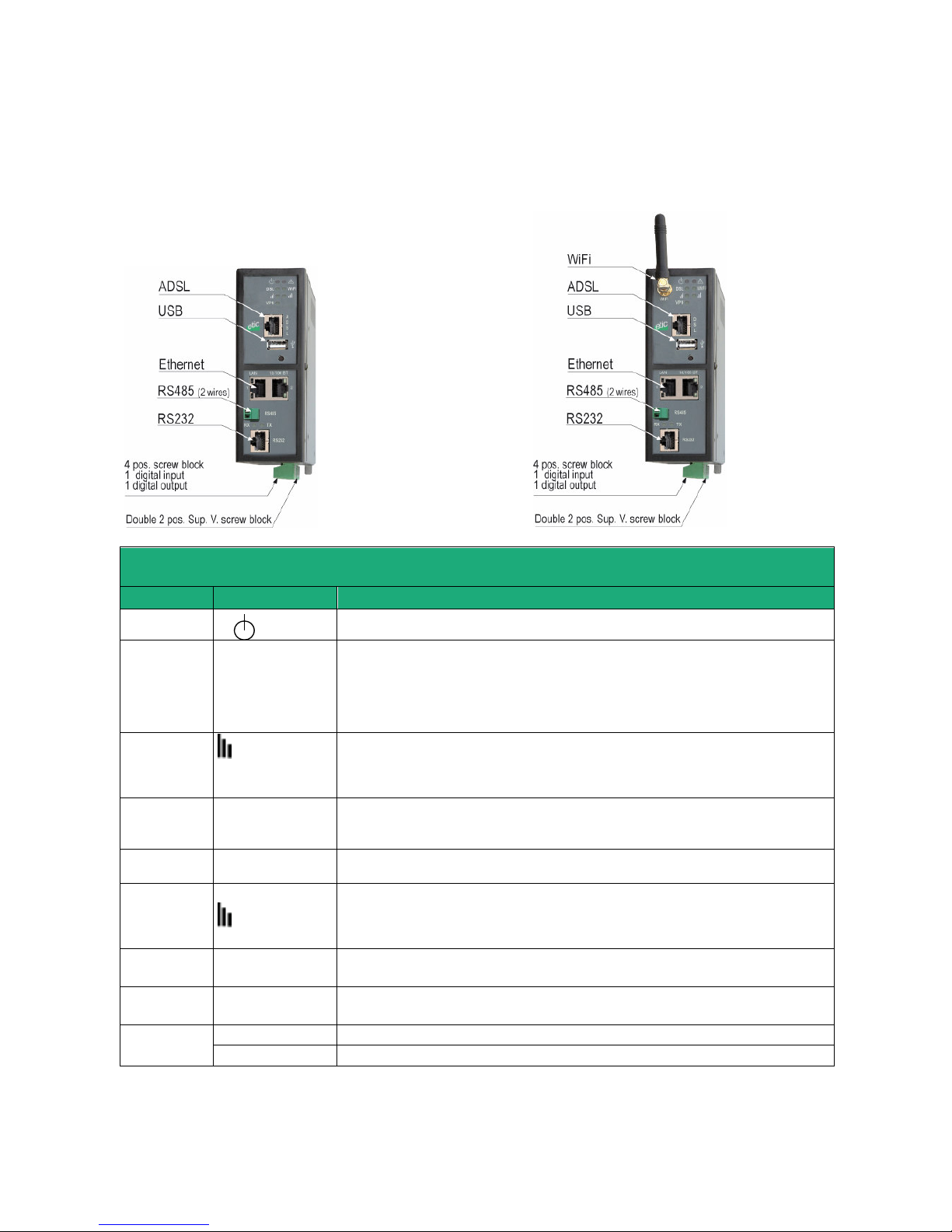
1.5 IPL-A-220 or IPL-AW-220 (WiFi option)
IPL-A-220 IPL-AW-220
LED INDICATORS
IPL-A-220 or IPL-AW-220
Designation
Function
Operation
Green The unit is ready
Flashing red Hardware default or unit start step
Ethernet
WAN
ADSL
Off ADSL interface disabled
Flashing T=4 s ADSL signal not still detected
Flasning T= 2 s ADSL connection on process
Flasning T= 0.5 s IP connection on process
Green Connected
ADSL signal
quality
Off WiFi not enabled or enabled as an access point
1 flash Weak not sufficient signal
2 flashes Sufficient signal
3 flashes Strong signal
VPN
Off No VPN has been enabled
Flashnig VPN processing
Green One VPN at least is established
WiFi
connection
WiFi
Off WiFi Interface not enabled
Green WiFi Interface enabled
WiFi
Signal
quality
WiFi
Off WiFi not enabled or enabled as an access point
1 flash Weak not sufficient signal
2 flashes Sufficient signal
3 flashes Strong signal
Ethernet LAN
1 to 2
Off Ethernet interface not connected
Green Ethernet interface connected
Upper led Ethernet 1 Green The RJ45 has been setup as the WAN interface
RS232
RS485
Rx
Characters received from the serial interface (to the IPL router)
Tx
Characters transmitted to the serial interface (from the IPL router)
Page 19
INSTALLATION
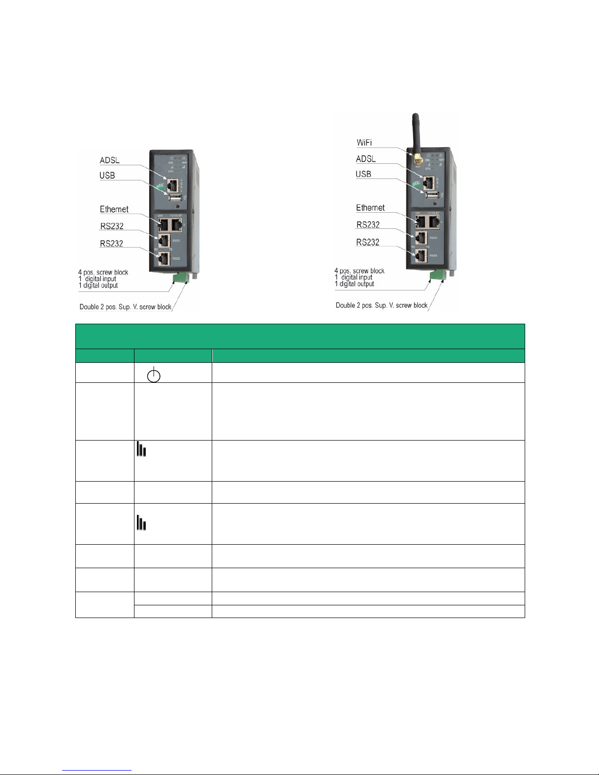
1.6 IPL-A-230 or IPL-AW-230 (WiFi option)
IPL-A-230 IPL-AW-230
LED INDICATORS
IPL-A-230 or IPL-AW-230
Designation
Function
Operation
Green The unit is ready
Flashing red Hardware default or unit start step
Ethernet
WAN
ADSL
Off ADSL interface disabled
Flashing T=4 s ADSL signal not still detected
Flasning T= 2 s ADSL connection on process
Flasning T= 0.5 s IP connection on process
Green Connected
ADSL signal
quality
Off WiFi not enabled or enabled as an access point
1 flash Weak not sufficient signal
2 flashes Sufficient signal
3 flashes Strong signal
WiFi
connection
WiFi
Off WiFi Interface not enabled
Green WiFi Interface enabled
WiFi
Signal
quality
WiFi
Off WiFi not enabled or enabled as an access point
1 flash Weak not sufficient signal
2 flashes Sufficient signal
3 flashes Strong signal
Ethernet LAN
1 to 2
Off Ethernet interface not connected
Green Ethernet interface connected
Upper led Ethernet 1 Green The RJ45 has been setup as the WAN interface
RS232
RS485
Rx
Characters received from the serial interface (to the IPL router)
Tx
Characters transmitted to the serial interface (from the IPL router)
Page 20
INSTALLATION
Page 20
User Guide 9021409-01 ADSL Router Firewall IPL-A
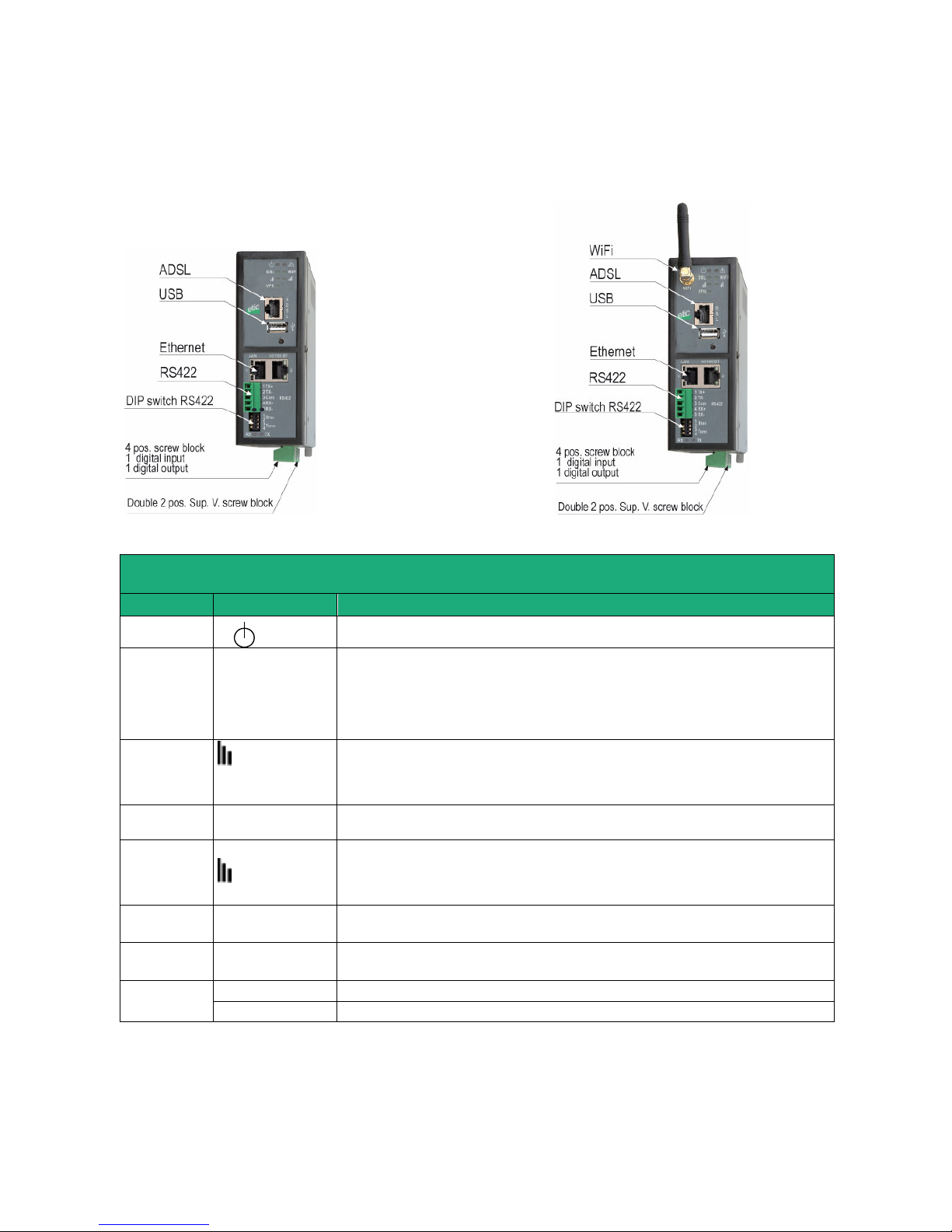
1.7 IPL-A-260 or IPL-AW-260 (WiFi option)
IPL-A-260 IPL-AW-260
LED INDICATORS
IPL-A-260 or IPL-AW-260
Designation
Function
Operation
Green The unit is ready
Flashing red Hardware default or unit start step
Ethernet
WAN
ADSL
Off ADSL interface disabled
Flashing T=4 s ADSL signal not still detected
Flasning T= 2 s ADSL connection on process
Flasning T= 0.5 s IP connection on process
Green Connected
ADSL signal
quality
Off WiFi not enabled or enabled as an access point
1 flash Weak not sufficient signal
2 flashes Sufficient signal
3 flashes Strong signal
WiFi
connection
WiFi
Off WiFi Interface not enabled
Green WiFi Interface enabled
WiFi
Signal
quality
WiFi
Off WiFi not enabled or enabled as an access point
1 flash Weak not sufficient signal
2 flashes Sufficient signal
3 flashes Strong signal
Ethernet LAN
1 to 2
Off Ethernet interface not connected
Green Ethernet interface connected
Upper led Ethernet 1 Green The RJ45 has been setup as the WAN interface
RS232
RS485
Rx
Characters received from the serial interface (to the IPL router)
Tx
Characters transmitted to the serial interface (from the IPL router)
Page 21
INSTALLATION
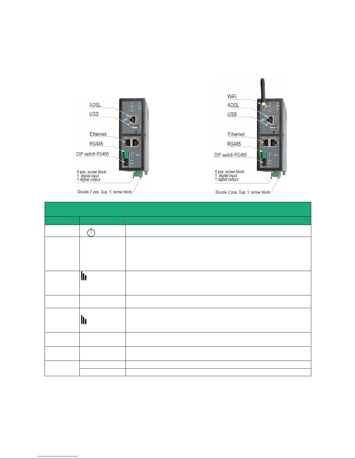
1.8 IPL-A-261 or IPL-AW-261 (WiFi option)
IPL-A-261 IPL-AW-261
LED INDICATORS
IPL-A-261 or IPL-AW-261
Designation
Function
Operation
Green The unit is ready
Flashing red Hardware default or unit start step
Ethernet
WAN
ADSL
Off ADSL interface disabled
Flashing T=4 s ADSL signal not still detected
Flasning T= 2 s ADSL connection on process
Flasning T= 0.5 s IP connection on process
Green Connected
ADSL signal
quality
Off WiFi not enabled or enabled as an access point
1 flash Weak not sufficient signal
2 flashes Sufficient signal
3 flashes Strong signal
WiFi
connection
WiFi
Off WiFi Interface not enabled
Green WiFi Interface enabled
WiFi
Signal
quality
WiFi
Off WiFi not enabled or enabled as an access point
1 flash Weak not sufficient signal
2 flashes Sufficient signal
3 flashes Strong signal
Ethernet LAN
1 to 2
Off Ethernet interface not connected
Green Ethernet interface connected
Upper led Ethernet 1 Green The RJ45 has been setup as the WAN interface
RS232
RS485
Rx
Characters received from the serial interface (to the IPL router)
Tx
Characters transmitted to the serial interface (from the IPL router)
Page 22
INSTALLATION
Page 22
User Guide 9021409-01 ADSL Router Firewall IPL-A
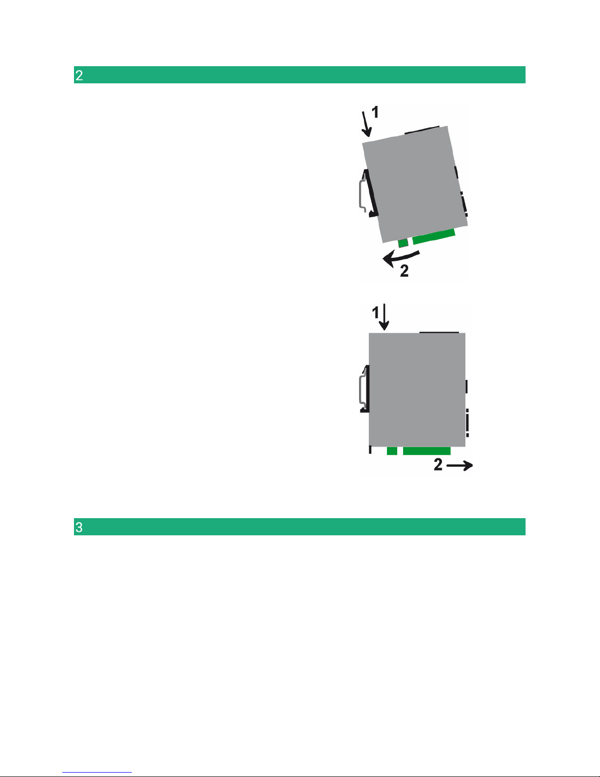
Mounting the product on a Din rail
Mounting the unit on the 35 mm horizontal DIN rail
Removing the unit from the DIN rail
Cooling
To avoid obstructing the airflow around the unit, the spacing must be at least 25 mm above and below, and
10 mm left and right.
Page 23
INSTALLATION
Supply voltage
IPL-A-400, IPL-AW-400
IPL-A-230, IPL-AW-230
IPL-A-260, IPL-AW-260
IPL-A-261, IPL-AW-261
Minimum input voltage : 10 V DC
Maximum input voltage : 60 VDC
IPL-A-220, IPL-AW-220 Minimum input voltage : 10 V DC
Maximum input voltage : 30 VDC
The consumption is lwer than 6 W.
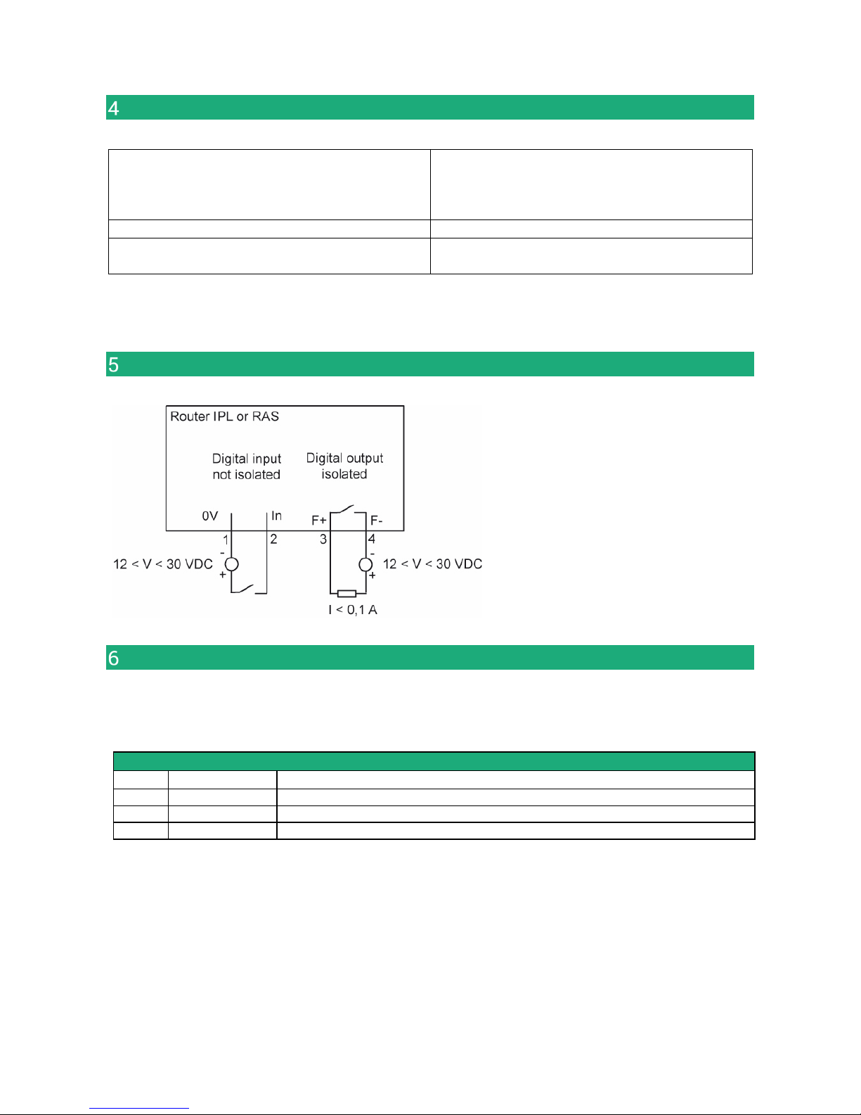
Digital input and output
To check that the input and the output are
correctly wired, select
Diagnostic > Hardware > Input / Output
The status of the input is displayed and
the output can be switched ON or OF.
RS232
The RS232 cable must be shorter than 10 meters.
Cables can be provided to connect the product to DTE and DCE as follows :
RS232 cables (L=1m)
Code User connector
Cable function
CAB592
SubD 9 male
To connect a DCE to the
router
CAB593
SubD 9 female
To connect a DTE to the
router
CAB609
Wires
To connect a device providing a specific connector
Page 24
INSTALLATION
Page 24
User Guide 9021409-01 ADSL Router Firewall IPL-A
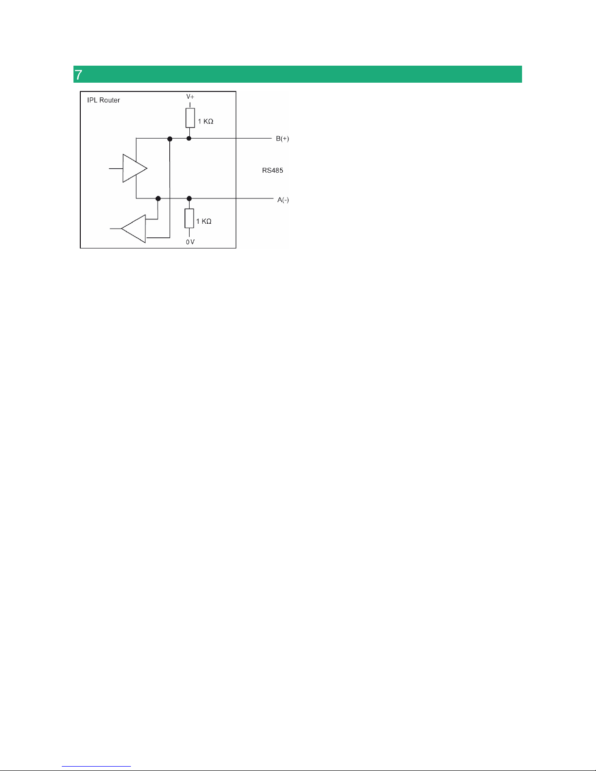
RS485 connection (IPL-A-220 or IPL-AW-220)
The RS485 serial interface is provided on the front
panel 2 positions screw-block.
It is not isolated.
Long RS485 line or high data rate
if the RS485 line is longer than10 meters or if the
data rate is greater than 19200 b/s, it is necessary
to connect one 120 Ohm matching resistor at each
end of the line and two 390 Ohm polarisation
resistors at one of the two extremities of the line.
Page 25
INSTALLATION
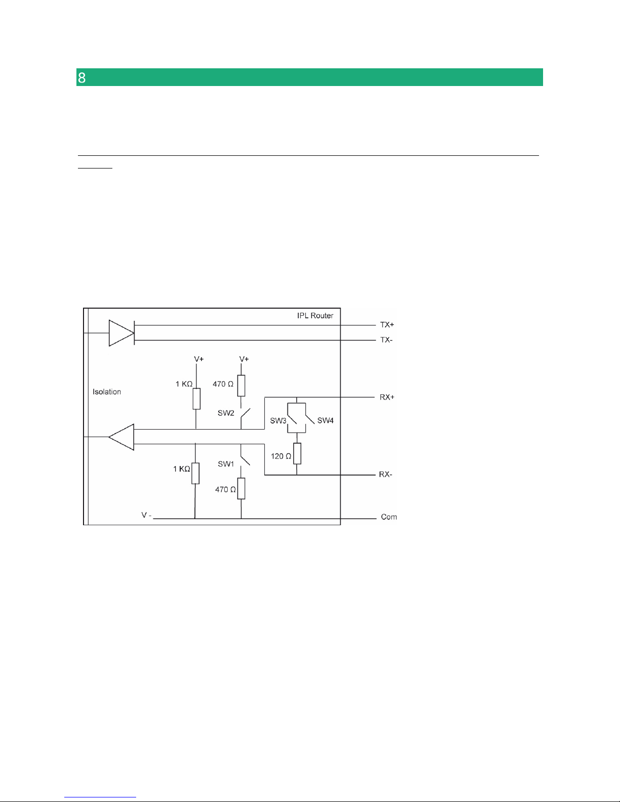
RS422 isolated interface (IPL-A-260 or IPL-AW-260)
The RS422 interface is isolated.
When two devices or more are connected to the RS422 interface of the IPL router, the IPL router must be
the only device to transmit data on the TX+/TX- line towards all the other devices.
It means that the TX+/TX- line of the IPL router must be connected to the RX+/RX- of all the other devices of
the bus.
The polarisation and termination resistors can be selected with DIP switches.
The polarisation résistors must be enabled by one device of the bus.
The termination resistor must be enabled with SW3 & SW4 when the router is located at the extremity of the
bus.
Up to 16 devices can be connected to the bus.
We recommend to use a shielded cable and twisted pairs.
If the line is exposed to lightning, we recommend to protect the router with a surge arrester.
Page 26
INSTALLATION
Page 26
User Guide 9021409-01 ADSL Router Firewall IPL-A
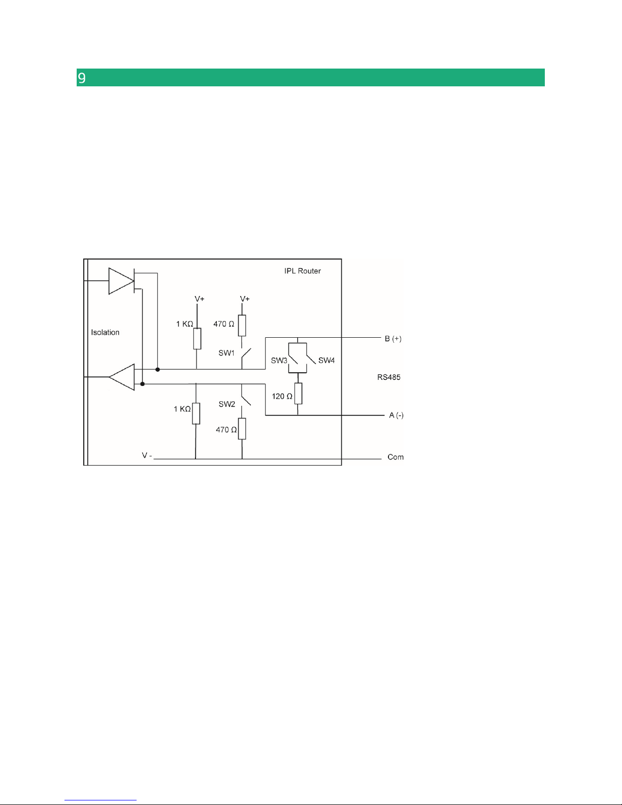
RS485 isolated interface (IPL-A-261 or IPL-AW-261)
The RS485 (3 wires : A- / B+ plus the common voltage wire) interface is isolated.
The polarisation and termination resistors can be selected with DIP switches.
The polarisation résistors must be enabled by one device of the bus.
The termination resistor must be enabled with SW3 & SW4 when the router is located at the extremity of the
bus.
Up to 16 devices can be connected to the bus.
We recommend to use a shielded cable and twisted pairs.
If the line is exposed to lightning, we recommend to protect the router with a surge arrester.
Page 27

INSTALLATION
Connecting the router to the ADSL line
The IPL-A router can be connected to an analogue line telephone line or an unbundled loop when the
attenuation of the reception signal is better than 63 dB
When the reception level is close to the limit, disconnections may occur.
In that situation, we recommend to ask to the ISP to setup the line with the RE-ADSL modulation which is
suited for long line and weak signal.
ADSL filter :
If the line must be used for analogue voice transmission simultaneously with ADSL transmission, it is
necessary to connect an ADSL filter.
Surge arrester :
The ADSL board of the IPL-A router is protected very carefully against over voltage coming from the line.
However, when the line is exposed to lightning, we recommend to connect a surge arrester between the line
and the IPL router.
Report to annex 1 for wiring.
Page 28

INSTALLATION
Page 28
User Guide 9021409-01 ADSL Router Firewall IPL-A
ADSL subscription
The IP address assigned by theISP to the ADSL interface of the router can be a fixed or a dynamic public IP
address.
If it is dynamic, it changes frequently; for instance at each ADSL connection.
It is why; the router which owns a dynamic IP address can only initiate the communication (initiate a VPN for
instance) towards a router owning a fixed IP address.
Reciprocally, a router owning a dynamic IP address cannot easily receive a connection except a DynDNS or
NoIP service is used.
The IP router is fully compatible with that services but we do not recommend to use that kind of service for a
critical industrial application.
Page 29
ADSL Router Firewall IPL-A User Guide 9021409-01
Page 29
PREPARING THE SETUP
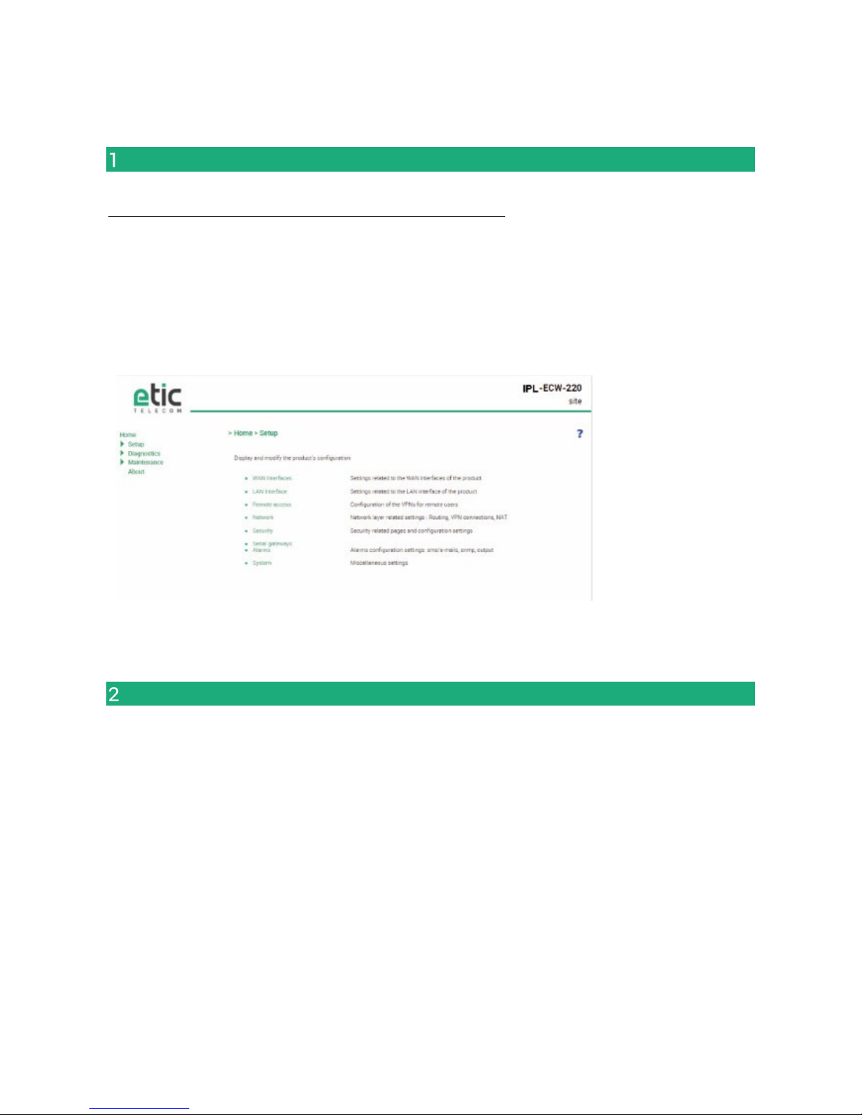
First setup
Coming from factory, the IP address of the router is 192.168.0.128.
Step 1 : Create or modify the PC IP connection.
Assign to the PC an IP @ in accordance with the IPL router IP address.
For the first configuration, assign for instance 192.168.0.127 to the PC.
Step 2 : Connect the PC directly to the LAN interface of the IPL router.
Step 3 : Launch the HTML browser : http://192.168.0.128
Protecting the access to the administration web server
• Select Set-up > Security > Administration rights.
• Enter an administration identifier and password.
Page 30

PREPARING THE SETUP
Page 30
User Guide 9021409-01 ADSL Router Firewall IPL-A
HTTPS set-up modifications through the WAN interface
The administration web server is located at the LAN IP address.
Coming from factory, access to the administration web server is not allowed through the WAN interface
To use HTTPS instead of HTTP to setup the product or to authorise access to the administration web server
through the WAN interface,
• Select Configuration > Security > Administration rights.
• Enter an administration identifier and password.
• Check the “HTTPS configuration” box.
• Check the “WAN access“ box if you wish to access to the administration web server through the WAN
interface.
Remark : the port Nr used to access to the administration web server with HTTPS is 4433.
Exemple : https://192.168.38.191:4433.
Recovering the factory LAN IP address
• Press the rear panel push-button ;
The OPERATION led indicator will flash.
The factory IP address 192.168.0.128 will be restored but the current configuration remains active.
Restoring the factory set-up
If firewall rules have been created finally preventing from reaching any IP address on the LAN interface
including the router itself, it may be necessary to restore the factory configuration of the router.
To restore the factory configuration,
•
Switch OFF the power supply of the IPL router.
•
Press the rear panel push button and, switch-on the power supply.
•
Keep the push button pressed until the operation led turns red.
Remark : The curent configuration is cleared and the factory IP address 192.168.0.128 is restored.
Page 31

PREPARING THE SETUP
Saving or restoring a set of parameters
Once a product has been set-up, the current set of parameters can be stored inside the router.
In a second step, any set stored inside the router and displayed with the Configurations table can be saved
as an editable file stored outside the ETIC router.
Inversely, a saved file can be loaded to the product Configurations table and then, if necessary, declared as
the active set of parameters.
• Select the Maintenance > configuration management menu
To store the current configuration set of parameters in the configurations table,
• Assign a name for the current set of parameters (“configuration name” field) and click the Save button.
The updated Configurations table is displayed with an additional line.
To save a stored set of parameters as an editable file
• Select the set of parameters name in the Configurations table,
• Click the Export to the PC button.
The set_of_parameters.txt file is created.
To import an editable **.txt file
• Click the Select a file button,
• Browse the PC and select the file,
• Click the Import from PC button.
The updated Configurations table is displayed with an additional line.
To select a configuration set of parameters in the Configuration table, as the current configuration
• Select the set of parameters name in the Configurations table,
• Click the Load button.
The selected set of parameters is now the current set of parameters.
Page 32

PREPARING THE SETUP
Page 32
User Guide 9021409-01 ADSL Router Firewall IPL-A
Configuration steps
To configure the router, we advise to proceed as follows :
•
ADSL interface setup
•
LAN interface setup
•
VPNs setup
•
Routing and IP address translation functions setup
•
Remote users connections, the user list and the access rights setup
•
Serial or USB gateway setup
•
Firewall setup
For detail about the configuration, refer to the IPL routers setup manual refernce 90 234 09.
Page 33

Page 34

ADSL Router Firewall IPL-A User Guide 9021409-01
Page 34
DIAGNOSTIC
Diagnostic
1.1 Logs
• Select the Diagnostic > Logs menu
Main logs
It registers
the ADSL connections & disconnections
the VPN connections & disconnections
theremote users connections & disconnections
The router starts
OpenVPN & IPSec Logs
These logs registers the detail of the VPN connections
Advanced logs
That logs registers details about the following events :
ADSL events
M2Me
RIP
DHCP
VRRP
Telnet gateway
Alarm emails
The filter checkbox allow to display particular classes of events.
Page 35

DIAGNOSTIC
1.2 Network status
To display the Interfaces status pages ,
• Select The Diagnostic > Network status>Interfaces menu.
The Interfaces page summarizes the current information of each interface of the router, like for instance :
LAN interface : MAC and IP address
Ethernet ports status
…
Ethernet WAN interface : MAC and IP address, default gateway address
Priority level
…
ADSL interface : Connection Status
IP address and remote IP address
Reception level
…
WiFi interface : Wifi mode (client or base station
Connection status
SSID
RF Frequency
…
To display the M2Me page,
• Select The Diagnostic > Network status> M2Me menu.
The M2Me page summarizes the current status of the M2Me connection and also displays the M2Me logs.
To display the remote users page,
• Select The Diagnostic > Network status> Remote users menu.
This page displays the table of the remote users currently connected.
To display the VPN connections page,
• Select The Diagnostic > Network status> VPN (IPSec or OpenVPN) menu.
This page displays the table of the Open VPN or IPSec VPNs currently connected.
Page 36

DIAGNOSTIC
Page 36
User Guide 9021409-01 ADSL Router Firewall IPL-A
To display the Routes page,
• Select The Diagnostic > Network status > Routes menu.
This page displays the table of the routes set-up by the router and the ARP table.
1.3 Serial gateways status
• Select the Diagnostic > Serial gateway menu
That page displays the current status of the serial gateways :
Type of the gateway (Modbus, RAW UDP or TCP, Telnet …),
serial port set-up (data rate etc…),
number of characters received or sent,
Number of TCP frames or UDP datagrams received or sent,
Number of TCP connections enabled.
The View link displays a window which shows the hexadecimal received and transmitted traffic over each
serial COM port.
It can be a great help for trouble shooting.
.
1.4 « Ping » tool
Select the Diagnostic > Tool > Ping menu.
Enter the PING destination IP address.
1.5 « WiFi » scanner tool
The Wifi scanner displays the main information about each WiFi network :
MAC address of the access point, SSID, reception level.
Remark : The WiFi interface of the ETIC router needs to be registered as a WiFi client interface.
Page 37

DIAGNOSTIC
Firmware update
The firmware update can be carried-out locally or remotely.
If the firmware update operation do not succeed, for instance if the connection fails, the ETIC router restarts
with the current firmware.
Once the firmware update has been carried-out, the ETIC router restores the previous current set of
parameters.
To update the firmware,
• Select Maintenance > Firmware update menu,
• Click the Select the firmware file button,
• Click Upgrade now.
When the firmware is updated, the product automatically reboots.
Page 38

Page 39
ADSL Router Firewall IPL-A User Guide 9021409-01
Page 39
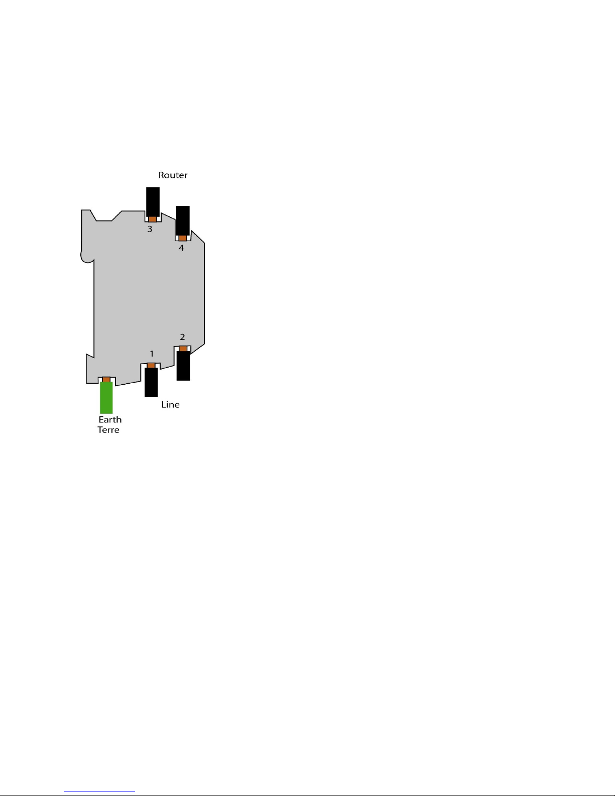
APPENDIX 1 : Wiring of the ADSL line surge arrester
Product reference : PS02-1
The wires 1 & 2 can be inverted.
The wires 3 & 4 can be inverted.
Page 40

ETIC TELECOM
13 chemin du vieux Chêne
38240 Meylan
France
[email protected]
 Loading...