

Page 1

IPL-3G
UMTS GPRS EDGE
IP Router - RAS - firewall
_________________
USER GUIDE
Document reference : 9019409-01
_________________
Page 2

Page 2 User guide ref 9019409-01 UMTS GPRS EDGE router ref. IPL-3G
The IPL-3G router is manufactured by
ETIC TELECOM
13 Chemin du vieux chêne
38240 MEYLAN
FRANCE
TEL : + 33 4-76-04-20-05
FAX : + 33 4-76-04-20-01
E-mail : [email protected]
web : www.etictelecom.com
Page 3

CONTENT
UMTS GPRS EDGE router ref. IPL-3G User guide ref. 9019409-01 Page 3
PRESENTATION
1 SECURITY RECOMMENDATIONS ............................................................................................................................7
2 CERTIFICATE OF CONFORMITY.............................................................................................................................9
3 PRODUCTS IDENTIFICATION ................................................................................................................................11
4 DATA-SHEET..........................................................................................................................................................13
5 PRODUCT OVERVIEW............................................................................................................................................15
5.1 Functions overview ..................................................................................................................................15
5.2 Main features.............................................................................................................................................17
INSTALLATION
1 DIMENSIONS ..........................................................................................................................................................19
2 CONNECTORS........................................................................................................................................................19
3 LED INDICATORS...................................................................................................................................................22
4 DIP SWITCHES .......................................................................................................................................................24
5 FACTORY DEFAULT PUSH-BUTTON.....................................................................................................................24
6 MOUNTING THE PRODUCT ON A DIN RAIL OR REMOVING IT.............................................................................24
7 COOLING................................................................................................................................................................26
8 RS232 INTERFACE.................................................................................................................................................26
9 RS485 INTERFACE.................................................................................................................................................27
10 DIGITAL INPUT AND OUTPUT ...............................................................................................................................27
11 CONNECTING THE ANTENNA................................................................................................................................27
12 INSTALLING THE SIM CARD .................................................................................................................................29
SET UP
1 SET UP STEPS .......................................................................................................................................................31
2 CONNECTING A PC TO THE ROUTER FOR CONFIGURATION .............................................................................32
2.1 Overview....................................................................................................................................................32
2.2 First configuration....................................................................................................................................32
2.3 Modifying the configuration from the LAN .............................................................................................33
2.4 Modifying the configuration from the WAN interface ............................................................................34
3 REBOOTING THE ROUTER AFTER PARAMETERS CHANGES..............................................................................34
4 RECOVERING THE FACTORY LAN IP ADDRESS...................................................................................................34
5 RECOVERING THE FACTORY CONFIGURATION .................................................................................................34
../..
Page 4

CONTENT
Page 4 User guide ref 9019409-01 UMTS GPRS EDGE router ref. IPL-3G
… SET UP
6 RESTRICTING ACCESS TO THE ADMINISTRATION SERVER...............................................................................35
7 RECOVERING A FREE ACCESS TO THE ADMINISTRATION SERVER..................................................................35
8 FACTORY CONFIGURATION..................................................................................................................................35
9 LAN INTERFACE SET UP......................................................................................................................................36
9.1 IP protocol .................................................................................................................................................37
9.2 DHCP server...............................................................................................................................................37
10 UMTS – GSM-GPRS-3GDGE INTERFACE SET UP.................................................................................................38
10.1 Modem menu.............................................................................................................................................38
10.2 Connection menu......................................................................................................................................38
10.3 “Control” menu .........................................................................................................................................40
11 SETTING A CONNECTION TOWARDS THE IPL-3G USING THE DYNDNS SERVICE .............................................41
12 CREATING VPN CONNECTIONS BETWEEN ROUTERS ........................................................................................42
12.1 Principles...................................................................................................................................................42
12.2 IPSec VPN connections ............................................................................................................................44
12.3 TLS VPN connections ...............................................................................................................................50
13 ROUTING FUNCTIONS ...........................................................................................................................................54
13.1 Basic routing function..............................................................................................................................54
13.2 Static routes ..............................................................................................................................................55
13.3 RIP protocol...............................................................................................................................................56
14 ADDRESS AND PORT TRANSLATION ...................................................................................................................57
14.1 Port forwarding .........................................................................................................................................57
14.2 Advanced network address and port translation...................................................................................58
15 VRRP REDUNDANCY..............................................................................................................................................62
15.1 Principle.....................................................................................................................................................62
15.2 Configuring VRRP on the LAN interface..................................................................................................62
15.3 Configuring VRRP on the WAN interface................................................................................................63
16 REMOTE USERS CONNECTIONS SERVICE ...........................................................................................................64
17 REMOTE USERS CONNECTIONS...........................................................................................................................65
17.1 Principles...................................................................................................................................................65
17.2 Configuring a TLS connection.................................................................................................................66
17.3 Configuring a PPTP connection...............................................................................................................68
../..
Page 5

CONTENT
UMTS GPRS EDGE router ref. IPL-3G User guide ref. 9019409-01 Page 5
… SET UP
18 M2ME_CONNECT SERVICE ...................................................................................................................................69
18.1 Overview....................................................................................................................................................69
18.2 Configuring a M2Me_Connect connection .............................................................................................70
19 USERS LIST............................................................................................................................................................71
20 FIREWALL..............................................................................................................................................................73
20.1 Overview....................................................................................................................................................73
20.2 Main filter...................................................................................................................................................74
20.3 Remote users filters..................................................................................................................................77
21 SERIAL TO IP GATEWAY.......................................................................................................................................81
21.1 Modbus menu............................................................................................................................................82
21.2 RAW TCP gateway.....................................................................................................................................84
21.3 RAW UDP gateway.....................................................................................................................................86
22 USB TO IP GATEWAY ............................................................................................................................................88
22.1 Principles...................................................................................................................................................88
22.2 Configuration ............................................................................................................................................88
23 ADVANCED FUNCTIONS........................................................................................................................................89
23.1 Adding a certificate...................................................................................................................................89
23.2 Alarms ........................................................................................................................................................89
23.3 Configuring the web portal ......................................................................................................................90
23.4 Configuring the DNS server .....................................................................................................................91
DIAGNOSTIC & MAINTENANCE
1 DIAGNOSTIC MENU ...............................................................................................................................................93
2 SAVING THE CONFIGURATION TO A FILE............................................................................................................95
3 UPDATING THE FIRMWARE ..................................................................................................................................96
Appendix 1 : Management web server description
Page 6

Page 7

SECURITY
UMTS GPRS EDGE router ref. IPL-3G User guide ref. 9019409-01 Page 7
1 Security recommendations
The IPL-3G is a low power radio transmission and reception device. It conforms to rules imposed to
UMTS or GSM-GPRS-EDGE terminals.
Check that using such a device is authorized at the location where you wish to install the router.
Do not use the IPL-3G router in locations with a potentially explosive atmosphere like, for instance,
petrol stations or areas where the atmosphere contains chemicals or particles.
The IPL-3G uses the UMTS radio network and wireless waves. It is why, it is not possible to
guarantee it will connect without interruption.
It is not possible to rely only the IPL-3G and the UMTS network to guarantee the security of an
automated system.
Page 8

Page 9

CONFORMITY
UMTS GPRS EDGE router ref. IPL-3G User guide ref. 9019409-01 Page 9
2 CERTIFICATE OF CONFORMITY
The manufacturer, ETIC Telecom – 13 chemin du vieux chêne – 38240 Meylan – France, Hereby
declares that the listed products
Type of device : UMTS & GSM - GPRS – EDGE router
Models: IPL-3G router family
conforms to the Council Directive 1999/5/EC related to radio and telecommunication terminal
equipments.
The harmonized standards to which the equipment complies are :
Standard Title
EN301489-1 Electromagnetic compatibility and Radio spectrum Matters :
Part 1 : General requirements
EN301489-7
Electromagnetic compatibility and Radio spectrum Matters :
Part 7 : Specific conditions for mobile and portable radio and ancillary equipment
of digital cellular radio
EN61000-6-2
Ed. 2001
Immunity :
EN60100-4-2 Electrostatic Discharge
EN60100-4-3 Radiated Immunity
EN60100-4-4 EFT/Burst Immunity
EN60100-4-5 Surge Immunity
EN60100-4-6 Conducted Immunity
EN61000-6-4
Ed 2001
Emission :
EN55022 radiated and conducted emission
EN60950 Security
EN50385 Human exposure to radio frequency fields exposure
EN301511 Global System for mobile communication
Gilles Bénas
Quality manager
5th december 2011
Page 10

Page 11

PRODUCT OVERVIEW
UMTS GPRS EDGE router ref. IPL-3G User guide ref. 9019409-01 Page 11
3 Products identification
IPL-3G-G -1400 -1400-B -1201 -1201-B -1220 -1220-B 1230 1230-B
Frequency band UMTS 850 1900 / 2100 MHz
Frequency band GSM GPRS 850 / 900 / 1800 / 1900 MHz
IP router • • • • • • • •
Remote access server PPTP or TLS - 25 users • • • • • • • •
Firewall SPI • • • • • • • •
Serial gateway - - - • • - • •
USB gateway - - • • - - - 25 IPSEC or SSL client or server VPNs • • • • • • • •
RJ45 10/100 BT 4 4 2 2 2 2 2 2
RS232 - - - - 1 1 2 2
RS485 - - - - 1 1 - USB host - - 1 1 - - - Port forwarding • • • • • • • •
Source IP address translation (NAT) • • • • • • • •
SNMP • • • • • • • •
DHCP client or server over the LAN interface • • • • • • • •
DHCP client 3G interface • • • • • • • •
RIP LAN & WAN • • • • • • • •
Digital input for emails 1 1 1 1 1 1 1 1
Html Configuration • • • • • • • •
IO Viewer compatible • • • • • • • •
VRRP - • - • - • - •
Masquerading - • - • - • - •
M2Me_Connect - • - • - • - •
Page 12

PRODUCT OVERVIEW
Page 12 User guide ref 9019409-01 UMTS GPRS EDGE router ref. IPL-3G
IPL-3G-E -1400 -1400-B -1201 -1201-B -1220 -1220-B 1230 1230-B
Frequency band UMTS 900 / 2100 MHz
Frequency band GSM GPRS 900 / 2100 MHz
IP router • • • • • • • •
Remote access server PPTP or TLS - 25 users • • • • • • • •
Firewall SPI • • • • • • • •
Serial gateway - - - • • - • •
USB gateway - - • • - - - 25 IPSEC or SSL client or server VPNs • • • • • • • •
RJ45 10/100 BT 4 4 2 2 2 2 2 2
RS232 - - - - 1 1 2 2
RS485 - - - - 1 1 - USB host - - 1 1 - - - Port forwarding • • • • • • • •
Source IP address translation (NAT) • • • • • • • •
SNMP • • • • • • • •
DHCP client or server over the LAN interface • • • • • • • •
DHCP client 3G interface • • • • • • • •
RIP LAN & WAN • • • • • • • •
Digital input for emails 1 1 1 1 1 1 1 1
Html Configuration • • • • • • • •
IO Viewer compatible • • • • • • • •
VRRP - • - • - • - •
Masquerading - • - • - • - •
M2Me_Connect - • - • - • - •
Page 13

PRODUCT OVERVIEW
UMTS GPRS EDGE router ref. IPL-3G User guide ref. 9019409-01 Page 13
4 Data-sheet
General characteristics
Dimensions 137 x 48 x 116 mm (h, l, p)
Electrical safety EN 60950- UL 1950
EMC
ESD : EN61000-4-2 : Discharge 6 KV
RF field : EN61000-4-3 : 10V/m < 2 GHz
Fast transient : EN61000-4-4
Surge voltage : EN61000-4-5 : 4KV line / earth
RoHS 2002/95/CE (RoHS)
Supply voltage
IPL-3G-X-1220 & IPL-3G-X-1220-B : 10 to 30 VDC - 300 mA / 24 VDC
IPL-3G-X-1230 & IPL-3G-X-1230-B : 10 to 60 VDC - 300 mA / 24 VDC
IPL-3G-X-1400 & IPL-3G-X-1400-B : 10 to 60 VDC - 300mA / 24 VDC
Operating T° -20°C / + 60°C Humidity 5 – 95 %
Air Interface
IPL-3G-G IPL-3G-E
Frequency UMTS 850 / 1900 / 2100 MHz 900 / 2100 MHz
Frequency GSM 850/ 900 / 1800 / 1900 MHz 900 / 2100 MHz
RF power
EGSM850 EGSM900 : class 4 (2 W)
GSM1800 GSM1900 : class 1 ((1 W)
Antenna Connector SMA
UMTS HSDPA HSDPA 7,2 Mb/s downlink / 384 kbps uplink
EDGE-GPRS 236,8 Kb/s downlink & uplink
GPRS Multislot class 12
Ethernet / IP router
Ethernet 10/100 BT – 2 or 4 switched ports
IP router Remote connections - static routes – RIP V2
IP address
translation
Source IP @ translation (NAT)
Destination IP @ translation (DNAT)
Port translation (Port forwarding)
DNS Domain name
IP address
assignment
Fixed IP @ or DHCP client or DHCP server
Security
VPN
Client or server IPSEC or TLS/SSL
Encryption 3DES
Certificate X509 or preshared key
25 VPNs maximum of the same type (TLS or IPSec)
Firewall Stateful packet inspection (50 rules)
Logs Date and time stamped logs
Page 14

PRODUCT OVERVIEW
Page 14 User guide ref 9019409-01 UMTS GPRS EDGE router ref. IPL-3G
Remote access server (RAS)
User list 25 users
Connection
VPN PPTP / L2TP-IPSec / TLS Open VPN
Login & password
Certificate X509
M2Me (*)
VPN Compliant with the M2Me_Secure VPN client
Compliant with the M2Me_Connect mediation service
Alarms 3 inputs : emails
Serial interface (*)
RS232
1200 – 115200 kb/s parity N / E / O
RS232 or RS485 (2 wires)
USB USB host interface
Serial
asynchronous to IP
gateways
Modbus master and slave
Raw TCP client and server
Telnet
RAW UDP “multicast”
unitelway
*option
Page 15

PRODUCT OVERVIEW
UMTS GPRS EDGE router ref. IPL-3G User guide ref. 9019409-01 Page 15
5 Product overview
5.1 Functions overview
The IPL- 3G router is designed to
interconnect safely automated devices
over the UMTS 3G or the GPRS-EDGE
service
The connection can be set with devices
connected to the Internet or with devices
connected to a private IP network or
between IPL-3G routers.
VPN can be set between routers to
provide safe and full communication
between the devices connected to the
routers.
The product includes an up-to-date serial
to IP gateway, enabling to connect
devices directly to the 3G network and the
Internet.
The IPL-3G is at the same time an IP
router, a VPN client or a VPN server, a
remote access server (RAS) and a stateful
packet inspection firewall.
The IPL-3G is a member of the range
of industrial routers manufactured by
ETIC TELECOM ; that family includes :
• an ADSL router
• an Intranet router (Ethernet interfaces)
• an up to 256 VPNs server rack
• a PSTN router
• an ISDN router
• a PPP RS232 router for particular
uses.
That range makes possible to build state-
of-the-art remote control systems.
Page 16

PRODUCT OVERVIEW
Page 16 User guide ref 9019409-01 UMTS GPRS EDGE router ref. IPL-3G
Due to its functions and its worldwide
3G module, the IPL-3G provides to
authorized users a remote access to
remote industrial devices or industrial
networks around the world through the
3G or GSM-GPRS network.
If the IP address assigned to the IPL-3G
router by the wireless service provider is
not fixed, It is possible to use either the
DynDNS service, or the M2Me_Connect
service provided by ETIC TELECOM.
The M2Me_Connect service makes
possible to set a secure connection
between
• A remote maintenance PC on one
hand,
• and an Ethernet or a serial Machine
network on the other hand through the
Internet.
The M2Me_Connect service is
specially efficient for remote
maintenance of automated systems.
The M2Me_Connect service makes
that connection possible and easy
even if the IP addresses of the PC on
one hand and of the Machine network
on the other hand are private and or
dynamic.
Page 17

PRODUCT OVERVIEW
UMTS GPRS EDGE router ref. IPL-3G User guide ref. 9019409-01 Page 17
5.2 Main features
The IPL-3G router provides the functions hereafter.
Remark : Some features are provided only on particular models.
IP router
The IPL-3G firewall-router provides powerful, flexible and comprehensive solutions to route IP
packets between the LAN and the 3G interface.
VPNs client or server
The IPL-3G router is able to establish safe VPN tunnels.
Once a VPN is established between two IPL-3G routers , each IP device connected to the first IPL-
3G can exchange IP packets with any device connected to the other IPL-3G.
The VPN mechanism ensures at the same time end-points authentication, data integrity and
confidentiality.
The IPL-3G router is able to establish up to 25 IPSec or TLS – SSL VPNs.
Authentication can be carried-out with a pre-shared key or with a certificate.
SPI Firewall
The IPL-3G incorporates a stateful inspection firewall.
It is able to check source and destination IP addresses and port numbers for data coming the from
the WAN interface or from the LAN interface.
Remote access server
Remote users are authenticated, an IP address belonging to the LAN interface is automatically
assigned to their PC.
Moreover, The traffic coming from the PC of each remote user is filtered according to the remote user
identity.
M2Me_Connect service *
The IPL-3G is compliant with M2Me_Connect, the remote connection service provided by ETIC
TELECOM over the Internet.
Serial gateway *
The product includes an asynchronous (RS232-RS485) to IP gateway, enabling to connect
asynchronous or USB devices directly and safely to the Ethernet network.
DHCP client or server
DHCP is a standard Internet protocol that enables a DHCP server to
dynamically distribute IP addresses and configuration information to the DHCP clients.
The IPL-3G can be a DHCP client or server on its LAN interface or a DHCP client on its 3G (WAN)
interface.
Emails – sms
An email (or SMS) can be sent each time one on the two digital inputs is opened or closed.
SNMP
The IPL-3G router is an SNMP agent.
Page 18

PRODUCT OVERVIEW
Page 18 User guide ref 9019409-01 UMTS GPRS EDGE router ref. IPL-3G
Html and DIP switches configuration
The IPL-3G is configured with a web server .
Two DIP switches allow to assign an IP address to the IPL-3G over the LAN interface : DHCP client
or server, factory IP address or stored IP address.
EticFinder software
The ETICFinder software is delivered with the product.
It detects the ETIC products connected to an Ethernet interface and displays the MAC address and
the iP address of each product.
M2Me_Secure VPN client software
M2Me_Secure is a TLS client able to register up to 100 VPN connections the user can set on a click.
* That feature is provided only on particular models; see the Product Identification table above.
Page 19

INSTALLATION
UMTS GPRS EDGE router ref. IPL-3G User guide ref. 9019409-01 Page 19
1 Dimensions
Dimensions
2 Connectors
IPL-3G-X-1220 IPL-3G-X-1230
IPL-3G-X-1400
Page 20

INSTALLATION
Page 20 User guide ref 99019409-01 UMTS GPRS EDGE router ref. IPL-3G
8 positions screw terminal : Supply voltage and digital input / output
Position Name Description
1 Power 1
+
IPL-3G-X-1220 or IPL-3G-X-1220-B : 10 to 30 VDC
All other models : 10 to 60 VDC
2 Power 1 - GND
3 Power 2
+
IPL-3G-X-1220 or IPL-3G-X-1220-B : 10 to 30 VDC
All other models : 10 to 60 VDC
4 Power 2 - GND
5 3V3 3 V DC provided by the IPL router
6 In Digital input
7 F + Digital output + (max 50Vdc - 0,6A)
8 F - Digital output -
RJ45 connector : Ethernet
Position Name Description
1 Tx + Emission polarity +
2 Tx - Emission polarity 3 Rx + Reception polarity +
4 N.C 5 N.C 6 Rx - Reception polarity 7 N.C. 8 N.C. -
RS485 screw terminal
Position Name Description
1 A RS485 polarity A
2 B RS485 polarity B
RS232 RJ45 connector port 1
(To connect to a DCE to the RS232 port)
Position Circuit Function
1 DTR - 108 OUT Data terminal ready
2 TD - 103 OUT Data Emission
3 RD - 104 IN Data Reception
4 DSR -
107
IN Data set ready
5 SG - 102 - Ground
6 Not used OUT 7 CTS - 106
IN Clear to send
8 RTS - 105 OUT Request to send
Page 21

INSTALLATION
UMTS GPRS EDGE router ref. IPL-3G User guide ref. 9019409-01 Page 21
RS232 RJ45 connector port 2
(To connect to a DCE to the RS232 port)
Position Circuit Function
1 Not used
2 TD - 103 OUT Data Emission
3 RD - 104 IN Data Reception
4 Not used
5 SG - 102 - Ground
6 Not used
7 Not used
8 Not used
Page 22

INSTALLATION
Page 22 User guide ref 99019409-01 UMTS GPRS EDGE router ref. IPL-3G
3 Led indicators
Indicator Status Description
All models
Flashing green
until connection to
the 3G network
After power-on, and during 30 seconds, the reception signal
strength is indicated by the number of flashes.
See the table below.
Remark : The diagnostic menu reports the value (dBm) of the
reception signal.
Line /
Green
Then , when the router is connected to the 3G network, this led is
lit.
Green The supply voltage is present
Green The unit is ready
Red
The product is starting
The SIM card is not present
The hardware is in failure
IPL-3G-X-1220 & IPL-3G-X-1220-B (with 1 RS232 and 1 RS485 interface)
Rx Flashing green Bytes received from the RS232 or RS485 (to IPL)
Tx Flashing green Bytes transmitted to the RS22 or RS485 (from IPL)
IPL-3G-X-1230 & IPL-3G-X-1230-B (with 2 RS232 interfaces)
Rx Flashing green Bytes received from the RS232 –1 interface (to IPL)
Tx Flashing green Bytes transmitted to the RS22 –1 interface (from IPL)
Rx Flashing green Bytes received from the RS232 –2 interface (to IPL)
Tx Flashing green Bytes transmitted to the RS22 –2 interface (from IPL)
RF reception signal strength indicator
Description Status
RF Reception dBm
(Diagnostic menu)
3 flashes
Good reception
-50 to - 80
2 flashes Sufficient reception
The level of the reception signal is sufficient to set a connection.
However, some error may occur which might decrease the data
rate.
-81 to –90
1 flash Insufficient reception
The level of the reception signal is weak ; errors and
disconnection might occur.
The reception conditions must be improved to get a reliable
connection
-91 to -110
Always OFF No reception
Control or replace the antenna or the product itself.
Can a communication be set with a mobile phone ?
< -111
Always ON The router is now connected to the 3G-GSM network
Page 23

INSTALLATION
UMTS GPRS EDGE router ref. IPL-3G User guide ref. 9019409-01 Page 23
Page 24

INSTALLATION
Page 24 User guide ref 99019409-01 UMTS GPRS EDGE router ref. IPL-3G
4 DIP switches
DIP switches
SW 1 SW 2 Management
OFF OFF The current IP@ of the product is the stored IP @
ON OFF
The active IP@ of the product is the factory IP@ : 192.168.0.128
No login and password are required to access to the html server
OFF ON The active IP@ is provided by the BOOTP or DHCP server.
ON ON Reserved
SW 3, SW 4 Not used
5 Factory default push-button
A push-button is located under the lid at the top of the product.
It enables to restore the factory profile.
• To restore the factory profile, switch the power on while pressing the push-button until the RUN light
turns green.
Attention : Once the factory profile has been restored, the stored configuration is lost.
6 Mounting the product on a DIN rail or removing it
Mounting the unit on the DIN rail
This unit should be mounted on 35 mm DIN-rail,
horizontally mounted.
Removing the unit from the DIN rail
Page 25

INSTALLATION
UMTS GPRS EDGE router ref. IPL-3G User guide ref. 9019409-01 Page 25
Page 26

INSTALLATION
Page 26 User guide ref 99019409-01 UMTS GPRS EDGE router ref. IPL-3G
7 Cooling
To avoid obstructing the airflow around the unit, the spacing must be at least 25 mm above and
below, and 10 mm left and right.
8 RS232 interface
The RS232 data rate can be set from 1200 to 115200 b/s with parity (even / odd) or no parity.
The data terminal must be less than 10 meters far from the modem.
Cables can be provided to connect the product to DTE and DCE as follows :
RS232 cables (L=1m)
Code User
connector
Cable function
CAB592 SubD 9 male To connect a DCE to the IPL-3G
CAB59
3
SubD 9
female
To connect a DTE to the IPL-3G
CAB60
9
Wires To connect a device providing a specific connector
CAB593 cable - DB9 female RS232 connector
Position Circuit Name IPL - Terminal
1 CD 109 Carrier detect
⇒
2 RD 104 Data Reception
⇒
3 TD 103 Data Emission
⇐
4 DTR 108 Data terminal ready
⇐
5 GND 102 Ground
6 DSR 107 Data set ready
⇒
7 RTS 105 Request to send
⇐
8 CTS 106 Clear to send
⇒
9 RI 125 Ring indicator
⇒
CAB592 cable - DB9 male RS232 connector
Position Circuit Name IPL - Terminal
1 CD 109
⇐
2 RD 104 Data Reception
⇐
3 TD 103 Data Emission
⇒
4 DTR 108 Data terminal ready
⇒
5 GND 102 Ground
6 DSR 107 Data set ready
⇐
7 RTS 105 Request to send
⇒
8 CTS 106 Clear to send
⇐
9 RI 125 Ring indicator
⇐
Page 27

INSTALLATION
UMTS GPRS EDGE router ref. IPL-3G User guide ref. 9019409-01 Page 27
9 RS485 interface
The RS485 serial interface is provided on the front panel 2 pins
screw-block.
Polarisation resistors
1 Kohm bus polarisation resistors are included inside the product.
RS485 line adaptation
For a several meters long connection over the RS485 local interface, it is not necessary to adapt the RS485 line. For a longer
distance, connect a 120 Ohm resistor at each end of the line.
10 Digital input and output
Digital output :
Max. voltage : 48 VDC
Max. current : 500 mA
Digital input :
Maximum voltage : 20 VDC
11 Connecting the antenna
If the cabinet in which the router has to be installed is made of metal, the antenna has to be installed outside the cabinet; for
instance on its top.
The antenna must be ordered separately; the models below are available :
• 90 ° antenna (ANT210 ).
• Magnet mount antenna (ANT211)
• Roof antenna (ANT212)
-
1K 1K
+
SW1
B(+) A(-)RS485
F+ F-
7
8
Digital output
+
V < 48 VDC
I < 0,5 A
3V3 In
5
6
Digital input
I max = 0,5 A
V
IPL router
Page 28

INSTALLATION
Page 28 User guide ref 99019409-01 UMTS GPRS EDGE router ref. IPL-3G
ANT211 ANT212 (1,50 m)
Page 29

INSTALLATION
UMTS GPRS EDGE router ref. IPL-3G User guide ref. 9019409-01 Page 29
12 Installing the SIM card
Before installing the SIM card into the router, its PIN code must have been cleared.
The PIN code can be cleared using a usual telephone or a smart phone.
Step 1 : Install the SIM card
• Power off the router.
• Remove the anti-steal lid at the top of the product
• Press the SIM card eject button and remove the SIM card drawer.
• Insert the SIM card SIM card drawer.
• Slid the drawer back into the unit and make sure it locks into place.
Step 2 : Check the reception signal strength
• Switch-on the router
• The led first lights red and then green.
• The power indicator lights green.
• The reception led flashes to indicate cyclically the reception signal strength.
The reception led must flash at least 2 times to ensure a reliable connection.
If the reception led flashes only one time, the reception is poor ; it must be improved otherwise the
connection will be probably not reliable.
If the reception led remains OFF, it means that the 3G service cannot be received at that location or
that the antenna is not correctly connected or is damaged.
• If the led lights red, it signifies that the PIN code of the SIM card has not been cleared.
Page 30

Page 31

SET UP
UMTS GPRS EDGE router ref. IPL-3G User guide ref. 9019409-01 Page 31
1 Set up steps
To configure the router, we advise to proceed as follows :
• Connecting a PC to the router
• Setting up the LAN interface
• Setting up the WAN interface
• Setting up VPNs
• Setting up routing and IP address translation functions
• Setting the 3G backup function (IPL-3G-1201B)
• Setting up remote users connections and the M2Me_Connect service
• Setting up the remote users list
• Setting up the serial gateway or the USB gateway
• Setting up the firewall
The IPL-3G router is configured with a PC and an HTML browser.
2 DIP switches enable you to set the IP address : Factory address, stored address, BootP or DHCP
client or server.
For the first configuration, we advise to connect the PC directly to the router Ethernet interface.
Modifications can be carried out through the LAN or remotely.
Page 32

SET UP
Page 32 User guide ref 9019409-01 UMTS GPRS EDGE router ref. IPL-3G
2 Connecting a PC to the router for configuration
2.1 Overview
Administration server address :
The administration html server is located at the LAN IP address of the router. The default factory address
is192.168.0.128.
First setup :
For the first configuration, we advise to connect the PC directly to the LAN interface of the IPL-3G router.
Setup modifications from the LAN or remotely :
Modifications can be carried out
from the LAN interface,
or from the Internet using a port forwarding rule (not advised for security reasons),
or using a remote user connection PPTP, TLS, L2TP/IPSec,
or through a VPN.
Restoring the factory IP address :
The factory IP address of the router on the LAN interface can be restored by setting the DIP switches SW01 ON and
SW02 OFF.
In that position of the DIP switches, the stored configuration is not deleted.
Setting the DIP switches in that position gives also a free access to the administration server from the LAN interface.
During operations, the DIP switches must not be left in that position.
Network IP address :
Later in the text, we often speak of “network address”.
We mean the lowest value of the addresses of the network.
For instance, if the netmask of a network is 255.255.255.0, the network address of that network is X.Y.Z.0.
Copy and paste :
Parameters must be entered with the keyboard; they cannot be pasted.
However, it can be useful to paste a string when it is long to avoid errors.
In that case, paste the string, delete the last character of the pasted string, and enter it again with the keyboard.
Saving and restoring the parameters file (see the maintenance chapter)
A parameters file can only be downloaded to a product having the same firmware version. It is why, we advise to
assign a name to a parameter file including the product name and the software version like for instance
“myrouterfile_iplE1220_V241.bin”.
2.2 First configuration
Step 1 : Check the DIP switches
Coming from factory, the DIP switches SW1 and SW2 are set OFF to select the stored IP address.
Coming from factory, the stored IP address is the factory IP address 192.168.0.128.
Step 2 : Create or modify the PC IP connection.
Assign to the PC an IP @ in accordance with the IPL-3G IP address.
For the first configuration, assign or instance 192.168.0.127 to the PC.
Step 3 : Connect the PC directly to the LAN interface of the IPL-3G router using any Ethernet
cable (straight or cross wired).
Step 4 : Launch the navigator
Enter the LAN IP @ of the router 192.168.0.128.
Page 33

SET UP
UMTS GPRS EDGE router ref. IPL-3G User guide ref. 9019409-01 Page 33
The Home page of the administration server is displayed
2.3 Modifying the configuration from the LAN
• If the IP @ of the IPL-3G on the LAN interface is fixed
Step 1 : Ensure the DIP switch SW1 and SW2 are OFF to select the stored IP @.
Step 2 : Launch the html browser and enter the IP address assigned to the router.
Or, launch the ETICFINDER utility to detect the IPL-3G address.
Remark :
If the home page cannot be displayed, refer below.
• If the IP @ of the IPL-3G on the LAN interface is assigned by a DHCP server
Step 1 : Ensure the DIP switch SW1 is OFF and SW2 ON to select DHCP client operation.
Step 2 : Launch ETIC FINDER to detect the IPL-3G address over the LAN interface.
Click the product once detected.
The Home page of the administration server is displayed.
Remark :
If the home page cannot be displayed, refer below.
Page 34

SET UP
Page 34 User guide ref 9019409-01 UMTS GPRS EDGE router ref. IPL-3G
2.4 Modifying the configuration from the WAN interface
Coming from the factory, the firewall rejects all the packets coming from the WAN to the LAN.
To modify remotely the configuration, one can use one of the methods described hereafter :
Set a remote user PPTP, TLS, L2TP/IPSec connection towards the antenna iP address of the IPL-3G router.
Connect a PC to the IPL-3G through a VPN set between the IPL-3G t and another router.
Set up a port forwarding rule to authorise IP frames transmitted to the antenna IP address to be
forwarded to the LAN IP address of the IPL-3G router.
3 Rebooting the router after parameters changes
• After the parameters of any page have been completed, click the « Save » button at the bottom
of the page.
• After some parameters changes, the IPL-3G must restart.
When the configuration has been completely carried out, click the « Reboot » red button in the green
bar, when displayed.
• Once the product has restarted, check the « Reboot » button has disappeared from the green
bar.
To save the configuration file to a hard disk :
• Select the “maintenance” menu and then the “Save / restore” menu.
• Click the “Save current configuration to disk” button.
4 Recovering the factory LAN IP address
When launching the html browser, the homepage of the html server may not be displayed; the cause
may be the IP address you entered was wrong.
if the IP address you enter is wrong, you can recover the factory IP address by setting SW01 ON
and SW2 OFF but the configuration of the router is not lost.
The factory IP address 192.168.0.128 will be restored as long as the SW01 and SW02 micro switch
will be left in that position.
Remark :
The SW01 and SW02 must not be left in that position during operations.
5 Recovering the factory configuration
If firewall rules have been created finally preventing from reaching any IP address on the LAN
interface including the router itself, it may be necessary to restore the factory configuration of the
router.
To restore the IPL-3G factory configuration,
• Switch OFF the power supply of IPL-3G router.
• Press the push button located on the top part of the IPL-3G router under the lid and, switch-on the
power supply.
Page 35

SET UP
UMTS GPRS EDGE router ref. IPL-3G User guide ref. 9019409-01 Page 35
• Keep the push button pressed until the operation led turns red.
Remark : The stored configuration will be lost; the factory IP address 192.168.0.128 will be restored.
6 Restricting access to the administration server
When the IPL-3G comes from factory, the html server is not protected by a password.
It is advised to protect the access to the administration server with a login and a password.
To protect access to the administration server,
• Select the “Setup” menu, the “Security” menu and then the “Administration menu”.
Remark : For more simplicity, we advise to chose the login and the password of one of the remote
users stored in the user list.
7 Recovering a free access to the administration server
If the Login & or password entered to reach the administration server have been rejected, it is
possible to recover a free access to the administration server from the LAN only, by setting SW01
ON and SW2 OFF.
Remark :
The factory IP address 192.168.0.128 will also automatically be restored as long as SW01 will
remain ON and SW2 OFF.
During normal operations SW01 and SW02 must not be left in that position.
8 Factory configuration
Coming from factory, the router configuration is as follows :
LAN IP @ 192.168.0.128
WAN IP @ None
Default user : Login = admin ; Password = admin
Admin. Web server restriction : None
Firewall :
Remote user filters Authorises any remote users belonging to the user list to reach a LAN IP address using
a PPTP or TLS connection
Main filter IP frames coming from the WAN interface to the LAN are dropped
IP frames transported inside a VPN are forwarded
Page 36
SET UP
Page 36 User guide ref 9019409-01 UMTS GPRS EDGE router ref. IPL-3G
9 LAN interface set up
The LAN interface is made of 4 Ethernet switched ports or of 2 Ethernet switched ports and 2 serial
ports or 2 serial port and 1 USB port.
On that interface, the following IP addresses must be entered :
The router IP address on the LAN interface *.
The IP address pool assigned to the remote users when they connect.
* The administration server is located at that address.
On the LAN interface, the IPL-3G can behave like a DHCP server.
Remark about IP addresses assignment rules :
The IPL-3G router will be able to route frames between the LAN and the WAN interface only if the IP
address assigned to the network connected to the LAN interface is different from the one assigned to
the WAN interface.
Moreover , through a VPN, the LAN IP address must be different from the remote LAN IP address
Page 37

SET UP
UMTS GPRS EDGE router ref. IPL-3G User guide ref. 9019409-01 Page 37
9.1 IP protocol
• Click the « Configuration» menu and then « LAN interface» and then “IP protocol”.
“IP address” parameter :
Enter the IP address assigned to the router over the LAN interface.
That IP address will have to be entered to display the administration server of the router.
”Netmask” parameter :
Enter the IP netmask assigned to the LAN
“Start of users IP address pool” & “end of users IP addresses pool” parameters :
That parameters define the pool of addresses which will be assigned automatically to remote user’s PC when
they will connect to the router.
Enter the start address and the end address.
Remark :
After the LAN IP address of the router has been modified, it is necessary to reboot the unit.
If VPNs have been created, they must be launched again after the LAN IP address has been modified.
To launch the VPNs again after the LAN IP address has been modified,
• Select the « network» menu and then the « VPN » menu,
• Click the « Properties » button in front of the « type of VPN » field, and then on the “OK” button
of the window entitled« VPN properties».
• Click the « Modify » button in front of the « VPN connection » field, and then on the “OK” button.
If the DHCP server is used, it must be launched again after the LAN IP address has been modified.
To launch again the DHCP server after the LAN IP address has been modified,
• Select the « LAN interface» menu and the «DHCP server» menu,
• Unselect the « Enable the DHCP server» checkbox, and then select it again.
9.2 DHCP server
Over the LAN interface, the IPL-3G router can behave like a DHCP server.
• To configure the DHCP server function, select the « Setup» menu and then « LAN interface»
and then « DHCP server ».
“Activate DHCP server” checkbox :
Select that checkbox to enable the DHCP server.
“IP address pool start” & “IP addresses pool end” parameters :
That parameters define the range of IP addresses which can be assigned by the IPL-3G to the DHCP client
devices.
“Netmask” & “default gateway” parameters :
Enter the netmask of the network connected to the LAN interface and the default gateway address.
« Primary DNS IP address” & “secondary DNS IP address” parameters :
Enter the IP addresses of the domain name servers.; the DHCP server will communicate that
information to the DHCP client devices.
“Client MAC address” “Client IP address” table :
Page 38

SET UP
Page 38 User guide ref 9019409-01 UMTS GPRS EDGE router ref. IPL-3G
If a fixed IP address must be assigned to the devices connected to the LAN interface, enter the MAC
address and the fixed Ip address of each of these devices.
10 UMTS – GSM-GPRS-3GDGE interface set up
The IPL-3G router’s UMTS – GSM-GPRS-EDGE interface is configured through the WAN interface
menu :
The 3G modem interface is configured through the « Modem » page.
The PPP interface to the provider is configured through the « Connection » page.
The conditions at which the 3G connection can be reset is configured through the « Control » page.
Remark : Once that operations will have been carried out, check the Reception indicator is
permanently ON. It signifies the IPL-3G is now connected to the UMTS network.
10.1 Modem menu
• Select the « Configuration» menu and then « WAN interface» and then “Connection”.
“APN” parameter :
Enter the APN code assigned by the GSM operator.
”User name” & “password” parameters :
Enter the user name and password assigned by the GSM operator.
Remark : If no user name or password have been assigned by the GSM operator, enter at least an
alphabetic character in each field.
10.2 Connection menu
• Select the « Configuration» menu and then « WAN interface» and then “Connection”.
“Obtain an IP address automatically” checkbox :
Set that option if the provider assigns automatically an IP address to the router through the air
interface each time it connects to the 3G or GSM network.
Remark : In most cases, and in particular when the Ipl-3G is connected to the Internet, that checkbox must be selected.
“IP address” & “netmask” parameter :
Enter the fixed IP address and netmask assigned to the router if it not assigned through the air
interface.
“Obtain DNS IP addresses automatically” checkbox : Select that checkbox if the Domain name
servers IP addresses are provided automatically through the air interface.
Remark : In most cases, and in particular when the IPL-3G is connected to the Internet, that checkbox must be
selected.
“Primary DNS IP address” & “secondary DNS IP address” parameters :
Enter the IP addresses of the domain name servers if they are not assigned through the air interface.
“Activate network address translation” checkbox :
If that option is selected, the source IP address of any frame coming from a device connected to the LAN interface and
routed to the WAN interface , is replaced by the router WAN IP address.
Remark : In most cases, and in particular when the Ipl-3G is connected to the Internet, that checkbox must be selected.
”SMTP server” parameter :
Enter the address of the SMTP server for outgoing mails (ex : smtp.nerim.net)
Page 39

SET UP
UMTS GPRS EDGE router ref. IPL-3G User guide ref. 9019409-01 Page 39
“Source account e-mail address” parameter :
Enter the email address attached to the account.
Page 40

SET UP
Page 40 User guide ref 9019409-01 UMTS GPRS EDGE router ref. IPL-3G
10.3 “Control” menu
The IPL-3G router may not detect that the 3G connection has been cleared ; it is why, the router can
send a periodical PING to a particular address.
If one that PING does not receive an answer, and after several retries, the 3G connection is reset by
the IPL-3G router.
• To set-up that function, select the « Configuration» menu and then « WAN interface» and then
“Control”.
“Enable the ping control” checkbox :
select that checkbox.
“IP address to ping” parameter :
Enter the IP address of the server to which the IPL-3G will transmit periodically a PING to control the
connection works correctly.
“Ping period” parameter :
Enter the value of the period of the PINGS.
“Ping retries” parameter :
If a PING does not receive an answer, the router will repeat PINGS at a high frequency. If that high
frequency PINGS do not receive an answer after a certain number of retries, the connection is reset.
Enter the number of times the router has to repeat the PING request at a high frequency before
declaring the connection in failure.
Page 41

SET UP
UMTS GPRS EDGE router ref. IPL-3G User guide ref. 9019409-01 Page 41
11 Setting a connection towards the IPL-3G using the DynDNS service
Remark :
The DynDNS service is free; but the dyndns domain name can be cancelled if it is not periodically
used.
The DynDNS service cannot be used to reach the antenna of the IPL-3G router if the IP address
assigned to the Ipl-3G router is not a public IP address.
If the IP address assigned to the antenna of the router on the 3G network is public but not
fixed, it is possible to use the DynDNS service to set a connection from a device connected to the
internet toward a device connected to the IPL-3G router.
To enable the DynDNS service proceed as follows :
• Reserve a dynDNS domain name on the dyndns.org web site.
For instance mymachine.dyndns.org.
• Select the« Set up » menu, and then WAN interface, and then “dynamic.IP address” .
« Enable» checkbox :
Select that checkbox.
« DNS account login” parameter :
Enter the login assigned by dyndns.
« DNS account password” parameter :
Enter the password assigned by dyndns.
« Hostname» parameter :
Enter the DynDNS domain name (for instance mymachine.dyndns.org).
• When you wish to set a connection toward the IPL-3G (PPTP, TLS, VPN …), enter the DynDNS
host name instead of the antenna IP address of the IPL-3G router.
Page 42

SET UP
Page 42 User guide ref 9019409-01 UMTS GPRS EDGE router ref. IPL-3G
12 Creating VPN connections between routers
12.1 Principles
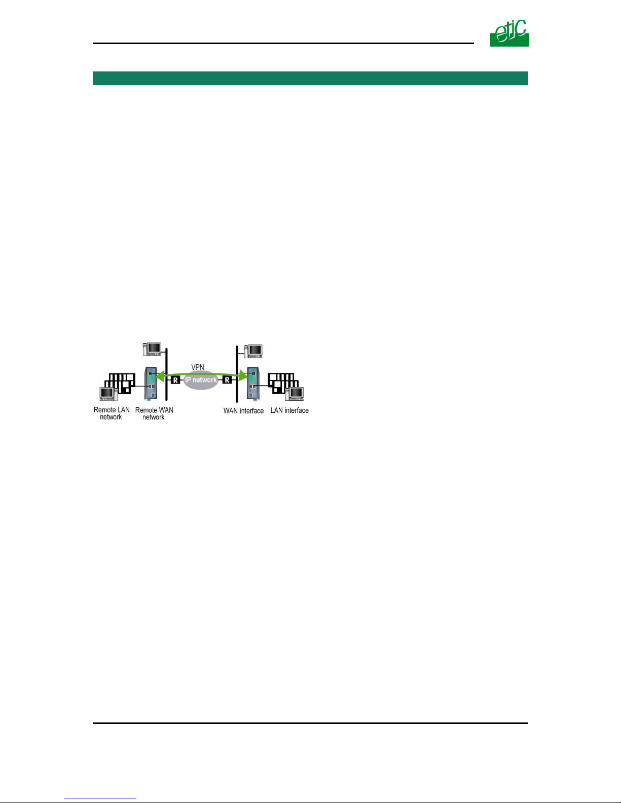
A VPN tunnel is a safe link set between two end-points routers over an IP network : Both routers
authenticate, data are encrypted and each device of a LAN can exchange data with each device f the
other one.
To get more explanations about how VPNs work, refer to appendix 1.
25 VPNs can be set on the WAN interface of the IPL-3G router.
Two types of VPN can be set : TLS VPN and IPSec VPN.
IPSec has the advantage to be a standard solution.
TLS is easier to employ because the transport layer is TCP or UDP; it is why, it can be easily used
when the VPN must pass through several or even numerous company routers.
Once a type of VPN (TLS or IPSec) has been selected, all the VPN set with the IPL-3G router will be
of the same type.
Two steps are necessary to configure the IPL-3G to create VPN connections between routers :
1st step : Select the VPN type and set up the VPN parameters
2 types of VPNs can be used to connect IPL-3G routers together or with other type of routers: IPSec
or TLS/ SSL
Once a type of VPN has be selected, it applies to all the connections with remote routers.
2nd step : Creating VPN connections
A connection can be an incoming connection
or an outgoing connection.
If a connection is an incoming connection,
the local router is named “VPN server” and
the remote router is a “VPN client”.
Internet
VPN
Outgoing
connection
Incoming
connection
VPN
client
VPN
server
Page 43
SET UP
UMTS GPRS EDGE router ref. IPL-3G User guide ref. 9019409-01 Page 43
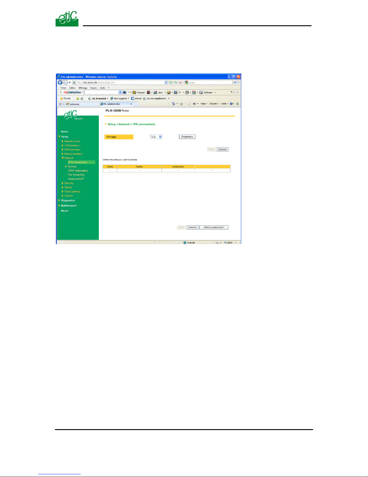
To create VPN connections between routers,
• select the « Setup» menu and then « Network» and then “VPN connections”.
Page 44
SET UP
Page 44 User guide ref 9019409-01 UMTS GPRS EDGE router ref. IPL-3G
12.2 IPSec VPN connections
12.2.1 Configuring the IPSec protocol
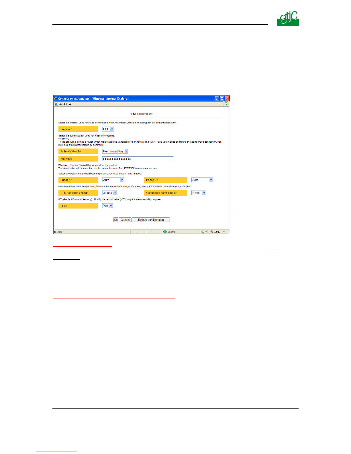
• Select the “Setup” menu, the “network” menu and then ‘VPN connections”.
• Select the “Ipsec” type of VPN,
• Click “Properties” .
“ Protocol ” parameter :
AH ((RFC2402) provides integrity, authentication, replay resistance and non-repudiation but not
encryption.
select AH, if no encryption is required or if NAT traversal is required.
ESP provides the same services plus encryption.
If ESP is selected, an encryption and an authentication protocols must be selected.
“Authentication & encryption key” parameters :
Authentication an encryption can be carried-out with a pre-shared key or a certificate.
“Pre-shared key” value :
The pre-shared key value applies to all the connections.
The maximum length of the key is 40 characters.
The same preshared key value will be used for remote users L2TP / IPSec connections.
“Certificate” value
The IPL-3G router is delivered with a certificate stored into the product in our factory.
To add a certificate, refer to the “Security” menu.
Page 45

SET UP
UMTS GPRS EDGE router ref. IPL-3G User guide ref. 9019409-01 Page 45
“Encryption and hash algorithm phase 1” & “Encryption and hash algorithm phase 2”
parameters :
That parameters allow to define the encryption and hash algorithms in use during the phase 1 of the
exchanges between the end-points (VPN set-up) and during the phase 2 (data exchange).
The default value is Auto; in that case both end-points will negotiate a common algorithm.
“DPD request period” parameters :
A DPD request (also called Keepalive message) is a message sent periodically by each end-point to
the other one to make sure that the VPN must be left active.
This parameters sets the amount of time (in seconds) between two of these requests.
“Connection death time-out” parameters :
This parameter defines the maximum amount of time (in seconds) a VPN connection will stay
established if no traffic or no DPD request message are received from the remote point.
ATTENTION : Once the parameters of the IPSEC connection have been selected, click the OK
button and then the Save button.
Page 46
SET UP
Page 46 User guide ref 9019409-01 UMTS GPRS EDGE router ref. IPL-3G
12.2.2 Configuring an outgoing IPSec connection
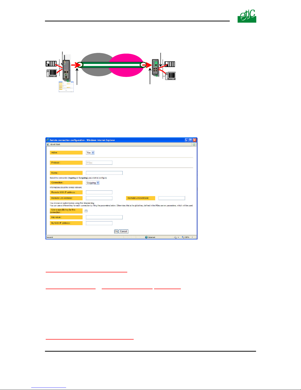
To set an outgoing VPN connection,
• Come back to the “VPN connections” screen,
• Click the “add a connection” button.
Give a name to the connection and select the “Outgoing” option.
‘Remote WAN IP address’ parameter :
Enter the IP network address and netmask assigned to the remote router over its WAN interface..
“Remote LAN address & Remote LAN netmask” parameters :
Enter the IP network address and netmask assigned to the remote LAN.
• Preshared key
If the preshared key used by the connection is the general PSK entered in the “VPN” menu, no
additional parameter has to be entered.
If a particular PSK must be used, complete the configuration of the connection as explained below.
“Unique PSK for this node” parameter :
Select that option if a particular PSK key has to be used for this connection.
VPN
INTERNET
3G
LAN IP
addr.
Outgoing
connection
WAN IP
addr.
Remote WAN
IP address
Remote LAN
IP address
Router Remote router
IP networkGPRS
Page 47

SET UP
UMTS GPRS EDGE router ref. IPL-3G User guide ref. 9019409-01 Page 47
“PSK value” parameter :
Enter the value of the PSK.
”My WAN address” parameter :
Enter the IP address of the router on the WAN interface.
• Certificate
“My subjectAlt name” & “Remote subjectAlt name” parameters :
Paste the field "SubjectAltName" of the active certificate of the router you are configuring and the one
the remote router.
Attention : For ETIC certificates, this field is the Email field
Page 48
SET UP
Page 48 User guide ref 9019409-01 UMTS GPRS EDGE router ref. IPL-3G
12.2.3 Configuring an ingoing IPSec connection
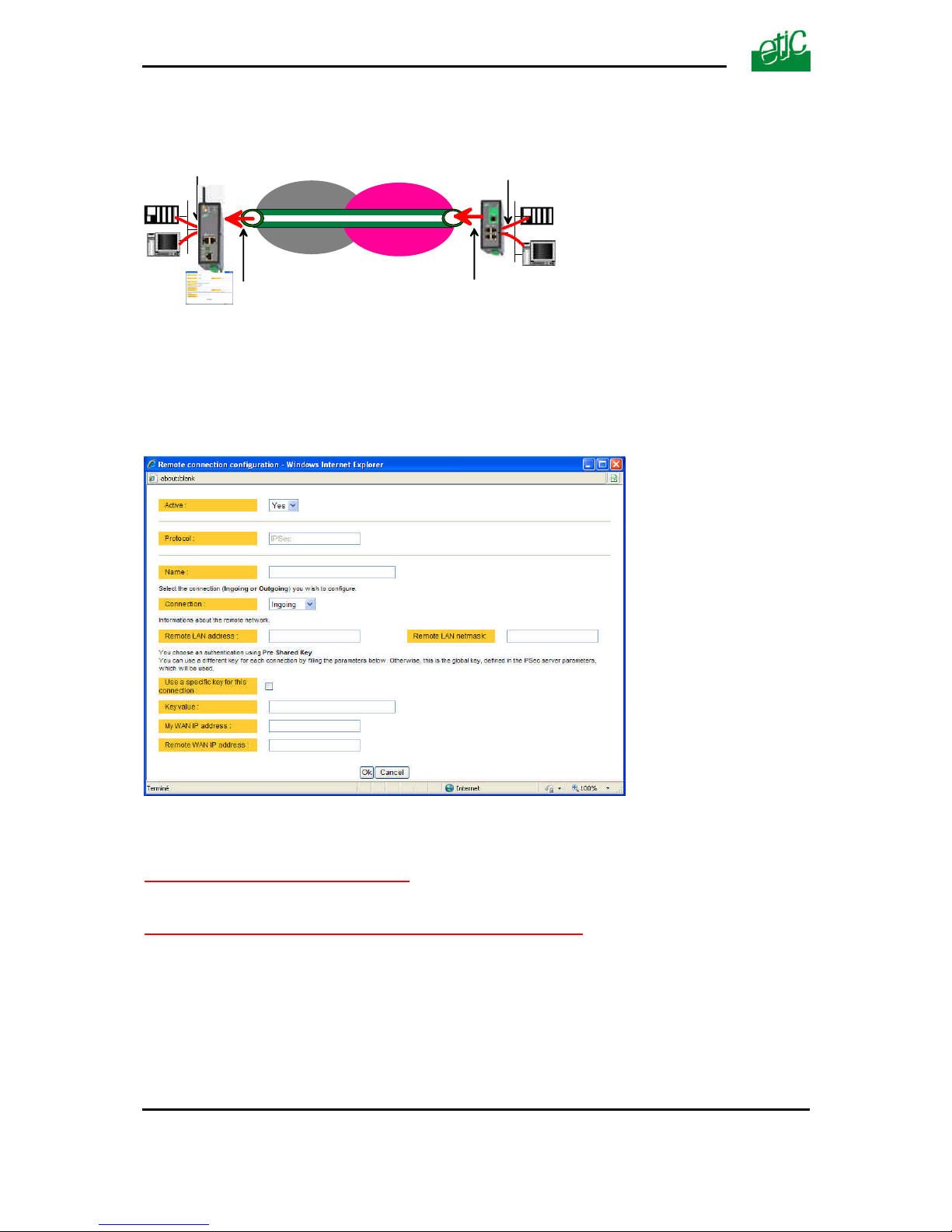
To set an ingoing VPN connection,
• Come back to the “VPN connections” screen,
• Click the “add a connection” button.
Give a name to the connection and select the “ingoing” connection direction option.
“Remote WAN IP address” parameter :
Enter the IP network address and netmask assigned to the remote router over its WAN interface.
“Remote LAN address” & “Remote LAN netmask” parameters :
Enter the IP network address and netmask assigned to the remote LAN.
• Preshared key
If the key used by the connection is the general PSK entered in the VPN menu, no additional
parameter has to be entered.
If a particular PSK must be used, carry out the configuration of the connection as explained below.
VPN
INTERNET
3G
LAN IP
addr.
Ingoing
connection
WAN IP
addr.
Remote WAN
IP address
Remote LAN
IP address
Router Remote router
IP networkGPRS
Page 49

SET UP
UMTS GPRS EDGE router ref. IPL-3G User guide ref. 9019409-01 Page 49
“Use a specific key for this connection” parameter :
If that option is not selected, the preshared key entered in the VPN configuration screen will be used
by the router.
If that option is selected, enter the specific key.
“My WAN address & Remote WAN address” parameters :
Enter the WAN IP address of the router and the WAN IP address of the remote router.
Attention : For ETIC certificates, this field is the Email field
• Certificate
“My subjectAlt name” & “Remote subjectAlt name” parameters :
Paste the field "SubjectAltName" of the active certificate of the router you are configuring and the one
the remote router.
Attention : For certificates delivered by ETIC TELECOM, this field is the Email field.
Page 50
SET UP
Page 50 User guide ref 9019409-01 UMTS GPRS EDGE router ref. IPL-3G
12.3 TLS VPN connections
12.3.1 Configuring the TLS-SSL protocol
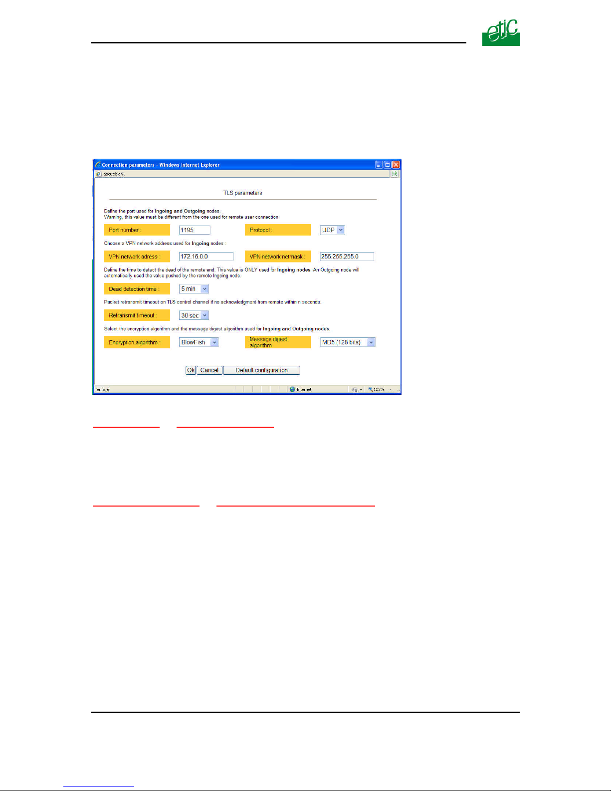
• Select the “Setup” menu, the “network” menu and then the ‘VPN connections” menu.
• Select the “TLS” VPN type and click “Properties” .
“Port number” & “protocol” parameters :
Select the port Nr and the type of level 3 protocol used to transport the TLS VPN; UDP will be
preferred.
Attention : The port number value must be different from the one used by remote users.
“VPN network address” & “VPN network netmask” parameters :
The TLS VPN server router assigns automatically an IP address to the VPN client router.
That VPN IP address must not be confused with the WAN interface IP address.
Attention :
The VPN IP network address field must be different from the WAN network IP address .
The number of VPN addresses cannot be greater than 255; the netmask cannot exceed
255.255.255.0.
Page 51

SET UP
UMTS GPRS EDGE router ref. IPL-3G User guide ref. 9019409-01 Page 51
“Connection death time-out” parameter :
This parameter defines the maximum amount of time (in seconds) a VPN connection will stay
established before being cleared if no response to the VPN control message has been received from
the remote router.
“Packet retransmit time-out” parameter:
A control message (also called Keepalive message) is sent periodically by the VPN server router to
make sure that the VPN must be left active.
This parameters sets the amount of time (in seconds) the server will wait for the response before
repeating it.
“Encryption algorithm” & “Authentication algorithm” parameter :
That parameters allow to define the encryption and hash algorithms in use.
VPN network
IP address
(default 172.16.1.0 )
TLS VPN
INTERNET
3G
LAN IP
addr.
Remote LAN IP
addr.
IP network
GPRS
Page 52
SET UP
Page 52 User guide ref 9019409-01 UMTS GPRS EDGE router ref. IPL-3G
12.3.2 Configuring an outgoing TLS connection
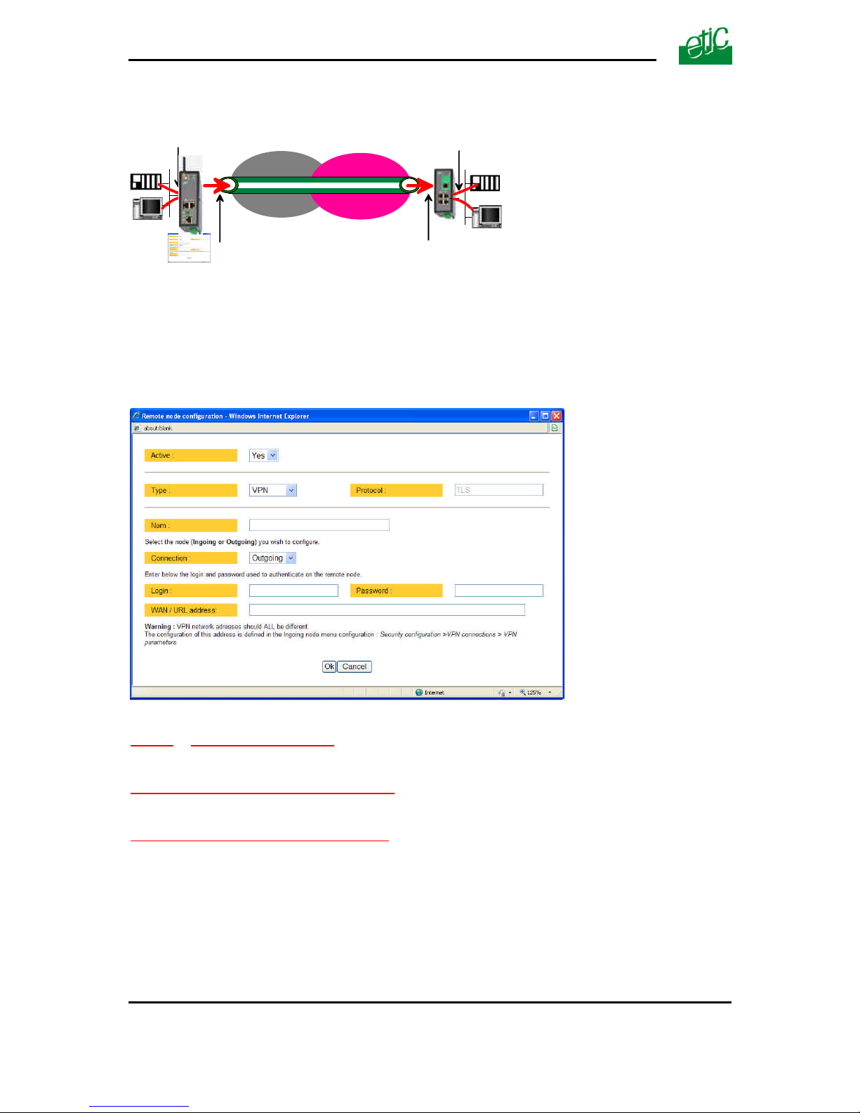
• Select the “Setup” menu, the “network” menu and then the ‘VPN connections” menu.
• Click the “add a connection” button.
• Give a name to the connection and select the “Outgoing” connection direction option.
“Login & Password” parameter:
Enter the login and password, the router will have to use to authenticate.
Remote WAN IP address / URL parameter :
Enter the IP address of the remote router or its DNS name.
“Remote WAN IP address” ” parameters :
Enter the IP network address and netmask assigned to the remote router over its WAN interface.
VPN
INTERNET
3G
LAN IP
addr.
Outgoing
connection
WAN IP
addr.
Remote WAN
IP address
Remote LAN
IP address
Router Remote router
IP networkGPRS
Page 53
SET UP
UMTS GPRS EDGE router ref. IPL-3G User guide ref. 9019409-01 Page 53
12.3.3 Configuring an ingoing TLS connection
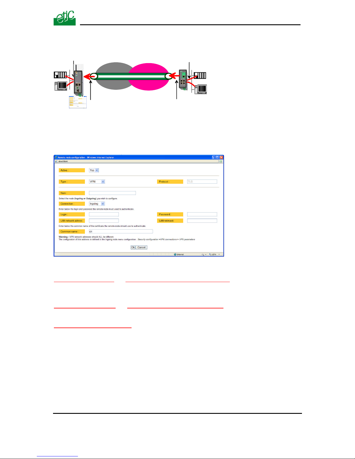
• Select the “Setup” menu, the “network” menu and then the ‘VPN connections” menu.
• Click the “add a connection” button.
Give a name to the connection and select the “ingoing” connection direction option.
“Remote router Login” & “Remote router password” ” parameters :
Enter the login and password of the remote router
The remote router has to use that login and password to authenticate.
“Remote LAN address” & “Remote LAN netmask” ” parameters :
Enter the IP network address and netmask assigned to the remote LAN.
“Common name” parameters :
Enter the remote router certificate common name.
Attention : For ETIC certificates, this field is the Email field.
VPN
INTERNET
3G
LAN IP
addr.
Ingoing
connection
WAN IP
addr.
Remote WAN
IP address
Remote LAN
IP address
Router Remote router
IP networkGPRS
Page 54
SET UP
Page 54 User guide ref 9019409-01 UMTS GPRS EDGE router ref. IPL-3G
13 Routing functions
13.1 Basic routing function
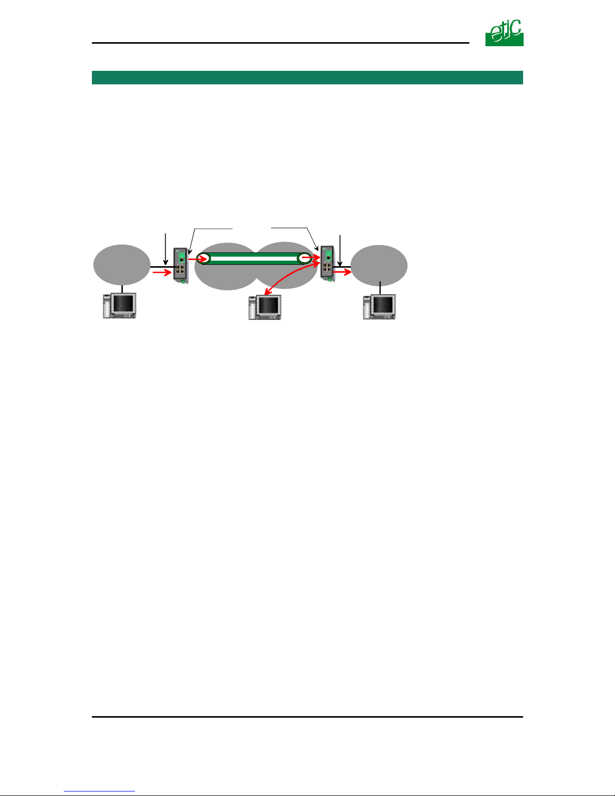
Once an iP address has been assigned to the R2 router on the LAN interface and another one on the
WAN interface (see drawing hereafter), the IPL-3G R2 router is ready to route frames …
… between devices connected to the remote LAN network like RL1, and devices connected to
the LAN network like L1 through a VPN;
… between devices connected to the WAN network like W1, and devices connected to the LAN
network like L1
Remark 1 : Firewall rules must be set to authorize WAN to LAN transfer.
Remark 2 : A default gateway address must be entered in each device of the different networks.
RL1
VPN
WAN
192.168.3.0/24
LAN
192.168.2.0/24
W1
L1
Remote WAN
192.168.4.0/24
R3 router
192.168.2.128
R2 router
192.168.3.128192.168.4.128
192.168.5.128
Remote LAN
192.168.5.0/24
Page 55
SET UP
UMTS GPRS EDGE router ref. IPL-3G User guide ref. 9019409-01 Page 55
13.2 Static routes
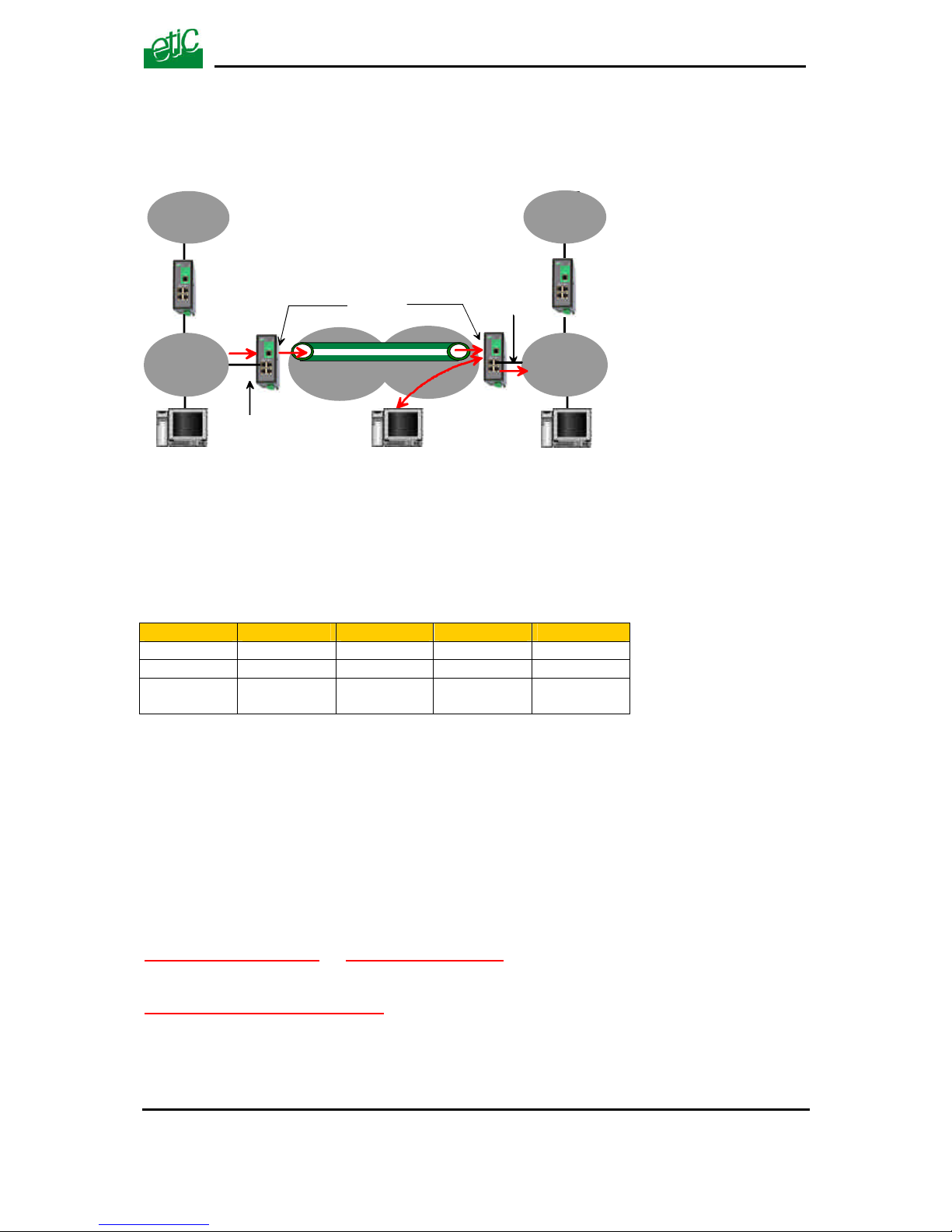
However, the router R2 is not able to route frames between a device like L1 belonging to the LAN
network and a device connected to “network 6” (see the drawing hereafter).
In that case, it is necessary to enter the route to that hidden “network 6”; that route is called a static
route.
A static route consists in a table which describes a destination network (IP address and netmask) and
the IP address of the neighbour router through which an IP packet to that destination must pass.
Router 2 static routes :
Active Route name Destination Netmask Gateway
Yes Network 6 192.168.6.0 255.255.255.0 192.168.5.1
Yes Network 1 192.168.1.0 255.255.255.0 192.168.2.1
Yes Network
Remote WAN
192.168.4.0 255.255.255.0 192.168.5.128
Remark :
It is not necessary to enter in the router R2 the static route to the WAN network nor to the remote
LAN network, that routes have been automatically created by the router respectively when the WAN
IP address has been entered and when the VPN has been configured.
To set a static route,
• Select the “Configuration” menu, the “network” menu the “Routing” menu and then “Static
routes”.
• click the “Add a route” button.
“Destination IP address” & “netmask” parameters :
Enter the destination network IP address and netmask.
“Gateway IP address” parameters :
Enter the Ip address of the gateway through which the IP packets intended for that network must
pass.
Network 6
192.168.6.0
network 1
192.168.1.0
192.168.6.24
192.168.1.24
R1 routerR4 router
192.168.5.1 192.168.2.1
192.168.2.128
RL1
VPN
W1
L1
R3 router
192.168.5.128
R2 router
192.168.3.128192.168.4.128
Remote WAN
192.168.4.0/24
WAN
192.168.3.0/24
Remote LAN
192.168.5.0/24
LAN
192.168.2.0/24
Page 56

SET UP
Page 56 User guide ref 9019409-01 UMTS GPRS EDGE router ref. IPL-3G
13.3 RIP protocol
RIP (Routing Information Protocol) is a routing protocol which enables each router belonging to a
network to acquire the routes to any subnet.
The principle is as follows :
Routing table
Each router holds a routing table.
Each entry of the table consists in the destination subnet address and the adjacent router address
leading to that subnet.
Routing table broadcasting :
Each router broadcasts its table.
Routing table update :
Each router updates its own table using the tables received from the other ones.
To enable RIP,
• select the « Setup» menu, the “Routing” menu and then the “RIP” menu».
• Select the ‘Enable RIP on LAN interface” and the “Enable RIP on WAN interface” options.
Page 57
SET UP
UMTS GPRS EDGE router ref. IPL-3G User guide ref. 9019409-01 Page 57
14 Address and port translation
The IPL-3G provides the capability to replace the original source IP address and the destination
port and IP address in particular situations.
14.1 Port forwarding
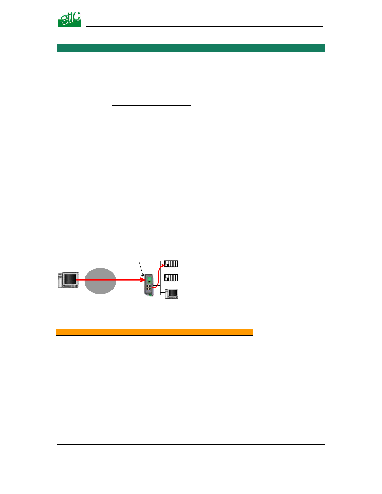
Port forwarding consists in transferring the IP frames addressed to the IPL-3G antenna IP address
(WAN IP address) at a particular port number, to a particular device connected to the LAN
interface.
The transfer criteria is the port number; the port number is used as an additional address field.
When a frame is addressed to the IPL-3G router with a particular registered port, it is transferred to
a particular device connected to the LAN interface.
Example :
Let us suppose the PC named “W1” connected to the Internet has to send frames to the device
PLC1 connected to one Ethernet port of the IPL-3G router.
The solution can be to use the Port forwarding function :
When W1 needs to transmit frames to PLC1, it addresses the frames to the IPL-3G router on a
chosen and agreed port.
The router checks the frame, replaces the destination address by the IP address of the device on the
LAN interface, and eventually changes the port number.
The port forwarding rule will be
Internet / WAN LAN translation
Service Device Service
102 192.168.0.15 102
502 192.168.0.16 502
80 192.168.0.17 80
To set the Port forwarding function,
• select the “network” menu and then the “Port forwarding” menu.
• Click “Add a DNAT” rule.
PLC1 192.168.0.15
TCP : 102
PLC2 192.168.0.16
TCP : 502
PC 192.168.0.17
TCP : 80
62.10.10.7
TCP : 102
WAN IP addr. :
62.10.10.7
WAN
network
W1
Page 58
SET UP
Page 58 User guide ref 9019409-01 UMTS GPRS EDGE router ref. IPL-3G
14.2 Advanced network address and port translation
14.2.1 Principle
This function is available in IPL-3G-1400B, IPL-3G-1201B, IPL-3G-1220B, IPL-3G-1230B routers
only.
That function consists in replacing the source port and IP address or the destination port and IP
address of particular frames received by the router on its interfaces according to configured rules.
It applies to all the frames received by the router on any of its two interfaces except to the IP packets
contained in a remote user PPTP or TLS connection.
It applies as well to frames the destination address of which is the IPL-3G router itself or to frames
the destination IP address is a device belonging to the LAN subnet, or to the WAN subnet or to
another network.
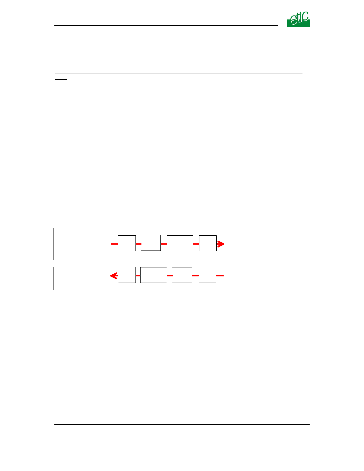
One brings out
the DNAT function which consists in replacing the destination port and IP address.
the SNAT function which consists in replacing the source IP address.
Because the DNAT and SNAT functions modify the IP addresses of the IP packets processed by the
IPL-3G router, and because the firewall filters that frames, it is very important to understand in which
order that different functions are carried out.
Direction
WAN to LAN
LAN to WAN
DNAT
FIREWALL
SNAT
WAN LAN
Router
LAN
SNAT
DNAT
WAN
FIREWALL
Router
Page 59
SET UP
UMTS GPRS EDGE router ref. IPL-3G User guide ref. 9019409-01 Page 59
14.2.2 Configuration
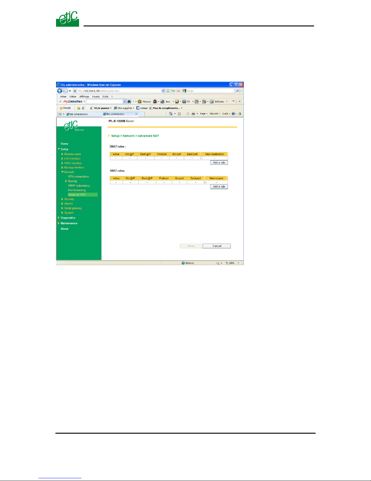
To set the advanced address translation functions,
• select the “Setup” menu, “Network” , and then the “Advanced NAT” menu.
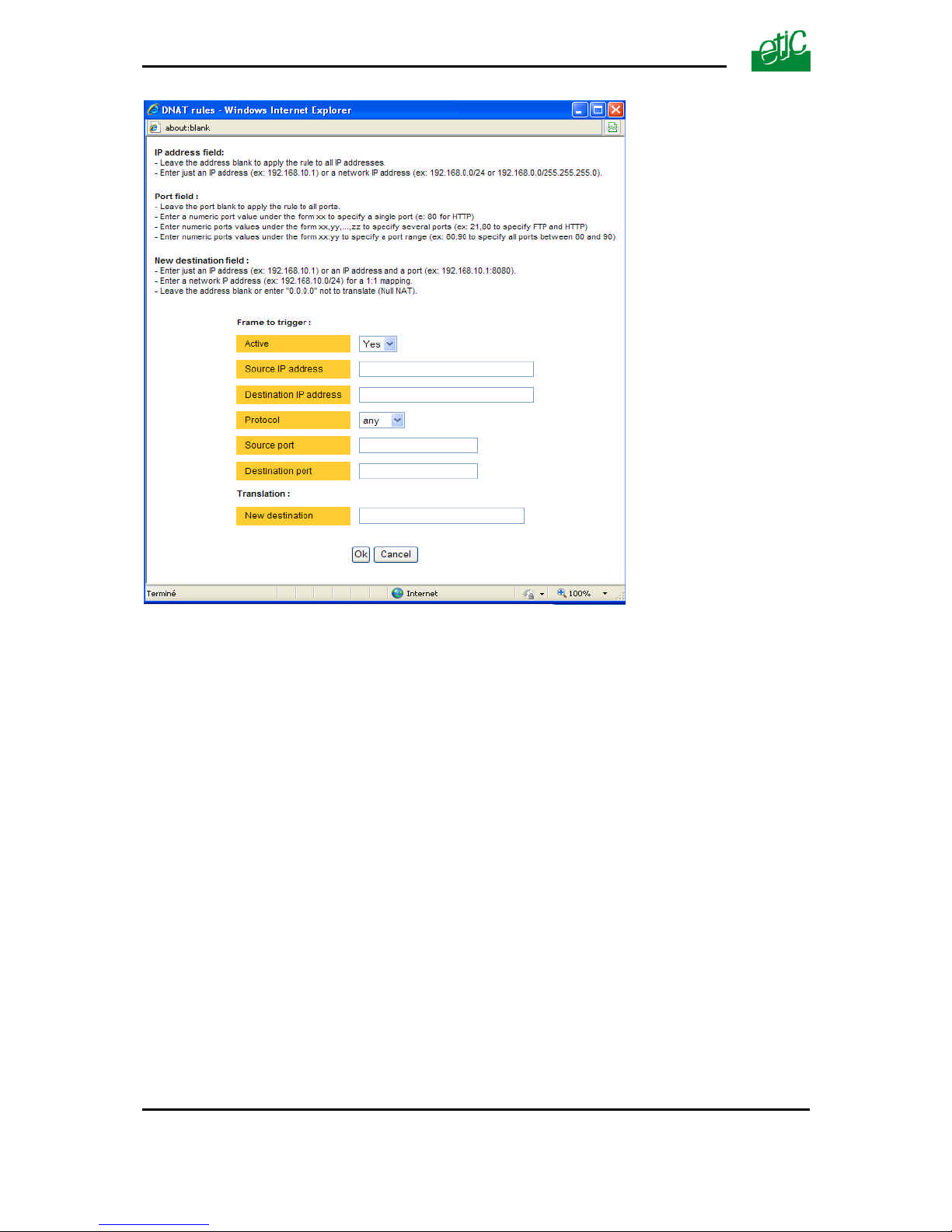
To create a new DNAT rule
• Click “Add a DNAT” rule.
• Select “Yes” to enable the rule.
• Enter the replacement criterion :
Source IP address & Destination IP address.
Protocol (TCP, UDP, …)
Source port & Destination port
• Enter the new destination port number and IP address.
Page 60
SET UP
Page 60 User guide ref 9019409-01 UMTS GPRS EDGE router ref. IPL-3G
Page 61
SET UP
UMTS GPRS EDGE router ref. IPL-3G User guide ref. 9019409-01 Page 61
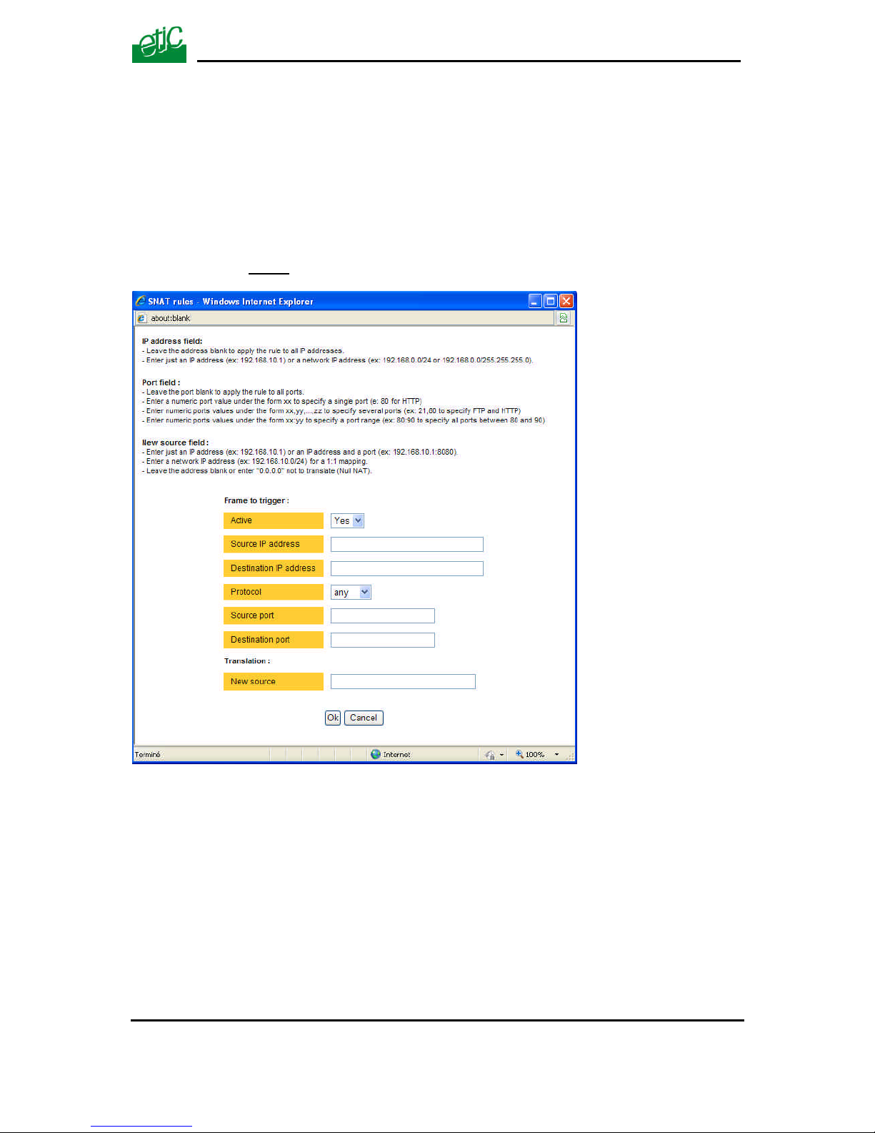
To replace the source IP address & destination port
• Click “Add a SNAT” rule.
• Select “Yes” to enable the rule.
• Enter the replacement criterions :
Source & Destination IP address.
Protocol (TCP, UDP, …)
Source & Destination port
• Enter the new source IP address.
Page 62

SET UP
Page 62 User guide ref 9019409-01 UMTS GPRS EDGE router ref. IPL-3G
15 VRRP redundancy
That function is available only in IPL-3G-1400B, IPL-3G-1201B, IPL-3G-1220B, IPL-3G-1230B
routers
15.1 Principle
VRRP is a protocol designed to increase the availability of the default gateway of a subnet.
Thanks to VRRP, a group of two or more routers can service the hosts of one subnet instead of only
one usually; only one router of that group actually routes frames; if it fails another one of the group
takes its place.
The routers belonging to a VRRP group must be connected to the same Ethernet segment.
VRRP works as follows :
An usual IP address is assigned to each router of the group.
An additional and common IP address, called the virtual IP address is assigned to all the routers of
the group. This virtual address is the address which must be stored as the default gateway address in
all the host devices belonging to the subnet.
A priority index is assigned to each router of the group. Using that index, the routers of the group can
elect a master router; the master router is the one which has the greatest priority code. The other
routers are the backup routers.
The master router is the only one to answer to the ARP requests and route actually frames. It uses
the virtual IP address and the virtual MAC address If that option has been selected.
In case of failure of the master router, another master router is elected. It replaces the router in
failure. It will use the same virtual IP address and the virtual MAC address as the previous master
router.
The IPL-3G router manages that protocol as well on the LAN and on the WAN interface.
15.2 Configuring VRRP on the LAN interface
To enable and configure VRRP,
• select the “Setup” menu, the “network” menu and then the “VRRP” menu.
«Enable VRRP on the LAN interface» parameters :
Tick that checkbox to enable VRRP on the LAN interface.
«VRRP Id (1-255)» parameter:
Assign an identity code to the routers group between 1 and 255.
The same identity code must be assigned to all the routers of the group.
«Virtual IP address» parameter :
Enter the IP address the elected master router will use to answer to ARP requests.
«Priority (1-255)» parameter :
Assign a priority index to the router
Page 63

SET UP
UMTS GPRS EDGE router ref. IPL-3G User guide ref. 9019409-01 Page 63
The router which has the greatest index will become the master router.
«Use a virtual MAC address» parameter :
A virtual MAC address can be associated to the virtual IP address.
If that option is selected, the elected master router will answer to ARP requests by using that virtual
MAC address.
That MAC address is 00-00-5E-00-01-XX, where XX is the VRRP Id of the group coded in
hexadecimal.
15.3 Configuring VRRP on the WAN interface
To enable and configure VRRP,
• select the “Setup” menu, the “network” menu and then the “VRRP” menu.
«Enable VRRP on the WAN interface» parameter :
Tick that checkbox to enable VRRP on the LAN interface.
«VRRP Id (1-255)» parameter :
Assign an identity code to the routers group between 1 and 255.
The same identity code must be assigned to all the routers of the group.
«Virtual IP address» parameter :
Enter the IP address the elected master router will use to answer to ARP requests.
«Priority (1-255)» parameter :
Assign a priority index to the router
The router which has the greatest index will become the master router.
«Use a virtual MAC address» parameter :
A virtual MAC address can be associated to the virtual IP address.
If that option is selected, the elected master router will answer to ARP requests by using that virtual
MAC address.
That MAC address is 00-00-5E-00-01-XX, where XX is the VRRP Id of the group coded in
hexadecimal.
Page 64

SET UP
Page 64 User guide ref 9019409-01 UMTS GPRS EDGE router ref. IPL-3G
16 Remote users connections service
The IPL-3G provides a full remote user connection function called RAS :
• The remote user authenticates using the login, password and eventually a certificate; the router
accepts the connection only if the remote user belongs to the user list.
• Individual access rights are automatically allocated to the remote user.
• An IP address belonging to the LAN network is automatically assigned to the remote PC.
• Data are encrypted (TLS and L2TP / IPSec only).
• The connection is logged.
• Moreover, the IPL-3G is compatible with the M2Me_Connect service when setting a direct
connection is not possible.
To setup the remote user connection service, the following steps must be carried out :
• Step 1 :
Configure a PPTP or TLS or L2TP connection
or select the M2Me_Connect service configuration menu.
• Step 2 :
Complete the user list
• Step 3 ::
Define the firewall rules to limit the rights of the remote users
Page 65

SET UP
UMTS GPRS EDGE router ref. IPL-3G User guide ref. 9019409-01 Page 65
17 Remote users connections
17.1 Principles
A remote user connection is a tunnel set between a remote PC and a router providing the RAS
function (Remote Access Service), like the IPL-3G.
A remote user connection provides security and simplicity advantages :
• The remote user is identified with a login in and password or eventually a certificate.
• The data is encrypted (TLS or L2TP).
• An IP address belonging to the local network is automatically assigned to the remote user’s PC.
The IPL-3G manages PPTP and TLS or L2TP remote connections.
Only one type can be selected. It will apply to all the remote users connections.
A PPTP is the simplest type of remote user connection; data is not encrypted.
The remote user can be identified only with a login and password.
A TLS connection provides encryption; moreover; the remote user can be identified with a log in and
password and with a certificate if necessary.
Page 66
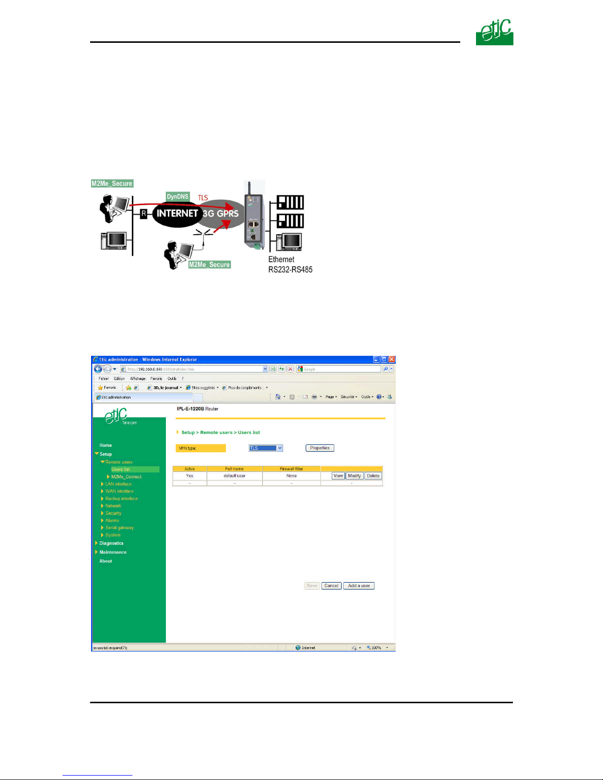
SET UP
Page 66 User guide ref 9019409-01 UMTS GPRS EDGE router ref. IPL-3G
17.2 Configuring a TLS connection
The M2Me_Secure software provided by ETIC TELECOM is a Windows TLS client software.
Installed on a PC running Windows XP or Seven, M2Me_Secure makes TLS connections from a
remote PC to the IPL-3G easy; moreover it includes a connection book in such a way one just need a
click to connect to a remote site.
We describe hereafter how to configure the router and the M2Me_Secure software to set a TLS VPN
between both.
Step 1 : Router configuration
To configure a remote user TLS connection,
• select the “Setup” menu, the “Remote users” menu and then the “User list” menu.
• Select the VPN type “ TLS”.
• Click the “Properties” button and set the parameters.
Page 67

SET UP
UMTS GPRS EDGE router ref. IPL-3G User guide ref. 9019409-01 Page 67
”Port number” & “Protocol” :
Select the port Nr and the type of level 3 protocol used to transport the TLS VPN; UDP will be
preferred.
Attention :
The selected port number assigned to the remote users connections must be different from the one
used for VPN connections between routers if such VPN connections have been configured.
“Remote Users authentication” parameters :
Authentication an encryption can be carried-out with a pre-shared key or a certificate.
If the “Login/password” is selected, the remote user is authenticated with a login and a
password.
If the “Login/password and Certificate” value is selected, the remote PC is authenticated with
the certificate and the user with a login and password. In that case, the PC certificate must be
stored in the user list.
«Encryption algorithm» & «Message digest algorithm» parameters :
Leave the default values.
Step 2 : Configure the M2Me_Secure software
For detailed information, report to the M2Me_Secure manual.
• Click « Menu » and then « New site ». The Site configuration window is displayed.
• Select the « General » tab and enter a site name.
• Select the « Connection » tab; select the option “That site can be reached through the Internet.
• In the field « Host name or IP address », select the router IP address or DynDNS name or DNS
name.
• Select the « Advanced tab » ; select the level 3 protocol (UDP or TCP), the port number and the
encryption algorithm.
These parameters must have the same values must in the PC and in the router.
Page 68
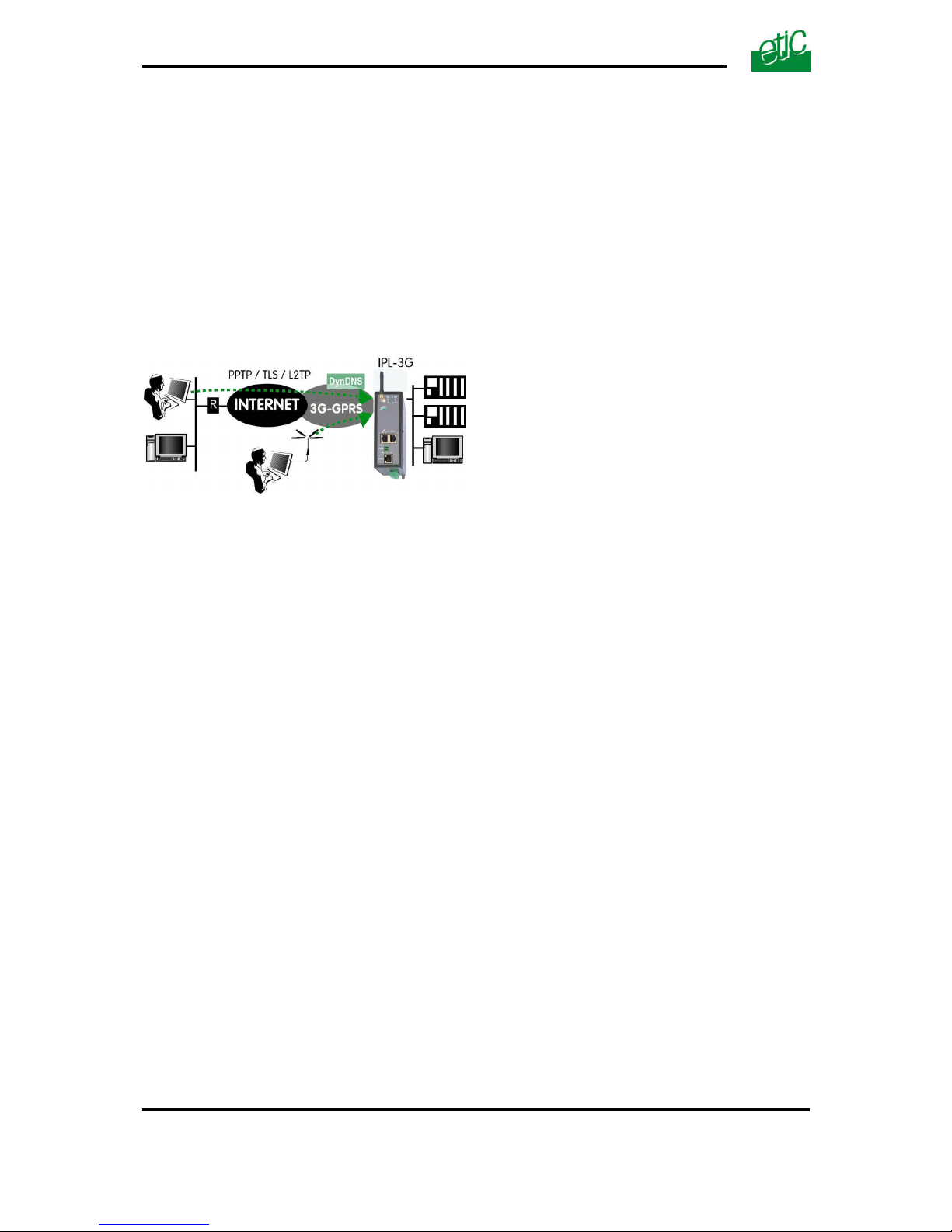
SET UP
Page 68 User guide ref 9019409-01 UMTS GPRS EDGE router ref. IPL-3G
17.3 Configuring a PPTP connection
We describe hereafter how to configure the router and the PC to set a PPTP remote user connection
between them.
Step 1 : Router configuration
• select the “Setup” menu, the “Remote users” menu and then the “User list” menu.
• Select the VPN type “ PPTP”.
Remark : The “properties” button allows to modify the authentication protocol; leave the default
configuration if the PPTP client is a PC running Windows.
Step 2 : Set up a PPTP connection on the PC side.
Page 69
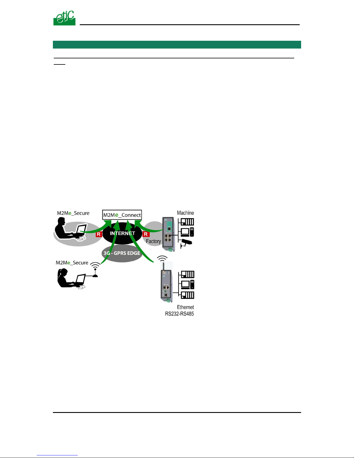
SET UP
UMTS GPRS EDGE router ref. IPL-3G User guide ref. 9019409-01 Page 69
18 M2Me_Connect service
This function is available in IPL-3G-1400B, IPL-3G-1201B, IPL-3G-1220B, IPL-3G-1230B routers
only.
18.1 Overview
The M2Me_Connect service simplifies the connection of a remote PC to a machine through the
Internet.
It provides a solution when a direct PPTP or TLS connection described before shows itself impossible
in particular when the IP address assigned by the provider to the IPL-3G antenna (WAN interface) is
not a public IP address.
The M2Me_Connect service solves that difficulty :
The PC does not connect directly to the IPL-3G; both the PC and the router connect to the
“M2Me_Connect” service.
Once both parties have been authenticated by the M2Me_Connect service with their own certificate,
a TLS VPN is set from end to end from the PC to the IPL-3G router.
The remote user identity is checked by the router to verify he or she belongs to the user list stored in
the IPL-3G router.
Finally, individual access rights are assigned to the remote user depending on his or her identity.
Page 70

SET UP
Page 70 User guide ref 9019409-01 UMTS GPRS EDGE router ref. IPL-3G
18.2 Configuring a M2Me_Connect connection
Step 1 : Router configuration
• Select the « Setup» menu, the « Remote users » menu, the “M2Me_Connect” menu, and
then the “Connection” menu.
« Activate » parameter:
Select the checkbox
“TCP ports” and “UDP ports” parameters :
Select the protocol (UDP and or TCP) and the ports numbers the router must check to set a
connection to the M2Me_Connect service.
We advise to select only the TCP protocol because providers sometimes forbid UDP to avoid
unsolicited frames coming from the internet to the antenna of the router.
• Test the connection
Click the “Control” menu, and press the “connect now” button.
Go to the ”Diagnostic” menu, “Network status” menu and then “M2Me”.
When the connection between the router and the M2Me_Connect service is established, the port
number and protocol are displayed.
• Deselect the ports numbers needlessly selected
If too many ports have been selected, the connection delay may be long; it is why, we advise to
unselect all the ports except the one which has finally been successful.
Step 2 : M2Me_Secure software configuration (PC side)
• Click « Menu » and then « New site ». The Site configuration window is displayed.
• Select the « General » tab and enter a site name.
• Select the « Connection » tab; select the option “That site can be reached through the Internet
and the “M2Me_Connect” option.
• Enter the product key of the router; it can be pasted from the “About” menu of the router.
Page 71
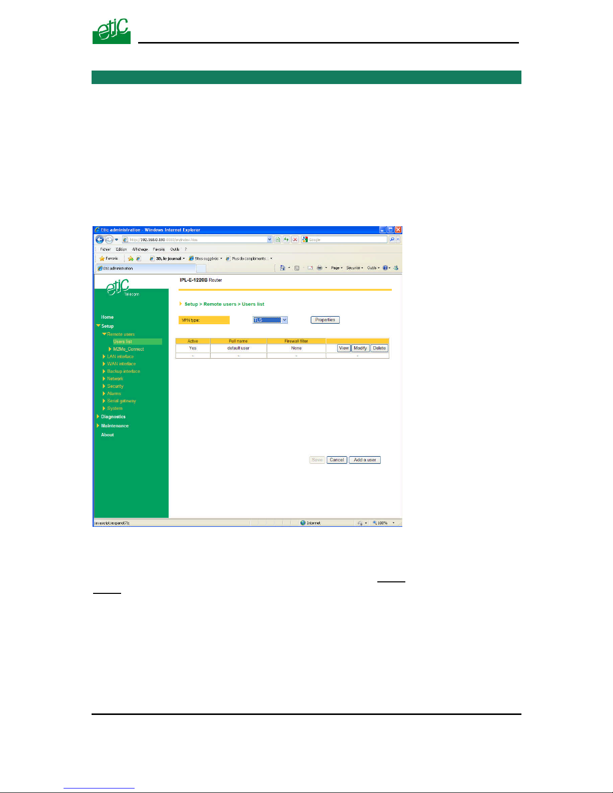
SET UP
UMTS GPRS EDGE router ref. IPL-3G User guide ref. 9019409-01 Page 71
19 Users list
Storing at least an authorized user in the users list is necessary if a remote user wishes to connect to
the IPL-3G with a PPTP or a TLS or a L2TP/IPSec remote user connection.
The users list registers 25 authorised remote users forms.
Each user form stores the identity of the user (Login and password), his email address to send alarm
emails and the filter assigned to him.
To display the user list,
• select the “Setup” menu, the “Remote users” menu and then the “User list” menu.
Attention :
Coming from factory, a default user is registered; his login is admin and the password is also
admin. After the test phase, we advise to modify these login and password.
Page 72
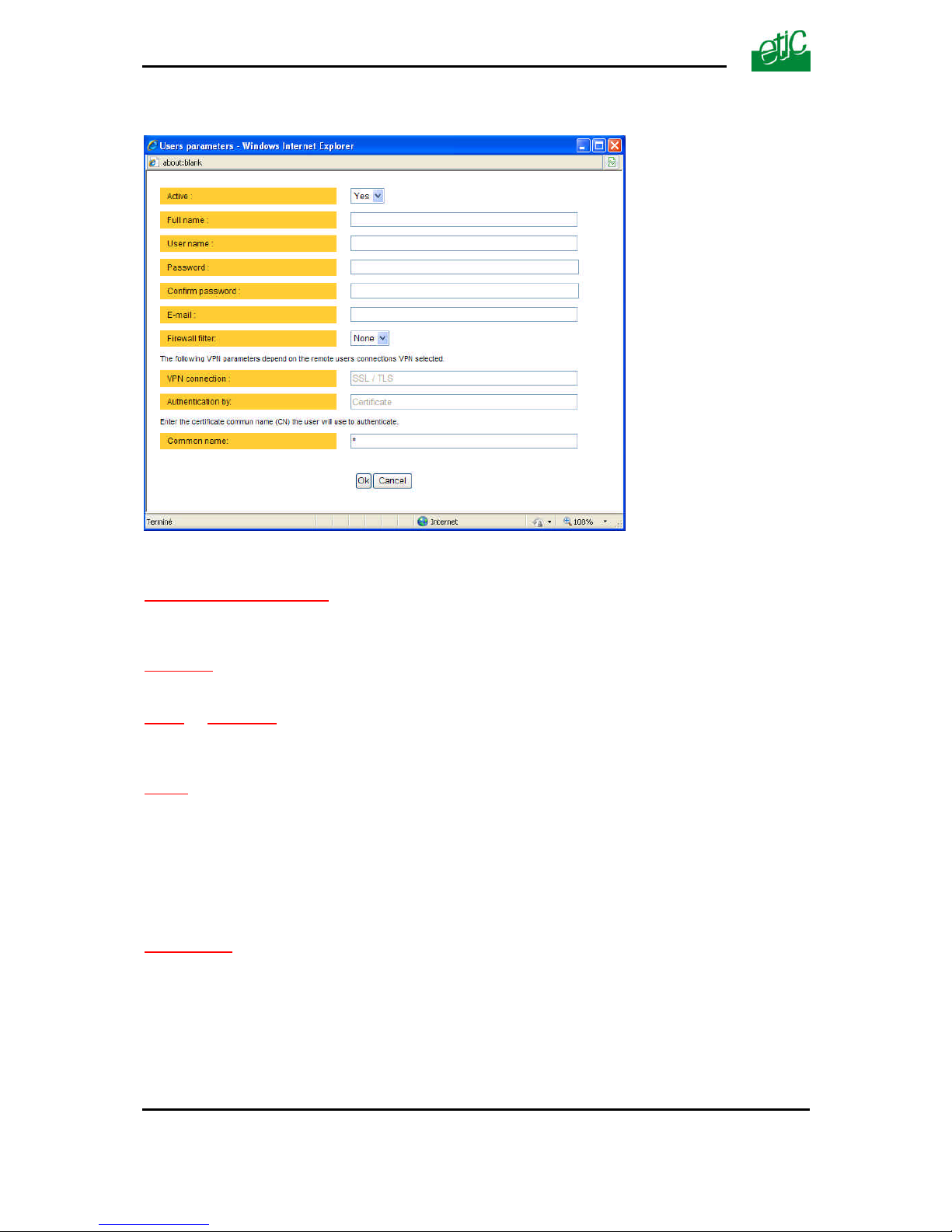
SET UP
Page 72 User guide ref 9019409-01 UMTS GPRS EDGE router ref. IPL-3G
To add a user form
• Click the “add a user ” button
“ Active (value Yes or NO)” :
Select “No” if you want to prevent the user to access the network.
Select “yes” to authorize the user to access the network.
Full name :
It is the name displayed in the user list.
Login & password
The login and the password will have to be entered by each user at the beginning of the remote
connection.
E-mail :
The IPL-3G will send an email to that address in two situations :
Alarm email : the IPL-3G sends an alarm email to the defined user If the input 1 is closed or opened (if
that option has been set).
Internet connection email : Once connected to the Internet, the IPL-3G will send to the demanding
user an email containing the dynamic IP @ assigned to the IPL-3G by the provider. (See
OPERATION chapter).
Firewall filter :
Select a filter in the list.
A filter defines a domain of the local network.
Thus, once assigned to a user, a filter limits his or her access rights.
Page 73
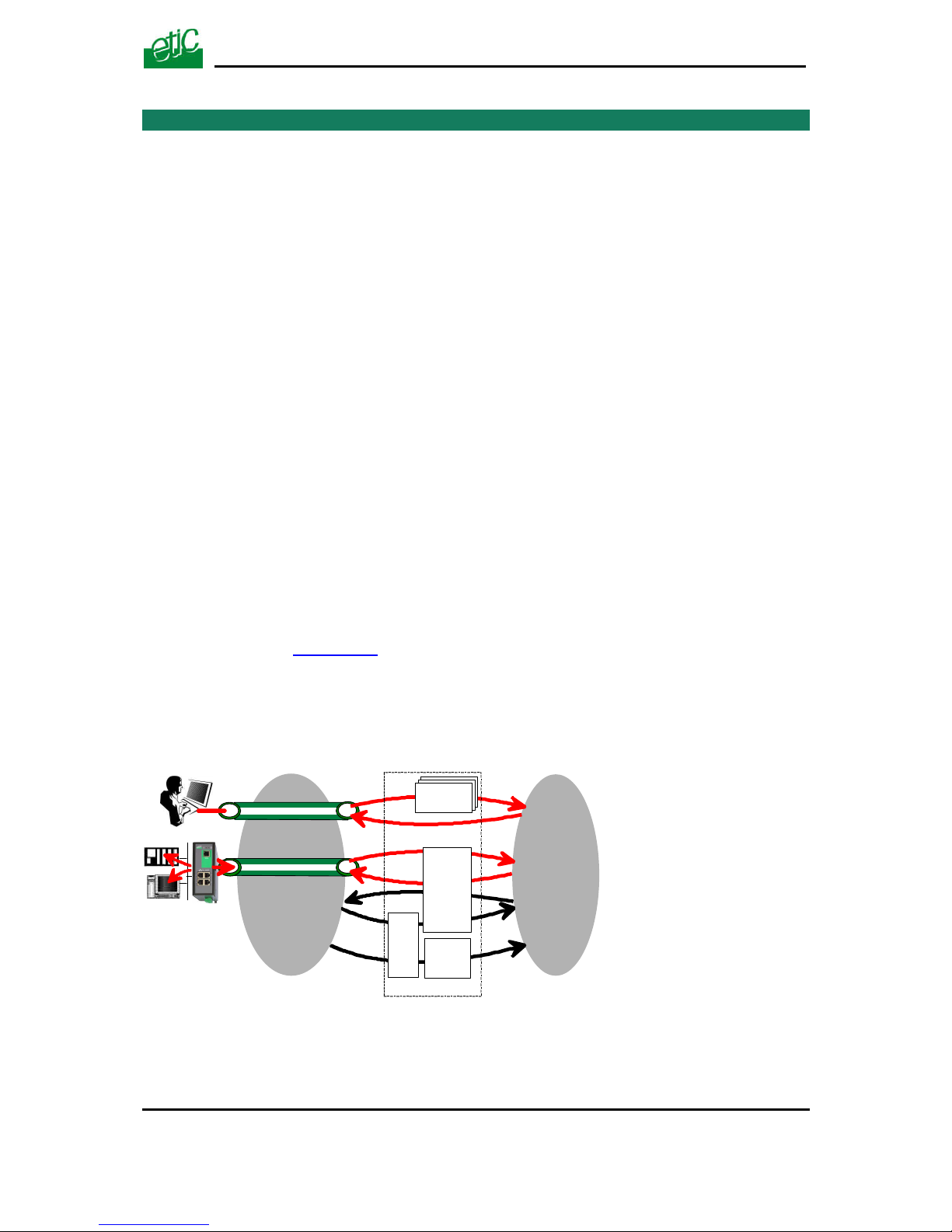
SET UP
UMTS GPRS EDGE router ref. IPL-3G User guide ref. 9019409-01 Page 73
20 Firewall
20.1 Overview
The firewall filters IP packets between the WAN and the LAN interface of the IPL-3G router. It is
divided in 3 particular filters :
• The remote users filters
The function of the remote users filters is to limit the IP domain an authenticated remote user can
reach when he connects to the IPL-3G router through the Internet.
The remote users filters filter the destination IP address and port number of the IP packets included
inside a PPTP or TLS or L2TP remote user connection.
Thus the IP addresses checked by the remote users filters are LAN IP addresses.
25 remote users filters can be created and assigned individually to each of the users declared in the
user list.
The source IP address of the packets is not checked by the remote users filters because the filters
apply to the remote users connections according the login and password of the remote user checked
when the remote user connection is set.
• The main filter
It filters IP packets whether carried inside one of the VPNs or outside a VPN.
The main filter checks source and destination IP addresses and the source and destination ports.
The main filter does not check the IP packets included in a remote user connection. That packets are
checked by the remote users filter.
The main filter does not check the IP packets defined in the “Port forwarding” table. That packed are directly forwarded
to the defined device (see Port forwarding).
• The deny of service filter is made to usual attacks coming from the Internet. That filter
cannot be configured.
The firewall of the IPL-3G firewall can thus be represented by the drawing hereafter :
VPN between routers
WAN
LAN
Users
filters
Main
filter
FIRE-WALL
DoS
filter
Port
forwarding
Remote user connection
Page 74

SET UP
Page 74 User guide ref 9019409-01 UMTS GPRS EDGE router ref. IPL-3G
20.2 Main filter
The main filter applies to all the IP packets except to the ones included in remote users connections.
To recognize a TLS remote user connection, the router detects the port number.
20.2.1 Main filter Overview
• Main filter structure
For a better organisation, the main filter is divided in two tables; both having the same structure.
The “VPN” filter : It filter the packets transmitted inside the VPNs.
The “WAN” filter : It filters the packets transmitted outside the VPNs
Each of that two filters is made of
a filter policy
and
a filter table each line of which is a filter rule
• Main filter default policy
The default policy is the decision which will be applied if a packet does not match any of the rules of
the filter.
The WAN to LAN and the LAN to WAN traffic are regarded separately because the decision can be
opposite for a packet coming from the WAN or coming from the LAN :
WAN to LAN : The default policy can be “Accept” or “drop”.
LAN to WAN : The default policy can also be “Accept” or “drop”.
For instance, if the default policy assigned the WAN to LAN traffic is “drop”, it means that an IP
packet which does not match any of the rules of the main filter will be rejected.
• Main filter table
The main filter is a table, each line being a rule.
Each rule of the filter is composed a several fields which defines a particular data flow and another
field which is called the action field.
The fields which define the data flow are :
Direction (« WAN to LAN » or « LAN to WAN »),
Protocol (TCP, UDP…),
IP@ & port number, source & destination.
The Action field can take two values
Accept : To authorize the data flow to be forwarded to the router interface.
Drop : To drop the packet which matches the rule.
• How does the main filters works
When the firewall receives a packet, it checks if it matches the first rule..
If it does, the decision is applied to the packet according to the “Action” field.
If it does not, the firewall checks if it matches the second rule; and so on.
Page 75

SET UP
UMTS GPRS EDGE router ref. IPL-3G User guide ref. 9019409-01 Page 75
If the packet does not match any of the rules of the table, the default policy is applied to the packet (drop or reject).
Page 76
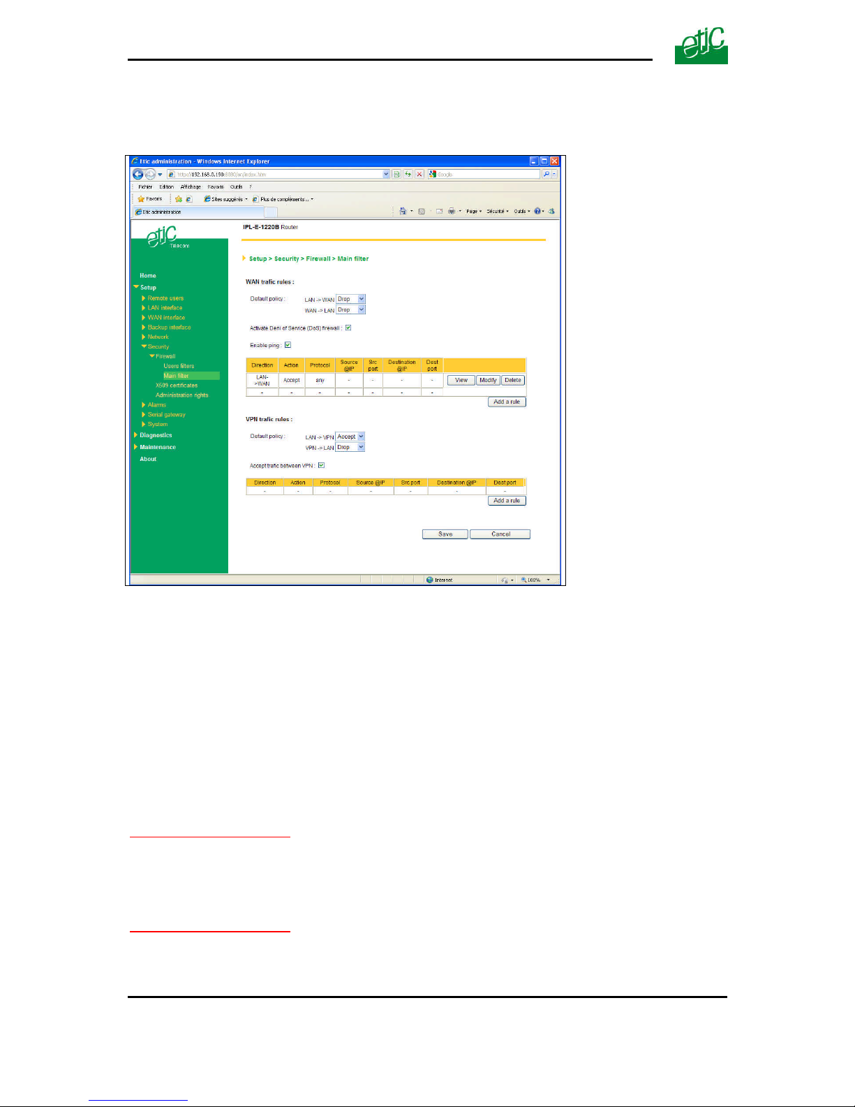
SET UP
Page 76 User guide ref 9019409-01 UMTS GPRS EDGE router ref. IPL-3G
20.2.2 Configuring the main filter
Select the “Security” menu and then “Firewall” and “Main filter”.
The “Main filter” page is divided in two parts :
WAN traffic rules :
The first part, entitled “WAN” traffic rules, is made to define how the IP packets not carried in a VPN,
have to be filtered.
VPN traffic rules :
The second part, entitled “VPN traffic rules” allows to define how the IP packets carried inside the
VPNs have to be filtered.
Configure successively the WAN traffic rules using the same method.
Step 1 : Select the default policy
“LAN to WAN” parameter :
That parameter sets what the filter will decide if an IP packet coming from the LAN does not match
any f the rules of the filter :
If the value “Accept” is selected, the IP packet will be transmitted to the VPN.
If the value “Drop” is selected, the IP packet will be rejected.
“WAN to LAN” parameter :
That parameter sets what the filter will decide if an IP packet coming from the WAN does not match
any f the rules of the filter :
If the value “Accept” is selected, the IP packet will be transmitted to the LAN.
If the value “Drop” is selected, the IP packet will be rejected.
Page 77

SET UP
UMTS GPRS EDGE router ref. IPL-3G User guide ref. 9019409-01 Page 77
The cautious default policy is to choose the value “Drop”; at the opposite, if the value “Accept”
is selected, a frame which does not match any of the rules of the filter is transmitted.
Step 2 : Add a rule to the filter
Click the “add a rule” button.
“Direction” parameter :
Select the direction of the data flow to which the rule applies.
“Action” parameter :
Select the value “Accept” if the IP packet has to be transmitted in the selected direction.
Select the value “Drop” if the IP packet has to be rejected.
“Protocol” parameter :
Select the level 3 protocol concerned.
“Source IP address” & “Source port” parameters :
Enter the value of the source IP address and the source port number.
It is possible to enter a range of source IP addresses and not a single IP address by selecting a
netmask value from 1 to 32; It is the number of binary 1 of the netmask; for instance, the value 24
means 255.255.255.0; the value 16 means 255.255.0.0.
”Destination IP address” & “destination port” parameters :
Enter the value of the destination IP address and the destination port number. Select the netmask
value.
20.3 Remote users filters
A remote user filter applies to the IP packets received inside a remote user connection.
25 remote user filters can be configured and assigned individually to each of the users declared in the
user list.
A remote user filter is a table of destination port numbers and IP addresses belonging to the LAN
network.
Once a remote user is connected to the IPL-3G router, the router applies the filter assigned to him
(see the remote user form).
According to his identity (Login and password, he will thus only access to the IP domain defined by
the filter.
Example :
Filter name : Access to the device PLC1 (html and modbus)
Filter policy : All is forbidden except what we specify
Rules list
Action Device Service
Allow PLC1 192.168.0.12 80
Allow PLC1 192.168.0.12 Modbus 502
A filter must be assigned at least to one user to become enabled.
Page 78
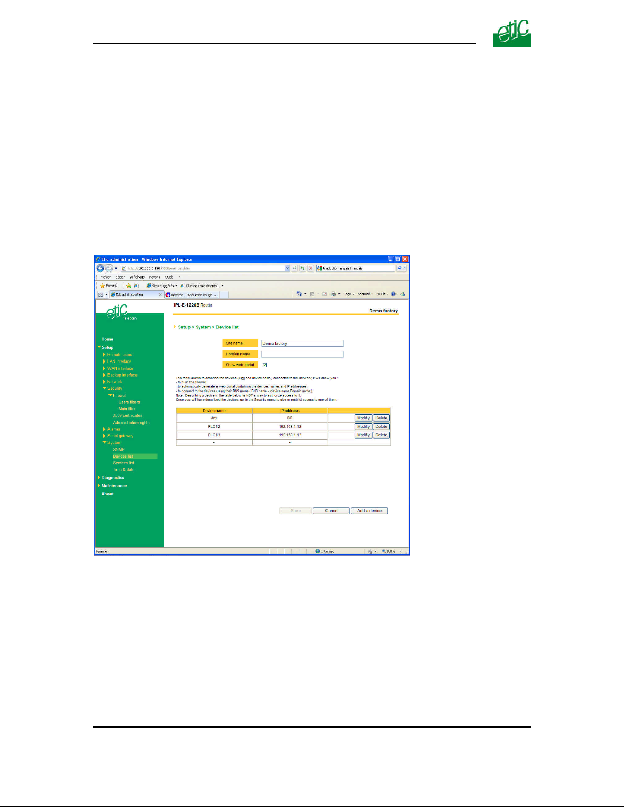
SET UP
Page 78 User guide ref 9019409-01 UMTS GPRS EDGE router ref. IPL-3G
Step 1 : Complete, if necessary, the list of services
Remark : The main services (html, ftp, modbus) are available from factory; for that reason, most of
the time, that step can be skipped.
• Select the menu “system” and then “service list” The list of TCP ports is displayed.
• Click « add a service ».
• Enter the label of that the new service, assign a protocol (udp, tcp, icmp) and a port number.
• Save. The list is updated.
Step 2 : Enter the list of devices of the LAN network
• Select the «System» menu, then «Devices list».
The list of the devices of the LAN network is displayed.
• Click « add a device ».
• Assign a label and an IP address to the device and click OK.
Page 79
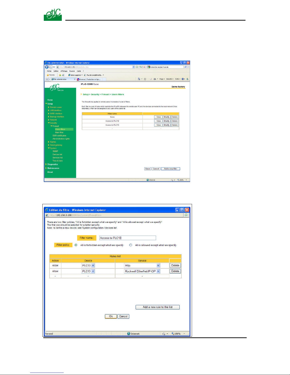
SET UP
UMTS GPRS EDGE router ref. IPL-3G User guide ref. 9019409-01 Page 79
Step 3 : Build a remote user filter
• Select the « security» menu, then « firewall» and then «Filter list» The users filters list is
displayed.
• Click « add a new filter ».
Page 80

SET UP
Page 80 User guide ref 9019409-01 UMTS GPRS EDGE router ref. IPL-3G
• Assign a name to the new filter.
• Choose the policy ; « All is forbidden except what we specify » is the advised policy.
• Click « add a new rule to the list ».
• Select a device among the ones which have been stored and a service (also called port).
• Add other rules if necessary.
• Click OK when the filter is complete ; the updated filter list is displayed.
Step 4 : Assign a filter to each user
• Select the « Remote user» and then « User list ».
• Select a user to which you want to assign a filter ; and click modify ; the user window is
displayed.
• Assign a filter to the user ; click OK and save.
Page 81
SET UP
UMTS GPRS EDGE router ref. IPL-3G User guide ref. 9019409-01 Page 81
21 Serial to IP gateway
That function is available in IPL-3G-1220 or IPL-3G-1230 or IPL-3G-1220B or IPL-3G-1230B
The IPL-3G features two serial asynchronous ports RS232 or RS485 (see the product identification
table).
A serial gateway can be assigned to each port .
If the same type of gateway is assigned to both serial ports, the UDP or TCP port numbers must be
different.
The gateways listed below are provided :
Modbus client or server (i.e. master or slave)
To connect several serial modbus slaves to several IP modbus clients.
Or to connect a serial modbus master to an IP modbus server.
RAW TCP server or client :
To connect 2 serial devices through an IP network.
RAW UDP :
To exchange serial data between several serial and IP devices, through an IP network, using a table
of IP addresses.
Telnet :
To connect a Telnet terminal to the RAS.
Unitelway slave :
To connect a serial unitelway master to an IP network.
Page 82

SET UP
Page 82 User guide ref 9019409-01 UMTS GPRS EDGE router ref. IPL-3G
21.1 Modbus menu
21.1.1 Modbus server gateway
This gateway allows to connect asynchronous modbus
slaves to the serial interface of the IPRS.
• Select the modbus menu and then modbus server and enable the modbus server gateway and set
the parameters as follows :
“Port selection” parameter :
Select the serial port COM 1 or COM2.
If the modbus server gateway is assigned to one serial COM port, it cannot be assigned to the other
one.
« ASCII / RTU protocol » parameter:
Select the right option
“Proxi” parameter:
Enable the proxi option if you wish to avoid to frequent requests on the RS232-RS485 interface.
“Cache refreshment period” parameter:
Select the period at which the gateway will send request to the slaves PLC.
“Timeout waiting for the answer” parameter:
Set up the timeout the gateway has to wait for the answer of the modbus slave answer.
“Local retry” parameter :
Set up the number of times the gateway will repeat a request before declaring a failure.
“Inter-character gap” parameter :
Set up the maximum delay the gateway will have to wait between a received character of a modbus
answer frame and the following character of the same frame.
“Modbus slave address” parameter:
Choose “specified by the modbus TCP client” , if the address of the slave PLC must be decoded by
the gateway from the modbus TCP frame coming from the client.
Otherwise, specify the modbus address of the slave PLC; in that case only one slave can be
connected to the RS232 serial interface.
“TCP inactivity Timeout” parameter :
Set the time the gateway will wait before disconnecting the TCP link if no characters are detected.
Page 83
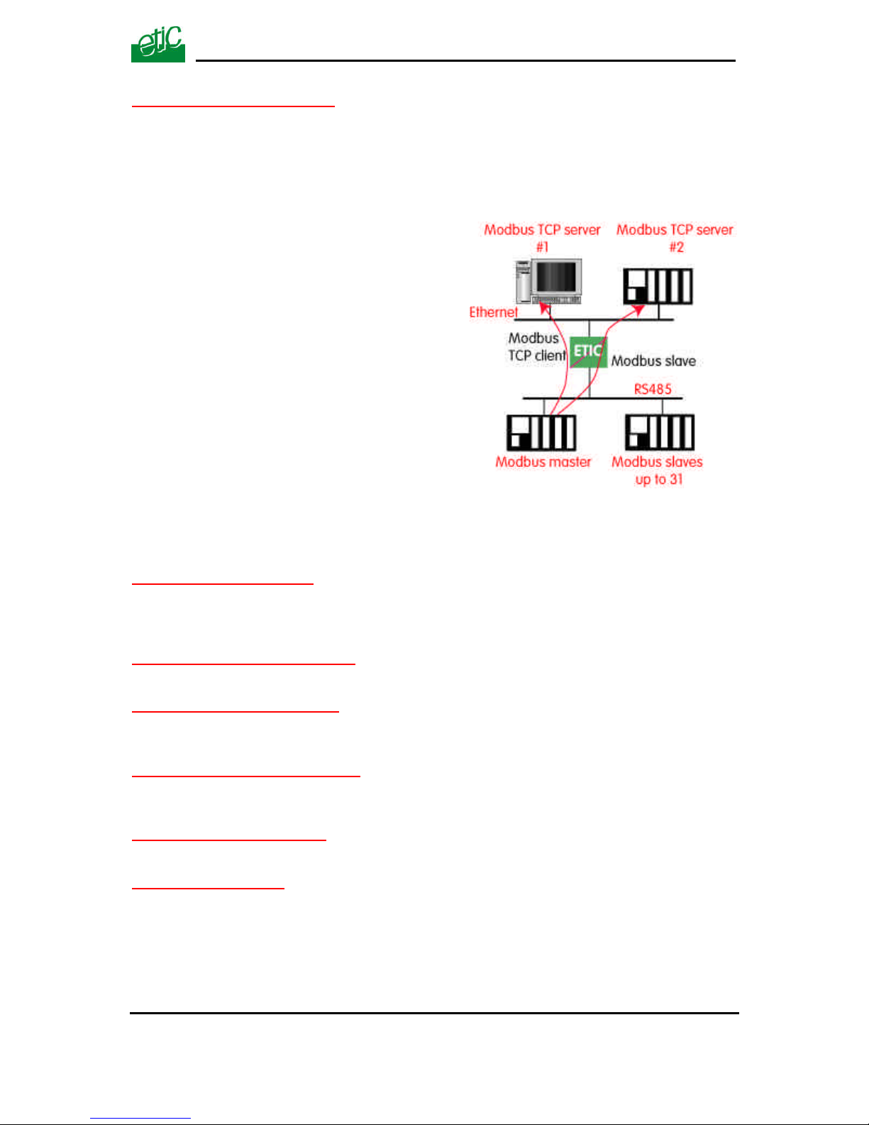
SET UP
UMTS GPRS EDGE router ref. IPL-3G User guide ref. 9019409-01 Page 83
“TCP port number” parameter :
Set the port number the gateway has to use.
If the Raw TCP client gateway is assigned to both serial COM ports, the TCP port numbers must be
different on each port.
21.1.2 Modbus client gateway
This gateway allows to connect a serial modbus
master to the serial interface of the IPRS.
• Select the modbus menu and then “modbus client” menu; enable the “modbus client” gateway and
set up the parameters as follows :
“Port selection” parameter :
Select the serial port COM 1 or COM2.
If the modbus server gateway is assigned to one serial COM port, it cannot be assigned to the other
one.
« ASCII / RTU protocol » parameter :
Select the right option
“Inter-character gap” parameter :
Set up the maximum delay the gateway will have to wait between a received character of a modbus
answer frame and the following character of the same frame.
“TCP inactivity Timeout” parameter :
Set the time the gateway will wait before disconnecting the TCP link if no characters are detected.
“TCP port number” parameter :
Set the TCP port number the gateway has to use.
“IP address” parameter :
The modbus client gateway allows to transmit modbus requests from the serial modbus master device
to any modbus slave device, more precisely called “ modbus server”, located on the IP network.
To assign an IP address to each modbus slave device with which the serial master device needs to
communicate, click the “add a link” button; Assign an IP address in front of each modbus slave
address with which the serial master device will have to communicate.
Page 84
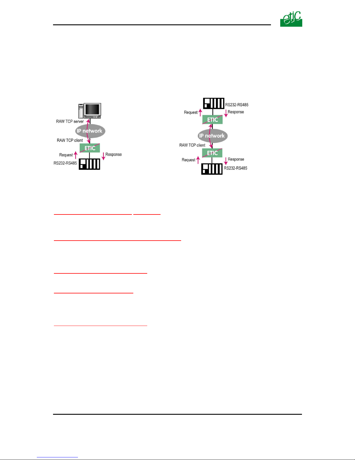
SET UP
Page 84 User guide ref 9019409-01 UMTS GPRS EDGE router ref. IPL-3G
21.2 RAW TCP gateway
21.2.1 Raw client gateway
The RAW client gateway can be used if a serial “master” device has to send requests to one slave
device (also called server) located on the IP network.
The server can be either an ETIC gateway or a PC including a software TCP server.
• Select the “transparent” and then the “raw client COM1” or the “raw client COM2” menu .
• Enable the raw client gateway; and set up the parameters as follows :
“RS232/485 input buffer size” parameter :
Set up the maximum length of an asynchronous string the gateway will store before transmitting it to
the IP network.
“Timeout of RS232/485 end of frame” parameter :
Set up the delay the gateway will wait before declaring complete a string received from the
asynchronous device.
Once declared complete, the gateway will transmit the string to the IP network.
“TCP inactivity Timeout” parameter :
Set the time the gateway will wait before disconnecting the TCP link if no characters are detected.
“TCP port number” parameter :
Set the port number the gateway has to use.
If the Raw TCP client gateway is assigned to both serial COM ports, the TCP port numbers must be
different on each port.
“Raw server IP address” parameter :
The raw client gateway is able to communicate with a raw server gateway.
Assign an IP address to define the destination gateway.
Page 85
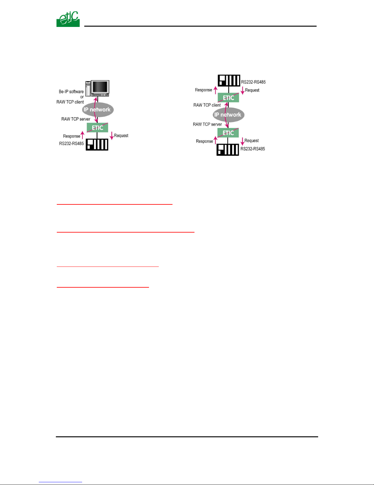
SET UP
UMTS GPRS EDGE router ref. IPL-3G User guide ref. 9019409-01 Page 85
21.2.2 Raw server gateway
That gateway can be used if a serial slave device has to answer requests coming from devices
located on the IP network and acting like a master (also called TCP client).
• Select the “transparent” and then the “raw server COM1” or the “raw server COM2” menu.
• Enable the raw server gateway and set up the parameters as follows :
“RS232/485 input buffer size” parameter :
Set up the maximum length of an asynchronous string the gateway will store before transmitting it to
the IP network.
“Timeout of RS232/485 end of frame” parameter :
Set up the delay the gateway will wait before declaring complete a string received from the
asynchronous device.
Once declared complete, the gateway will transmit the string to the IP network.
“TCP inactivity Timeout” parameter :
Set up the time the gateway will wait before disconnecting the TCP link if no characters are detected.
“TCP port number” parameters :
Set up the port number the gateway has to use.
If the Raw TCP server gateway is assigned to both serial COM ports, the TCP port numbers must be
different on each port.
Page 86
SET UP
Page 86 User guide ref 9019409-01 UMTS GPRS EDGE router ref. IPL-3G
21.3 RAW UDP gateway
21.3.1 Overview
The RAW UDP gateway enables you to connect together a group of serial or IP devices through an
IP network.
The group can include IP devices if they have the software pieces able to receive or transmit serial
data inside UDP.
Serial data transmitted by each device is transmitted to all other serial devices through the IP
network.
A table of IP destination gateways is stored in each IPL-3G belonging to the group.
The serial data is encapsulated in the UDP protocol.
The UDP frame is sent to each destination IP address stored in the table.
21.3.2 Configuration
• Select the “gateway” menu and then the “Transparent” menu and then click “RAW UDP”.
• Select the “Activate” option.
« Serial input buffer size” parameter (value 1 to 1024) :
Sets the maximum size of an UDP frame.
“End of frame time-out” parameter (value 10 ms to 5 sec ) :
Sets the delay the gateway will wait before sending the UDP frame towards the IP network when no
characters are received from the serial interface.
«UDP port number» parameter :
Sets the UDP port number.
If the Raw UDP gateway is assigned to both serial COM ports, the UDP port numbers must be
different on each port.
“IP addresses of the destination devices » table :
This table stores the IP addresses of the gateways to which the serial data, encapsulated inside UDP, have to be
sent.
Page 87

SET UP
UMTS GPRS EDGE router ref. IPL-3G User guide ref. 9019409-01 Page 87
A different UDP port number can be entered for each destination IP address.
Page 88
SET UP
Page 88 User guide ref 9019409-01 UMTS GPRS EDGE router ref. IPL-3G
22 USB to IP gateway
22.1 Principles
The IPL-3G-1201 provides a USB to IP gateway.
It is able to forward IP traffic from devices connected to the Ethernet network to a USB device.
On the USB interface, the IPL-3G-1201 behaves like a USB host and a PPP client.
The USB device connected to the IPL-3G-1201 USB interface must behave like a PPP server.
Destination IP address; main case
When a device, connected to the Ethernet network, needs to transmit data to the USB device, the
destination address of the IP frames which need to be transmitted to the USB device must be a
specific IP address assigned to the USB gateway of the IPL-3G (see the configuration below).
Destination IP address; Modbus case
If no specific IP address is assigned to the USB gateway (see below), the IPL-3G forwards only
modbus TCP traffic to the USB interface.
The destination IP address of the IP frames must be the LAN IP address of the IPL-3G router.
22.2 Configuration
Select the “Setup” menu and then the “USB” menu.
“Activate” checkbox :
Select the “Activate” checkbox.
“Use a specific IP address” checkbox :
If modbus TCP traffic only has to be forwarded to the USB device, that checkbox must not be
selected.
If other kinds of traffic have to be forwarded, that checkbox has to be selected.
“Specific IP address” parameter :
If modbus TCP traffic only has to be forwarded to the USB interface, no IP address has to be entered.
If other kinds of traffic have to be forwarded to the USB device, an additional IP address must be assigned the
IPL-3G.
That address belongs to the network connected to the LAN interface of the IPL-3G. It is the IP address of the
USB gateway.
It will be used as the destination IP address of the IP frames which must be forwarded to the USB device.
“Accept WAN traffic” checkbox:
It is necessary to select that checkbox it the PC is connected to the network connected to the WAN
interface.
It is not necessary to select that checkbox if the remote PC is connected to the RAS through a VPN.
Page 89

SET UP
UMTS GPRS EDGE router ref. IPL-3G User guide ref. 9019409-01 Page 89
23 Advanced functions
23.1 Adding a certificate
Coming from the factory, the IPL-3G router includes a certificate delivered by ETIC
TELECOOMUNICATIONS acting as a certification authority.
That certificate can be used to set a VPN between two routers.
Two IPL-3G routers can set a VPN with one another using certificates only if the certificates have
been provided by the same authority.
Additional X509 certificates, provided by ETIC Telecommunications or not, can be downloaded into
the router.
To import a new certificate, the file extension can be PKCS#12 with a password or PEM.
Even if more than one certificate have been downloaded into the IPL-3G router, one certificate can
be used for all the connections.
23.2 Alarms
23.2.1 SNMP
The IPL-3G router is able to send snmp traps when alarms occur.
Activation :
If that option is selected, the router will send an SNMP trap if an alarm is detected.
SNMP network management IP address :
Enter the IP address of the management platform
SysName & SysLocation :
That fields allow to identify the source device.
Example :
Sysname : etic
Syslocation : France
Product start-up :
If that option is selected, the router will send an SNMP trap each time it will connect to the Internet
23.2.2 Digital output alarm
If an alarm occurs, the router will open the digital output..
The causes which make the output to open cane be either the
ADSL disconnection, power input 1 failure, power input 2 failure.
23.2.3 E-mail alarm
When the digital input is closed or opened, an email can be transmitted to one of the users of the
users list.
To set that function select the “Alarm” menu and click “email”.
Page 90

SET UP
Page 90 User guide ref 9019409-01 UMTS GPRS EDGE router ref. IPL-3G
Enable the alarm email :
Select this option if you want an email to be sent to a user when the digital input 1 is set ON or OFF.
Alarm launched on event :
If the option OPEN is selected, the alarm will be sent each time the digital input will be opened.
If the option CLOSED is selected, the alarm will be sent each time the digital input will be opened.
If the option BOTH is selected, the alarm will be sent each time the digital input will be opened or
closed.
Hold time :
Select the time the input has to stay in its alarm state to be taken into account.
Alarm destination :
Select the user to whom the email must be sent.
Text to send :
Enter the email text.
23.3 Configuring the web portal
The web portal in an html page; it displays a list of devices connected to the LAN. Each line of the list
is made of the device name, its IP address and three links :
The html link : To go directly to the web server of the associated machine.
The « explore » link : To explore the HD of the associated machine, if it is a Windows machine.
The « ftp » link : To explore the files of the associated device.
If the we portal option has been selected (see below), the web portal page is displayed when the
remote user launches the navigator and enters the Ip address assigned to the IPL-3G router. In that
case, the administration server, usually can be displayed at the same address but at the port number
8080 instead of 80 when the web portal page option is not selected.
Page 91

SET UP
UMTS GPRS EDGE router ref. IPL-3G User guide ref. 9019409-01 Page 91
23.4 Configuring the DNS server
For domain names resolution, the IPL-3G can behave like a domain name server or a domain name
relay.
DNS server :
A domain name server is a networking device which is able to associate a label (etictelecom.com for
instance) with an IP address.
That function allows a client device to send a request to a network equipment referring to a domain
name as if it was the actual IP address of the destination device.
The IPL-3G router is able to resolve any domain name composed with the name of one of the devices
entered in the devices list followed the site name which is entered at the top of the devices list.
DNS relay :
The IPL-3G router behaves also like a DNS relay; any DNS request it receives from the LAN, which
cannot be resolved because the device is not registered in the devices list, will be transferred to the
internet to be resolved.
That function can be carried out only if the IPL-3G IP address is pointed out as the main DNS server
of the devices of the LAN.
That function is efficient in particular when a device connected to the LAN has to send emails through
the Internet.
Page 92

Page 93

DIAGNOSTIC & MAINTENANCE
UMTS GPRS EDGE router ref. IPL-3G User guide ref. 9019409-01 Page 93
1 Diagnostic menu
The html server provides extended diagnostic functions.
Select the Diagnostic menu and then the appropriate sub-menu.
• Log sub-menu:
The log displays the last 300 dated events :
3G, VPN and users connections and disconnections,
power on,
Serial gateway events.
• Network status sub-menu and then status sub-menu :
That screen displays the current status of the LAN interfaces and of the WAN (3G) connection :
LAN interfaces :
That part of the page shows the data of the LAN interface :
MAC address,
Ethernet mode (10 /100, half or full),
IP address.
WAN interface (3G-GPRS-EDGE) :
3G signal strength :
It must be better than – 90 dBm to en
Remark : A s the number is negative, -85 dBm is better than –90 dBm for instance.
State : Connected or not to the 3G network
Local IP address :
It is the IP address assigned by the provider to the « antenna » (WA interface) over the 3G
network.
In other words, it is the PPP client IP address.
Remote IP address :
It is the IP address of the PPP server belonging to the 3G network.
• VPN sub-menu
That menu displays the table of the VPN (remote user connections and remote routers connections)
which are established.
Page 94

DIAGNOSTIC & MAINTENANCE
Page 94 User guide ref 9019409-01 UMTS GPRS EDGE router ref. IPL-3G
• Serial gateway :
That page displays the current status of the serial gateways :
Type of the gateway(Modbus, RAW, Telnet …),
serial port set-up (data rate etc…),
number of characters received or sent,
Number of TCP frames or UDP datagrams received or sent,
Number of TCP connections enabled.
The View link displays a window which shows the hexadecimal received and transmitted traffic over
each serial COM port.
It can be a great help for trouble shooting.
.
Page 95

APPENDIX 1
DIAGNOSTIC & MAINTENANCE
UMTS GPRS EDGE router ref. IPL-3G User guide ref. 9019409-01 Page 95
2 Saving the configuration to a file
Once a product has been configured, the parameters file can be stored and restored when
necessary.
To save the parameters into a file,
Select the “System” menu and then “Save restore”,
Click the ”Save” button
Select the location to store the configuration and give a name to the file.
The file suffix is “.bin”.
To restore a parameters file
Select the “System” menu and then “Save restore”,
Click the “browse” button and select the parameters file,
Click the “Load” button and confirm to restart the product.
Attention :
A parameters file can only be downloaded to a product having the same firmware version.
It is why, we advise to assign a name to a parameter file including the product name and the software
version.
Example :
Name of a parameters file for an IPL-AD2-1220 router with the firmware version V2.4 :
Myrouterfile_iplad21220_V241.bin
Page 96

DIAGNOSTIC & MAINTENANCE
Page 96 User guide ref 9019409-01 UMTS GPRS EDGE router ref. IPL-3G
3 Updating the firmware
Step 1 : Before starting, you need,
A PC with a Web browser.
An Ethernet cable or a switch
The FTP server software which can be downloaded from the « firmware page » of the ETIC «
download area » web server.
Step 2 : Download the release of the firmware from our download area to your PC
Step 3 : Prepare the PC
Check the Ip address of the PC is compatible with the one of the router.
Connect the router to the PC.
Launch the TFTP server (tftp32.exe) software and select the new release (L026xxx/img) by using the
"Browser" button.
Click on "Show dir" to check the files of the directory : rfsmini.tgz, rootfs.bin, u-boot.bin and uImage.
Step 4 : Update the firmware
Launch the web browser
Enter the IP address of the ETIC product ; the home page of the ETIC configuration server is
displayed.
Select the "System" menu and then " firmware Update". In the field "IP address of the TFTP server",
enter the IP address of your PC.
Note : The IP address of the PC is written in the field "Server Interface" in the TFTP server windows.
Click "Save" and then "Update".
The first file should begin to be downloaded from the PC to the router.
During the operation, the led blinks
When the download is finished, the product automatically reboots.
Check the new release has been installed, go to "About" in the administration web page of the IP
product.
Page 97

Management web server
UMTS GPRS EDGE router ref. IPL-3G User guide ref. 9019409-01 Page 97
1/ Setup menu
Remote users To assign an ID and PWD to each authorized user and set their rights
To set the M2Me service
LAN interface To enter the IP @ of the router on the LAN interface.
To enter the IP @ assigned to the remote users
To set up the Ethernet interfaces
To set up the DHCP server on the LAN interface
WAN interface To enter the IP @ of the router over the WAN interface.
Network To configures the VPNs
To enter static routes and enable the RIP protocol
To set up the VRRP redundancy protocol
To set up port forwarding
To set up advanced Ip addr. translation functions
Security To set the firewall rules (User filter and main filter)
To add a certificate
To restrict access to the administration server
Alarm To set up alarm SNMP traps
To set up alarm emails
Serial gateway To set up the modbus gateway (client / server)
To set up the Unitelway gateway
To set up the RAW TCP / RAW UDP / TELNET gateways
System To set up SNMP parameters
To enter the devices list
To update the service list
To update time and date
2/ Diagnostic menu
Log To display the events ( VPN connections, user connections..)
Network status Interfaces status : @ MAC, @IP, ADSL, VPN
VPN status
Routing tables
M2Me_Connect status
Serial gateways To display the status of each gateway (COM1 and COM2)
Tools To send Pings from the router
Hardware To display the input status
To control the output
To display the DIP switches status
Environment To display the internal T° and the supply voltage
Advanced To store the internal report to a disk for diagnostic purposes
3/ Maintenance menu
Firmware update To update the firmware
Save / restore To save or restore a configuration file
To restore the factory configuration
Reboot To restart he router
4/ About menu
Page 98

Page 98 User guide ref 9019409-01 UMTS GPRS EDGE router ref. IPL-3G
To display the certificate “product key”
To display the firmware version
Page 99

Page 100

13, Chemin du Vieux Chêne
38240 Meylan - France
Tel : 33 4 76 04 20 00
Fax : 33 4 76 04 20 01
E-mail : [email protected]
Web : www.etictelecom.com
 Loading...