

Page 1

AFO485 : FIBRE OPTIC MODEM
RFO485 : FIBRE OPTIC REPEATER
_________________
USER GUIDE
Doc. ref : 9011509-01
________________
www.hvssystem.com
Siège social :
2 rue René Laennec
51500 Taissy
France
Contact :
Tél : 0326824929
Fax : 0326851908
Distribué par :
Page 2

Page 2 USER MANUAL ref 9011509-01 AFO485 and RFO485
The AFO485 and RF0485 units are manufactured by
ETIC TELECOMMUNICATIONS
13 Chemin du vieux chêne
38240 MEYLAN
FRANCE
In case of any installation difficulties
please contact your retailer,
or call customer services on one of the following numbers:
TEL : 33 4-76-04-20-05
FAX : 33 4-76-04-20-01
Page 3

AFO485 and RFO485 USER MANUAL ref 9011509-01 Page 3
Table of Contents
1
OVERVIEW........................................................................................ 5
2
AFO485 MODEM WITH ASYNCHRONOUS INTERFACE............... 7
2.1. Function ................................................................................ 7
2.2. Description............................................................................ 7
2.3. Micro-switches ..................................................................... 9
2.4. Connectors ......................................................................... 10
2.5. Asynchronous Interfaces .................................................. 11
2.6. Transmission failure output.............................................. 11
2.7. Fibre optic range ................................................................ 12
3
RFO485 REPEATER WITH ASYNCHRONOUS INTERFACE....... 13
Function.......................................................................................... 13
3.1. BUS network ....................................................................... 13
3.2. Failsafe ring ........................................................................ 14
3.3. Description.......................................................................... 16
3.4. Micro-switches ................................................................... 18
3.5. Connectors ......................................................................... 19
3.6. Asynchronous Interfaces .................................................. 20
3.7. Transmission failure output.............................................. 20
3.7.1 Bus network............................................................... 20
3.7.2 Failsafe ring............................................................... 21
3.8.
Fibre optic range ................................................................ 22
3.8.1 Range between repeaters in a bus network.............. 22
3.8.2 Range of repeaters in a failsafe ring ......................... 23
Page 4

Page 4 USER MANUAL ref 9011509-01 AFO485 and RFO485
4
AFO485 MODEM WITH CAN INTERFACE.................................... 24
4.1. Function .............................................................................. 24
4.2. Description.......................................................................... 25
4.3. Microswitches..................................................................... 25
4.4. Connectors ......................................................................... 26
4.5. Interface using CAN network ............................................ 27
4.6. Transmission failure output.............................................. 27
4.7. Range of modems on the CAN network........................... 28
5
INSTALLATION............................................................................... 30
5.1. Dimensions ......................................................................... 30
5.2. Precautions......................................................................... 30
5.3. Power supply ...................................................................... 30
5.4. Fuse ..................................................................................... 31
5.5. Connection of RS485 or RS422 interfaces....................... 31
Appendix 1 : RS232 cable wiring (ref CAB593)
Page 5

AFO485 and RFO485 USER MANUAL ref 9011509-01 Page 5
1 Overview
The family of AFO485 fibre optic modems and RF0485 fibre optic repeaters allow the
transmission of RS232/RS485/RS422 asynchronous data or a CAN bus via multimode or
single mode fibre optics.
Fieldbus network
The units allow the fibre optic transmission of PROFIBUS DP, MODBUS, UNITELWAY,
SYSMACWAY, and the majority of asynchronous protocols, as well as the extension of a
CAN network.
Local Interface
Depending on the model, the unit provides an RS232, RS422 and RS485 local interface or
a CAN interface.
Point to point, bus or failsafe ring
The AFO485 models allow point to point links.
The RFO485 models have a repeater function and allow a multidrop link or a failsafe ring
to be established.
Line modulation
The data over the Fibre optic is encoded to ensure a range of up to 28km for models
which use single mode fibres.
Transmission failure Information
In case of a cut in the fibre optic link the unit provides a « voltage free » transmission
failure output.
Double DC supply
Two power supply inputs are provided in order to back-up one of the power sources in
case of failure or to replace one power source with another without interfering with the
units functioning.
Page 6

Page 6 USER MANUAL ref 9011509-01 AFO485 and RFO485
The table below shows the characteristics of each of the models.
AFO485 modem - • •
-10 -20 -30 -40 -C10 -C20 -C30 -C40
RS232 – RS485 – RS422
• • • •
PROFIBUS DP
• • • •
MODBUS
• • • •
UNITELWAY
• • • •
OTHER ASYNCHRONOUS PROTOCOLS
• • • •
CAN OPEN
• • • •
Multimode fibre optics
• •
• •
Single mode fibre optics
• •
• •
800 nm optical source
•
•
1300 nm optical source
• • •
• • •
Min. guaranteed optical power budget at 25°C (dB)
Taking into account losses due to the connector.
12 12 17 10 12 12 17 10
Transmission failure output
• • • • • • • •
Double DC power supply
• • • • • • • •
RFO485 repeater - • •
-11 -22 -33 -44
RS232 – RS485 – RS422
• • • •
PROFIBUS DP
• • • •
MODBUS
• • • •
UNITELWAY
• • • •
OTHER ASYNCHRONOUS PROTOCOLS
• • • •
Multimode fibre optics
• •
Single mode fibre optics
• •
800 nm optical source
•
1300 nm optical source
• • •
Min. guaranteed optical power budget at 25°C (dB)
Taking into account losses due to the connector.
12 12 17 10
Transmission failure output
• • • •
Double DC power supply
• • • •
Page 7

AFO485 and RFO485 USER MANUAL ref 9011509-01 Page 7
2 AFO485 modem with asynchronous interface
This section describes AFO485-10 , –20 , -30 and –40 models.
2.1. Function
These products allow point to point transmission via multimode or single
mode fibre optics. They have RS232, RS485 and RS422 asynchronous
interfaces.
The unit permits half-duplex transmission.
The following protocols may be used :
PROFIBUS DP / MODBUS / UNITELWAY / SYSMACWAY, and the
majority of other asynchronous protocols.
2.2. Description
F.O. type ST
connectors
microwitches
6 pts screw block
RS485 / RS422 / Transmission failure output
RS232
9-40 VDC supply voltage
(double input)
Page 8

Page 8 USER MANUAL ref 9011509-01 AFO485 and RFO485
Display
Characters transmitted to the fibre optic.
Characters received from the fibre optic.
LINE
Lit when two AFOs communicate correctly, even when no
character is received. Otherwise off.
Power on.
RS232 / RS485 / RS422
F.O.
Treatment
Transmission failure output 9 to 40 VDC
supply voltage
Asynchronous data
820 nm multimode (AF0485-10)
1300 nm multimode (AF0485-20)
1300 nm single mode (AF0485-30 ou -40)
Page 9

AFO485 and RFO485 USER MANUAL ref 9011509-01 Page 9
2.3. Micro-switches
SWITCHES 1 / 2 / 3
switches 1 2 3
Mandatory positioning ON OFF OFF
SWITCH 4 : RS232, RS485 or RS422 FORMAT
switch 4
8 bits + parity 1 start + 1 stop OFF
8 bits without parity or
7 bits + parity
1 start + 1 stop ON
SWITCHES 5 to 8 : RS232, RS485 or RS422data rate
5 6 7 8
Profibus DP 1.5 Mb/s OFF ON OFF OFF
Profibus DP 500 Kb/s OFF ON OFF ON
Profibus DP
187 500 b/s
OFF ON ON OFF
115 200 b/s
ON OFF OFF OFF
Profibus DP 93 750 b/s OFF ON ON ON
57 600 b/s ON OFF OFF ON
38 400 b/s ON OFF ON OFF
19 200 b/s ON OFF ON ON
9 600 b/s ON ON OFF OFF
4 800 b/s ON ON OFF ON
2 400 b/s ON ON ON OFF
1 200 b/s ON ON ON ON
Page 10

Page 10 USER MANUAL ref 9011509-01 AFO485 and RFO485
2.4. Connectors
Connector 1 : 2 point screw block
Main power supply voltage
Pin Signal Function
1
V+ Voltage: 9 to 40 VDC
2
GND Signal ground
Connector 2 : 2 point connector block
Backup power supply voltage
Pin Signal Function
1
V+ Voltage : 9 to 40 VDC
2
GND Signal ground
Connector 3 : RJ45 local interface connector
non-isolated RS232
Pin Circuits Designation
Terminal-Modem
1 CD 109
Carrier
⇐
2 RX 104
Data reception
⇐
3 TX 103
Data transmission
⇒
4 Not connected
5 SG 102 Signal ground
6 DSR 107
Data set ready
⇐
7 Not connected
8 CTS 106
Clear to send
⇐
Note : The CAB593 cable provides an RS232 DB9 female, instead of the RJ45 connector.
It must be ordered separately. The wiring of the CAB593 / RS232 cable is given in
appendix 1.
Connector 4 : 6 point connector block
RS485 and RS422 local interface non isolated and alarm contact
Pin Signal Function
1 and 2
Transmission failure contact, « voltage free »
I max : 100mA / 24 VDC
3
RS422 B’ Emission RS422 polarity B (To the AFO485)
4
RS422 A’ Emission RS422 polarity A (To the AFO485)
5
RS485 B
Reception RS422 polarity B (To the local terminal)
or RS485 polarity B
6
RS485 A
Reception RS422 polarity A (To the local terminal)
or RS485 polarity A
Page 11

AFO485 and RFO485 USER MANUAL ref 9011509-01 Page 11
2.5. Asynchronous Interfaces
At each end, the asynchronous interface used can be different; for
example, the first modem can be linked to the PC using the RS232
interface while the second AFO485 can be connected to a PLC using the
RS485 or RS422 interface.
RS232 Interface
The RS232 interface is available on an RJ45 plug.
The CAB593 cable has a DB9 female connector for the RS232 link.
It must be ordered separately (see appendix 1).
The CD and DSR and CTS signals are closed by the AFO485 as soon as
the modem receives the modulation from the remote AFO485.
No control signal from the RS232 terminal (DTE) is necessary.
RS485 and RS422 interfaces
The unit has a RS422 (4-wire) and RS485 (2-wire) interface on the 6 point
screw block.
These interfaces are not opto-isolated and must be used for short
distances.
The matching resistor of the bus is not included in the product.
The diagrams of these interfaces are given in § 5.5.
2.6. Transmission failure output
The transmission failure output is closed when the modulation of the
remote modem has been detected even if no data is received from the
fibre optics; the line led is lit.
The transmission failure output is opened as soon as the modulation is
no longer received or when the power is off; the line led is extinguished.
Page 12
Page 12 USER MANUAL ref 9011509-01 AFO485 and RFO485
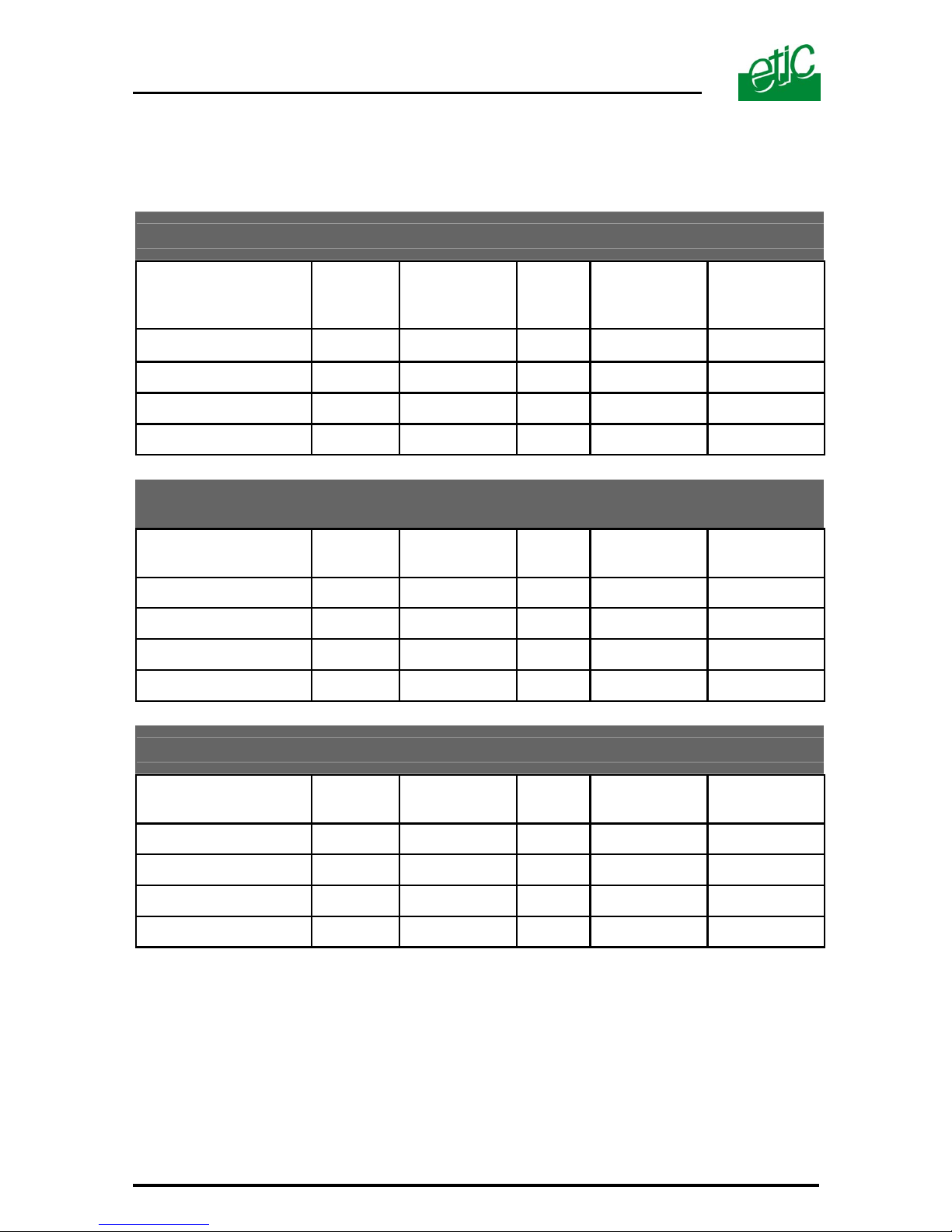
2.7. Fibre optic range
The range depends on the product and the type of fibre used.
Range between 2 modems using multimode fibre G50/125
Optical
Source
Optical
power*
Reserve
F.0.
attenuation
Min. range
dB dB dB/Km Km
Product Reference
A B C D1 = (A-B) / C
AFO485-10
820 nm 12 3 2,5 3,5
AFO485-20
1300 nm 12 3 1 9
Range between 2 modems using multimode fibre G62.5/125
Optical
Source
Optical
power*
Reserve
F.0.
attenuation
Min. range
dB dB dB/Km Km
Product Reference
A B C D1 = (A-B) / C
AFO485-10
820 nm 15 3
3,5
3,5
AFO485-20
1300 nm 15 3
1,5
8
Range between 2 modems using single mode fibre E10/125
Optical
Source
Optical
power*
Reserve
F.0.
attenuation
Min. range
dB dB dB/Km Km
Product Reference
A B C D1 = (A-B) / C
AFO485-30
1300 nm 17 3
0,5
28
AFO485-40
1300 nm 10 3
0,5
14
* Minimum guaranteed power of the optical source at 25°C.
Page 13
AFO485 and RFO485 USER MANUAL ref 9011509-01 Page 13
3 RFO485 repeater with asynchronous interface
This section describes the RFO485-11, –22, -33 and –44 models.
Function
These products allow the repetition of data from one optical link to another
as well as to an asynchronous local interface.
The following protocols can be transmitted :
PROFIBUS DP / MODBUS / UNITELWAY / SYSMACWAY, as well as
most other asynchronous protocols.
The local interface is RS232, RS485 or RS422.
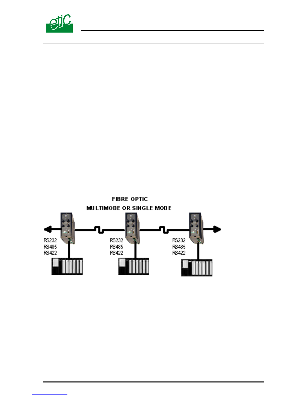
The repeaters allow for the creation of a bus network or a failsafe ring.
3.1. BUS network
Page 14
Page 14 USER MANUAL ref 9011509-01 AFO485 and RFO485
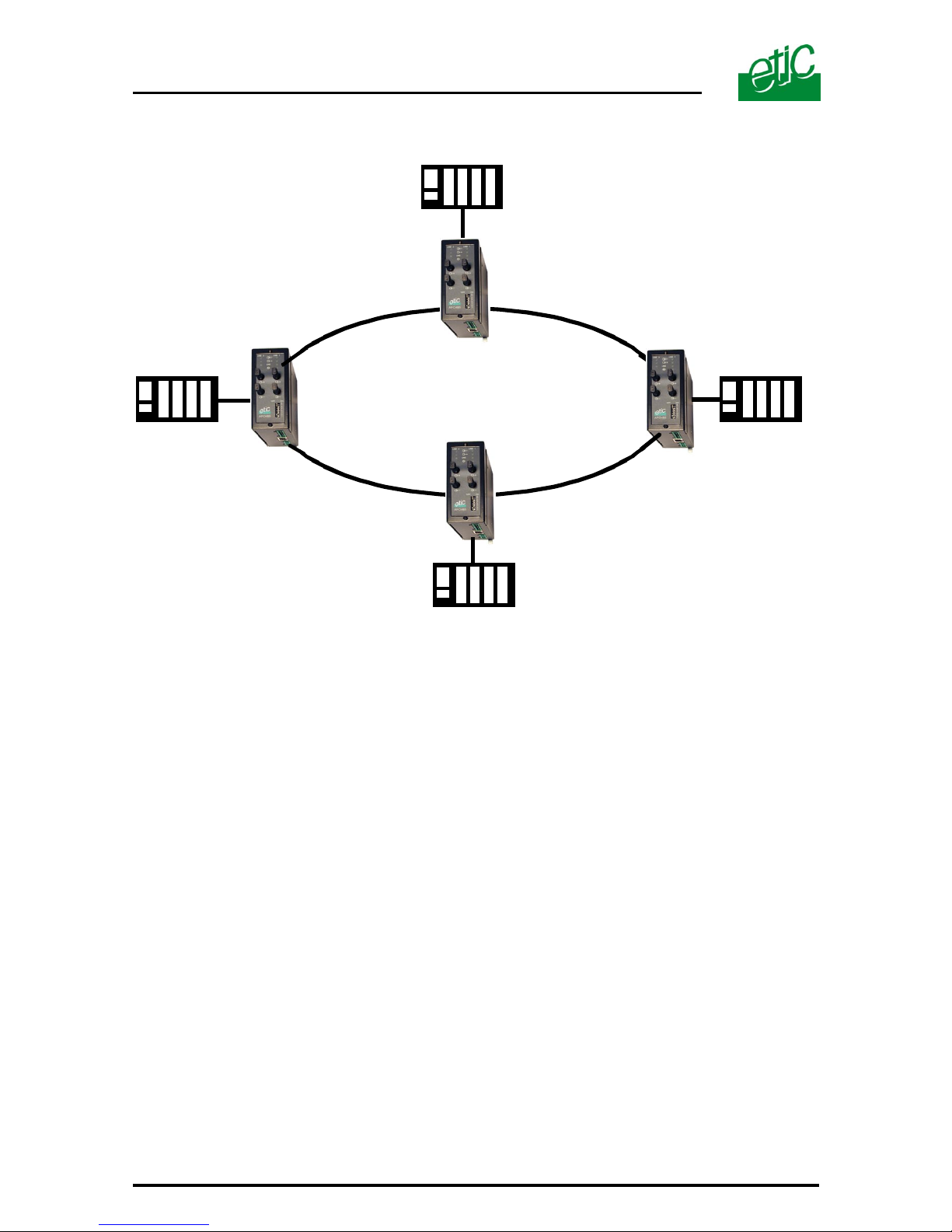
3.2. Failsafe ring
One RFO485 unit must be designated as a « ring master » ;This must be
the unit which is connected to the master PLC of the network.
The role of Master PLC can only be given to one PLC.
Any frame is transmitted over the ring in both of the two possible
directions.
RS232
RS485
RS422
Failsafe ring
RS232
RS485
RS422
RS232
RS485
RS422
RS232
RS485
RS422
Master PLC
ringmaster repeater
Slave repeater
Slave PLC
Slave repeater
Slave repeater
Page 15
AFO485 and RFO485 USER MANUAL ref 9011509-01 Page 15
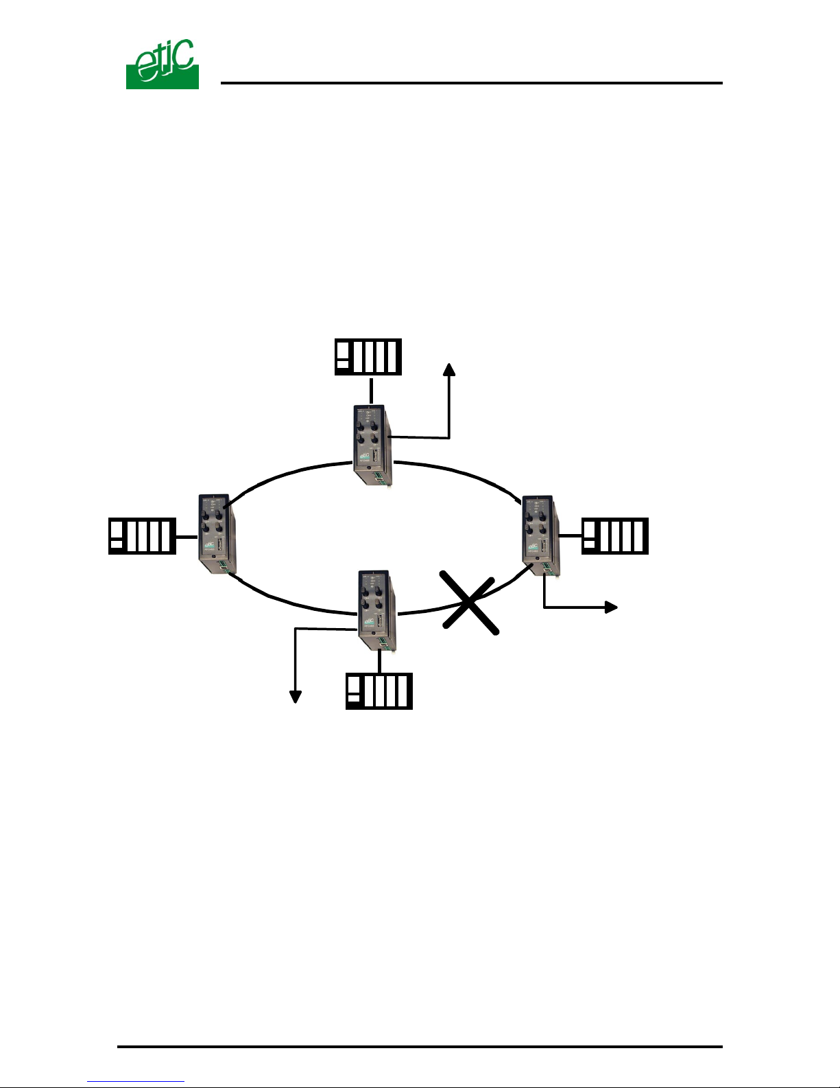
When a segment of the fibre optic cable is faulty, this system allows all
units to nevertheless continue receiving information.
If a failure occurs, the alarm output of the «ring master» RFO485 is
opened as well as the alarm outputs of the RFO485 modules connected to
the segment of fibre optic in failure.
Failsafe ring
RFO485
Ringmaster
Transmission
failure output
Transmission
failure output
Transmission
failure output
Page 16
Page 16 USER MANUAL ref 9011509-01 AFO485 and RFO485
3.3. Description
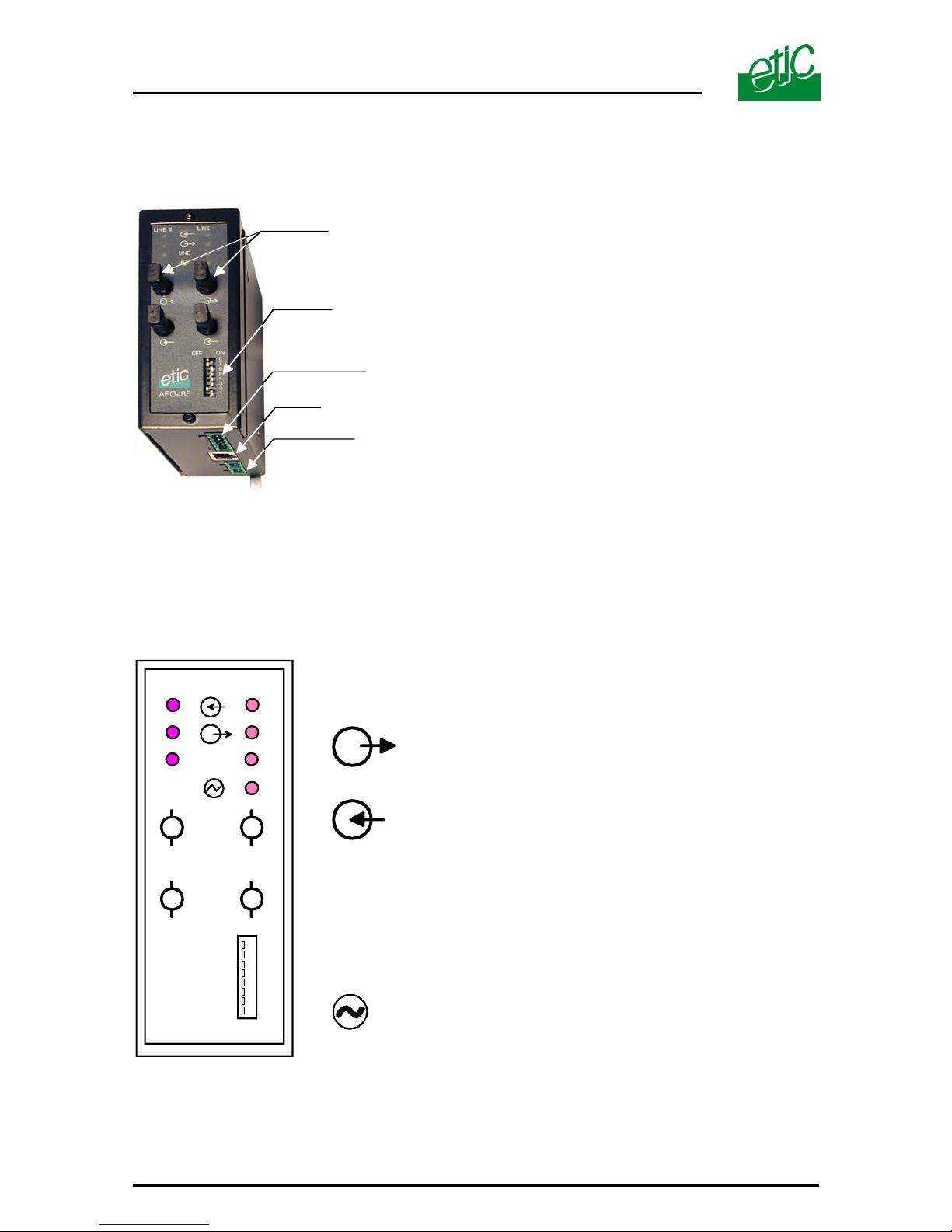
7 leds in total for the 2 optical lines allow for easy monitoring of the units
behaviour:
Leds
Characters sent to the fibre optic.
(LINE 1 or LINE 2)
Characters received from the fibre optic.
(LINE 1 or LINE 2)
LINE
Lit when the optical data link between two RFO485
is established even if no character is sent or
received.
Otherwise off.
Power on.
LINE 2 LINE 1
LINE
Microswitches
RS232
9 to 40 VDC supply V
(double input)
RS485 / RS422 /
Transmission failure output
ST type
F.O. connector
Page 17
AFO485 and RFO485 USER MANUAL ref 9011509-01 Page 17
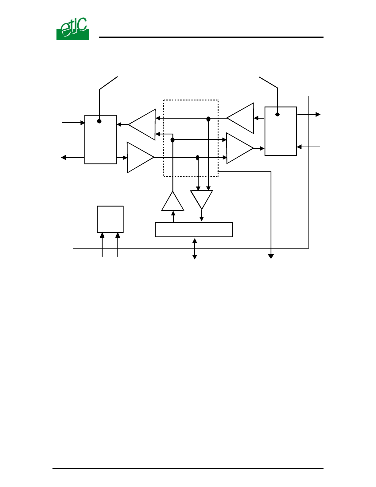
RS232 / RS485 / RS422
F.0.
Line 1
Optical
transmitter
F.0.
Line 2
Double supply V input
9 to 40 VDC
Data
Transmission failure
RFO485
820 nm multimode (RF0485-11)
1300 nm multimode (RF0485-22)
1300 nm single mode (RF0485-33 or -44)
Data treatment
Optical
transmitter
Page 18
Page 18 USER MANUAL ref 9011509-01 AFO485 and RFO485
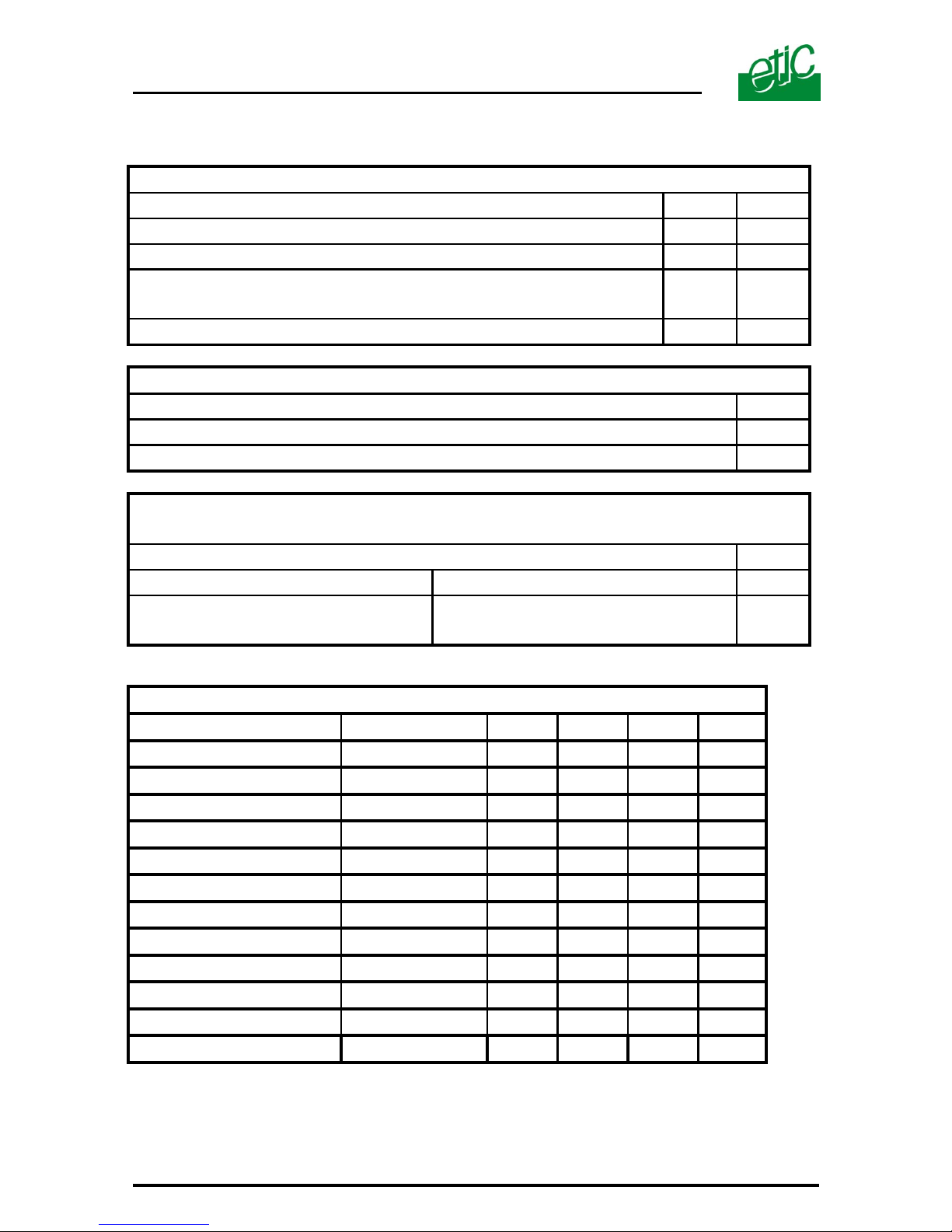
3.4. Micro-switches
SWITCHES 1 and 2 : TYPE OF NETWORK
switches 1 2
Large failsafe ring / master OFF OFF
Small failsafe ring / master OFF ON
Multidrop (= bus repeater)
Failsafe ring / slave
ON OFF
Reserved ON ON
SWITCH 3 : REGENERATION of CHARACTERS
switch 3
The bytes are not regenerated by passing through the repeater OFF
The bytes are regenerated when passing through the repeater ON
SWITCH 4 : FORMAT ON THE ASYNCHRONOUS LINK
RS232, RS485 OR RS422
switch 4
8 bits + parity 1 start + 1 stop OFF
8 bits without parity or
7 bits + parity
1 start + 1 stop ON
SWITCHES 5 to 8 : RS232 RS485 RS422DATA RATE
5 6 7 8
Profibus DP 1.5 Mb/s OFF ON OFF OFF
Profibus DP 500 Kb/s OFF ON OFF ON
Profibus DP 187 500 b/s OFF ON ON OFF
115 200 b/s ON OFF OFF OFF
Profibus DP 93 750 b/s OFF ON ON ON
57 600 b/s ON OFF OFF ON
38 400 b/s ON OFF ON OFF
19 200 b/s ON OFF ON ON
9 600 b/s ON ON OFF OFF
4 800 b/s ON ON OFF ON
2 400 b/s ON ON ON OFF
1 200 b/s ON ON ON ON
Page 19
AFO485 and RFO485 USER MANUAL ref 9011509-01 Page 19
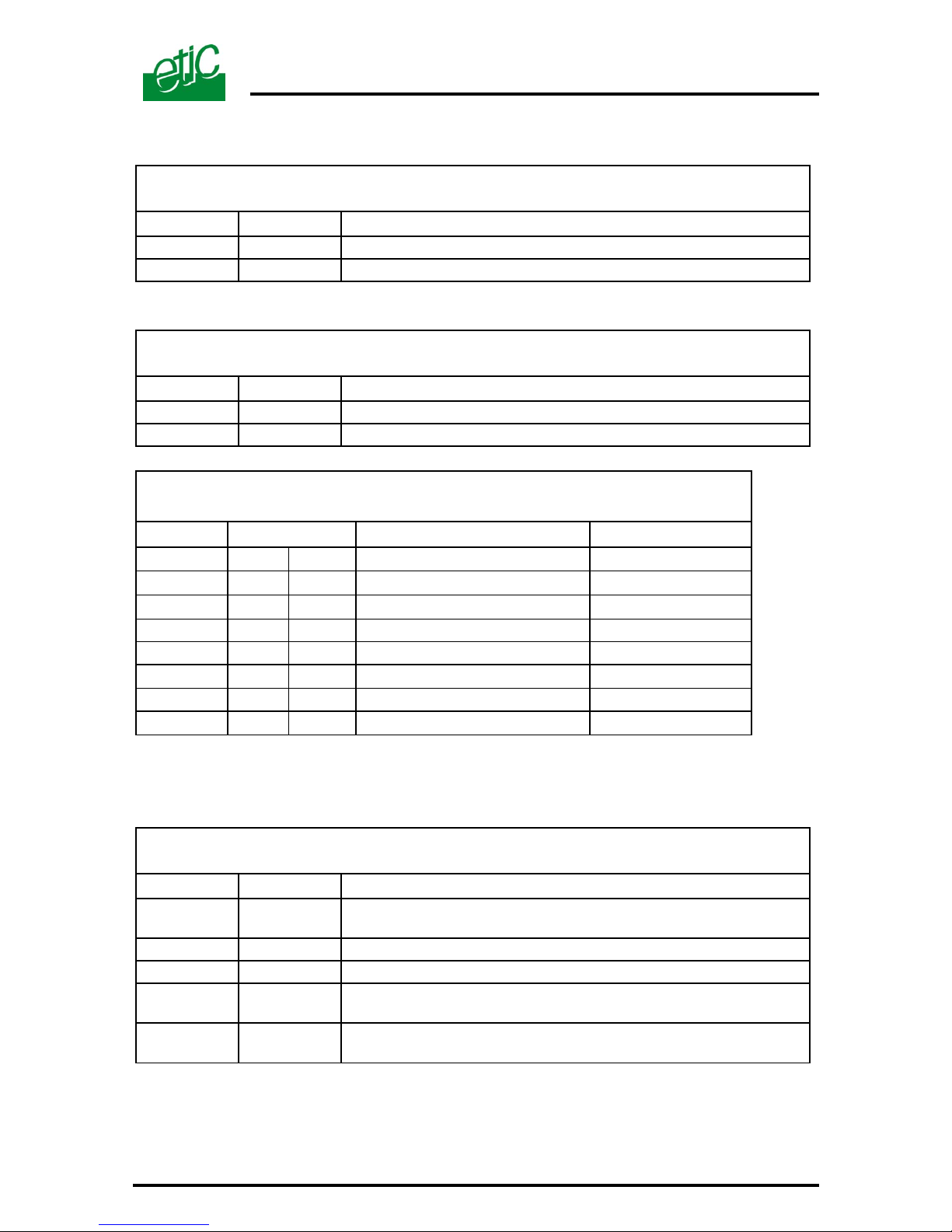
3.5. Connectors
Connector 1 : 2 point screw block
Main power supply
Pin Signal Function
1
V+ Power supply voltage 9 to 40 VDC
2
GND Signal ground
Connector 2 : 2 point connection block
Backup power supply
Pin Signal Function
1
V+ Power supply voltage 9 to 40 VDC
2
GND Signal ground
Connector 3 : RJ45 local interface connector
non-isolated RS232
Pin Circuits Designation
Terminal-Modem
1 CD 109
Carrier
⇐
2 RX 104
Data reception
⇐
3 TX 103
Data transmission
⇒
4 Not connected
5 SG 102 Signal ground
6 DSR 107
Data set ready
⇐
7 Not connected
8 CTS 106
Clear to send
⇐
Note : The CAB593 cable provides an RS232 DB9 female, instead of the RJ45 connector. It must be
ordered separately. The wiring of the CAB593 / RS232 cable is given in appendix 1.
Connector 4 : 6 point connector block
RS485 and RS422 non isolated and Transmission failure output
Pin Signal Function
1 and 2
Transmission failure output / voltage free
I max :
3
RS422 B’ Emission ; RS422 polarity B (to the RFO485)
4
RS422 A’ Emission ; RS422 polarity A (to the RFO485)
5
RS485 B
Reception ; RS422 polarity B (to the local terminal)
or RS485 polarity B
6
RS485 A
Reception ; RS422 polarity A (to the local terminal)
or RS485 polarity A
Page 20

Page 20 USER MANUAL ref 9011509-01 AFO485 and RFO485
3.6. Asynchronous Interfaces
On each RFO485, the asynchronous interface used can be different; for
example, the first modem can be connected to the PC using the RS232
interface while the second AFO485 can be connected to a PLC using the
RS485 or RS422 interface.
RS232 Interface
The RS232 interface is available on an RJ45 plug.
The CAB593 cable has a DB9 female connector for the RS232 link.
It must be ordered separately (see appendix 1).
The CD and DSR and CTS signals are closed by the RFO485 as soon as
it receives the modulation from both remote RFO485.
No control signal from the RS232 terminal (DTE) is necessary.
RS485 and RS422 interfaces
The unit has an RS422 interface (4 wires) and RS485 (2 wires) on the 6
point connector block.
These interfaces are not opto-isolated and must be used for short
distances.
The matching resistor of the bus is not included in the product.
The diagram of these interfaces is given in § 5.5.
3.7. Transmission failure output
3.7.1 Bus network
The transmission failure output is closed when a repeater detects the
modulation on the two optical links to which it is connected, even if no data
is received on either of the two lines.
The leds “lines 1 and 2” are lit.
The transmission failure contact is opened as soon as the modulation
is lost on one of the two optical links to which the repeater is connected or
if the repeater is powered off.
The corresponding led ( line 1 or 2) is extinguished.
Page 21

AFO485 and RFO485 USER MANUAL ref 9011509-01 Page 21
3.7.2 Failsafe ring
- « Ringmaster » repeater
The Transmission failure output is closed
when a repeater detects the modulation on the two optical lines to
which it is connected, even if no data is received on either of the two
lines.
and
When data are received from both sides.
line 1 and line 2 are lit.
The Transmission failure output opens
when the modulation is lost on one of the 2 optic lines to which the
repeater is connected
or
When data are no longer received from both sides.
or
if the unit is powered off.
The corresponding led (line 1 or 2) is extinguished.
- Other repeaters in the ring
The Transmission failure output is closed when a repeater detects the
modulation on the two optical lines to which it is connected, even if no data
is received on either of the two lines.
The leds line 1 and 2 are lit.
The Transmission failure contact closes as soon as the modulation is
lost on one of the two lines to which the repeater is connected or if the unit
is powered off.
The corresponding led ( line 1 or 2) is extinguished.
Page 22
Page 22 USER MANUAL ref 9011509-01 AFO485 and RFO485
3.8. Fibre optic range
3.8.1 Range between repeaters in a bus network
The maximum distance between repeaters is dependant on the product
and the type of fibre optic used; It is the same as that of a point to point
link using the same fibre optic.
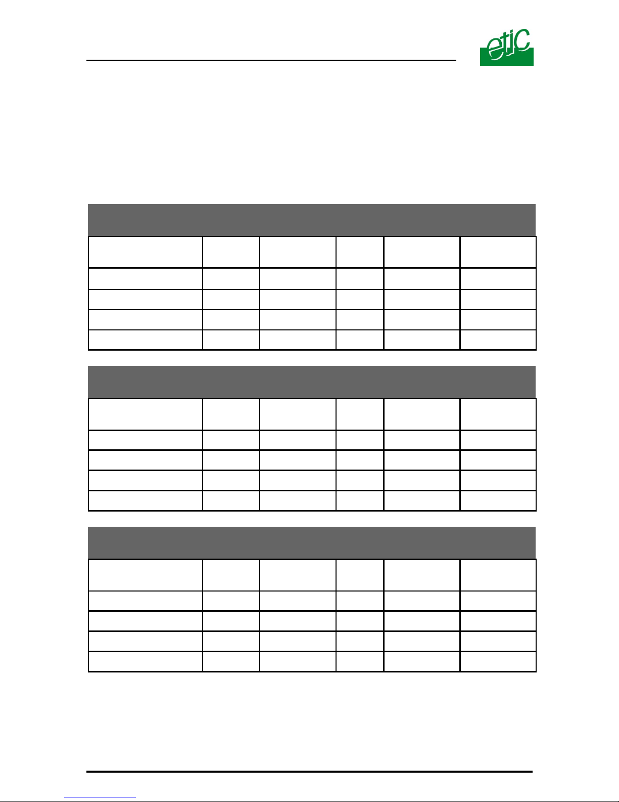
Range between 2 repeaters using multimode fibre G50/125
Bus Network
Optical
Source
Optical
power*
Reserve
F.0.
attenuation
Min. range
dB dB dB/Km Km
Product Reference
A B C D1 = (A-B) / C
AFO485-10
820 nm 12 3 2,5 3,5
AFO485-20
1300 nm 12 3 1 9
Range between 2 repeaters using multimode fibre G62.5/125
Bus network
Optical
Source
Optical
power*
Reserve
F.0.
attenuation
Min. range
dB dB dB/Km Km
Product Reference
A B C D1 = (A-B) / C
AFO485-10
820 nm 15 3
3,5
3,5
AFO485-20
1300 nm 15 3
1,5
8
Range between 2 repeaters using single mode fibre E10/125
Bus Network
Optical
source
Optical
power*
Reserve
F.0.
attenuation
Min. range
dB dB dB/Km Km
Product Reference
A B C D1 = (A-B) / C
AFO485-30
1300 nm 17 3
0,5
28
AFO485-40
1300 nm 10 3
0,5
14
* Minimum guaranteed power of the optical source at 25°C.
Page 23
AFO485 and RFO485 USER MANUAL ref 9011509-01 Page 23
3.8.2 Range of repeaters in a failsafe ring
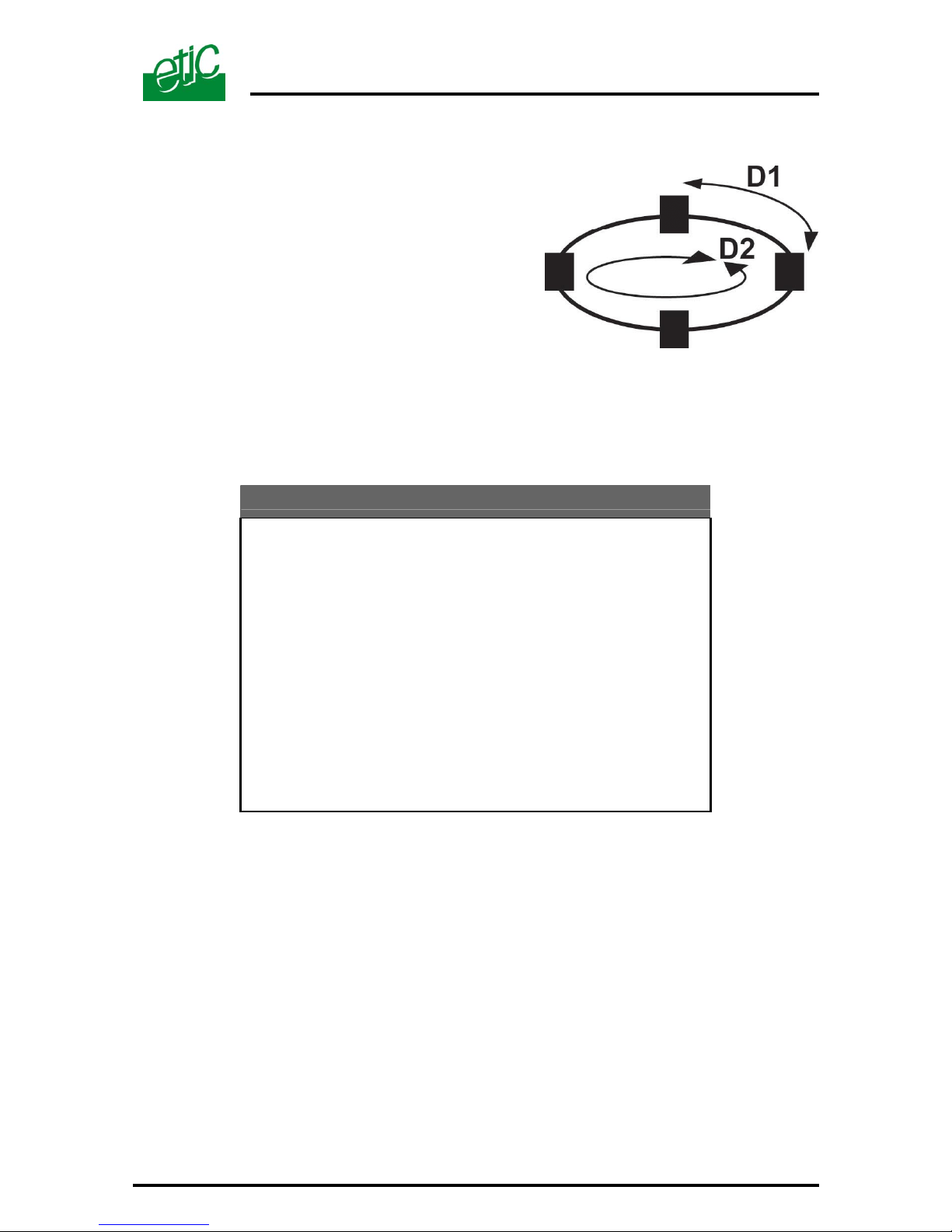
Taking into account the algorithm of the
failure detection used, the maximum size
of the ring is determined in three stages :
Step 1 :The distance D1 between 2
repeaters can not exceed the distances
marked in the tables in section 3.7.1,
these distances depend on the type of
RFO485 and the fibre optic cable used.
Step 2 : Moreover, the distance D1 between 2 repeaters can not exceed
the values in the table below.
Maximum length of a segment of the ring
Kb/s D1 in Km
9,6 20,0
19,2 10,0
38,4 5,0
93,75 2,1
57,6 3,5
115,2 1,7
187,5 1,0
500 0,4
1500 0,1
Step 3 : In addition, the total length of the ring can not exceed the value
D2 given by the formulas below.
If the latency time of the ring is greater than two character lengths:
D2 = 200 X (20-N) / R
If the latency time of the ring is greater than one character length :
D2 = 200 X (10-N) / R
N= Number of repeaters
R (Kb/s) = data rate of the asynchronous link (between 1,2 and 1500)
Page 24
Page 24 USER MANUAL ref 9011509-01 AFO485 and RFO485
4 AFO485 modem with CAN interface
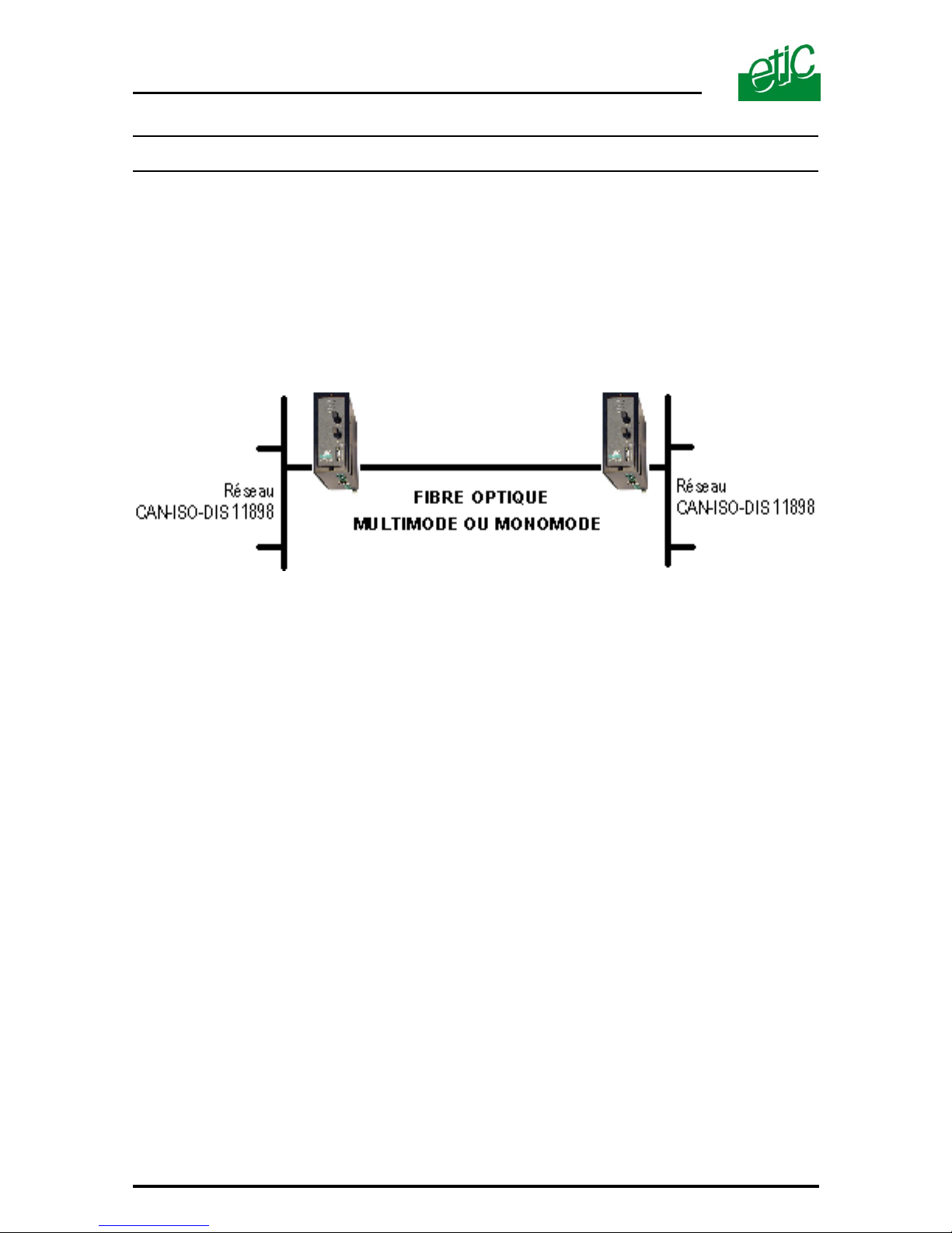
This section relates to products with the reference AFO485-C10, - C20,
- C30 or –C40.
4.1. Function
These products establish an optical link between two segments of a CAN
network.
Page 25
AFO485 and RFO485 USER MANUAL ref 9011509-01 Page 25
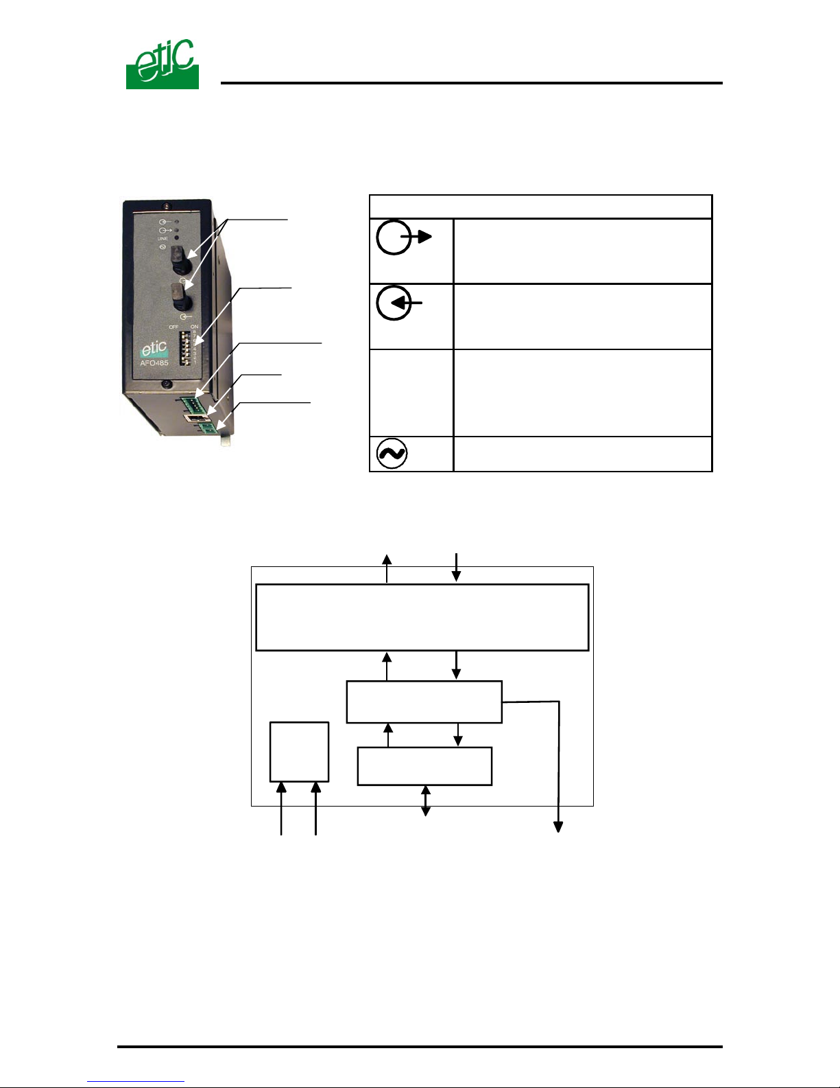
4.2. Description
4.3. Microswitches
The microswitches are ignored, their positioning is unimportant.
Display
Characters transmitted to the fibre
optic.
Characters received from the fibre
optic.
LINE
Lit when two AFO485s communicate
correctly, even when no character is
received. Otherwise off.
Power on.
CAN bus
RS232 (not used)
ST type
F.O. connector
Microswitches
(not used)
9 to 40 VDC supply V
(double input)
CAN-ISO-DIS 11898
Interface
F.O.
Treatment
CAN-ISO-DIS 11898
820 nm multimode (AF0485-C10)
1300 nm multimode (AF0485-C20)
1300 nm single mode (AF0485-C30 ou -C40)
9 to 40 VDC
supply voltage
Transm ission failure output
Page 26
Page 26 USER MANUAL ref 9011509-01 AFO485 and RFO485
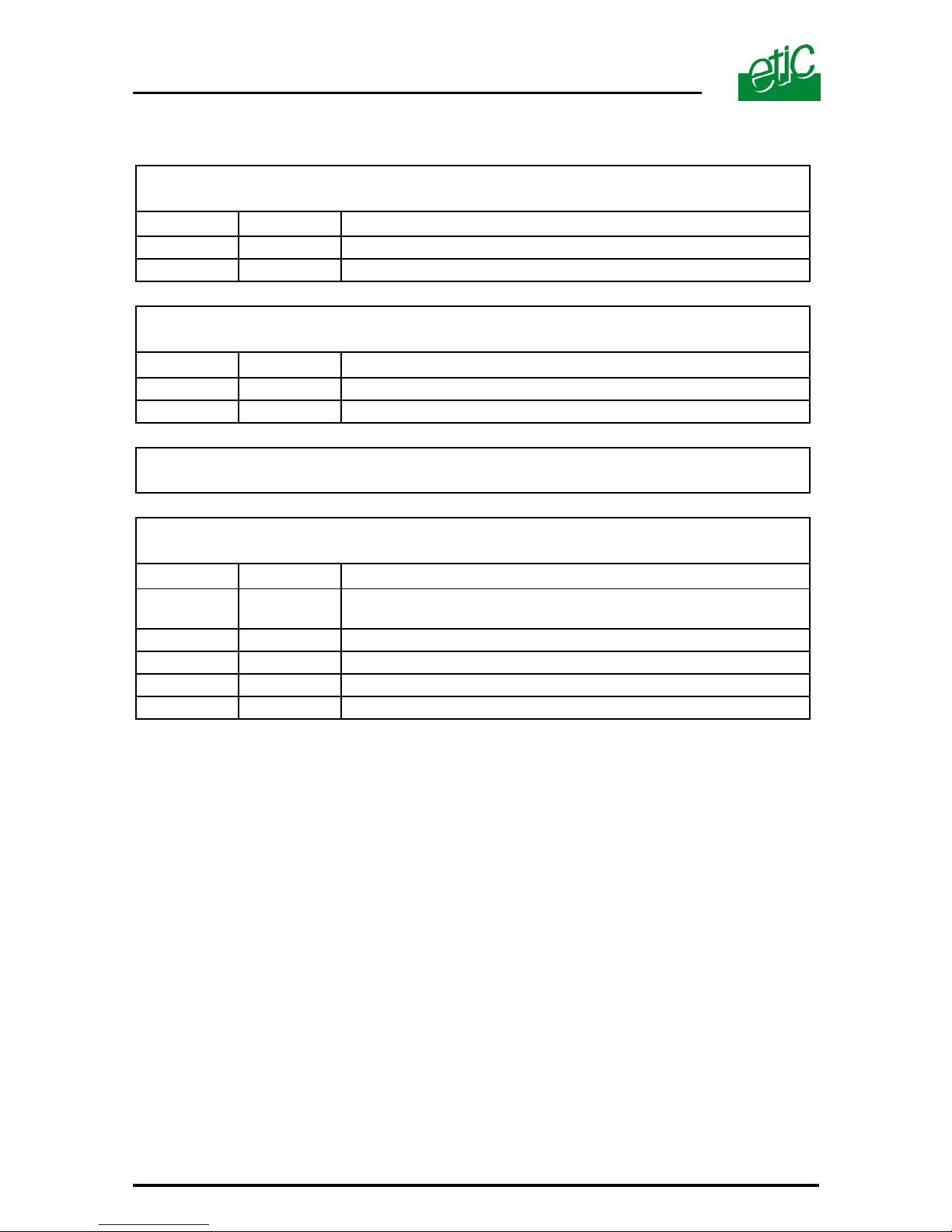
4.4. Connectors
Connector 1 : 2 point connector block
Main power supply
Pin Signal Function
1
V+ Power supply voltage 9 to 40 VDC
2
GND Signal ground
Connector 2 : 2 point connector block
Back-up power supply
Pin Signal Function
1
V+ Power supply voltage 9 to 40 VDC
2
GND Signal ground
Connector 3 : DO NOT USE RJ45
Connector 4 : 6 point connector block
Local CAN interface non isolated and Transmission failure output
Pin Signal Function
1 and 2
Transmission failure contact, « voltage free »
I max :
3
Do not use
4
Do not use
5
L CAN network
6
H CAN network
Page 27
AFO485 and RFO485 USER MANUAL ref 9011509-01 Page 27
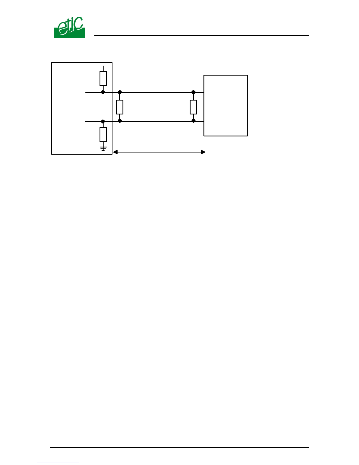
4.5. Interface using CAN network
4.6. Transmission failure output
The transmission failure output is closed when a modem detects the
modulation of the remote modem even if no data is received from the fibre
optics.
The line led is lit.
The transmission failure output is opened as soon as the modulation is
no longer received or when the unit is powered off.
+5v
PLC
AFO485-C10
AFO485-C20
AFO485-C30
4.7 KOhm
4.7 KOhm
(L) Conn.4 / br. 5
(H) Conn.4 / br. 6
120 Ohm120 Ohm
DISTANCE < 3 M
Page 28
Page 28 USER MANUAL ref 9011509-01 AFO485 and RFO485
4.7. Range of modems on the CAN network
Taking into account the technology of the CAN network, only a point to
point transmission can be realised.
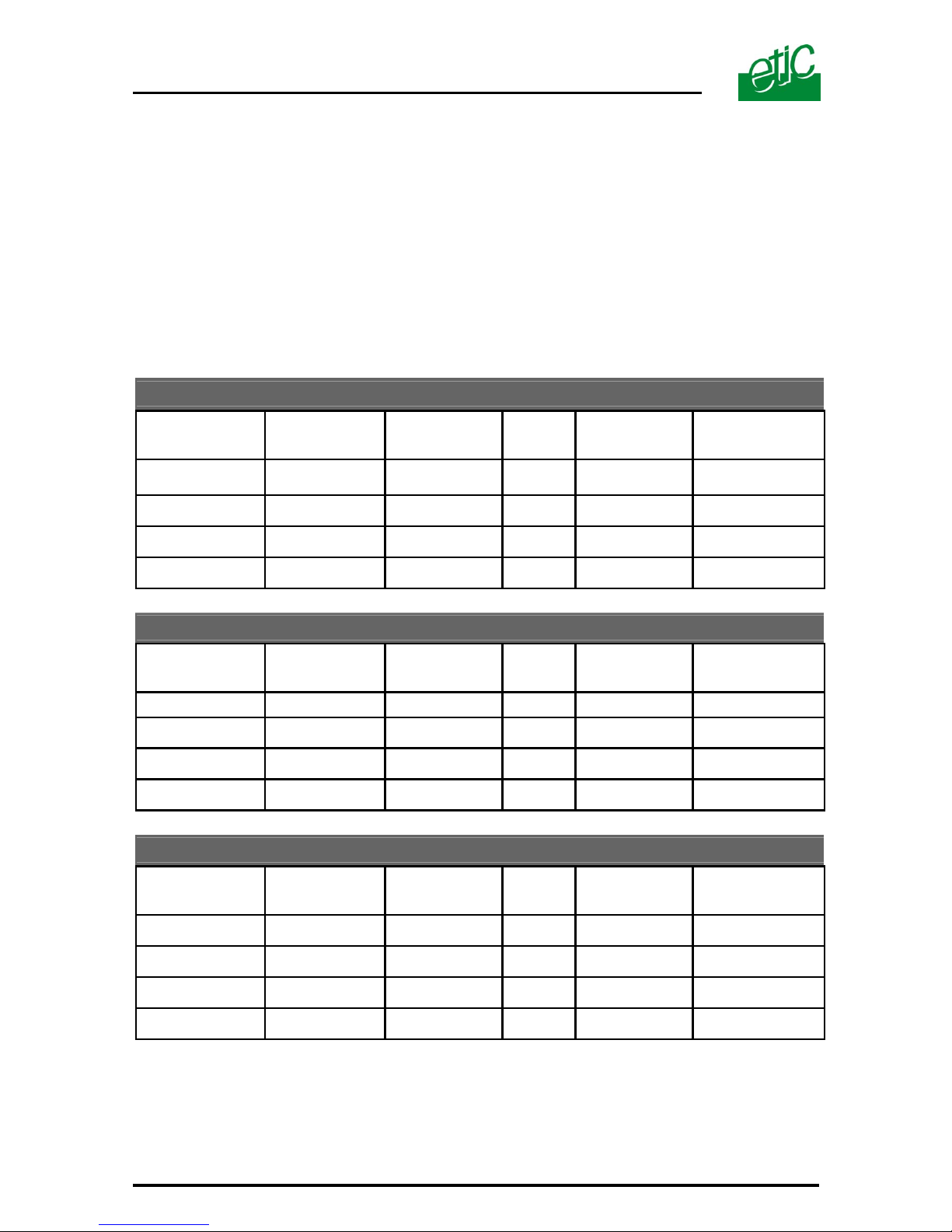
The range of the optical link is determined in two steps :
Step 1 : The length of the link can not exceed the values below, it is
related to the type of fibre optic and the optical source of the AFO485
adaptor.
Range on multimode fibre G50/125
Optical
Source
Optical
power*
Reserve
F.0.
attenuation
Min. range
DB dB dB/Km Km
Product reference
A B C D1 = (A-B) / C
AFO485-C10
820 nm 12 3 2,5 3,5
AFO485-C20
1300 nm 12 3 1 9
Range on multimode fibre G62.5/125
Optical
Source
Optical
power*
Reserve
F.0.
attenuation
Min. range
dB dB dB/Km Km
Product reference
A B C D1 = (A-B) / C
AFO485-C10
820 nm 15 3
3,5
3,5
AFO485-C20
1300 nm 15 3
1,5
8
Range on single mode fibre E10/125
Optical
Source
Optical
power*
Reserve
F.0.
attenuation
Min. range
dB dB dB/Km Km
Product reference
A B C D1 = (A-B) / C
AFO485-C30
1300 nm 17 3
0,5
28
AFO485-C40
1300 nm 10 3
0,5
14
*Minimum power of the optical source at 25°C.
Page 29
AFO485 and RFO485 USER MANUAL ref 9011509-01 Page 29
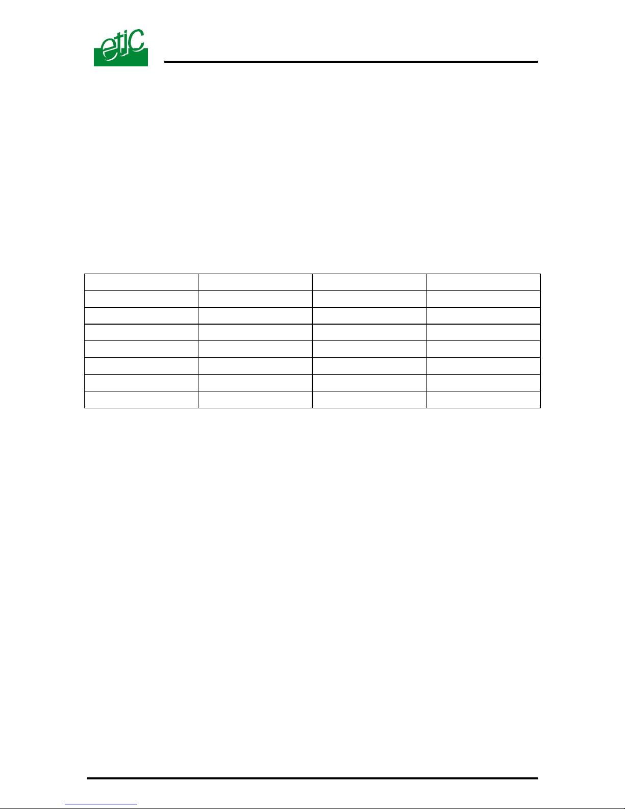
Step 2 : Moreover, independent of the quality of the fibre optic, the
range must not exceed the values in the tables below in relation to:
• the data rate of the CAN network
• the timing of “CAN” bit sampling by the PLC.
The 3
rd
column of the table, titled CIA 87%, corresponds to the
recommended “CAN IN AUTOMATION” normally applied by CAN
interfaces belonging to PLC’s.
The values indicated in this column are the ranges which are
obtained by a PLC using the CIA standard.
1 /2 Tb 2/3 Tb CIA (87%)
10 kb/s
5,9 Km 6,5 km 8,6 km
20 kb/s
2,4 km 3,2 km 4,3 km
50 kb/s
0,9 km 1,2 km 1,6 km
100 kb/s
0,4 km 0,55 km 0,8 km
125 kb/s
0,3 km 0,42 km 0,6 km
250 kb/s
0,1 km 0,16 km 0,23 km
500 kb/s
0 60 m 150 m
Page 30
Page 30 USER MANUAL ref 9011509-01 AFO485 and RFO485
5 Installation
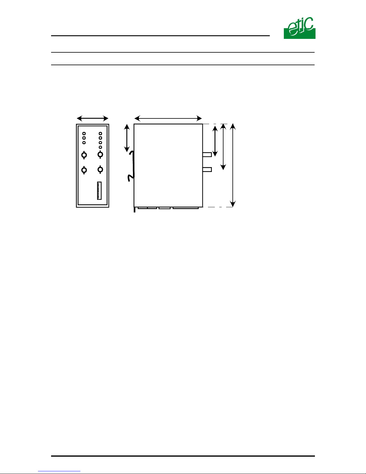
5.1. Dimensions
Dimensions are in mm.
5.2. Precautions
The product was designed to be mounted on a 35mm DIN rail.
To avoid overheating, in particular when the temperature in the cabinet is
liable to rise, a space of 1cm on either side of the unit should be left to
allow the heat to escape.
Sufficient space should also be left in front of the unit in order to account
for the minimum radius of curvature prescribed by the manufacturer of the
fibre optic cable.
You should avoid using excessive force while connecting the fibre optic
cables to avert damage to the optical connectors.
5.3. Power supply
The power supply voltage must be strictly regulated and be between 9 and
40 Volts maximum.
Two DC power supply inputs are available ; if the primary power source
fails the second can continue to provide power to the unit.
The consumption of the AFO485 is 170 mA / 24 VDC.
The consumption of the RFO485 is 250 mA / 24 VDC
115
45
95
42
45
64
LINE 1LINE 2
Page 31
AFO485 and RFO485 USER MANUAL ref 9011509-01 Page 31
5.4. Fuse
The circuit board is equipped with an automatically rearming fuse.
5.5. Connection of RS485 or RS422 interfaces
This section concerns only the models equipped with a RS485 and RS422
interface : AFO485-10, –20, –30 or –40 and RFO485-11, –22, –33 or –44
.
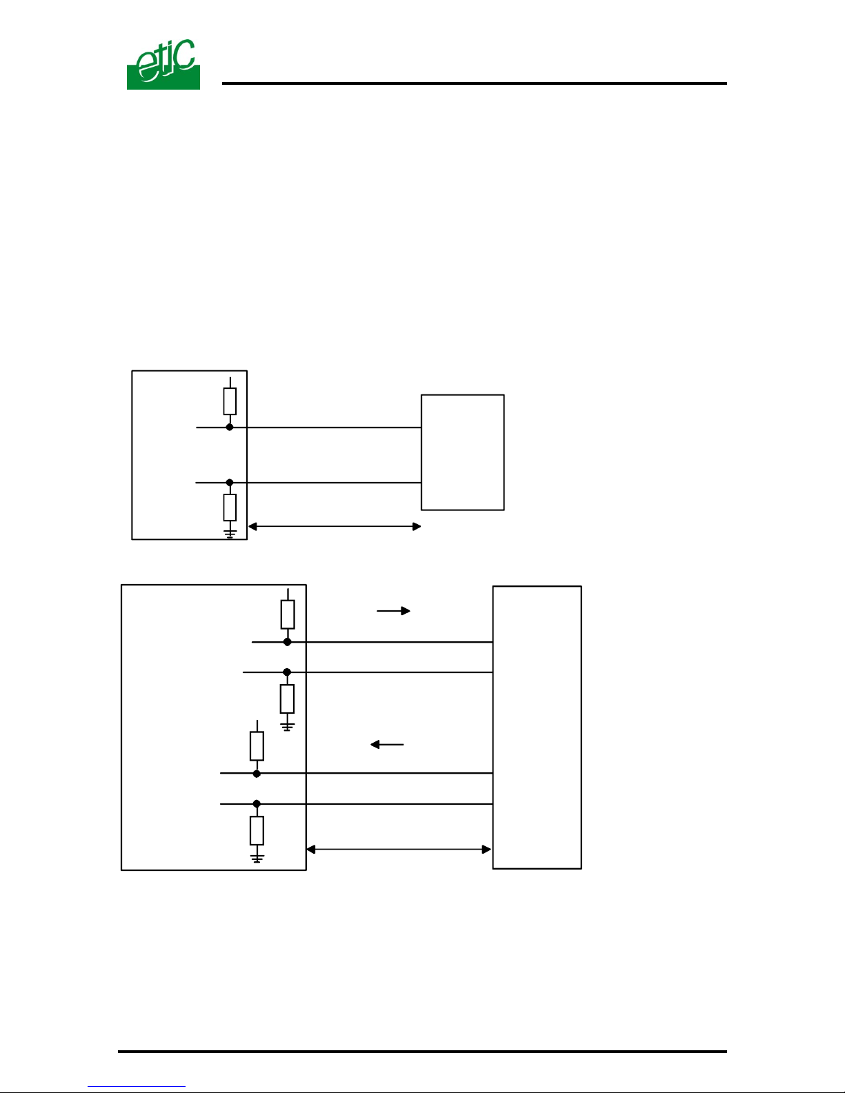
The A and B signals of the RS485 / RS422 interfaces are polarised by the
2.2 Kohm resistors on the circuit board.
When the data rate is high or the length of the RS485 / RS422 bus justifies it, a 120
Ohm matching resistor should be attached to both ends of the network.
(B) Conn.4 / pin 5
2.2 KOhm
+5v
RS485
TERMINAL
PC, PLC...)
2.2 KOhm
(A) Conn.4 / pin 6
Distance < 5 m
AFO485 - RFO485
2.2 KOhm
+5v
RS422
2.2 KOhm
(A) Conn.4 / pin 6
Distance < 5 m
2.2 KOhm
+5v
2.2 KOhm
TERMINAL
(PC, PLC...)
(B) Conn.4 / pin 5
(B') Conn.4 / pin 3
(A') Conn.4 / pin 4
RS422
AFO485
RFO485
Page 32
Page 32 USER MANUAL ref 9011509-01 AFO485 and RFO485
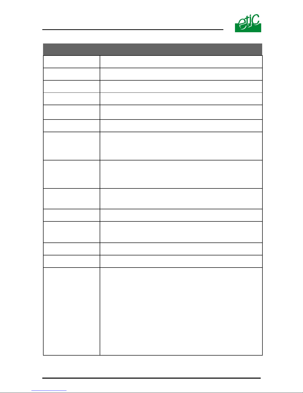
CHARACTERISTICS
Dimensions
115 x 48 x 97 mm (h, l, d)
E.M.I.
EN50082-2 / EN61000-4-5
Electrical security
EN 60950
Protection
IP30
Power supply /
consumption
Double DC power supply 9 to 40 VDC
AFO485 : 170 mA /24 VDC – RFO485 : 250 mA / 24 VDC
Operating temp.
0°C/ + 60°C dry air
RS232
Non isolated
Asynch. 7 or 8 bits + 1 start, 1 or 2 stops
Parity : none / even / odd
1,2 to 115,2 kb/s
RS485 / RS422
Non isolated – Integrated polarisation
Asynch. 7 or 8 bits + 1 start, 1 or 2 stops
Parity : none / even / odd 1,2 to 115,2 - 93,5 - 187,5 - 500 1500 kb/s
Fieldbus
PROFIBUS DP, MODBUS, UNITELWAY, DH-485,
SYSMAC-WAY,
CAN OPEN ISO-DIS-11898
Configuration
By switch
Type of fibre optic
Multimode G50/125 or G62,5/125
Single mode E10/125
Reception fibre and Emission fibre
Optical connector
ST
Modulation
Online data coding
Alarm
Voltage free alarm contact:
Point to point : Open when the unit is no longer receiving
power or if there is a reception failure.
Bus topology: Open when a carrier failure has been
detected on any TX or RX F.O. connected to the repeater.
Ring topology /« ring master» repeater: Open when a
carrier failure has been detected on any F.O. of the ring.
Ring topology / any repeater: Open when a carrier failure
has been detected on any TX or RX F.O. connected to the
repeater.
Page 33
AFO485 and RFO485 USER MANUAL ref 9011509-01 Page 33
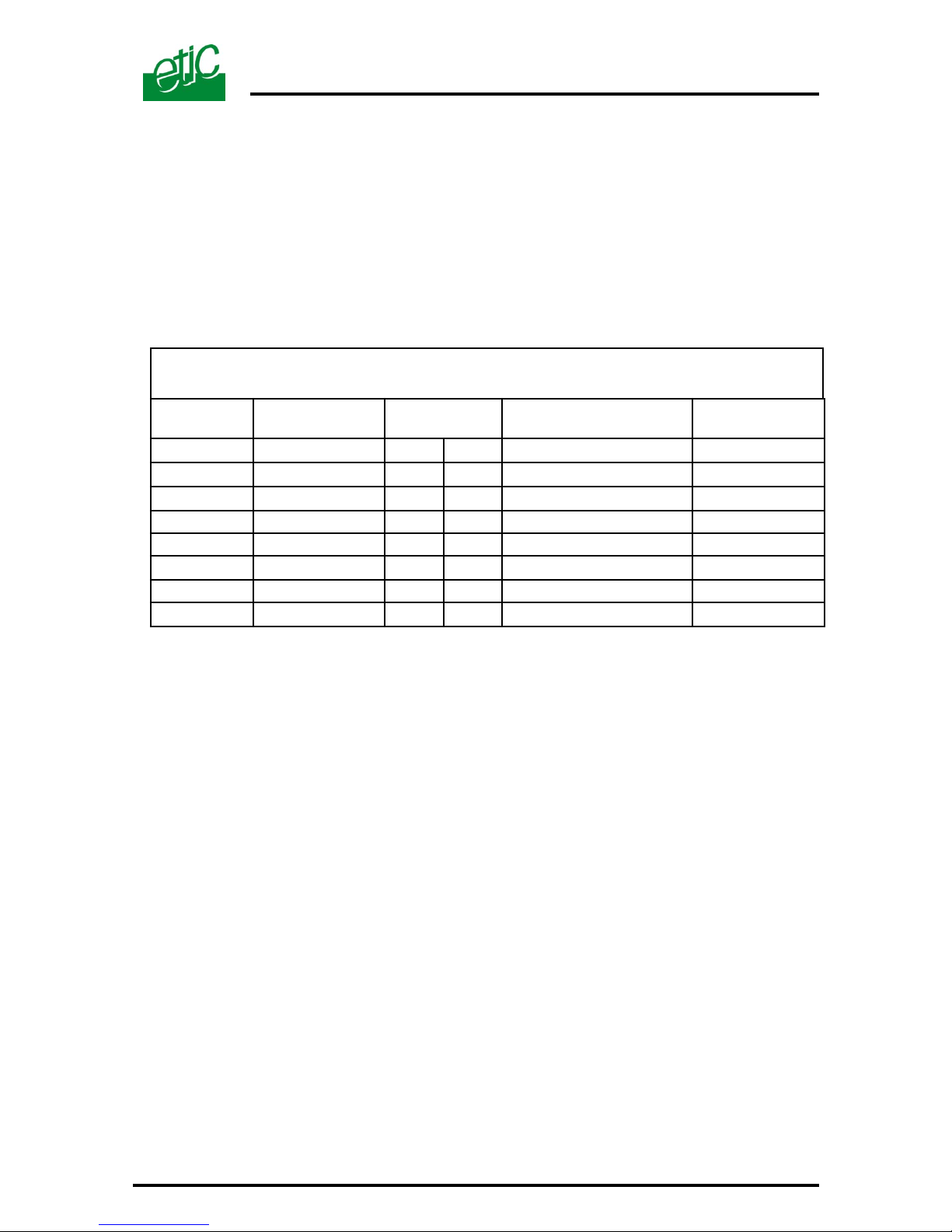
Appendix 1
RJ45 to DB9 female RS232 cable wiring
(ref : CAB593)
RJ45
pin-out
DB9 fem.
pin-out
Circuits Designation Terminal-Modem
1
1
CD 109
Carrier detect
⇐
2
2
RX 104
Data reception
⇐
3
3
TX 103
Data transmission
⇒
4 Not connected
5 5 SG 102 Signal ground
6
6
DSR 107
Data set ready
⇐
7 Not connected
8
8
CTS 106
Clear to send
⇐
Page 34

Page 34 USER MANUAL ref 9011509-01 AFO485 and RFO485
Page Intentionally left blank
Page 35

Page 36

13, Chemin du Vieux Chêne
38240 Meylan France
Tél : + 33 4 76 04 20 00
Fax : + 33 4 76 04 20 01
E-mail : [email protected]
Web : www.etictelecom.com
www.hvssystem.com
Siège social :
2 rue René Laennec
51500 Taissy
France
Contact :
Tél : 0326824929
Fax : 0326851908
Distribué par :
 Loading...