

Page 1
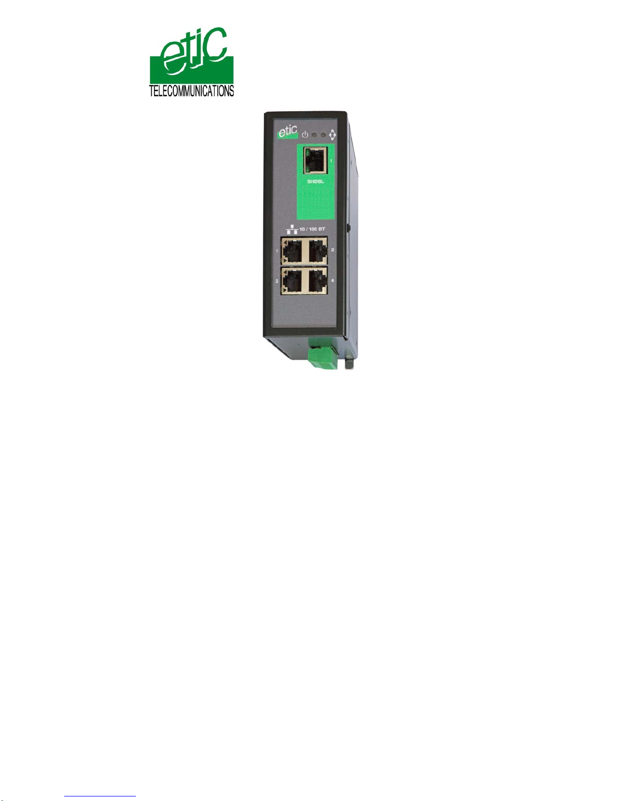
XSLAN
SHDSL switch
_________________
User’s guide
Document reference : 9014709-02
_________________
Page 2

The XSLAN SHDSL switch is manufactured by
ETIC TELECOM
13 Chemin du vieux chêne
38240 MEYLAN
FRANCE
TEL : + 33 4-76-04-20-00
FAX : + 33 4-76-04-20-01
e-mail : [email protected]
web : www.etictelecom.com
Hotline
TEL : + 33 4-76-04-20-05
FAX : + 33 4-76-04-20-01
e-mail : [email protected]
Page 3

CONTENT
XSLAN SHDSL switch User’s guide ref 9014709-02 Page 3
OVERVIEW
1
PRODUCTS IDENTIFICATION...........................................................................6
2 PRODUCT OVERVIEW.......................................................................................7
2.1 Function..................................................................................................7
2.2 Data rate versus distance.....................................................................7
2.3 Ethernet ports........................................................................................8
2.4 VLAN.......................................................................................................8
2.5 Quality of service...................................................................................8
2.6 Serial gateway........................................................................................8
2.7 Diagnostic functions.............................................................................8
2.8 Html or DIP switches configuration....................................................8
3
DATA-SHEET......................................................................................................9
INSTALLATION
1
PRODUCT DESCRIPTION...............................................................................11
1.1 Leds.......................................................................................................12
1.2 Connectors...........................................................................................13
1.3 DIP switches and push-button...........................................................15
2 VENTILATION...................................................................................................16
3 SUPPLY VOLTAGE..........................................................................................16
4 FUSE.................................................................................................................16
5 ETHERNET PORTS..........................................................................................16
6 RS232 (XSLAN—1220, 1230, 2220 AND -2230) .............................................17
7 RS485 (XSLAN-1230 OR -2230)......................................................................17
8 SHDSL LINE.....................................................................................................18
9 INPUT AND OUTPUT.......................................................................................20
../..
Page 4

CONTENT
Page 4 User’s guide ref 9014709-02 XSLAN SHDSL switch
DIP SWITCHES CONFIGURATION
1 OVERVIEW.......................................................................................................21
2 ONE TWISTED PAIR SHDSL LINE SET UP....................................................21
3 TWO TWISTED PAIRS SHDSL LINE SET UP.................................................23
4 TESTING THE SHDSL CONNECTION AND ADJUSTING THE DATA RATE24
HTML CONFIGURATION
1
SET UP STEPS.................................................................................................25
2 ENABLING HTML CONFIGURATION .............................................................26
3 CONNECTING A PC TO THE XSLAN FOR CONFIGURATION.....................26
3.1 Overview...............................................................................................26
3.2 First configuration...............................................................................27
3.3 Modifying the configuration from the LAN........................................28
4 REBOOTING THE XSLAN AFTER PARAMETERS CHANGES.....................28
5 RECOVERING THE FACTORY LAN IP ADDRESS ........................................28
6 RECOVERING THE FACTORY CONFIGURATION.......................................29
7 RESTRICTING ACCESS TO THE ADMINISTRATION SERVER....................29
8 RECOVERING A FREE ACCESS TO THE ADMINISTRATION SERVER......29
9 ASSIGNING AN IP ADDRESS TO THE LAN INTERFACE.............................30
10 IP ROUTING AND BROADCAST FILTERING................................................30
11 ONE TWISTED PAIR SHDSL CONNECTION SET UP....................................33
11.1 Set up....................................................................................................33
11.2 Testing the SHDSL connection and adjusting the data rate...........34
12 TWO WISTED PAIRS UP SHDSL CONNECTION SET UP.............................35
12.1 SHDSL port set up...............................................................................35
12.2 Testing the SHDSL connection and adjusting the data rate...........36
../..
Page 5

CONTENT
XSLAN SHDSL switch User’s guide ref 9014709-02 Page 5
… HTML CONFIGURATION
13
VLAN SET UP...................................................................................................37
13.1 Overview...............................................................................................37
13.2 VLAN set up .........................................................................................39
14 QUALITY OF SERVICE (QOS) SET UP..........................................................40
14.1 DiffServ benefits & overview..............................................................40
14.2 QoS set up............................................................................................41
15 SNMP SET UP..................................................................................................43
16 SERIAL GATEWAY SET UP............................................................................44
16.1 Modbus gateway..................................................................................45
16.2 RAW TCP gateway...............................................................................50
16.3 RAW UDP gateway ..............................................................................53
16.4 Multicast gateway................................................................................55
16.5 Unitelway gateway...............................................................................57
17 DIAGNOSTIC MENU ........................................................................................58
Appendix 1 : Data rate versus distance and cable quality
Appendix 2 : Html server description
Page 6

INSTALLATION
Switch Shdsl XSLAN Notice d’utilisation ref 9014309-01 page 6
1 Products identification
XSLAN SHDSL switch
1400 1220 1230 2400 2220 2230
SHDSL ports
1 1 1 2 2 2
Maximum data rate (Mb/s)
2.3 2.3 2.3 4.6 4.6 4.6
10-100 Mb/s Ethernet ports
4 2 2 4 2 2
RS232
0 1 2 0 1 2
RS485
0 1 0 0 1 0
Basic IP routing feature
Yes Yes Yes Yes Yes Yes
VLAN
Yes Yes Yes Yes Yes Yes
Quality of service
Yes Yes Yes Yes Yes Yes
Gateway
(Raw, telnet, modbus,
unitelway)
0 2 2 0 2 2
Line cable *
1 1 1 2 2 2
Χ The product is delivered with Cable ref. CAB614 for
connection to the line (Qty 1 or 2)
Page 7
INSTALLATION
2 Product overview
2.1 Function
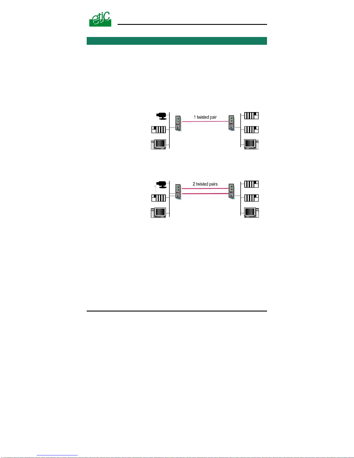
The XSLAN shdsl switch enables to extend an Ethernet network over
kilometers using one or two simple voice-grade twisted pairs (telephone
lines).
The XSLAN-1400 or 1220 or 1230 come with one SHDSL interface; they
can be connected to a one twisted pair line.
They feature up to 2.3 Mb/s.
One pair operation
up to 2.3 Mb/s
XSLAN-1400
XSLAN-1220
XSLAN-1230
The XSLAN-2400 or 2220 or 2230 come with two SHDSL interfaces; they
can be connected to a two twisted pair line.
They feature up to 2.3 Mb/s.
Two pairs operation
up to 4.6 Mb/s
XSLAN-2400
XSLAN-2220
XSLAN-2230
2.2 Data rate versus distance
Each interface features an adaptive data rate from 128 Kb/s up to 2.3
Mb/s.
The data rate is a function of the cable quality and the distance with the
next SHDSL switch. For instance, the maximum distance between 2
switches through a line is 13 Km (8 miles) with a 0.9 mm wire diameter
cable.
The table in appendix 1 gives the data rate which can be expected over a
line versus the length of the line.
XSLAN SHDSL switch User’s guide ref 9014709-02
Page 7
Page 8

INSTALLATION
Page 8 User’s guide ref 9014709-02 XSLAN SHDSL switch
2.3 Ethernet ports
The XSLAN provides 2 or 4 Ethernet RJ45 interfaces (depending on the
product reference).
2.4 VLANs
The XSLAN features VLAN per port :
Each Ethernet port can be assigned to a particular VLAN. A device
connected to an Ethernet port belonging to a particular VLAN can
communicate only with devices connected to Ethernet ports belonging to
the same one.
2.5 Quality of service
The product provides “DiffServ” quality of service functionality to give
transmission priority to critical applications.
Devices TCP ports and IP addresses are classified in 4 priority classes.
A minimum and a maximum bandwidth is allocated to each class.
2.6 Serial gateway
The XSLAN –1220, -1230, -2220 or –2230 feature a 2 ports serial
gateway.
The gateway features raw TCP client and server, raw UDP, modbus
client and server, telnet and multicast.
2.7 Diagnostic functions
The XSLAN html server provides diagnostic pages giving the guarantee
the transmission quality is what it has to be.
2.8 Html or DIP switches configuration
The XSLAN can be configured either with an html browser if advanced
functions are necessary (QoS, RS gateway, diagnostic …).
It can be configured with a few DIP switches for simple unmanaged
applications.
Page 9

INSTALLATION
XSLAN SHDSL switch User’s guide ref 9014709-02 Page 9
3 Data-sheet
Dimensions 137 x 48 x 116 mm (h, l, d)
C.E.M EN50082-2
Electrical safety EN 60950
Lightning EN61000-4 et –5
Supply voltage XSLAN-1400 or –2400 or –1230 or –2230 : 9 to 60 VDC
XSLAN-1220 –2220 : 9 to 30 VDC
Consumption 4W
Operating T° -20°/ + 60°C non condensing
SHDSL ITU-T G.991.2, 802.3ah : 2BaseTL (EFM)
Data rate : 128 kb/s to 2.3 Mb/s with 2 wires
Latency : 4 ms
Ethernet 10/100 Mb/s Half / Full duplex Auto MDI/MDIX
Switch Store and forward – 1024 MAC @
IP Routing Static routes
RIP V2
QoS DiffServ compliant with RFC 2474, 2475, 2597, 2598
4 priority levels (premium, gold, silver, bronze)
SNMP SNMP V2 – MIBII and traps
VLAN Per port
RS232-RS485 1200 to 115200 kb/s parity E/O/N
Raw TCP client and server
Raw UDP
Multicast
Modbus client and server
Unitelway
Telnet
Logs 300 events (date & time)
Configuration Managed mode : HTML browser
Unmanaged mode : DIP switches
Page 10

Page 11
INSTALLATION
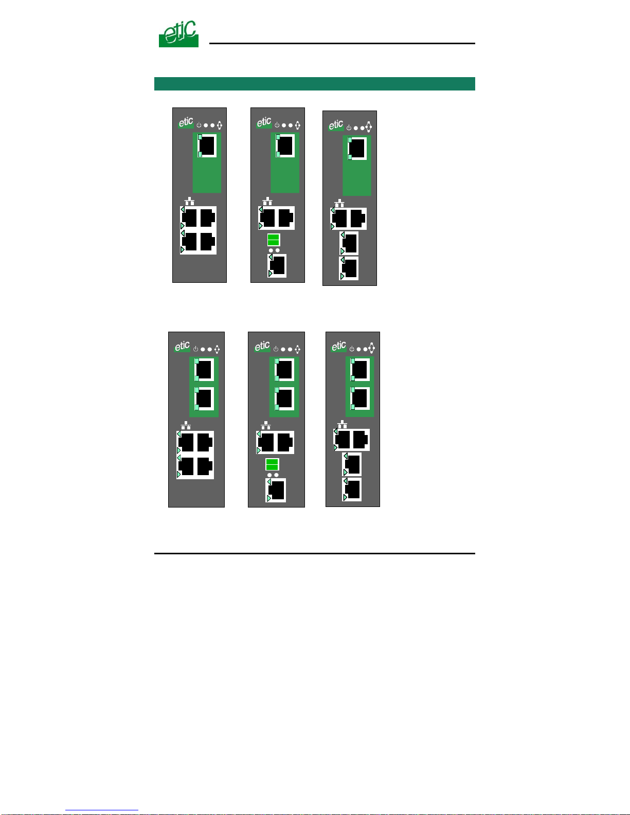
1 Product description
10 / 100 BT
1
2
SHDSL
1
3
4
1
10 / 100 BT
1
2
RS485
RS232
Rx Tx
SHDSL
1
1
10 / 100 BT
1
2
RS232
SHDSL
1
2
RS232
1
XSLAN-1400 XSLAN-1220 XSLAN-1230
10 / 100 BT
1
2
SHDSL
1
3
4
2
10 / 100 BT
1
2
RS485
RS232
Rx Tx
SHDSL
1
1
1
10 / 100 BT
1
2
RS232
SHDSL
1
2
2
RS232
1
XSLAN-2400 XSLAN-2220 XSLAN-2230
Switch Shdsl XSLAN Notice d’utilisation ref 9014309-01
page 11
Page 12
INSTALLATION
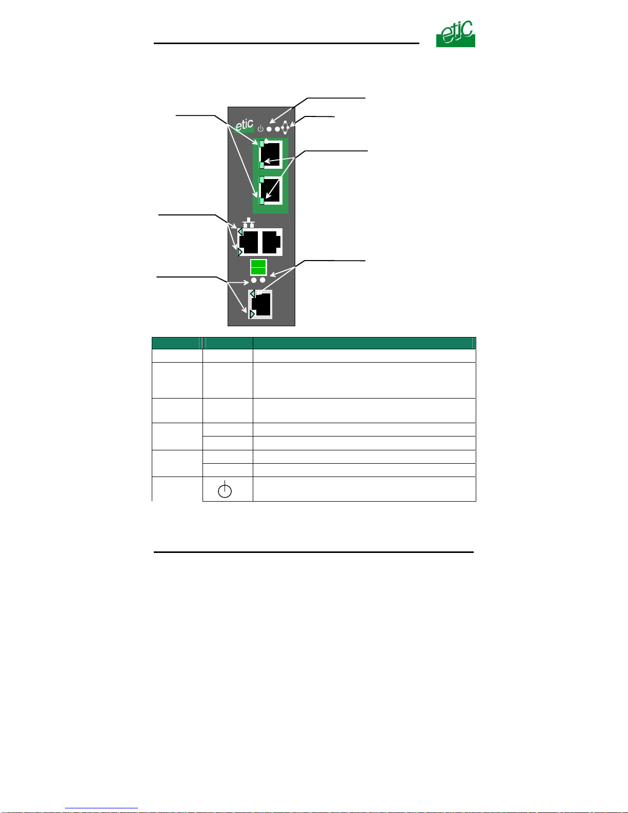
1.1 Leds
10 / 10 0 BT
1
2
RS232
SHDSL
1
2
RS485
Not used
OPERATIO N le d
Ethernet activity led
port 1 & port 2
SHDSL Errors
port 1 & port 2
RX led
(to the XSLAN)
TX led
(from the XSLAN)
RS485
Rx
Tx
SHDSL connection
leds
Function Led Description
Ethernet
LINK/DATA
Ethernet activity
Shdsl led
(Lower)
Slowly blinking : Shdsl connection in process
Lit on : Shdsl connection set
Quickly blinking : Traffic over the SHDSL link
Line
Shdsl led
(Upper)
Error
Off : Error-free transmission
Quickly blinking : Transmission errors
RS232
Rx
Bytes received from the RS232 (to XSLAN)
Tx
Bytes transmitted to the RS232 (from XSLAN)
RS485
Rx
Bytes received from the RS485 (to XSLAN)
Tx
Bytes transmitted to the RS485 (from XSLAN)
Operation
Green : Ready for use
Red : Alarm
Page 12 User’s guide ref 9014709-02 XSLAN SHDSL switch
Page 13
INSTALLATION
XSLAN SHDSL switch User’s guide ref 9014709-02 Page 13
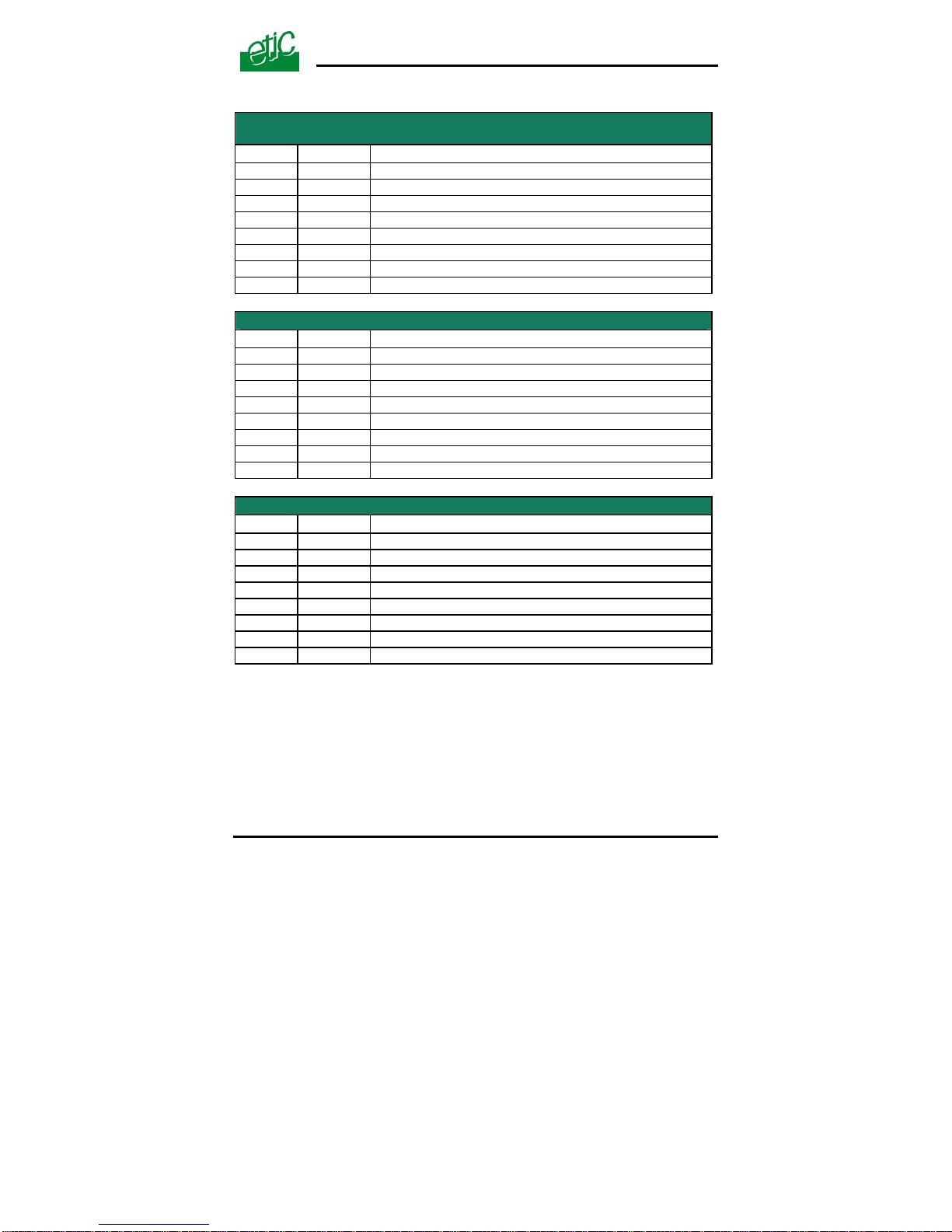
1.2 Connectors
8 pins screw block
Supply voltage and input / output
Pin Nr Signal Function
1 Power 1 + Supply voltage input 1
2 Power 1 - 0 V
3 Power 2 + Supply voltage input 2
4 Power 2 - 0 V
5 3V3 + 3.3 VDC voltage provided by the product
6 In Input
7 F + Output + (max 48Vdc - 0,5A)
8 F - Output -
SHDSL RJ45 connector
Pin Nr Signal Function
1 N.C. 2 N.C. 3 N.C. 4 TIP SHDSL line
5 RING SHDSL line
6 N.C. -
7 N.C. 8 N.C. -
Ethernet RJ45 connector
Pin Nr Signal Function
1 Tx + TX polarity +
2 Tx - TX polarity 3 Rx + Reception polarity +
4 N.C 5 N.C 6 Rx - Reception polarity 7 N.C. 8 N.C. -
Page 14
INSTALLATION
Page 14 User’s guide ref 9014709-02 XSLAN SHDSL switch
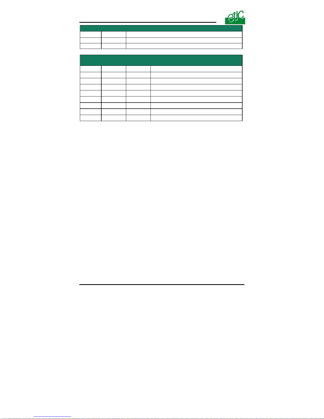
RS485 2 pins screw block
Pin Nr Signal Function
1 A RS485 polarity A
2 B RS485 polarity B
RS232 RJ45 connector
(To connect to a DCE)
Pin Nr Circuit Function
1 DTR - 108 Out
Data terminal ready
2 TD - 103 Out
Data Emission
3 RD - 104 IN
Data Reception
4 DSR - 107 IN
Data set ready
5 SG - 102 -
Ground
6 Not used Out
-
7 CTS - 106 IN
Clear to send
8 RTS - 105 Out
Request to send
Page 15
INSTALLATION
XSLAN SHDSL switch User’s guide ref 9014709-02 Page 15
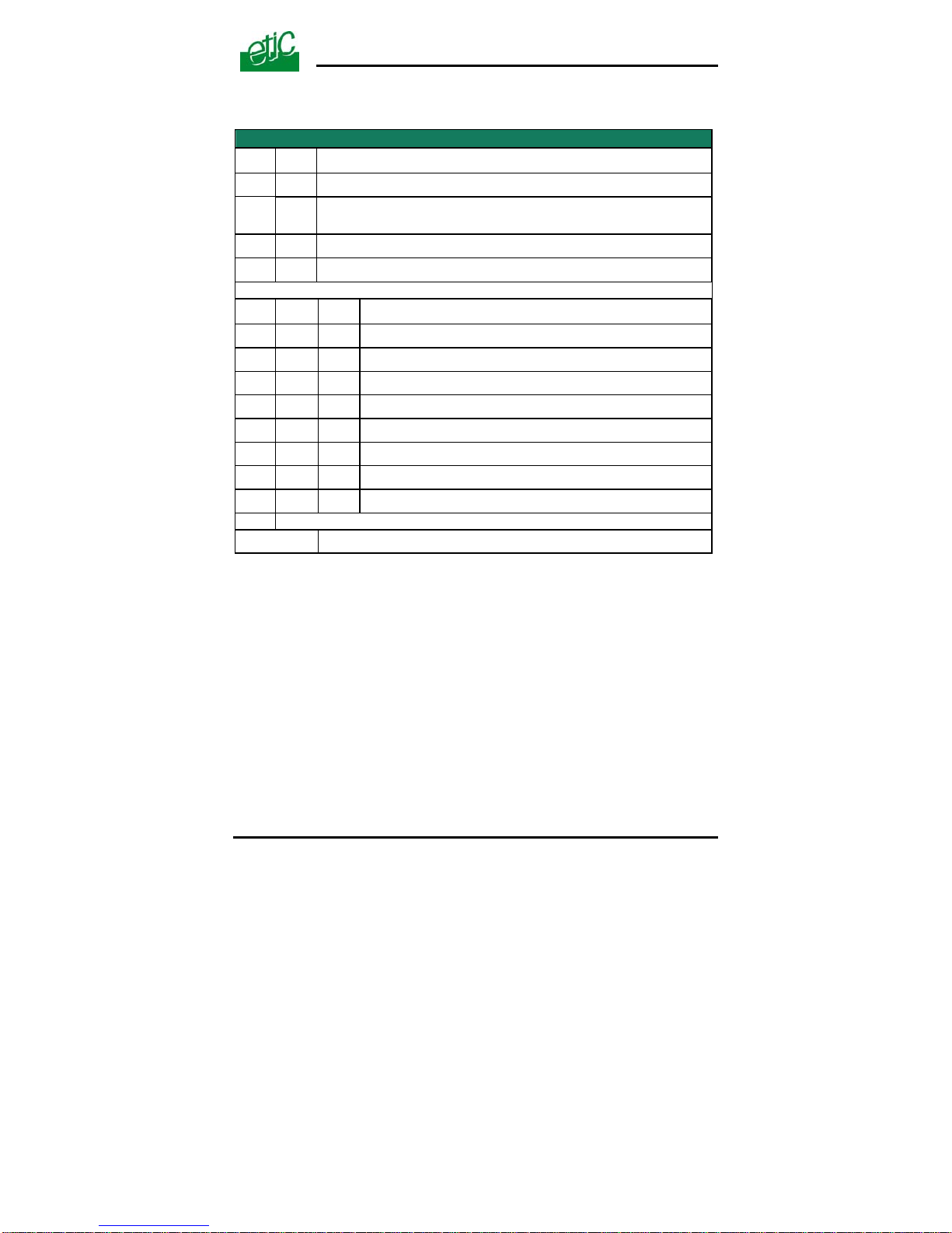
1.3 DIP switches and push-button
DIP switches
SW 1 SW 2
Management
OFF OFF
The current IP@ of the product is the stored IP @
ON OFF
The active IP@ of the product is the factory IP@ : 192.168.0.128
No login and password are required to access to the html server
OFF ON
The active IP@ is provided by the BOOTP or DHCP server
ON ON
No IP @ is assigned to the product; DIP switch configuration
SW 3 SW 4 SW 5
Shdsl port 1
OFF OFF OFF
NTU mode
OFF OFF ON
LTU mode - Auto
OFF ON OFF
LTU mode – 2304 kbit/s
OFF ON ON
LTU Mode – 2048 kbit/s
ON OFF OFF
LTU Mode – 1536 kbit/s
ON OFF ON
LTU Mode – 1024 kbit/s
ON ON OFF
LTU Mode – 512 kbit/s
ON ON ON
LTU Mode – 256 kbit/s
SW 6 to SW 12
Not used - Must be left OFF
Push-button :
A push-button is located close to the DIP switches.
It enables to restore the factory profile.
To restore the factory profile, switch the power on while pressing the
push-button until the OPERATION led turns green.
Attention : Once the factory profile has been restored, the stored
configuration is lost.
Page 16

INSTALLATION
Page 16 User’s guide ref 9014709-02 XSLAN SHDSL switch
2 Ventilation
To avoid overheating when the ambient temperature is high, leave a 1 cm
(0.5 inch) space on each side of the product.
3 Supply voltage
The product comes with 2 separate voltage inputs, so that 2 external
power supply modules can be connected to the product. If one power
supply module fails, the XSLAN will be powered by the other.
The supply voltage must be
• strictly lower than 60 VDC and higher than 9 VDC for XSLAN—
1400, -2400, -1230, -2230.
• strictly lower than 30 VDC and higher than 9 VDC for XSLAN1220 or –2220.
The consumption is 170 mA at 24 VDC.
4 Fuse
The product is protected with a 3A fuse located on the electronic board
near the supply voltage connectors.
!!! A replacement fuse is available on the board ; it is located over the leds.
5 Ethernet ports
The XSLAN features two or four auto-sensing 10/100 Mbps MDI/MDI-X
LAN ports.
Page 17
INSTALLATION
6 RS232 (XSLAN—1220, 1230, 2220 and -2230)
The RS232 data rate can be tuned from 1200 to 115200 b/s with parity
(even / odd) or no parity.
The data terminal must be less than 10 meters far from the modem.
Cables can be provided to connect the product to DTE and DCE as
follows :
RS232 cables (L=1m)
Code User connector Cable function
CAB592 SubD 9 male T o connect a DCE to the XSLAN
CAB593 SubD 9 female To connect a DTE to the XSLAN
CAB609 wires To connect a device providing a specific
connector
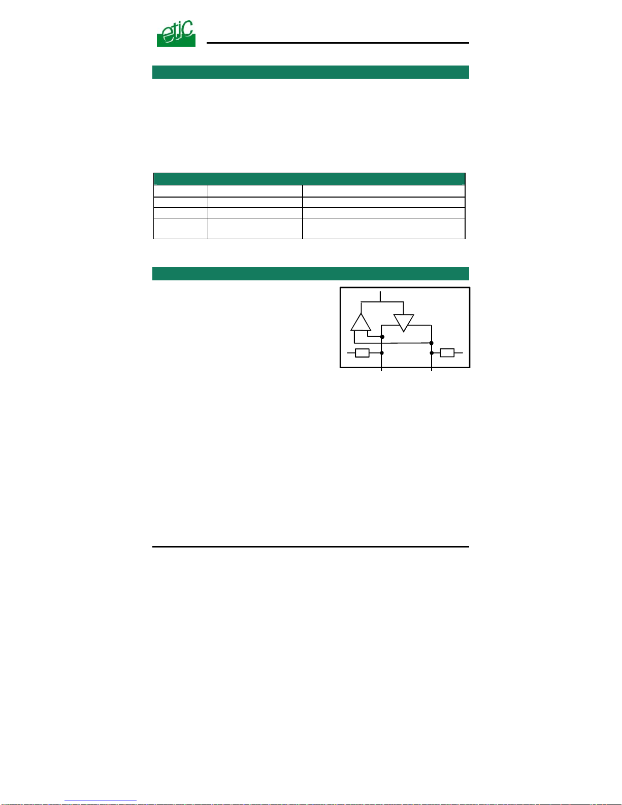
7 RS485 (XSLAN-1230 or -2230)
The RS485 serial interface is
provided on the front panel 2 pins
screw-block.
Polarisation resistors
1 Kohm bus polarisation resistors
are included inside the product.
-
1K 1K
+
SW1
B(+) A(-)RS485
RS485 line adaptation
For a several meters long connection over the RS485 local interface, it is
not necessary to adapt the RS485 line. For a longer distance, connect a
120 Ohm resistor at each end of the line.
XSLAN SHDSL switch User’s guide ref 9014709-02
Page 17
Page 18
INSTALLATION
8 SHDSL line
Remark :
For test purpose on a desk, the line can be replaced by any Ethernet
straight cable.
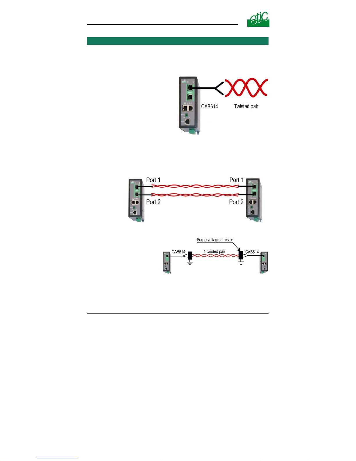
Connecting the XSLAN to the
line
The CAB614 cable allows to
connect the XSLAN to the line.
The cable comes with 2 wires
which have to be connected to
the two wires of the twisted p air.
he 2 wires can be inverted. T
Case of a two twisted pairs connection
ted with two pairs instead of only one.
DSL switch must be necessarily connected to the port Nr 1 of
The XSLAN-2400 or –2220 or –2230 can be connec
The data rate is doubled.
The port Nr 1 of the first SH
the other switch.
urge voltage arrester
e
S
if the line is exposed to th
lightning, we advise to use
an over voltage arrester at
each end of the line.
Page 18 User’s guide ref 9014709-02 XSLAN SHDSL switch
Page 19

INSTALLATION
We have selected the Phoenix Contact
module TT-2-PE-24D; it must be wired as
indicated opposite.
Line cable shield :
If the line is shielded, the shield must be connected to the earth; only at
one end if it is not interrupted along the line.
XSLAN SHDSL switch User’s guide ref 9014709-02
Page 19
Page 20
INSTALLATION
9 Input and output
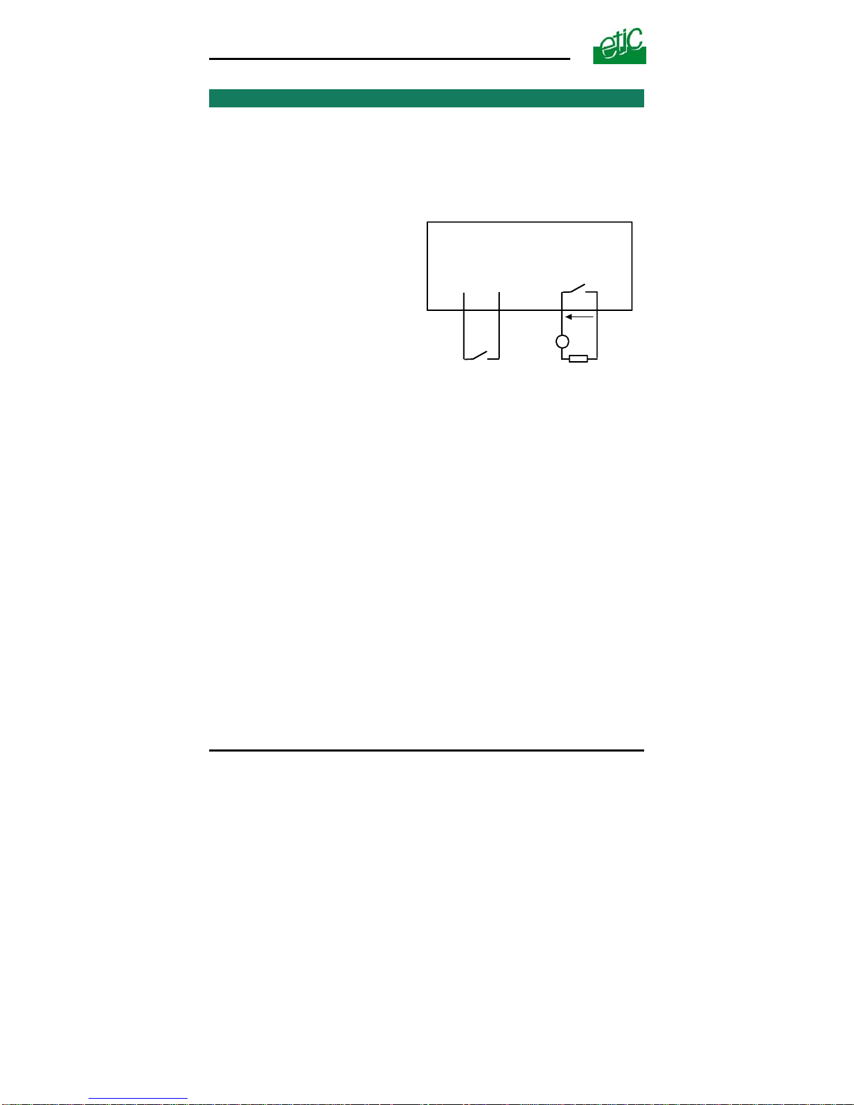
Input
That input is not isolated.
if it is opened, an SNMP trap will be sent to the SNMP server is that
function has been enabled.
Alarm output
1 relay output is provided to indicate
an alarm.
F+ F-
7
8
Digital output
+
V < 48 VDC
I < 0,5 A
3V3
In
5
6
Digital input
I max = 0,5 A
V
The alarm condition can be
selected using the html server.
The Output is open when the
XSLAN is switched OFF or when
the SHDSL line is not connected.
Page 20 User’s guide ref 9014709-02 XSLAN SHDSL switch
Page 21
DIP-SWITCHES SET UP
1 Overview
The XSLAN can be configured either with DIP switches or with an html
browser through Ethernet.
The DIP switch configuration is very simple; it will be preferred when the
distance is under the limit of the product and when only simple functions
are required.
The Html server set up is mandatory
when the distance between two SHDSL switches is close to the limit
to take advantage of the Diagnostic functions,
or when advanced functions like VLAN, Quality of Service, serial
gateways, which can only be configured with the html server, are
required.
2 One twisted pair SHDSL line setup
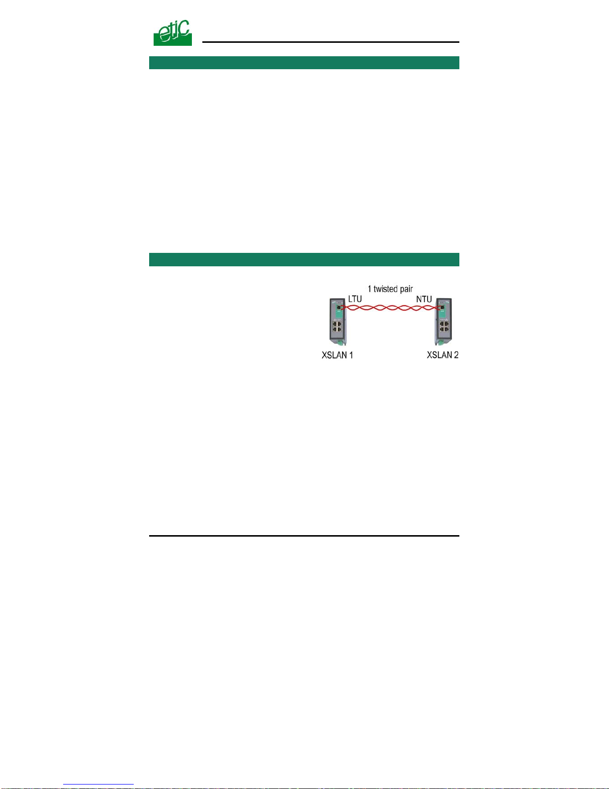
When two XSLAN SHDSL switches a
connected through a 1 twisted pair line,
the port of the first one has to be set as
an LTU (calling party) and the port of
the other one has to be configur
an NTU (called party).
re
ed as
The SHDSL switch port which is named LTU negotiates and forces the
data rate over the line; the NTU can only accept.
The data rate can be either negotiated by the LTU itself (auto mode) , or
imposed by the user with the DIP switches.
Switch Shdsl XSLAN Notice d’utilisation ref 9014309-01
page 21
Page 22

DIP SWITCHES SET UP
Page 22 User’s guide ref 9014709-02 XSLAN SHDSL switch
•
XSLAN Nr 1 setup
Setup the XSLAN Nr 1 as a LTU and set the data rate :
SW1 & SW2
Setup DIP switches SW1 an SW2 ON to enable DIP switches operations.
SW3, SW4, SW5
Set the XSLAN Nr 1 as a LTU and select the data rate according to the
distance and the cable quality (see appendix 1).
•
XSLAN Nr 2 setup
Setup the XSLAN Nr 2 as a NTU
SW1 & SW2
Set up DIP switches SW1 an SW2 ON to enable DIP switches operations.
SW3, SW4, SW5
Set SW3, SW4, SW5 OFF.
Page 23
DIP-SWITCHES SET UP
3 Two twisted pairs SHDSL line set up (XSLAN-2400, 2220, 2230)
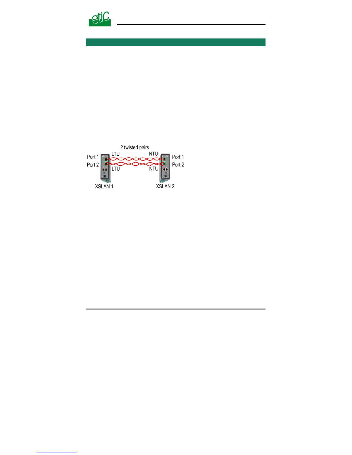
When two XSLANs SHDSL switches are connected through a 2 twisted
pairs line,
up to 4,6 Mb/s instead of 2,3 Mb/s can be provided;
The data flow is automatically shared over the two pairs;
both ports of the XSLAN Nr 1 have to be set as a LTU (calling party)
and both ports of the other one have to be configured as an “NTU”.
(called party).
The DIP switches allow to set up the port 1. Once the port 1 has been set
up with the DIP switches, the port 2 is then automatically set up by the
product itself.
• XSLAN Nr 1 set up
SW1 & SW2
Set up DIP switches SW1 an SW2 ON to enable DIP switches operations.
SW3, SW4, SW5
Set the XSLAN Nr 1 as a LTU and select the data rate according to the
distance and the cable quality (see appendix 1).
•
XSLAN Nr 2 set up
SW1 & SW2
Set up DIP switches SW1 an SW2 ON to enable DIP switches operations.
SW3, SW4, SW5
Set SW3, SW4, SW5 OFF to set up the XSLAN Nr 2 as a NTU.
XSLAN SHDSL switch User’s guide ref 9014709-02
Page 23
Page 24

DIP SWITCHES SET UP
Page 24 User’s guide ref 9014709-02 XSLAN SHDSL switch
4 Testing the SHDSL connection and adjusting the data rate
• Connect two SHDSL switches to the line and power them up.
Remark :
For test purpose on a desk, the line can be replaced by any Ethernet
straight cable.
The line led of the RJ45 SHDSL connector (it is the lower led) blinks
during the connection phase (45 seconds more or less) and lights on
when the connection is established.
• Test the error rate by pinging remotely one of the devices connected to
the other XSLAN.
• If the Ping error rate is not close to 0%, modify the setting of the LTU
(XSLAN Nr 1).
Decrease the data rate using the DIP switches SW3, SW4, SW5.
Page 25

HTML SET UP & DIAGNOSTIC
XSLAN SHDSL switch User’s guide ref 9014709-02 Page 25
Setting-up the XSLAN with the Html server is mandatory
when the distance between two SHDSL switches is close to the limit
to take advantage of the Diagnostic functions,
or
when advanced functions like VLAN, Quality of Service, SNMP, serial
gateways, which can only be configured with the html server, are
required.
1 Set up steps
To configure the XSLAN, we advise to proceed as follows :
• Connect a PC to the router
• Set up the LAN interface
• Set up IP routing and broadcast filtering
(option)
• Set up the SHDSL connection
• Set up VLAN
• Set up Quality of service
• Set up SNMP
• Set up the serial gateway
Page 26

HTML SET UP & DIAGNOSTIC
Page 26 User’s guide ref 9014709-02 XSLAN SHDSL switch
2 Enabling html configuration
Coming from factory, the DIP switches SW1 and SW2 are set OFF (ready
for html configuration); and the IP address of the XSLAN is
192.168.0.128.
Check the DIP switches SW1 and SW2 are OFF.
Remark :
When the DIP switches SW1 and SW2 are OFF, the active IP address is
the stored IP address.
3 Connecting a PC to the XSLAN for configuration
3.1 Overview
Administration server address :
The administration html server is located at the LAN IP address of the SHDSL switch (The
factory IP address is192.168.0.128).
First set up :
For the first configuration, we advise to connect the PC directly to the LAN interface of the
SHDSL switch..
Further set up modifications :
Modifications can be carried out from the LAN interface, or remotely through the line.
Restoring the factory IP address :
The factory IP address of the router on the LAN interface can be restored by setting the
DIP switches SW01 ON and SW02 OFF.
In that position of the DIP switches, the stored configuration is not deleted.
Setting the DIP switches in that position gives also a free access to the administration
server from the LAN interface.
During operations, the DIP switches must not be left in that position.
Network IP address :
Later in the text, we often speak of “network IP address”.
We mean the lowest value of the addresses of the network.
For instance, if the netmask of a network is 255.255.255.0, the network IP address of that
network is X.Y.Z.0.
Page 27
HTML SET UP & DIAGNOSTIC
Copy and paste :
Parameters must be entered with the keyboard; they cannot be pasted.
However, it can be useful to paste a string when it is long to avoid errors.
In that case, paste the string, delete the last character of the pasted string, and enter it
again with the keyboard.
Saving and restoring the parameters file (see the maintenance
chapter)
A parameters file can only be downloaded to a product with the same firmware version. It
is why, we advise to assign a name to a parameter file including the product name and the
software version like for instance “my_XSLAN2400_file _V241.bin”.
3.2 First configuration
Step 1 : Create or modify the PC IP connection.
Assign to the PC an IP @ in accordance with the WSRING IP address.
For the first configuration, assign or instance 192.168.0.127 to the PC.
Step 2 : Connect the PC directly
to an XSLAN ethernet interface
using any Ethernet cable (straight
or cross-wired)
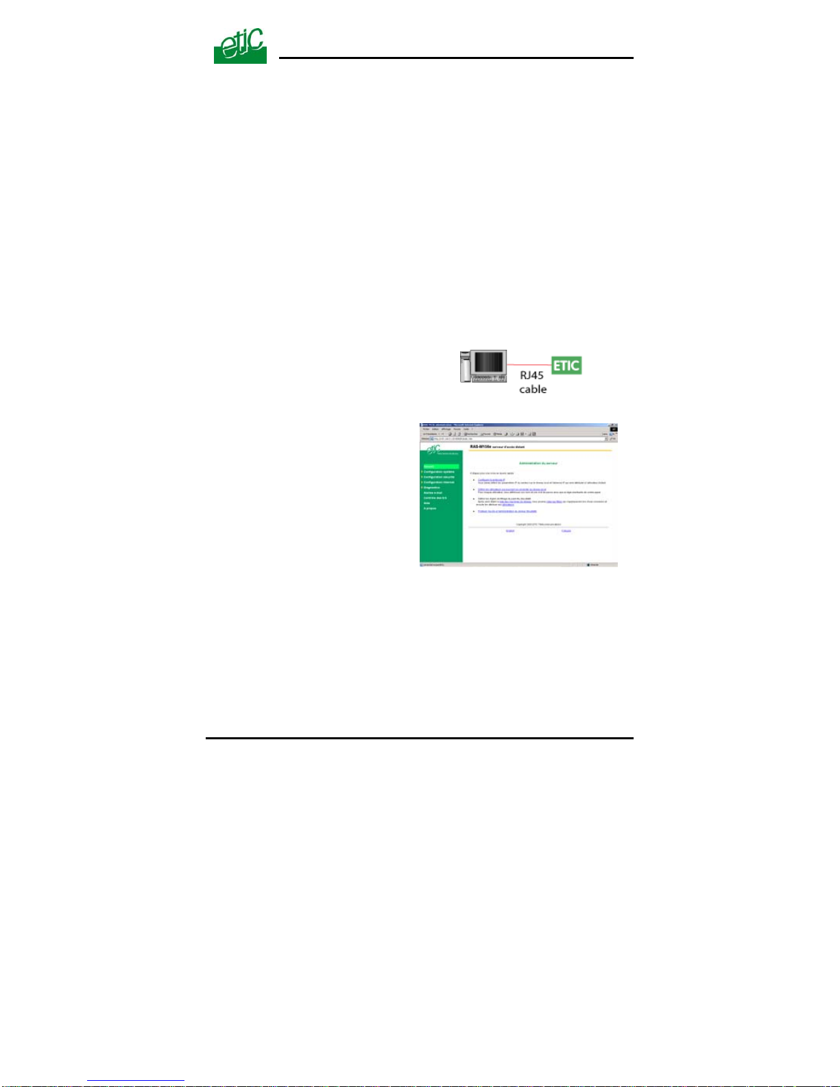
Step 3 : Launch the navigator
Enter the LAN IP @ of the SHDSL
switch192.168.0.128.
The Home page of the
administration server is displayed
Note :
If the home page cannot be displayed, refer to paragraph 4 below.
XSLAN SHDSL switch User’s guide ref 9014709-02
Page 27
Page 28

HTML SET UP & DIAGNOSTIC
Page 28 User’s guide ref 9014709-02 XSLAN SHDSL switch
3.3 Modifying the configuration from the LAN
Step 1 : Ensure the DIP switch SW1 and SW2 are OFF to select the
stored IP @.
Step 2 : Launch the html browser and enter the IP address assigned to
the router.
Or, launch the ETICFINDER utility to detect the XSLAN IP address.
Remark :
If the home page cannot be displayed, refer below.
4 Rebooting the XSLAN after parameters changes
• After the parameters any page have been completed, click the
« Save » button at the bottom of the page.
• After some parameters changes, the IPL-E must restart.
When the configuration has been completely carried out, click the
« Reboot » red button in the green bar, when displayed.
• Once the product has restarted, check the « Reboot » button has
disappeared from the green bar.
To save the configuration file to a hard disk :
• Select the “maintenance” menu and then the “Save / restore” menu.
• Click the “Save current configuration to disk” button.
5 Recovering the factory LAN IP address
When launching the html browser, the homepage of the html server may
not be displayed; the cause may be the IP address you entered was
wrong.
if the IP address you enter is wrong, you can recover the factory IP
address by setting SW01 ON and SW2 OFF.
The factory IP address 192.168.0.128 will be restored as long as the
SW01 and SW02 micro switch will be left in that position.
Page 29
HTML SET UP & DIAGNOSTIC
XSLAN SHDSL switch User’s guide ref 9014709-02 Page 29
Remark :
The SW01 and SW02 must not be left in that position during operations.
6 Recovering the factory configuration
For any reason, it may be necessary to restore the factory configuration of
the SHDSL switch.
To restore the factory configuration,
• Switch OFF the power supply.
• Press the push button on the top part of the IPL-E router and switch
ON the power supply.
• Keep the push button pressed until the Operation led turns red.
Remark : The stored configuration will be lost; the factory IP address
192.168.0.128 will be restored.
7 Restricting access to the administration server
The access to the administration server can be protected by a login and
password.
To protect access to the administration server,
• Select the “System” menu, and then the “Administration rights” menu.
8 Recovering a free access to the administration server
If the Login & or password entered to reach the administration server
have been rejected, it is possible to recover a free access to the
administration server from the LAN only, by setting SW01 ON and SW2
OFF.
Remark :
The factory IP address 192.168.0.128 will also automatically be restored
as long as SW01 will remain ON and SW2 OFF.
During normal operations SW01 and SW02 must not be left in that
position.
Page 30
HTML SET UP & DIAGNOSTIC
9 Assigning an IP address to the LAN interface
An IP address must be assigned to that interface.
The HTML server is located at that IP address.
To assign an IP address to the LAN interface,
• select the “IP protocol and IP routing” menu and then the IP menu;
• enter the IP address, the netmask and the default gateway address.
10 IP routing and broadcast filtering
The SHDSL XSLAN switch is an Ethernet switch; it works like any usual
switch and it is able to transmit any upper level protocol.
It is why, generally, it is not necessary to enable the IP routing function.
However, the IP routing feature can be used in particular cases, to avoid
to transfer multicast or broadcast frames or other traffic towards the
SHDSL link.
In that case, to make IP routing possible,
1. The SHDSL network has to be set as an IP network. An IP address
must be assigned to the SHDSL interface of the XSLAN.
Remark : if the XSLAN provides two SHDSL interfaces (XSLAN-400, -
2220, -2230); the same IP address has to be assigned to both.
2. The network connected to the LAN interface of the XSLAN must be a
different IP network from the SHDSL IP network and from other networks.
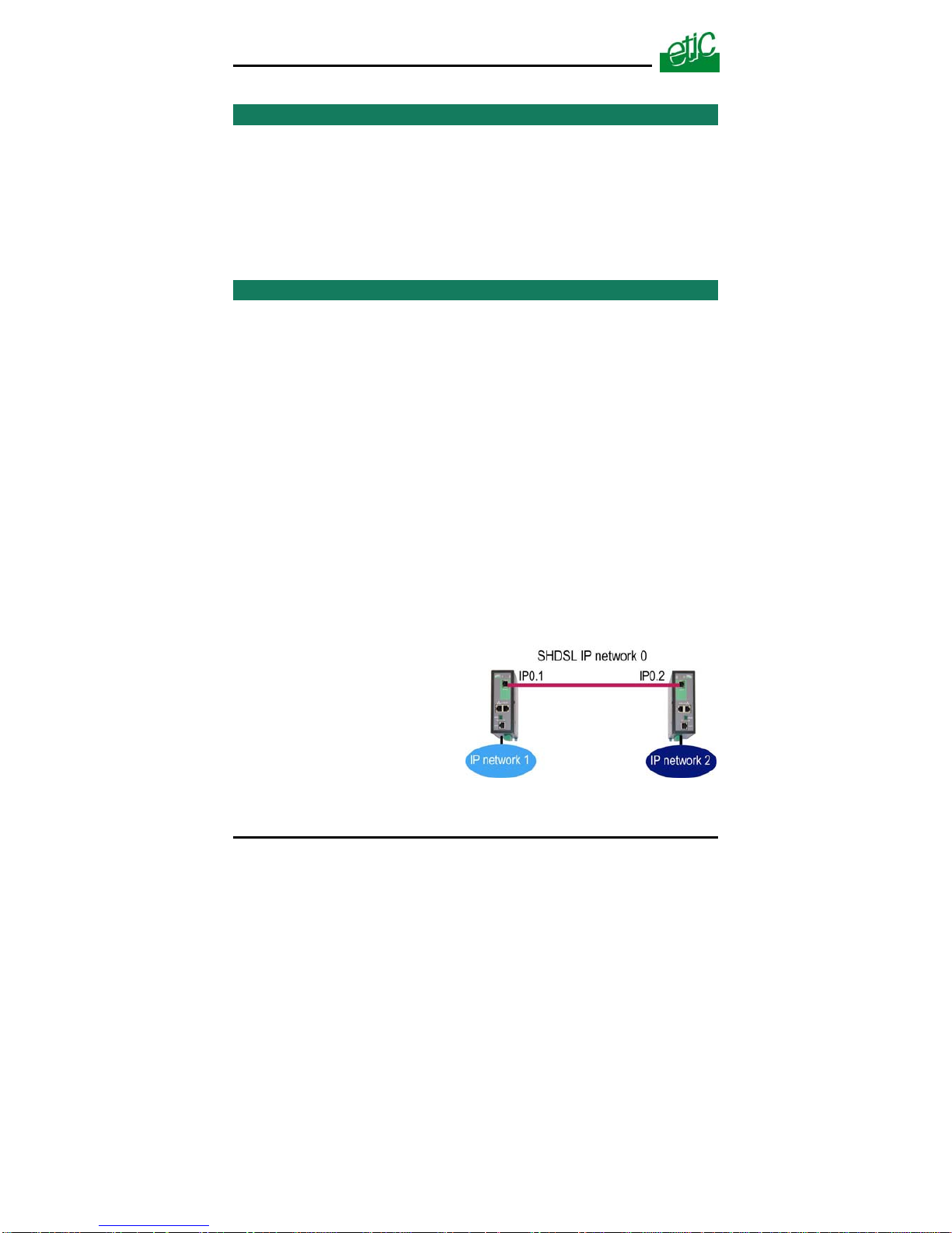
For instance, referring to the
drawing below, if the XSLAN Nr 1
is used as a router, the IP @ of
the network 1 must be different
from the IP @ of the SHDSL
network and from network 2
3. Routes must be created or the RIP protocol must be enabled.
Page 30 User’s guide ref 9014709-02 XSLAN SHDSL switch
Page 31

HTML SET UP & DIAGNOSTIC
XSLAN SHDSL switch User’s guide ref 9014709-02 Page 31
A route is a table which registers which gateway address must be used to
transfer IP packets to a particular network.
For instance, referring to the drawing above, if IP packets have to be
transmitted from the IP network 1 to the IP network 2, a route has to be
created as follows :
Route name : “From NETWK 1 to NETWK 2”
Destination IP addr : “network 2 IP address”
Gateway IP addr : IP02
Remarks :
“Network 2 IP address” is the address of the network Nr 2; for instance
192.168.2.0.
IP02 is the address of the SHDSL interface of the XSLAN Nr 2.
To enable the routing function and assign an IP @ to the SHDSL
interface,
• select the “IP protocol & routing” menu and then the “IP protocol” menu,
• Select the “Routing mode active” checkbox.
• Enter the IP address, netmask, and, eventually, default gateway assigned to the
SHDSL network.
Page 32
HTML SET UP & DIAGNOSTIC
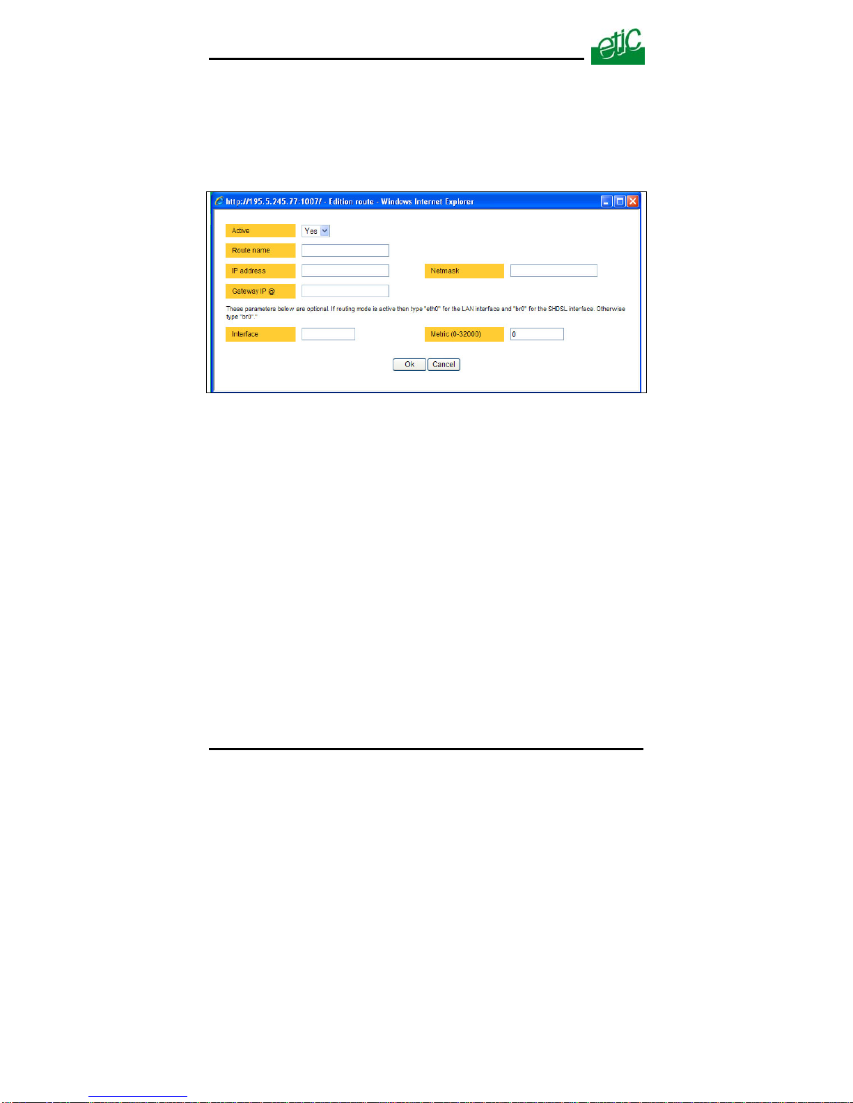
To register a route,
• select the “IP protocol & routing” menu and then the “routing” menu,
• click the ”Add a route” button.
• Enter the parameters of the route.
To enable the RIP protocol instead of programming routes,
• select the “IP protocol” and then the “RIP” menu.
• Select the “Activate” checkbox.
Page 32 User’s guide ref 9014709-02 XSLAN SHDSL switch
Page 33
HTML SET UP & DIAGNOSTIC
11 One twisted pair SHDSL connection set up
11.1 Set up
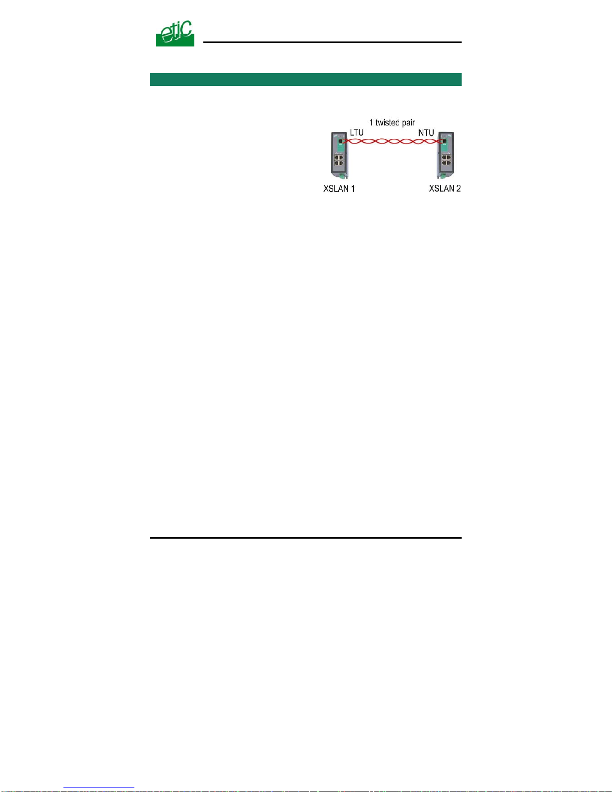
When two XSLAN SHDSL switches a
connected through a line, the port of
the first one has to be set as an LTU
(calling party) and the port of the other
one has to be configured as an “NTU”.
(called party).
re
The SHDSL switch port which is named LTU negotiates and forces the
data rate over the line; the NTU can only accept.
The data rate can be either negotiated by the LTU itself (auto mode) , or
imposed by the user with the DIP switches.
To set up the XSLAN Nr 1
• Select the Ethernet & switching” menu and then the “SHDSL port” menu.
• Select the LTU checkbox.
• Select the data rate according to the table of the appendix 1.
Note : If the “auto” option is selected, it will cause the XSLAN to try all the data rates.
The connection delay will be long. Moreover, the XSLAN software will select a
cautious solution. It is why the “auto” option will be selected only if the distance
is short (less than, 1 Km).
• Select the “Signal power” value “Auto”.
The power of the signal emitted towards the line is normally 14.5 dBm.
It must not be reduced except for very short distance transmission and if
errors appear.
To set up the SHDSL XSLAN switch Nr 2
• Select the NTU checkbox.
• Select the “Signal power” value “Auto”.
XSLAN SHDSL switch User’s guide ref 9014709-02
Page 33
Page 34

HTML SET UP & DIAGNOSTIC
Page 34 User’s guide ref 9014709-02 XSLAN SHDSL switch
11.2 Testing the SHDSL connection and adjusting the data rate
• Connect two XSLANs to a line, check the line led (the lower led of the
SHDSL connector) blinks during the connection (about 45 seconds) and
then lights on.
• If the led blinks endlessly, it means the connection cannot be
established; select a lower data rate.
• Once the connection is established, select the “Diagnostic” menu, and
then the “Network status” menu and then the “Statistics” menu.
Check the “SNR margin” is greater than 6. Otherwise decrease the data
rate.
• Select the “Diagnostic” menu, and then the “Log” menu.
Check the XSLAN remains permanently connected. Disconnections
must be very rare. If disconnections are frequent, check the line itself
and / or decrease the data rate.
Page 35
HTML SET UP & DIAGNOSTIC
12 Two twisted pairs SHDSL connection set up
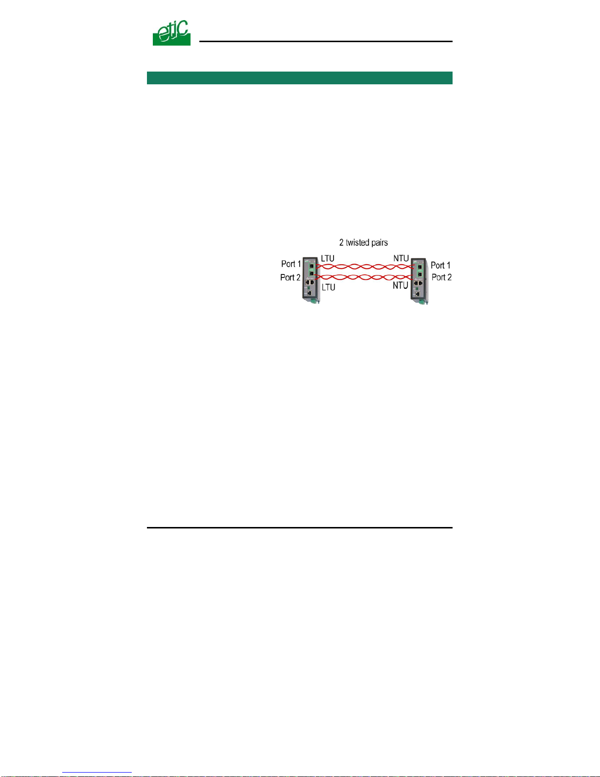
When two XSLANs SHDSL switches are connected through a 2 twisted
pairs line,
up to 4,6 Mb/s instead of 2,3 Mb/s can be provided;
The data flow is automatically shared over the two pairs;
both ports of the XSLAN Nr 1 have to be set as a LTU (calling party)
and both ports of the other one have to be configured as an “NTU”.
(called party).
12.1 SHDSL port set up
Once the XSLANs will have been set
up, they must be connected to the
line according to the drawing
opposite.
Setting up The XSLAN Nr 1
• Select the Ethernet & switching” menu and then the “SHDSL port” menu.
• Select the LTU checkbox for both port 1 and 2.
• Select the data rate according to the table of the appendix 1 for both port 1 and 2.
Note : If the “auto” option is selected, it will cause the XSLAN to try all the
data rates. The connection delay will be long. Moreover, the XSLAN
software will select a cautious solution. It is why the “auto” option will
be selected only if the distance is short (less than, 1 Km).
• Select the “Signal power” value “Auto”.
• Select the “SHDSL ports aggregation” checkbox.
• Save and click the reboot button.
XSLAN SHDSL switch User’s guide ref 9014709-02
Page 35
Page 36

HTML SET UP & DIAGNOSTIC
Page 36 User’s guide ref 9014709-02 XSLAN SHDSL switch
Setting up The XSLAN Nr 2
• Select the Ethernet & switching” menu and then the “SHDSL port” menu.
• Select the NTU checkbox for port 1 and 2.
• Select the “Signal power” value “Auto” for port 1 and port 2.
• Select the “SHDSL ports aggregation” checkbox.
• Save and click the reboot button.
12.2 Testing the SHDSL connection and adjusting the data rate
Proceed as follows for each of the two SHDSL connections.
• Connect two XSLAN to the two twisted pairs, check the line led of
each SHDSL interface (the lower led of each SHDSL connector) blinks
during the connection (45 seconds) and then lights on permanently.
Remark : The LINE leds glitters slightly with the shdsl traffic.
• If the led blinks endlessly, it means the connection cannot be
established; select a lower data rate.
• Once the connection is established, select the “Diagnostic” menu, and
then the “Network status” menu and then the “Statistics” menu.
Check the “SNR margin” is greater than 6. Otherwise decrease the data
rate.
• Select the “Diagnostic” menu, and then the “Logs” menu.
• Check the XSLAN remains permanently connected. Disconnections
must be very rare. If disconnections are frequent, check the line itself
and / or decrease the data rate.
Page 37

HTML SET UP & DIAGNOSTIC
13 VLAN set up
13.1 Overview
VLAN is a flexible group of devices that can be located anywhere in a
network, but than can communicate as if they are on the same physical
segment.
Devices within a VLAN can only communicate directly with devices
belonging to the same VLAN. If a device belonging to VLAN 1 needs to
communicate with devices in VLAN 2, the traffic needs to pass through a
routing device or Layer 3 switch.
An Ethernet frame belonging to a particular VLAN is tagged with a code
which is the VLAN identity code.
Four VLANs are managed by each
XSLAN.
Each Ethernet port of an XSLAN
can be assigned to one of that four
VLANs.
The HTML administration server
and the serial gateway can also be
assigned to one of that four VLANs.
Each RJ45 port can be set up as “Untag” or “Tag” or “Trunk” or “All
access”.
“Untag” port
A port must be set up as “Untag” if the device connected to the port must
only communicate with devices belonging to the same VLAN.
Untagged Ethernet frames entering the port are tagged by the XSLAN
with the VLAN id code before being transmitted to the SHDSL network or
to other ports of the XSLAN.
Tagged Ethernet frames entering the port are transmitted only if they
belong to the right VLAN.
Reciprocally, Ethernet frames coming from the SHDSL network or from
other ports of the XSLAN can be transmitted to the port only if they are
tagged with the right VLAN ID code.
XSLAN SHDSL switch User’s guide ref 9014709-02
Page 37
Page 38

HTML SET UP & DIAGNOSTIC
Page 38 User’s guide ref 9014709-02 XSLAN SHDSL switch
Before being transmitted to the port the Ethernet frames are untagged by
the XSLAN.
”Trunk” port
An Ethernet port must be set up as a “Trunk” port, when that port is used
to connect an SHDSL network to another network like an optical network
for instance.
All tagged Ethernet frames entering the port are transmitted towards the
SHDSL network or other ports.
Untagged Ethernet frames are tagged by the XSLAN with the right VLAN
ID code.
Reciprocally, all tagged Ethernet frames coming from the SHDSL network
are transmitted to that port. They are not untagged by the XSLAN.
Untagged Ethernet frames are tagged by the XSLAN with the right VLAN
ID code.
“Tag” port
An Ethernet port must be set up as a “Tag” port, when the device
connected to that port tags the Ethernet frames by itself.
Ethernet frames entering the port are transmitted towards the SHDSL
network or other ports only if they are tagged with one of the four VLAN ID
codes registered by the XSLAN.
Reciprocally, Ethernet frames coming from the SHDSL network or from
other ports of the XSLAN can be transmitted to the port only if they are
tagged with the right VLAN ID code.
They are not untagged by the XSLAN.
“All access” port
Don’t use that value
Page 39

HTML SET UP & DIAGNOSTIC
XSLAN SHDSL switch User’s guide ref 9014709-02 Page 39
13.2 VLAN set up
• Select the “Ethernet” menu and then the “VLAN” menu.
• Enter the four VLAN Id codes in the first column (1 to 4096)
• Assign a VLAN Id to each Ethernet port.
• Assign a VLAN Id to the html server.
• Assign a VLAN Id to the serial gateway.
• Assign the type of VLAN to each port (Untag, Tag, Trunk, All Access).
IEEE 802.1Q.
Page 40

HTML SET UP & DIAGNOSTIC
Page 40 User’s guide ref 9014709-02 XSLAN SHDSL switch
14 Quality of service (QoS) set up
14.1 DiffServ benefits & overview
The goal of Quality of Service algorithms is to guarantee that critical data
flows will be transmitted with lower delay than others.
For instance, it can be difficult to transmit on the same SHDSL network an
important video data flow and a small but critical PLC protocol data flow.
To solve that question, the XSLAN implements the DiffServ algorithm.
• Terms definitions
A service is the association of a protocol (TCP, UDP, ICMP, AH, ESP, GRE, IGMP) and a
port number; for instance TCP and port 502.
A target is a range of IP addresses (IP address plus netmask); for instance 192.168.1.0 /
255.255.255.0 .
A traffic is a particular data flow defined by a particular target and a particular service.
• Classes :
5 traffic classes are defined : Premium, Gold, Silver, Bronze, Default (or Best effort).
The Premium class is the class which will be transmitted with the first
priority. The default class will be transmitted with the last priority.
A minimum and a maximum bandwidth are assigned to each class.
The bandwidth of the Premium class is not limited.
An example is given hereafter :
Minimum bandwidth Maximum bandwidth
% of the whole bandwidth % of the whole bandwidth
CLASSES :
Premium - unlimited
Gold 20 % 30 %
Silver 15 % 20 %
Bronze 10 % 15 %
Default 5 % unlimited
Total 60 %
Page 41

HTML SET UP & DIAGNOSTIC
XSLAN SHDSL switch User’s guide ref 9014709-02 Page 41
• Assigning each traffic to the classes
Each traffic (Service plus target) entering the shdsl network can be assigned to one class;
Any traffic not assigned to one class is supposed to belong to the default class.
• How it works ?
The IP data flow entering the XSLAN switch is analysed and marked as
premium or gold or silver or bronze or default and then transported
through the shdsl network with the relevant priority.
14.2 QoS set up
Step 1 : Complete the services list
• Select the “System” menu and then “Service list”.
• Add new services if necessary (Protocol & port number).
Step 2 : Define the destination IP addresses (Target)
• Select the “System” menu and then “Target list”.
• Click the “Add a target” button.
Enter an IP address to specify a single host (for instance 192.168.10.12)
or a range of IP addresses and a netmask (for instance
192.168.10.0/255.255.255.0).
Step 3 : Define the classes
• Select the QoS menu and then the “Activation” menu.
• Select the QoS menu and the “Activation” menu; select the “Activation” checkbox.
• Select the “Classes” menu and assign a minimum and a maximum
bandwidth to each class.
Step 4 : Define the classes
• Select the QoS menu and then the “Activation” menu.
• Select the QoS menu and the “Activation” menu; select the “Activation” checkbox.
• Select the “Classes” menu. Assign a minimum and a maximum
bandwidth to each class.
Page 42
HTML SET UP & DIAGNOSTIC
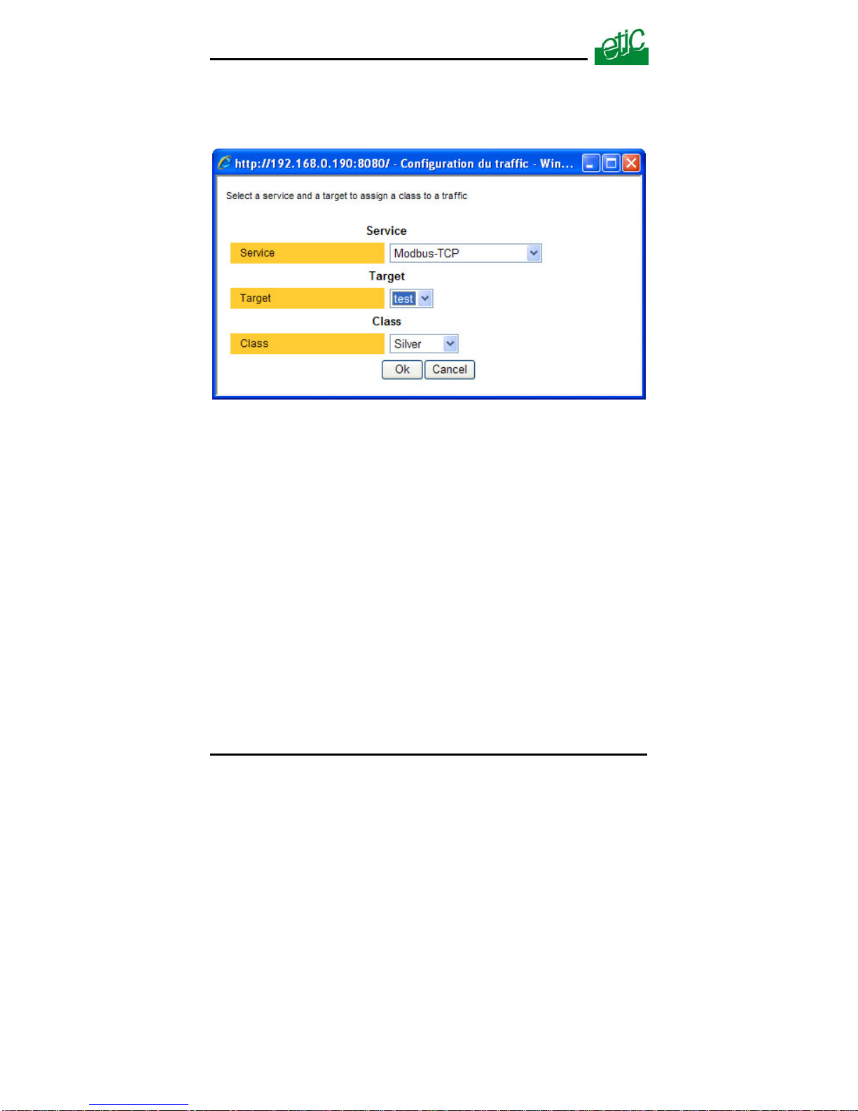
Step 5 : Classify the traffics
• Select the QoS menu and then the “Traffic classification” menu.
• Click the “Add a traffic” button. The traffic window is displayed.
• Select a service (modbus TCP or html or FTP …), a target and a class
and click OK.
Page 42 User’s guide ref 9014709-02 XSLAN SHDSL switch
Page 43

HTML SET UP & DIAGNOSTIC
XSLAN SHDSL switch User’s guide ref 9014709-02 Page 43
15 SNMP set up
The XSLAN is compliant with the MIB2.
The SNMP manager can acquire the status (Connected or not connected)
of each SHDSL port.
The XSLAN is also able to send SNMP traps
when each SHDSL connection is established.
or when each SHDSL connection is disconnected.
To enable the SNMP traps function,
• Select the “Alarm” menu and then the “SNMP” menu :
• Select the “Activation” checkbox.
• Enter the IP address of the management system.
• Enter the Sysname value (for instance XSLAN).
• Enter the Syslocation value (for instance the label of the site where
the XSLAN is installed).
• Enable the traps related to the different events :
Product startup
SHDSL connection
SHDSL disconnection
Page 44
HTML SET UP & DIAGNOSTIC
Page 44 User’s guide ref 9014709-02 XSLAN SHDSL switch
16 Serial gateway set up
The XSLAN-1220 or 2220 features 1 RS232 and 1 RS485 – 2 wires –
ports.
The XSLAN-1230 or -2230 features two RS232 serial ports.
A serial gateway can be assigned to each serial port .
However, if the same type of gateway is assigned to both serial ports, the
UDP or TCP port numbers must be different.
For instance, it is not possible to use modbus TCP with the port 502 at the
same time on the serial ports 1 and 2.
The gateways listed below are provided :
Modbus client or server (i.e. master or slave)
To connect several serial modbus slaves to several IP modbus clients.
Or to connect a serial modbus master to an IP modbus server.
RAW TCP server or client :
To connect 2 serial devices through an IP network.
RAW UDP :
To exchange serial data between several serial and IP devices, through
an IP network, using a table of IP addresses..
Telnet :
To connect a Telnet terminal to the RAS.
Unitelway slave :
To connect a serial unitelway master to an IP network.
Page 45

HTML SET UP & DIAGNOSTIC
XSLAN SHDSL switch User’s guide ref 9014709-02 Page 45
16.1 Modbus gateway
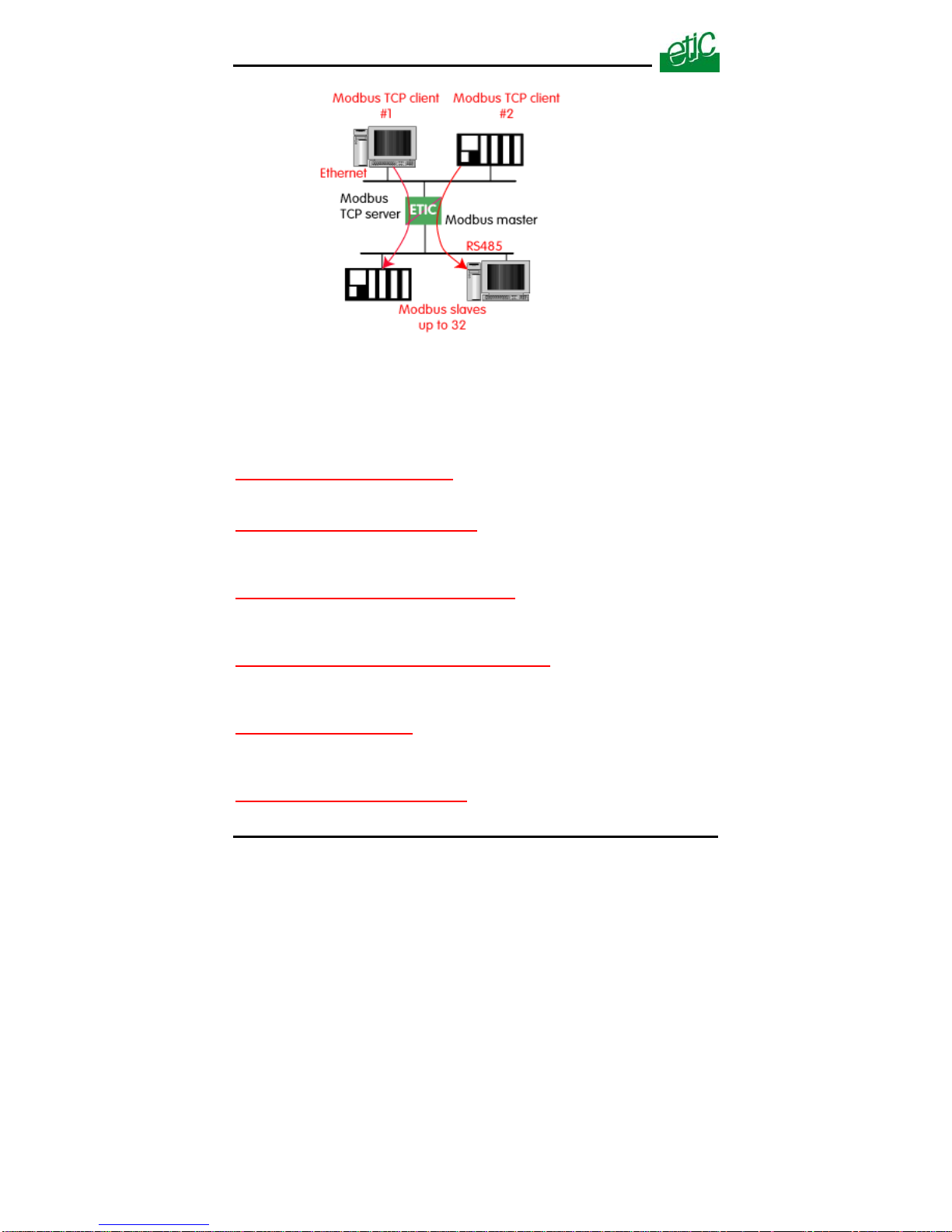
The ETIC modbus gateway is made to link modbus devices connected to
its serial interface to TCP modbus devices connected to the ethernet
TCP/IP network.
A TCP Modbus client device is a device connected to the ethernet
TCP/IP network and able to send a modbus request to a modbus TCP
server which is in charge of answering; A TCP modbus client is equivalent
to a master.
A TCP Modbus server device is a device connected to the ethernet
TCP/IP network and able to answer to a modbus request received from a
TCP modbus client device. A TCP modbus server is equivalent to a slave.
A TCP modbus server can answer to any client of the Ethernet TCP/IP
network.
The ETIC modbus gateway can be configured
either
to link serial slaves to several TCP modbus clients devices connected to
the ethernet network; in that case, select the modbus client gateway,
or
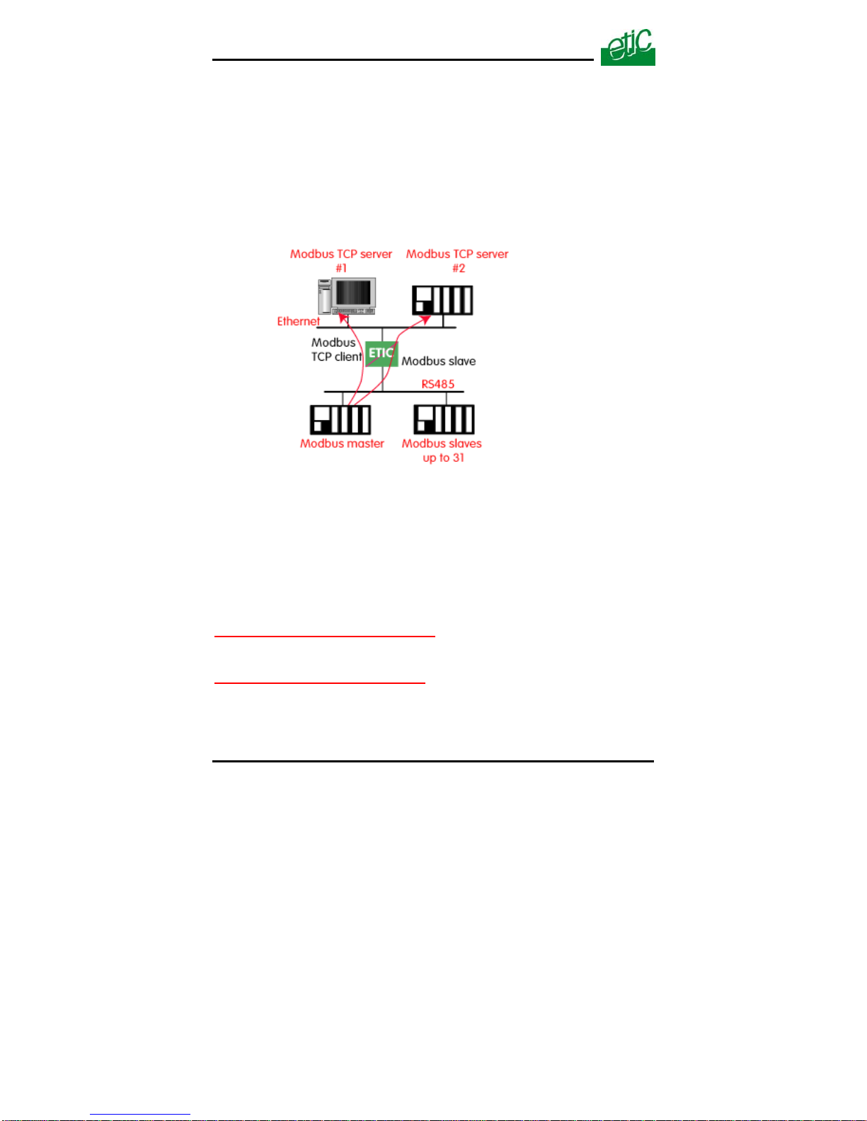
to connect a serial master to several TCP modbus servers devices
connected to the ethernet network; in that case, select the modbus server
gateway.
16.1.1 Modbus server gateway
Modbus slaves devices are connected to the serial interface.
That gateway links asynchronous modbus slaves to modbus TCP clients
connected to the ethernet network.
Each TCP client (i.e. modbus master) can send requests to any modbus
slave device of the serial interface.
Page 46
HTML SET UP & DIAGNOSTIC
To configure the Modbus server gateway,
• select the modbus menu and then modbus server,
• enable the modbus server gateway and set the parameters as follows:
“Modbus protocol” parameter :
Select the RTU or ASCII option
“Activate Proxi cache” parameter :
Enable the proxi option if you wish to avoid to frequent requests on the
serial interface.
“Cache refreshment period” parameter :
the same request is received twice or more inside that delay, it will be
sent only once to the slave on the serial interface.
“Timeout waiting for the answer” parameter :
Set up the timeout the gateway has to wait for the answer of the modbus
slave.
“Local retry” parameter :
Set up the number of times the gateway will repeat a request to one of the
modbus slaves on the serial interface before declaring a failure.
“Inter-character gap” parameter :
Set up the maximum delay the gateway will have to wait between a
Page 46 User’s guide ref 9014709-02 XSLAN SHDSL switch
Page 47

HTML SET UP & DIAGNOSTIC
XSLAN SHDSL switch User’s guide ref 9014709-02 Page 47
received character of a modbus answer frame on the serial interface and
the following character of the same frame.
“Modbus slave address* parameter :
If only one modbus slave device is connected to the serial interface,
set the modbus address of the device; any TCP modbus request
received by the gateway will be sent on the serial interface using that
modbus address.
If several modbus slave devices are connected to the serial
interface, select “specified by modbus TCP client”;
In that case, each request sent by the TCP/IP modbus client to one of
the slaves connected to the serial interface must specify the modbus
slave address value in the modbus address field.
“TCP inactivity Timeout” parameter :
Set the time the gateway will wait before disconnecting the TCP link if no
characters are received.
“TCP port number” parameter :
Set the port number the gateway has to use.
Page 48
HTML SET UP & DIAGNOSTIC
16.1.2 “Modbus client” gateway
That gateway can be used only if a serial modbus master device is
connected to the serial interface of the XSLAN.
That modbus master can send requests to slaves connected to the serial
interface or to up to 256 modbus TCP servers connected to the IP
network (i.e. modbus slaves).
To configure the modbus client gateway,
• select the modbus menu and then “modbus client” menu;
• enable the “modbus client” gateway and set up the parameters as
follows :
“ASCII / RTU protocol” parameter :
Select the right option
“Inter-character gap” parameter :
Set up the maximum delay the gateway will have to wait between a
received character of a modbus answer frame and the following character
of the same frame.
Page 48 User’s guide ref 9014709-02 XSLAN SHDSL switch
Page 49

HTML SET UP & DIAGNOSTIC
XSLAN SHDSL switch User’s guide ref 9014709-02 Page 49
“TCP inactivity Timeout” parameter :
Set the time the gateway will wait before disconnecting the TCP link if no
characters are detected.
“TCP port number” parameter :
Set the TCP port number the gateway has to use.
“IP address table” :
When the serial master sends a modbus request to a slave, it includes the
modbus address of that slave.
If that slave is not a serial slave but a TCP modbus server on the ethernet
network, the ETIC gateway needs to know what is its IP address.
That IP address table allows to assign an IP address to each modbus
slave address.
• To assign an IP address to each modbus slave device with which the
serial master device needs to communicate, click the “add a link”
button; Assign an IP address in front of each modbus slave address
with which the serial master device will have to communicate.
.
Page 50
HTML SET UP & DIAGNOSTIC
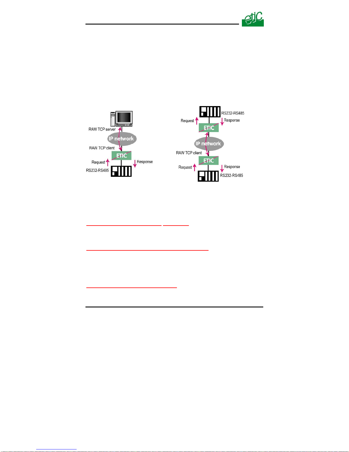
16.2 RAW TCP gateway
16.2.1 Raw client gateway
The RAW client gateway can be used if a serial “master” device has to
send requests to one slave device (also called server) located on the IP
network.
The server can be either an ETIC gateway or a PC including a software
TCP server.
• Select the “transparent” and then the “raw client COM1” or the “raw
client COM2” menu .
• Enable the raw client gateway; and set up the parameters as follows :
“RS232/485 input buffer size”
parameter :
Set up the maximum length of an asynchronous string the gateway will
store before transmitting it to the IP network.
“Timeout of RS232/485 end of frame” parameter
:
Set up the delay the gateway will wait before declaring complete a string
received from the asynchronous device.
Once declared complete, the gateway will transmit the string to the IP
network.
“TCP inactivity Timeout” parameter
:
Set the time the gateway will wait before disconnecting the TCP link if no
characters are detected.
Page 50 User’s guide ref 9014709-02 XSLAN SHDSL switch
Page 51
HTML SET UP & DIAGNOSTIC
“TCP port number” parameter :
Set the port number the gateway has to use.
If the Raw TCP client gateway is assigned to both serial COM ports, the
CP port numbers must be different on each port. T
“Raw server IP address” parameter
:
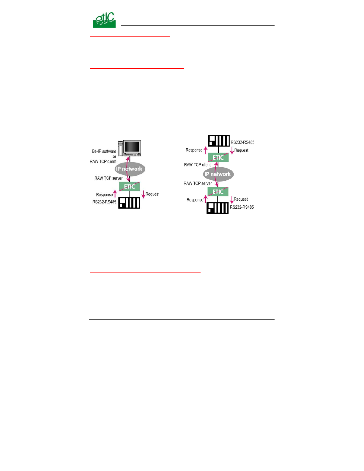
The raw client gateway is able to communicate with a raw server
gateway.
Assign an IP address to define the destination gateway.
nswer requests
oming from devices located on the IP network and acting like a master
16.2.2 Raw server gateway
That gateway can be used if a serial slave device has to a
c
(also called TCP client).
• Select the “transparent” and then the “raw server COM1” or the
“raw server COM2” menu.
Enable the raw server gateway and set up the parameters as
lows
“RS232/485 input buffer size” parameter :
•
fol :
t up t
re transmitting it to the IP network.
eter :
Se he maximum length of an asynchronous string the gateway will
store befo
XSLAN SHDSL switch User’s guide ref 9014709-02
Page 51
“Timeout of RS232/485 end of frame” param
Set up the delay the gateway will wait before declaring complete a string
received from the asynchronous device.
Page 52

HTML SET UP & DIAGNOSTIC
Page 52 User’s guide ref 9014709-02 XSLAN SHDSL switch
string to the IP Once declared complete, the gateway will transmit the
network.
“TCP inactivity Timeout” parameter :
Set up the time the gateway will wait before disconnecting the TCP link if
o characters are detected. n
“TCP port number” parameters :
Set up the port number the gateway has to use.
the Raw TCP server gateway is assigned to both serial COM ports, the
on each port.
If
TCP port numbers must be different
Page 53
HTML SET UP & DIAGNOSTIC
16.3 RAW UDP gateway
16.3.1 Overview
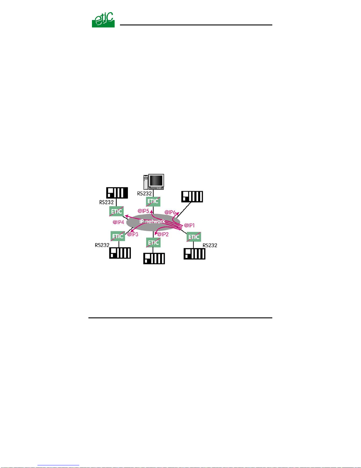
The RAW UDP gateway enables you to connect together a group of
serial or IP devices through an IP network.
The group can include IP devices if they have the software pieces able to
receive or transmit serial data inside UDP.
Serial data transmitted by each device is transmitted to all other serial
devices through the IP network.
A table of IP destination gateways is stored in each IPL-E belonging to the
group.
The serial data is encapsulated in the UDP protocol.
The UDP frame is sent to each destination IP address stored in the table.
16.3.2 Configuration
• Select the “gateway” menu and then the “Transparent” menu and then
click “RAW UDP”.
XSLAN SHDSL switch User’s guide ref 9014709-02
Page 53
Page 54

HTML SET UP & DIAGNOSTIC
Page 54 User’s guide ref 9014709-02 XSLAN SHDSL switch
• Select the “Activate” option.
« Serial input buffer size” parameter (value 1 to 1024)
:
Sets the maximum size of an UDP frame.
“End of frame time-out” parameter (value 10 ms to 5 sec ) :
Sets the delay the gateway will wait before sending the UDP frame
towards the IP network when no characters are received from the serial
interface.
«UDP port number» parameter :
Sets the UDP port number.
If the Raw UDP gateway is assigned to both serial COM ports, the UDP
port numbers must be different on each port.
“IP addresses of the destination devices » table :
This table stores the IP addresses of the gateways to which the serial data,
encapsulated inside UDP, have to be sent.
A different UDP port number can be entered for each destination IP address.
Page 55
HTML SET UP & DIAGNOSTIC
16.4 Multicast gateway
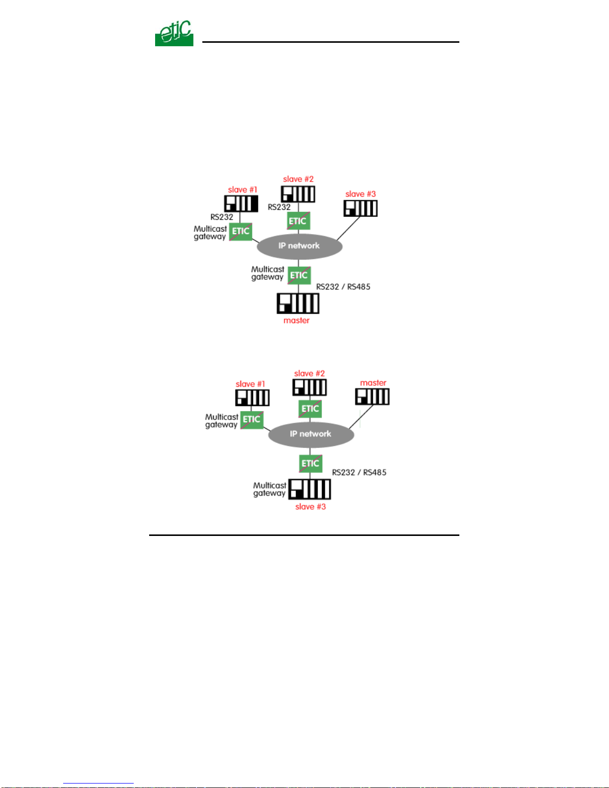
Internet Protocol multicast is a bandwidth-conserving technology that
reduces traffic by simultaneously delivering a single stream of information
to thousands of corporate recipients.
Thus, the multicast gateway must be used when
• a serial master device has to send requests to multiple slave devices;
that devices can be IP or serial devices.
• Or when an IP master device (client) has to send requests to multiple
slave devices; that devices can be IP or serial devices.
XSLAN SHDSL switch User’s guide ref 9014709-02
Page 55
Page 56

HTML SET UP & DIAGNOSTIC
Page 56 User’s guide ref 9014709-02 XSLAN SHDSL switch
The Internet Assigned Numbers Authority (IANA) controls the assignment
of IP multicast addresses.
The range of addresses from 224.0.1.0 through 238.255.255.255 are
called “globally scoped addresses”. They can be used to multicast data
between organizations and across the Internet.
The range of addresses from 239.0.0.0 through 239.255.255.255 contains
limited scope addresses or administratively scoped addresses. These are
defined by RFC 2365 to be constrained to a local group or organization.
Routers are typically configured with filters to prevent multicast traffic in
this address range from flowing outside an autonomous system (AS) or
any user-defined domain. Within an autonomous system or domain, the
limited scope address range can be further subdivided so those local
multicast boundaries can be defined. This also allows for address reuse
among these smaller domains.
Note This address range is only for the group address or destination
address of IP multicast traffic. The source address for multicast
datagrams is always the unicast source address.
To configure the multicast gateway,
• Select the “transparent” and then the “multicast” menus.
• Enable the multicast gateway and set up the parameters as follows :
“RS232/485 input buffer size” parameter
Set up the maximum length of an asynchronous string the gateway will
store before transmitting it to the IP network.
“Timeout of RS232/485 end of frame” parameter
Set up the delay the gateway will wait before declaring complete a string
received from the asynchronous device.
Once declared complete, the gateway will transmit the string to the IP
network.
“TCP port” parameter
Set the port number the gateway has to use.
Multicast group IP address
Enter the multicast IP address assigned to the group with respect to the rules of
the IANA authority.
Page 57

HTML SET UP & DIAGNOSTIC
XSLAN SHDSL switch User’s guide ref 9014709-02 Page 57
16.5 Unitelway gateway
The unitelway gateway is made to connect an RS232-RS485 unitelway
master PLC to an IP network.
• Select the Unitelway menu; select "enable the unitelway transceiver".
• Enter the XWAY address assigned to the asynchronous unitelway
PLC on the IP network.
• Select « enable the IP-RS transceiver ».
• Enter the Xway address of the master PLC and, if they exist, the
Xway addresses of the slave unitelway PLCs connected to the master
PLC.
Page 58

HTML SET UP & DIAGNOSTIC
Page 58 User’s guide ref 9014709-02 XSLAN SHDSL switch
17 Diagnostic menu
• Logs :
The log displays the last 300 dated events : ethernet & shdsl connections
and disconnections, power on, RS232 gateway events.
• Network status :
That page displays detailed information about each interface of the
XSLAN (SHDSL 1 & 2, ethernet, RS232-RS485).
The SHDSL alinea shows the status of each shdsl interface :
Data rate
Connection status : Connected / connection in progress / disconnected)
Quality level of the connection from 1 to 5 : The quality level has to be at least 3.
The Show statistics button displays a page providing detailed technical
information about each shdsl link quality.
• DIP-switches status :
That screen displays the status of the DIP-switches located on the top of
the product.
• Ping :
That screen enables to send a ping frame to an IP address.
IO control
That screen displays the status of the digital input and output and allows
to set ON or OFF the alarm digital output.
.
Page 59
APPENDIX
DATA RATE VERSUS DISTANCE
XSLAN SHDSL switch User’s guide ref 9014709-02
Page 59
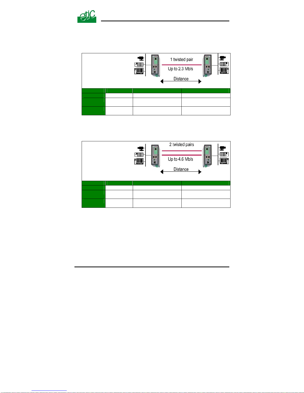
Maximum distance
between 2 switches
versus da
ta rate
• 1 twisted pair (2 wires)
Data rate► 128 Kb/s 1.15 Mb/s 2.3 Mb/s
▼Wire Φ
0.9 mm
13 Km (8
miles)
8 Km (5 miles) 6 Km (3.7 miles)
0.4 mm
7 Km (4.3
miles)
4 Km (2.5 miles) 3.5 Km (2.1 miles)
Maximum distance versus
data rate
• 2 twisted pair (4 wires)
• Inverse-multiplexing
Data rate► 256 Kb/s 2.3 Mb/s 4.6 Mb/s
▼Wire Φ
0.9 mm
13 Km (8
miles)
8 Km (5 miles) 6 Km (3.7 miles)
0.4 mm
7 Km (4.3
miles)
4 Km (2.5 miles) 3.5 Km (2.1 miles)
Page 60

Page 61

APPENDIX 2
HTML server
XSLAN SHDSL switch User’s guide ref 9014709-02
Page 61
System
Administration To protect access to the administration server.
Target To define the machines connected to the LAN ( for QoS only)
Service list To define the port (TCP or others) used between the
machines
Date & time To set date and time of the day
Syslog To export the Log to a PC
Firmware update Update the product firmware
Save / restore To download / upload the configuration file of the product.
Reboot To restart the product
Ethernet & switching
SHDSL port To set the data rate over shdsl
Ethernet port To tune the Ethernet ports
VLAN To enable VLANs per port
IP protocol & routes
IP protocol To enter the IP @ of the unit
RIP To enable the RIP protocol
Static routes To enable IP routing and set the routes
Quality of service
Activate To enable the function
Traffic classification to assign a priority class to each TCP port and IP source @
Classes To set the minimum bandwidth allocated to each class
Page 62

APPENDIX 2
HTML server
Page 62 User’s guide ref 9014709-02 XSLAN SHDSL switch
Alarms To set the alarms
SNMP To define traps and SNMP server
IO To defines the conditions the output will open
Email To enter the alarm email parameters
IP to RS gateway (XSLAN-1220, 1230, 2220 & 2230)
Modbus To configure the modbus gateway.
Transparent To configure the raw, multicast & telnet gateway
Unitelway To configure the unitelway gateway
Diagnostics
Logs To display logs
Network status To display all the parameters of the connection in use
MAC & IP @,
SHDSL connection : data rate, error rate, statistics
Gateway status To display the status of the gateway
Microswitch To display the micro switches current position
Ping To ping a machine
Table of routes To display the table of routes
Ping To ping a machine
IO control To display the IOs status
About
To display the firmware and hardware identification
Page 63

APPENDIX 2
HTML server
XSLAN SHDSL switch User’s guide ref 9014709-02 Page 63
Page 64

13, Chemin du Vieux Chêne
38240 Meylan France
Tel : 33 4 76 04 20 00
Fax : 33 4 76 04 20 01
E-mail : [email protected]
Web : www.etictelecom.com
 Loading...