

ETIC 1400, 1230, 2400, 2220, 2230 User Manual
...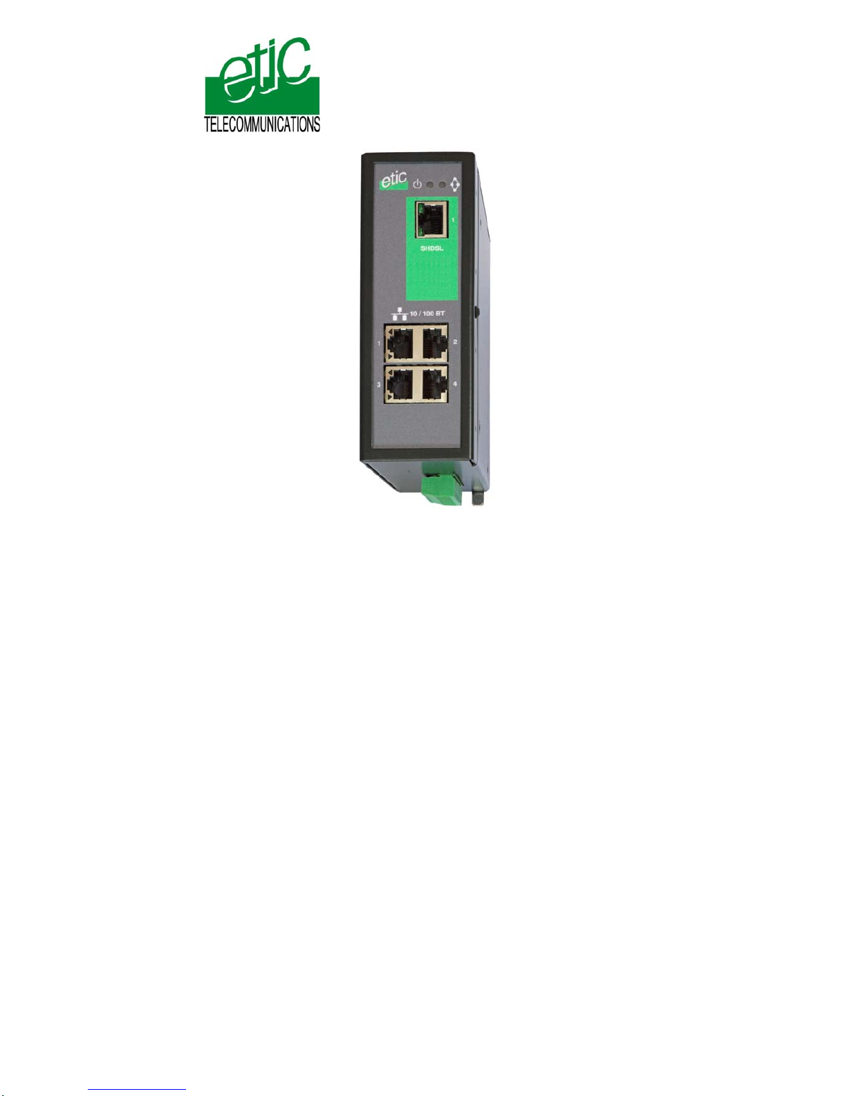
XSLAN
SHDSL switch
_________________
User’s guide
Document reference : 9014709-02
_________________

The XSLAN SHDSL switch is manufactured by
ETIC TELECOM
13 Chemin du vieux chêne
38240 MEYLAN
FRANCE
TEL : + 33 4-76-04-20-00
FAX : + 33 4-76-04-20-01
e-mail : contact@etictelecom.com
web : www.etictelecom.com
Hotline
TEL : + 33 4-76-04-20-05
FAX : + 33 4-76-04-20-01
e-mail : hotline@etictelecom.com

CONTENT
XSLAN SHDSL switch User’s guide ref 9014709-02 Page 3
OVERVIEW
1
PRODUCTS IDENTIFICATION...........................................................................6
2 PRODUCT OVERVIEW.......................................................................................7
2.1 Function..................................................................................................7
2.2 Data rate versus distance.....................................................................7
2.3 Ethernet ports........................................................................................8
2.4 VLAN.......................................................................................................8
2.5 Quality of service...................................................................................8
2.6 Serial gateway........................................................................................8
2.7 Diagnostic functions.............................................................................8
2.8 Html or DIP switches configuration....................................................8
3
DATA-SHEET......................................................................................................9
INSTALLATION
1
PRODUCT DESCRIPTION...............................................................................11
1.1 Leds.......................................................................................................12
1.2 Connectors...........................................................................................13
1.3 DIP switches and push-button...........................................................15
2 VENTILATION...................................................................................................16
3 SUPPLY VOLTAGE..........................................................................................16
4 FUSE.................................................................................................................16
5 ETHERNET PORTS..........................................................................................16
6 RS232 (XSLAN—1220, 1230, 2220 AND -2230) .............................................17
7 RS485 (XSLAN-1230 OR -2230)......................................................................17
8 SHDSL LINE.....................................................................................................18
9 INPUT AND OUTPUT.......................................................................................20
../..

CONTENT
Page 4 User’s guide ref 9014709-02 XSLAN SHDSL switch
DIP SWITCHES CONFIGURATION
1 OVERVIEW.......................................................................................................21
2 ONE TWISTED PAIR SHDSL LINE SET UP....................................................21
3 TWO TWISTED PAIRS SHDSL LINE SET UP.................................................23
4 TESTING THE SHDSL CONNECTION AND ADJUSTING THE DATA RATE24
HTML CONFIGURATION
1
SET UP STEPS.................................................................................................25
2 ENABLING HTML CONFIGURATION .............................................................26
3 CONNECTING A PC TO THE XSLAN FOR CONFIGURATION.....................26
3.1 Overview...............................................................................................26
3.2 First configuration...............................................................................27
3.3 Modifying the configuration from the LAN........................................28
4 REBOOTING THE XSLAN AFTER PARAMETERS CHANGES.....................28
5 RECOVERING THE FACTORY LAN IP ADDRESS ........................................28
6 RECOVERING THE FACTORY CONFIGURATION.......................................29
7 RESTRICTING ACCESS TO THE ADMINISTRATION SERVER....................29
8 RECOVERING A FREE ACCESS TO THE ADMINISTRATION SERVER......29
9 ASSIGNING AN IP ADDRESS TO THE LAN INTERFACE.............................30
10 IP ROUTING AND BROADCAST FILTERING................................................30
11 ONE TWISTED PAIR SHDSL CONNECTION SET UP....................................33
11.1 Set up....................................................................................................33
11.2 Testing the SHDSL connection and adjusting the data rate...........34
12 TWO WISTED PAIRS UP SHDSL CONNECTION SET UP.............................35
12.1 SHDSL port set up...............................................................................35
12.2 Testing the SHDSL connection and adjusting the data rate...........36
../..

CONTENT
XSLAN SHDSL switch User’s guide ref 9014709-02 Page 5
… HTML CONFIGURATION
13
VLAN SET UP...................................................................................................37
13.1 Overview...............................................................................................37
13.2 VLAN set up .........................................................................................39
14 QUALITY OF SERVICE (QOS) SET UP..........................................................40
14.1 DiffServ benefits & overview..............................................................40
14.2 QoS set up............................................................................................41
15 SNMP SET UP..................................................................................................43
16 SERIAL GATEWAY SET UP............................................................................44
16.1 Modbus gateway..................................................................................45
16.2 RAW TCP gateway...............................................................................50
16.3 RAW UDP gateway ..............................................................................53
16.4 Multicast gateway................................................................................55
16.5 Unitelway gateway...............................................................................57
17 DIAGNOSTIC MENU ........................................................................................58
Appendix 1 : Data rate versus distance and cable quality
Appendix 2 : Html server description

INSTALLATION
Switch Shdsl XSLAN Notice d’utilisation ref 9014309-01 page 6
1 Products identification
XSLAN SHDSL switch
1400 1220 1230 2400 2220 2230
SHDSL ports
1 1 1 2 2 2
Maximum data rate (Mb/s)
2.3 2.3 2.3 4.6 4.6 4.6
10-100 Mb/s Ethernet ports
4 2 2 4 2 2
RS232
0 1 2 0 1 2
RS485
0 1 0 0 1 0
Basic IP routing feature
Yes Yes Yes Yes Yes Yes
VLAN
Yes Yes Yes Yes Yes Yes
Quality of service
Yes Yes Yes Yes Yes Yes
Gateway
(Raw, telnet, modbus,
unitelway)
0 2 2 0 2 2
Line cable *
1 1 1 2 2 2
Χ The product is delivered with Cable ref. CAB614 for
connection to the line (Qty 1 or 2)
INSTALLATION
2 Product overview
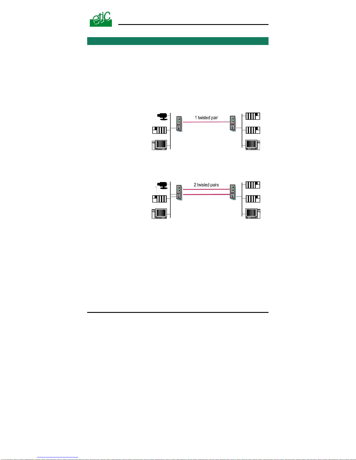
2.1 Function
The XSLAN shdsl switch enables to extend an Ethernet network over
kilometers using one or two simple voice-grade twisted pairs (telephone
lines).
The XSLAN-1400 or 1220 or 1230 come with one SHDSL interface; they
can be connected to a one twisted pair line.
They feature up to 2.3 Mb/s.
One pair operation
up to 2.3 Mb/s
XSLAN-1400
XSLAN-1220
XSLAN-1230
The XSLAN-2400 or 2220 or 2230 come with two SHDSL interfaces; they
can be connected to a two twisted pair line.
They feature up to 2.3 Mb/s.
Two pairs operation
up to 4.6 Mb/s
XSLAN-2400
XSLAN-2220
XSLAN-2230
2.2 Data rate versus distance
Each interface features an adaptive data rate from 128 Kb/s up to 2.3
Mb/s.
The data rate is a function of the cable quality and the distance with the
next SHDSL switch. For instance, the maximum distance between 2
switches through a line is 13 Km (8 miles) with a 0.9 mm wire diameter
cable.
The table in appendix 1 gives the data rate which can be expected over a
line versus the length of the line.
XSLAN SHDSL switch User’s guide ref 9014709-02
Page 7

INSTALLATION
Page 8 User’s guide ref 9014709-02 XSLAN SHDSL switch
2.3 Ethernet ports
The XSLAN provides 2 or 4 Ethernet RJ45 interfaces (depending on the
product reference).
2.4 VLANs
The XSLAN features VLAN per port :
Each Ethernet port can be assigned to a particular VLAN. A device
connected to an Ethernet port belonging to a particular VLAN can
communicate only with devices connected to Ethernet ports belonging to
the same one.
2.5 Quality of service
The product provides “DiffServ” quality of service functionality to give
transmission priority to critical applications.
Devices TCP ports and IP addresses are classified in 4 priority classes.
A minimum and a maximum bandwidth is allocated to each class.
2.6 Serial gateway
The XSLAN –1220, -1230, -2220 or –2230 feature a 2 ports serial
gateway.
The gateway features raw TCP client and server, raw UDP, modbus
client and server, telnet and multicast.
2.7 Diagnostic functions
The XSLAN html server provides diagnostic pages giving the guarantee
the transmission quality is what it has to be.
2.8 Html or DIP switches configuration
The XSLAN can be configured either with an html browser if advanced
functions are necessary (QoS, RS gateway, diagnostic …).
It can be configured with a few DIP switches for simple unmanaged
applications.
INSTALLATION
XSLAN SHDSL switch User’s guide ref 9014709-02 Page 9
3 Data-sheet
Dimensions 137 x 48 x 116 mm (h, l, d)
C.E.M EN50082-2
Electrical safety EN 60950
Lightning EN61000-4 et –5
Supply voltage XSLAN-1400 or –2400 or –1230 or –2230 : 9 to 60 VDC
XSLAN-1220 –2220 : 9 to 30 VDC
Consumption 4W
Operating T° -20°/ + 60°C non condensing
SHDSL ITU-T G.991.2, 802.3ah : 2BaseTL (EFM)
Data rate : 128 kb/s to 2.3 Mb/s with 2 wires
Latency : 4 ms
Ethernet 10/100 Mb/s Half / Full duplex Auto MDI/MDIX
Switch Store and forward – 1024 MAC @
IP Routing Static routes
RIP V2
QoS DiffServ compliant with RFC 2474, 2475, 2597, 2598
4 priority levels (premium, gold, silver, bronze)
SNMP SNMP V2 – MIBII and traps
VLAN Per port
RS232-RS485 1200 to 115200 kb/s parity E/O/N
Raw TCP client and server
Raw UDP
Multicast
Modbus client and server
Unitelway
Telnet
Logs 300 events (date & time)
Configuration Managed mode : HTML browser
Unmanaged mode : DIP switches

INSTALLATION
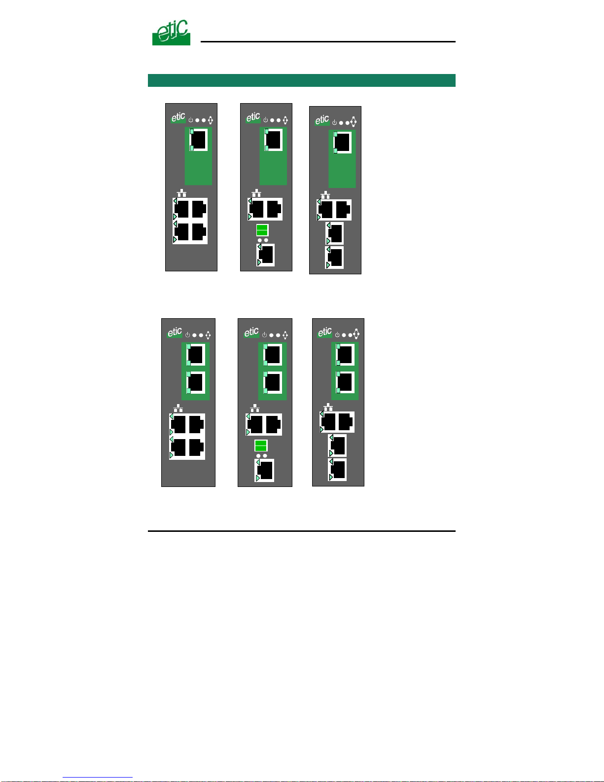
1 Product description
10 / 100 BT
1
2
SHDSL
1
3
4
1
10 / 100 BT
1
2
RS485
RS232
Rx Tx
SHDSL
1
1
10 / 100 BT
1
2
RS232
SHDSL
1
2
RS232
1
XSLAN-1400 XSLAN-1220 XSLAN-1230
10 / 100 BT
1
2
SHDSL
1
3
4
2
10 / 100 BT
1
2
RS485
RS232
Rx Tx
SHDSL
1
1
1
10 / 100 BT
1
2
RS232
SHDSL
1
2
2
RS232
1
XSLAN-2400 XSLAN-2220 XSLAN-2230
Switch Shdsl XSLAN Notice d’utilisation ref 9014309-01
page 11
INSTALLATION
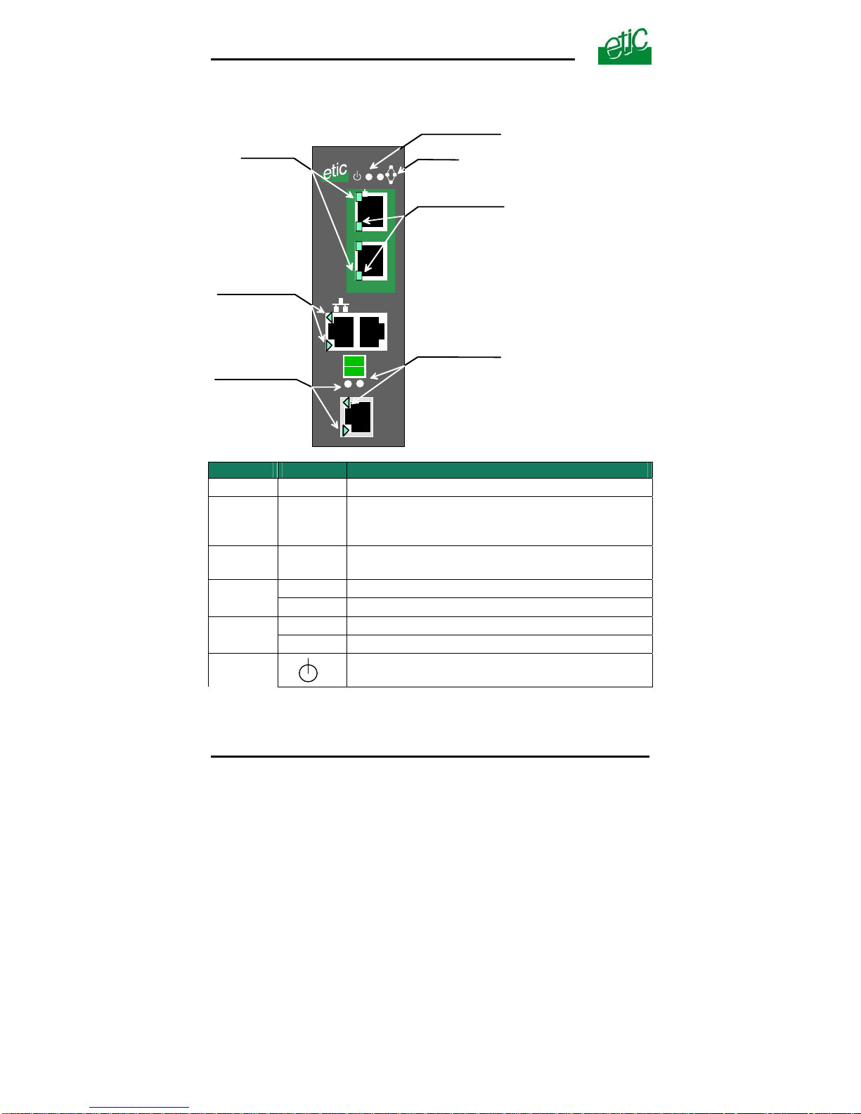
1.1 Leds
10 / 10 0 BT
1
2
RS232
SHDSL
1
2
RS485
Not used
OPERATIO N le d
Ethernet activity led
port 1 & port 2
SHDSL Errors
port 1 & port 2
RX led
(to the XSLAN)
TX led
(from the XSLAN)
RS485
Rx
Tx
SHDSL connection
leds
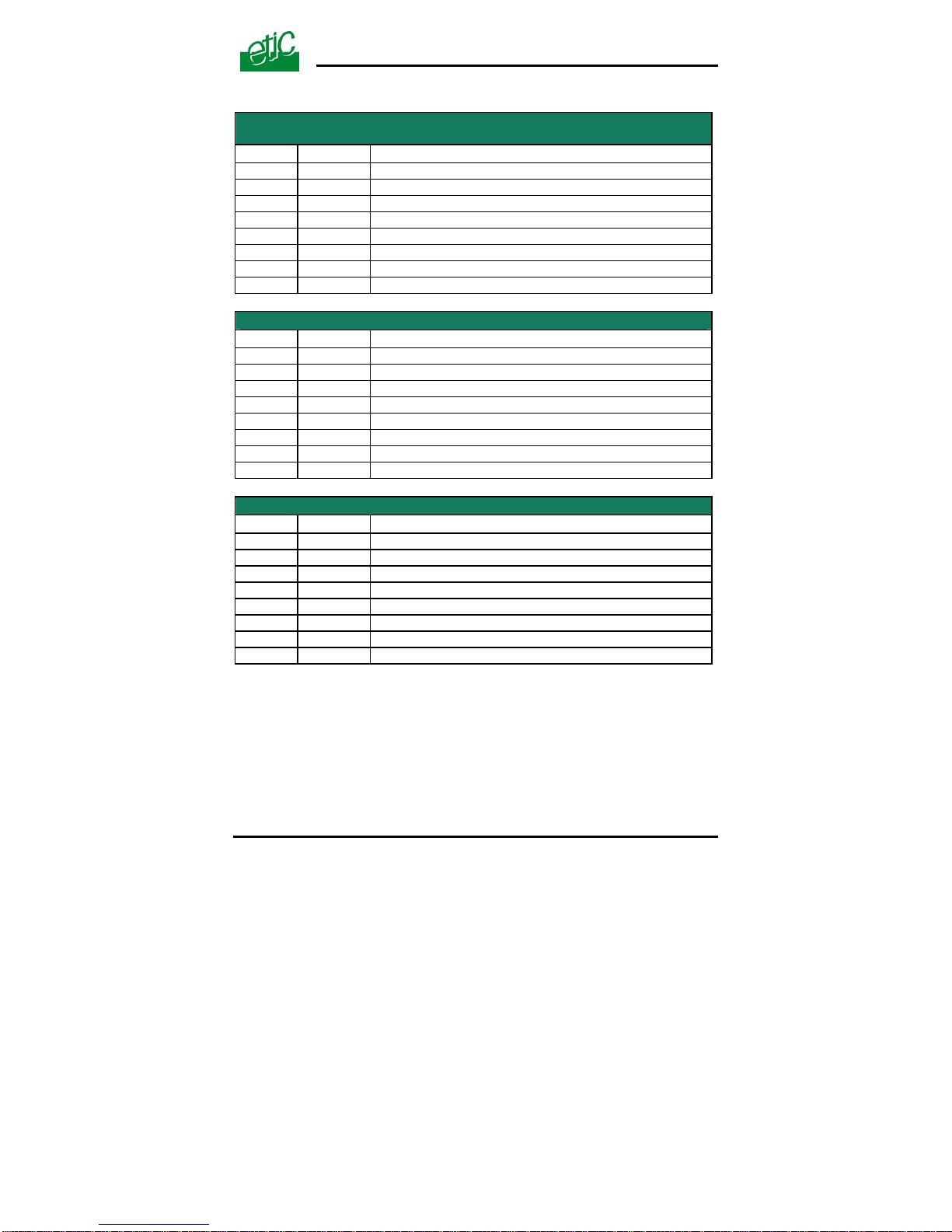
Function Led Description
Ethernet
LINK/DATA
Ethernet activity
Shdsl led
(Lower)
Slowly blinking : Shdsl connection in process
Lit on : Shdsl connection set
Quickly blinking : Traffic over the SHDSL link
Line
Shdsl led
(Upper)
Error
Off : Error-free transmission
Quickly blinking : Transmission errors
RS232
Rx
Bytes received from the RS232 (to XSLAN)
Tx
Bytes transmitted to the RS232 (from XSLAN)
RS485
Rx
Bytes received from the RS485 (to XSLAN)
Tx
Bytes transmitted to the RS485 (from XSLAN)
Operation
Green : Ready for use
Red : Alarm
Page 12 User’s guide ref 9014709-02 XSLAN SHDSL switch
INSTALLATION
XSLAN SHDSL switch User’s guide ref 9014709-02 Page 13
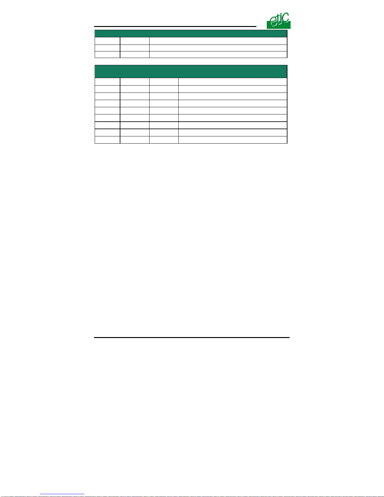
1.2 Connectors
8 pins screw block
Supply voltage and input / output
Pin Nr Signal Function
1 Power 1 + Supply voltage input 1
2 Power 1 - 0 V
3 Power 2 + Supply voltage input 2
4 Power 2 - 0 V
5 3V3 + 3.3 VDC voltage provided by the product
6 In Input
7 F + Output + (max 48Vdc - 0,5A)
8 F - Output -
SHDSL RJ45 connector
Pin Nr Signal Function
1 N.C. 2 N.C. 3 N.C. 4 TIP SHDSL line
5 RING SHDSL line
6 N.C. -
7 N.C. 8 N.C. -
Ethernet RJ45 connector
Pin Nr Signal Function
1 Tx + TX polarity +
2 Tx - TX polarity 3 Rx + Reception polarity +
4 N.C 5 N.C 6 Rx - Reception polarity 7 N.C. 8 N.C. -
INSTALLATION
Page 14 User’s guide ref 9014709-02 XSLAN SHDSL switch
RS485 2 pins screw block
Pin Nr Signal Function
1 A RS485 polarity A
2 B RS485 polarity B
RS232 RJ45 connector
(To connect to a DCE)
Pin Nr Circuit Function
1 DTR - 108 Out
Data terminal ready
2 TD - 103 Out
Data Emission
3 RD - 104 IN
Data Reception
4 DSR - 107 IN
Data set ready
5 SG - 102 -
Ground
6 Not used Out
-
7 CTS - 106 IN
Clear to send
8 RTS - 105 Out
Request to send
INSTALLATION
XSLAN SHDSL switch User’s guide ref 9014709-02 Page 15
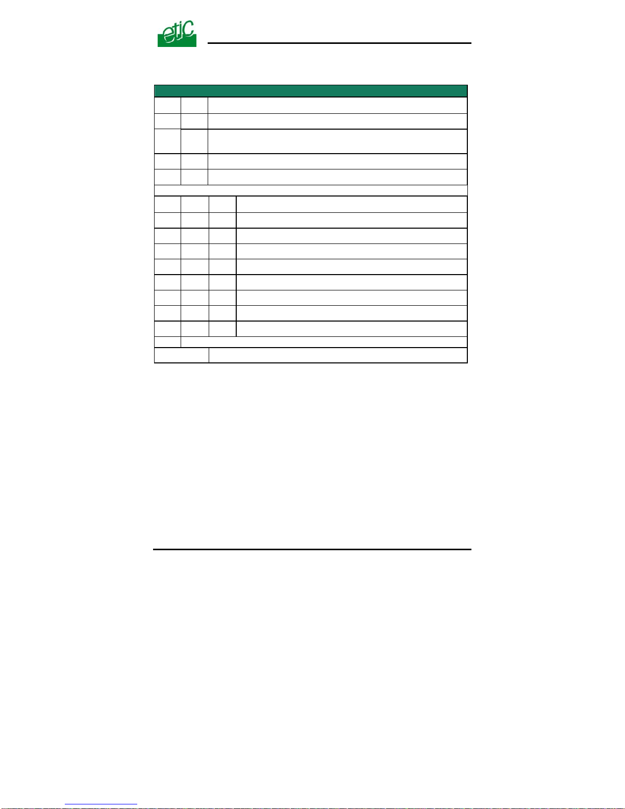
1.3 DIP switches and push-button
DIP switches
SW 1 SW 2
Management
OFF OFF
The current IP@ of the product is the stored IP @
ON OFF
The active IP@ of the product is the factory IP@ : 192.168.0.128
No login and password are required to access to the html server
OFF ON
The active IP@ is provided by the BOOTP or DHCP server
ON ON
No IP @ is assigned to the product; DIP switch configuration
SW 3 SW 4 SW 5
Shdsl port 1
OFF OFF OFF
NTU mode
OFF OFF ON
LTU mode - Auto
OFF ON OFF
LTU mode – 2304 kbit/s
OFF ON ON
LTU Mode – 2048 kbit/s
ON OFF OFF
LTU Mode – 1536 kbit/s
ON OFF ON
LTU Mode – 1024 kbit/s
ON ON OFF
LTU Mode – 512 kbit/s
ON ON ON
LTU Mode – 256 kbit/s
SW 6 to SW 12
Not used - Must be left OFF
Push-button :
A push-button is located close to the DIP switches.
It enables to restore the factory profile.
To restore the factory profile, switch the power on while pressing the
push-button until the OPERATION led turns green.
Attention : Once the factory profile has been restored, the stored
configuration is lost.

INSTALLATION
Page 16 User’s guide ref 9014709-02 XSLAN SHDSL switch
2 Ventilation
To avoid overheating when the ambient temperature is high, leave a 1 cm
(0.5 inch) space on each side of the product.
3 Supply voltage
The product comes with 2 separate voltage inputs, so that 2 external
power supply modules can be connected to the product. If one power
supply module fails, the XSLAN will be powered by the other.
The supply voltage must be
• strictly lower than 60 VDC and higher than 9 VDC for XSLAN—
1400, -2400, -1230, -2230.
• strictly lower than 30 VDC and higher than 9 VDC for XSLAN1220 or –2220.
The consumption is 170 mA at 24 VDC.
4 Fuse
The product is protected with a 3A fuse located on the electronic board
near the supply voltage connectors.
!!! A replacement fuse is available on the board ; it is located over the leds.
5 Ethernet ports
The XSLAN features two or four auto-sensing 10/100 Mbps MDI/MDI-X
LAN ports.
INSTALLATION
6 RS232 (XSLAN—1220, 1230, 2220 and -2230)
The RS232 data rate can be tuned from 1200 to 115200 b/s with parity
(even / odd) or no parity.
The data terminal must be less than 10 meters far from the modem.
Cables can be provided to connect the product to DTE and DCE as
follows :
RS232 cables (L=1m)
Code User connector Cable function
CAB592 SubD 9 male T o connect a DCE to the XSLAN
CAB593 SubD 9 female To connect a DTE to the XSLAN
CAB609 wires To connect a device providing a specific
connector
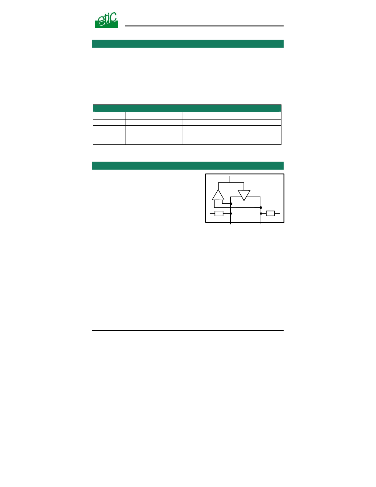
7 RS485 (XSLAN-1230 or -2230)
The RS485 serial interface is
provided on the front panel 2 pins
screw-block.
Polarisation resistors
1 Kohm bus polarisation resistors
are included inside the product.
-
1K 1K
+
SW1
B(+) A(-)RS485
RS485 line adaptation
For a several meters long connection over the RS485 local interface, it is
not necessary to adapt the RS485 line. For a longer distance, connect a
120 Ohm resistor at each end of the line.
XSLAN SHDSL switch User’s guide ref 9014709-02
Page 17
INSTALLATION
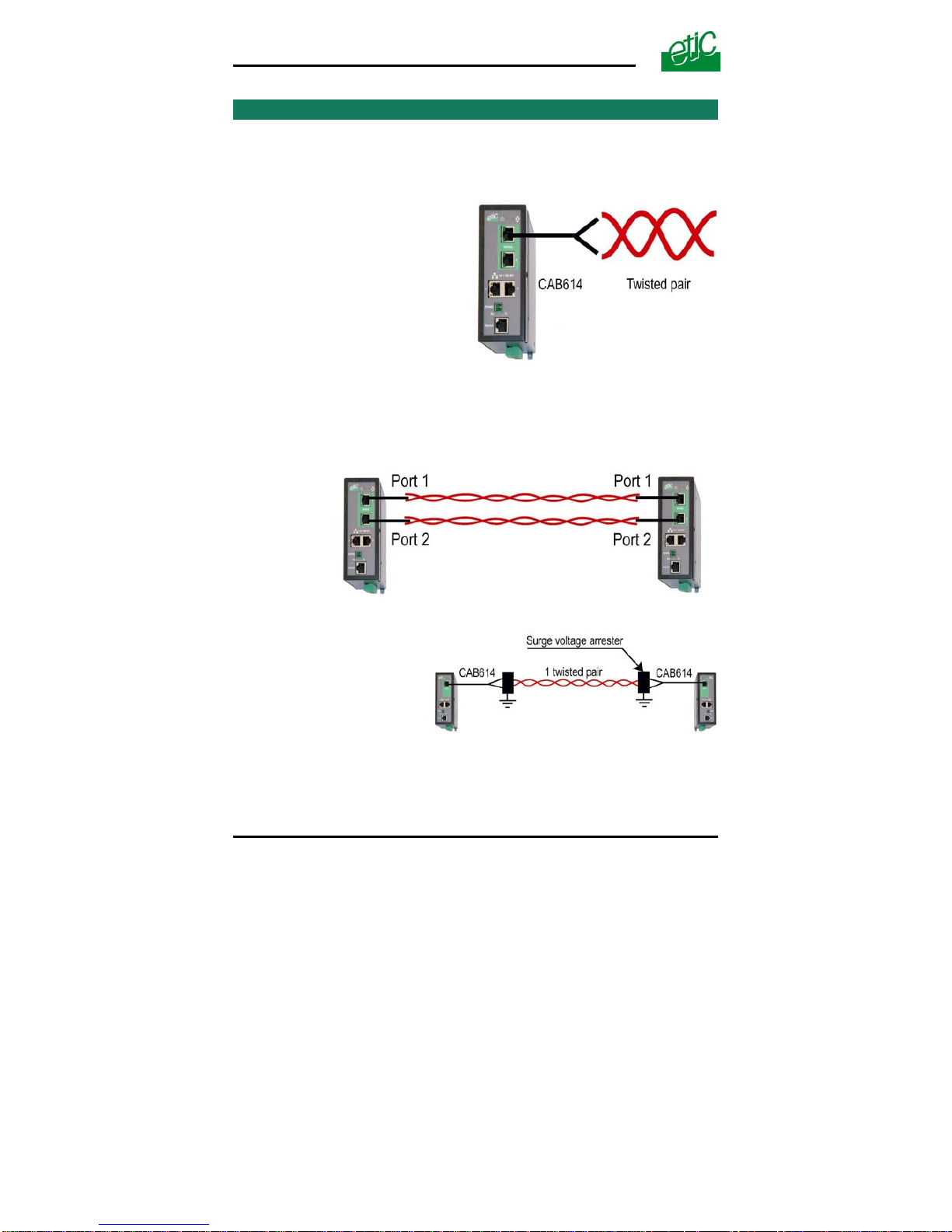
8 SHDSL line
Remark :
For test purpose on a desk, the line can be replaced by any Ethernet
straight cable.
Connecting the XSLAN to the
line
The CAB614 cable allows to
connect the XSLAN to the line.
The cable comes with 2 wires
which have to be connected to
the two wires of the twisted p air.
he 2 wires can be inverted. T
Case of a two twisted pairs connection
ted with two pairs instead of only one.
DSL switch must be necessarily connected to the port Nr 1 of
The XSLAN-2400 or –2220 or –2230 can be connec
The data rate is doubled.
The port Nr 1 of the first SH
the other switch.
urge voltage arrester
e
S
if the line is exposed to th
lightning, we advise to use
an over voltage arrester at
each end of the line.
Page 18 User’s guide ref 9014709-02 XSLAN SHDSL switch

INSTALLATION
We have selected the Phoenix Contact
module TT-2-PE-24D; it must be wired as
indicated opposite.
Line cable shield :
If the line is shielded, the shield must be connected to the earth; only at
one end if it is not interrupted along the line.
XSLAN SHDSL switch User’s guide ref 9014709-02
Page 19
INSTALLATION
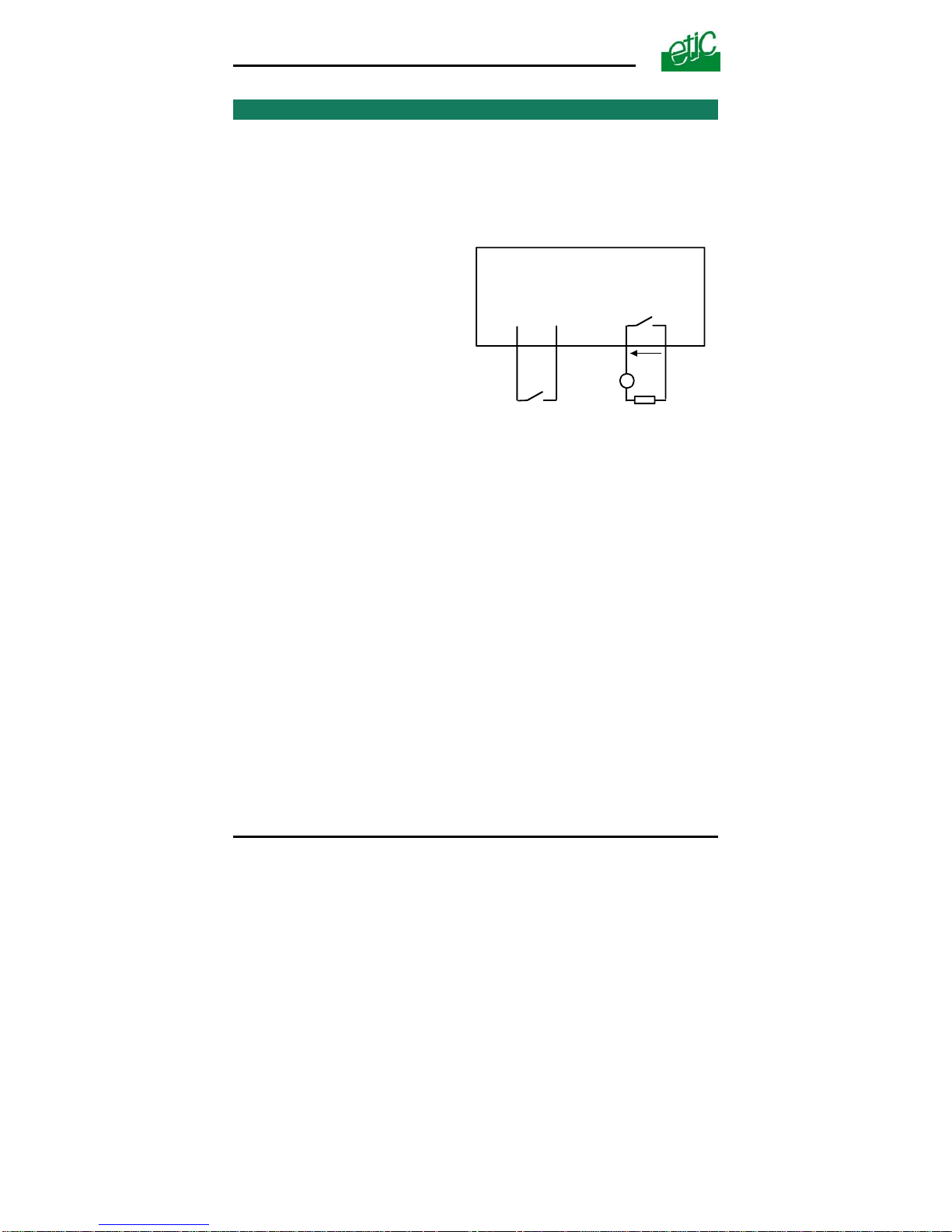
9 Input and output
Input
That input is not isolated.
if it is opened, an SNMP trap will be sent to the SNMP server is that
function has been enabled.
Alarm output
1 relay output is provided to indicate
an alarm.
F+ F-
7
8
Digital output
+
V < 48 VDC
I < 0,5 A
3V3
In
5
6
Digital input
I max = 0,5 A
V
The alarm condition can be
selected using the html server.
The Output is open when the
XSLAN is switched OFF or when
the SHDSL line is not connected.
Page 20 User’s guide ref 9014709-02 XSLAN SHDSL switch
 Loading...