

ETI 54677441, WR-4-57-940-MV-D Use And Care Manual

Model #
54677441
USE AND CARE GUIDE
4 FT. LED HIGH OUTPUT WRAP LIGHT
Part #
WR-4-57-940-MV-D
Questions, problems, missing parts?
Call ETi SSL Customer Service
9 a.m. – 5 p.m., EST, Monday - Friday
1-855-ETI-SSLI (1-855-384-7754)
www.ETiSSL.com
THANK YOU
We appreciate the trust and confidence you have placed in ETi through the purchase of this LED light. We strive to continually create quality
products designed to enhance your home. Visit us online to see our full line of products available for your home improvement needs.
Thank you for choosing ETi!

Table of Contents
Table of Contents ...................................2
Safety Information ..................................2
Warranty ..........................................2
Pre-Installation .....................................3
Planning Installation ...............................3
Tools Required ....................................3
Safety Information
WARNING: Carefully read and understand the information
given in this manual before beginning the assembly and
installation. Failure to do so so could lead to electric shock,
fire, or other injuries which could be hazardous or even fatal.
WARNING: Ensure the electricity to the wires you are
working on is shut off. Either remove the fuse or turn off the
circuit breaker.
WARNING: Changes or modifications not expressly approved
by the party responsible for compliance could void the user’s
authority to operate the equipment.
Package Contents .................................4
Hardware Included .................................4
Installation ........................................5
Care and Cleaning .................................10
Troubleshooting ...................................10
NOTICE: This equipment has been tested and found to comply with the
limits for a Class B digital device, pursuant to Part 15B of the FCC Rules.
These limits are designed to provide reasonable protection against harmful
interference in a residential installation.
This equipment generates, uses and can radiate radio frequency energy
and, if not installed and used in accordance with the instructions, may
cause harmful interference to radio communications.
However, there is no guarantee that interference will not occur in a
particular installation. If this equipment does cause harmful interference
to radio or television reception, which can be determined by turning
the equipment off and on, the user is encouraged to try to correct the
interference by one or more of the following measures:
Ƒ Reorient or relocate the receiving antenna.
Ƒ Increase the separation between the equipment and the receiver.
Ƒ Connect the equipment into an outlet on a circuit different from that to
which the receiver is connected.
Ƒ Consult the dealer or an experienced radio/TV technician for help.
Warranty
This product is warranted for a period of 5 years from the date of original purchase against defects in materials and workmanship. If this
product should fail to operate due to defects in material or workmanship within 60 months of purchase, see www.ETiSSL.com for details.
This product will be repaired or replaced, at ETi’s option. This warranty is expressly limited to repair or replacement of product, and liability
for direct, incidental, or consequential damages is hereby expressly excluded. Some states do not allow exclusions of direct, incidental or
consequential damages, so the above limitation of exclusion may not apply to you. This warranty gives the consumer specifc legal rights,
which vary from state to state. WARRANTY IS VOID IF PRODUCT IS NOT USED FOR THE PURPOSE WHICH THIS PRODUCT IS MANUFACTURED.
2
Pre-Installation
PLANNING INSTALLATION
Before beginning assembly, installation or operation of product, make sure all parts are present. Compare parts with the package
contents list. If any part is missing or damaged, do not attempt to assemble, install or operate the product. Contact customer service
for replacement parts.
NOTE: Keep your receipt and these instructions for proof of purchase.
If you are unfamiliar with electrical installations, we recommend you contact a qualified electrician to do the installation.
NOTE: Two people are recommended for the installation of this light fixture.
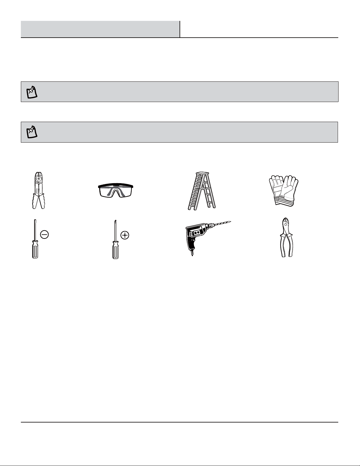
TOOLS REQUIRED
Wire
Strippers
Flathead
Screwdriver
Safety
Goggles
Phillips
Screwdriver
Ladder Gloves
Power Drill
with drill bits
Wire
Cutters
3
Please contact 1-855-384-7754 or further assistance.
www.ETiSSL.com
Pre-Installation (continued)
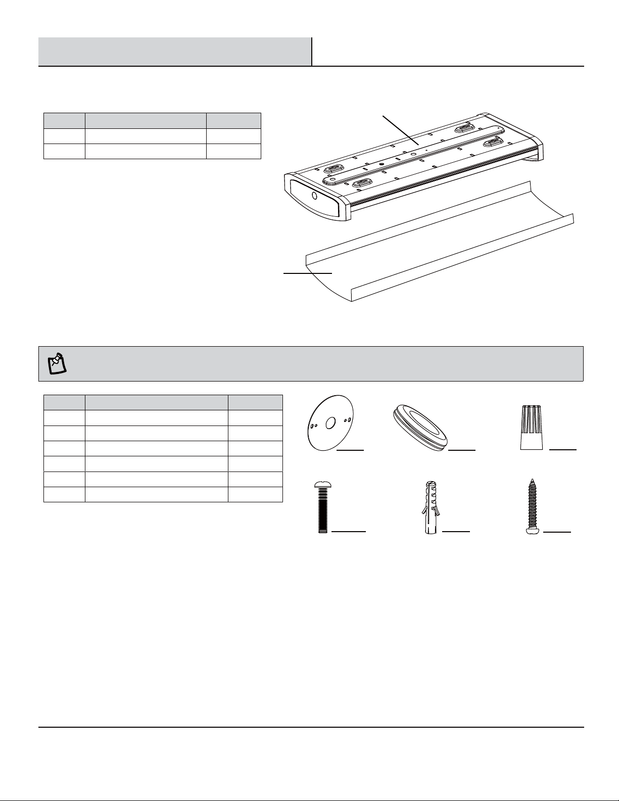
PACKAGE CONTENTS
Part Description Quantity
A LED Wrap Light Housing 1
B LED Wrap Light Diffuser 1
B
HARDWARE INCLUDED
NOTE: Hardware not shown to actual size.
A
Part Description Quantity
AA Mounting Bracket 1
BB Gasket 1
CC Single Wire Connector 5
DD Electrical Box Screw 2
EE Drywall Anchor 4
FF Mounting Screw
4
AA
DD
EE
BB
CC
FF
4
Installation
Select a suitable location that can support the weight of the fixture. Determine the method of mounting before drilling.
WARNING: RISK OF ELECTRIC SHOCK. Ensure the electricity to the wires you are working on is shut off. Either remove the fuse or turn off the
circuit breaker before removing the existing light fixture or installing the new one.
With power disconnected to your electrical box, remove the existing fixture. Make a sketch of how the current fixture is wired (by wire
color) or mark the wires with masking tape and a pencil so you will know how to properly reconnect the wires to the new LED light fixture.
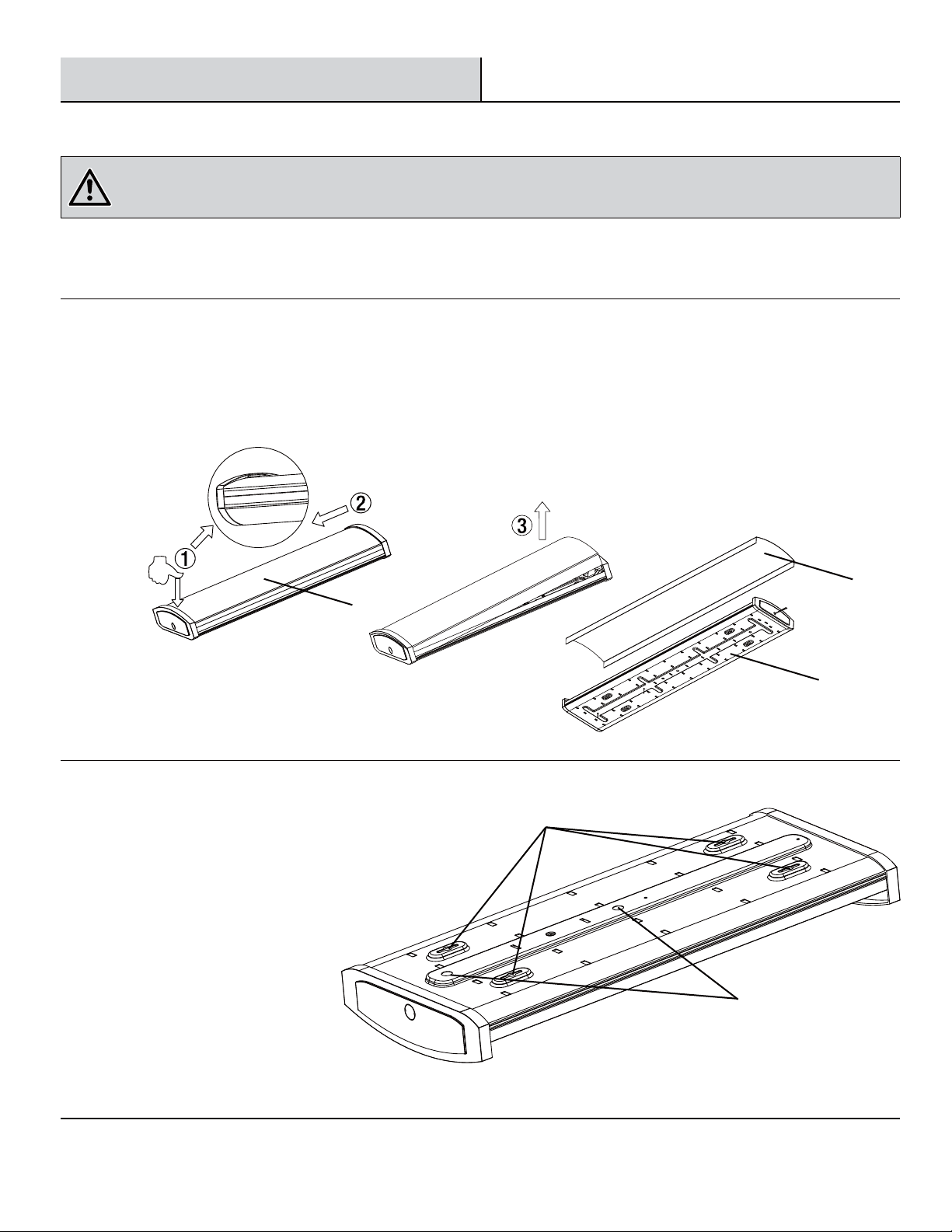
Separating the diffuser from the housing
1
Ƒ Press down gently on one end of the diffuser (B) until you meet with resistance from the bottom of the end cap of the housing (A).
Ƒ Slide the diffuser (B) toward the end being pressed down.
Ƒ Lift the diffuser (B) from the other end, removing it from the housing (A).
Marking the mounting location
2
Ƒ With help from another person, temporarily
hold the fixture housing (A) up to the ceiling to
determine the best mounting position and which
knockout hole to use for wiring the fixture.
Ƒ Mark four keyhole locations for mounting.
B
B
A
Keyholes
Knock out holes
5
Please contact 1-855-384-7754 or further assistance.
www.ETiSSL.com
Installation (continued)
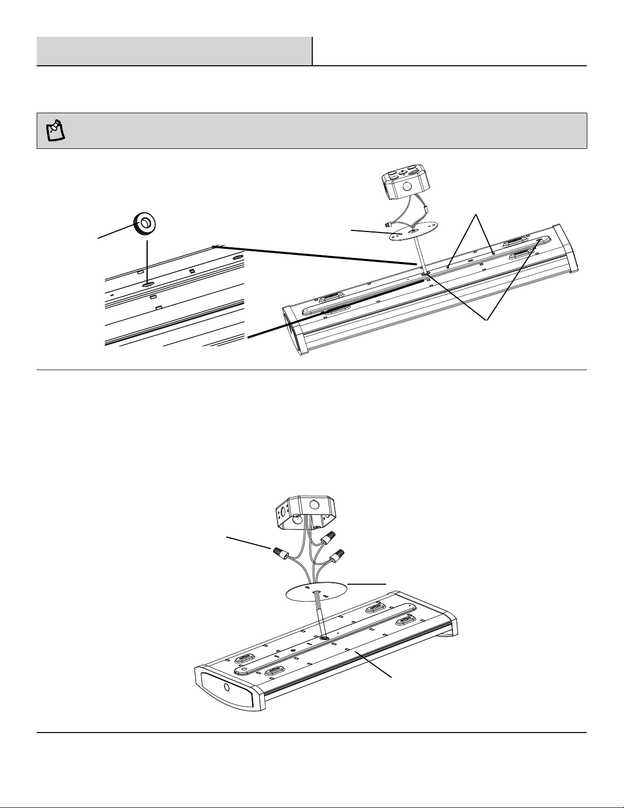
Feeding the wires
3
NOTE: Put the gasket (BB) on any knock out hole of the fixture to better protect the wires.
Ƒ Feed the electrical connection wires through any knock
out hole and then through the mounting bracket (AA). The
connection wires can be held in place by the metal tabs,
if needed.
Metal tabs
BB
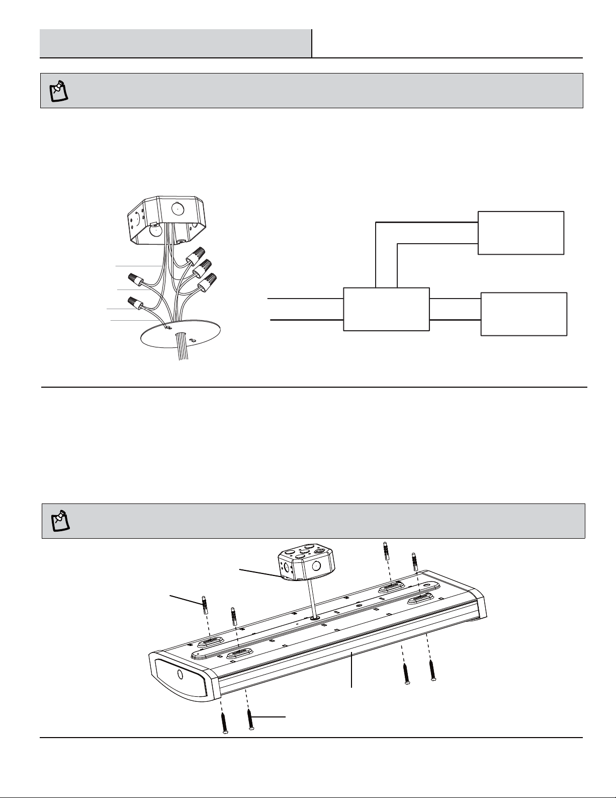
Connecting the wires
4
Ƒ Connect the hot and neutral (black and white) wires from the housing (A) to the same color wires from the
electrical box.
Ƒ Cover the wire connection using the single wire connector (CC).
Ƒ Connect the green wire from the housing (A) to the grounding wire from the electrical box. Secure together
using a single wire connector (CC).
AA
Knock out holes
CC
AA
A
6
Installation (continued)
NOTE: Please refer to below wire and curcuit diagram if end user has demand for the 0-10V dimmer installation.
□
Connect the black wire and wire L together.
□
Connect the white wire and wire N together.
□
Connect the green wire and earth wire together.
□
Connect the purple wire and the anode of the dimmer, and connect the gray wire and the cathode of the dimmer.
□
Finally, fix all of them with single wire connector (CC).
Black(+)
Purple(+)
Anode(+)
Gray(-)
Cathode(-)
White(-)
Green(E)
DIM+
Dimmer
0-10V
-
DIM-
L
N
DIM+
LED Power (DRIVER)
LED+
LED lamp panel
LED-
Attaching the housing to the ceiling
5
Ƒ Drill a 1/8 in. pilot hole into the screw locations marked on the ceiling. You can also use an awl or nail to dimple the screw holes.
Ƒ Install a drywall anchor (EE) and a mounting screw (FF) in each drilled mounting hole, but do not tighten fully.
Ƒ Align the 4 mounting keyholes on the housing (A) with the 4 mounting screws in the ceiling. Once the screw heads are through the
large ends of the keyholes, slide the housing until the heads of the screws slide into the narrow ends of the keyholes.
Ƒ Finish tightening the mounting screws (FF) until the fixture housing (A) is tightly secured to the mounting surface.
NOTE: The drywall anchors (FF) are only to be used for mounting the fixture onto plaster or drywall surfaces.
AA
EE
A
FF
7
www.ETiSSL.com
Please contact 1-855-384-7754 or further assistance.
Installation (continued)
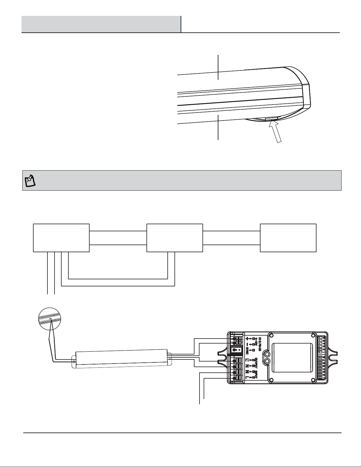
Attaching the diffuser to the
6
housing
Ƒ Insert one end of the diffuser (B) into the
end cap of the housing (A) to the bottom of
the limit part.
Ƒ Push the other end of the diffuser (B) to the
top of the limit part on the opposite end cap.
Ƒ Restore power to the electrical box.
Turn on the light switch on to activate the fixture.
NOTE: This wrap light is compatible for motion sensor, and below circuit wiring diagram is for two types of motion sensor. For the sensor, we
suggest to use ETI SSL brand model: 90600145 (ON/OFF) and 90600144 (0-10V).
When the sensor is 0-10V step-dimming with LED power supply, circuit wiring diagram is as below.Ƒ
A
B
Limit part
N
N (White)
drive+
drive-
B+ (Anode)
B- (Cathode)
L’ (Black)
N (White)
L (Black)
LED+
LED lamp panel
LED-
0-10V
Motion Sensor
DIM+
Step-dimming
0-10V
LED-
Motion Sensor
DIM-
NNL’
L
LED+
LED DRIVER
DIM+
LED Power (DRIVER)
DIM-
L
8
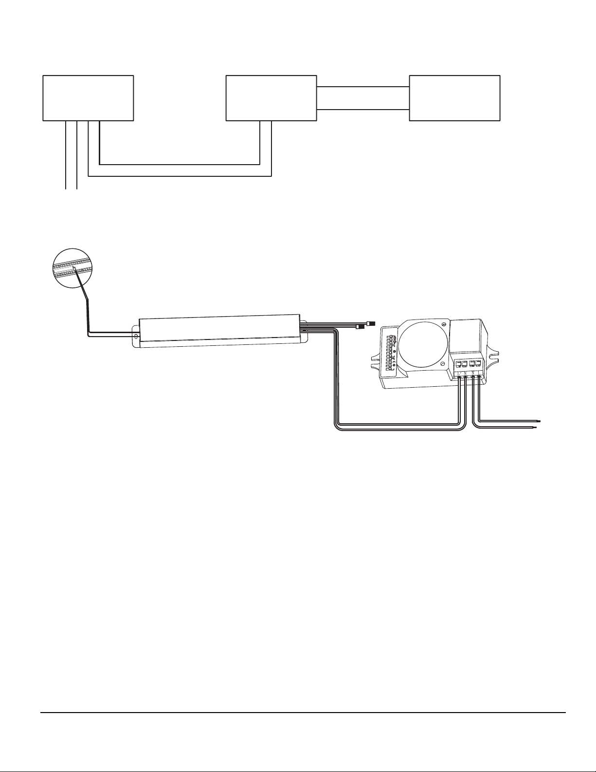
Ƒ
When the sensor is ON/OFF (also plus LED power supply), circuit wiring diagram is as below.
(ON/OFF)
Motion Sensor
NL’
N
L
LED+
LED-
LED DRIVER
DIM+
LED Power (DRIVER)
DIM-
drive+
LED+
LED lamp panel
drive-
NL
B+ (Anode)
B- (Cathode)
LED-
(ON/OFF)
Motion Sensor
L’ (Black)
N (White)
L (Black)
N (White)
9
www.ETiSSL.com
Please contact 1-855-384-7754 or further assistance.
 Loading...