

Page 1
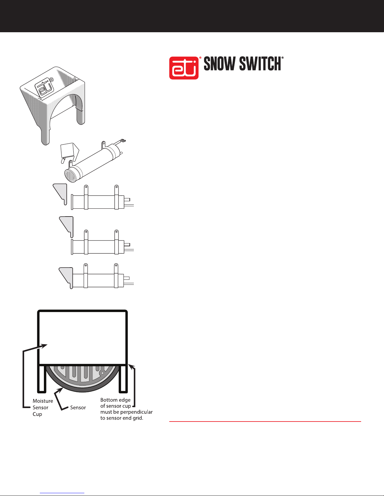
FIGURE 1.
Moisture Sensor Cup.
FIGURE 2. Moisture
Sensor Cup positioned
over grid-end of Sensor.
SENSOR CUP
AUTOMATIC SNOW/ICE MELTING SYSTEM CONTROL PANEL
GENERAL GUIDELINES
An optional moisture sensor cup has been included with this assembly
to enable the ice/snow sensor to work most efciently in the widest
possible variety of weather conditions in which it will be used. Refer
to Figure 1. Specically, the optional moisture sensor cup will keep ice
and dry snow from mounding up over the moisture sensor, limiting
its full effectiveness, especially in areas of extreme cold or high
altitudes. This installation sheet describes the installation and use of
this optional moisture sensor cup.
FIGURE 3. Moisture Sensor Cup
installed over the Sensor.
South Bend, Indiana USA | networketi.com
It is important to keep the gutters clean when using a gutter sensor.
The addition of the moisture sensor cup requires extra care to keep
the cup free of debris.
Note that the use of the optional moisture sensor cup will require that
the gutters be kept as clean and free from leaves and related debris
as possible so that the sensor unit does not run longer than necessary.
PACKING LIST
Part Number Description
23973 Installation Sheet (this document)
23864 Moisture Sensor Cup
MOISTURE SENSOR CUP INSTALLATION MANUAL | PART NO. 23975 REV A
Page 2

INSTALLATION INSTRUCTIONS
QUESTIONS AND COMMENTS
The optional moisture sensor cup can be used either to
retrot an existing moisture sensor or when installing a
new sensor. In either case, the most critical issue regarding
its installation is that the bottom of the moisture sensor cup
must be perpendicular to the grid lines in the sensor end.
To retrot an existing sensor or to t the adapter over a
new sensor prior to installation, perform the steps below.
1. Position the moisture sensor cup over the far end
of the moisture sensor, opposite the end with the
electrical wires. Refer to Figure 2.
2. Align the moisture sensor cup mounting groove over
the anged end of the moisture sensor. The sensor
cup was designed to t and mate snugly over the
moisture sensor ange to help hold it in place.
3. Push the moisture sensor cup down over the moisture
sensor ange until it snaps into position and is
properly seated on the moisture sensor.
4. Once the adapter has been secured in place over
the moisture sensor ange, gently rotate the adapter
in either direction until the bottom of the cup is
perpendicular to the sensor end grid. Refer to Figure 3.
5. With the moisture sensor cup now in place over the
moisture sensor and aligned perpendicular to the
end grid, moisture sensor installation may proceed.
Make sure upon sensor installation to rest the adapter
on its two feet along the bottom of the gutter as this
is the optimum positioning for the proper function of
the moisture sensor cup.
For technical help, questions, or comments concerning
this or any ETI product, contact the Customer Service
Department between 8:00 a.m. and 5:00 p.m. EST.
E-mail: [email protected]
LIMITED WARRANTY
ETI’s two year limited warranty covering defects in
workmanship and materials applies. Contact Customer
Service for complete warranty information.
DISCLAIMER
ETI makes no representations or warranties, either
expressed or implied, with respect to the contents
of this publication or the products that it describes,
and specically disclaims any implied warranties of
merchantability or tness for any particular purpose. ETI
reserves the right to revise this publication, and to make
changes and improvements to the products described
in this publication, without the obligation of ETI to notify
any person or organization of such revisions, changes or
improvements.
Copyright © 2019 ETI,® All rights reserved.
South Bend, Indiana USA | networketi.com
2
MOISTURE SENSOR CUP INSTALLATION MANUAL | PART NO. 23975 REV A
 Loading...