

Page 1
AUTOMATIC SNOW/ICE MELTING SYSTEM CONTROL PANEL
PACKING LIST
QTY. PART NO. DESCRIPTION
1 23736 PD Pro
1 23731 Accessory Kit
1 24455 PD Pro Installation Sheet (this document)
1 23735 PD Pro Instruction Manual
The Snow Switch Model PD Pro Automatic Snow and Ice Melting System is permanently connected equipment
and does not have an internal disconnect device. A readily accessible disconnect device, short circuit, and current
NOTE:
protection shall be provided and are not supplied by ETI When power is applied, the system will start.
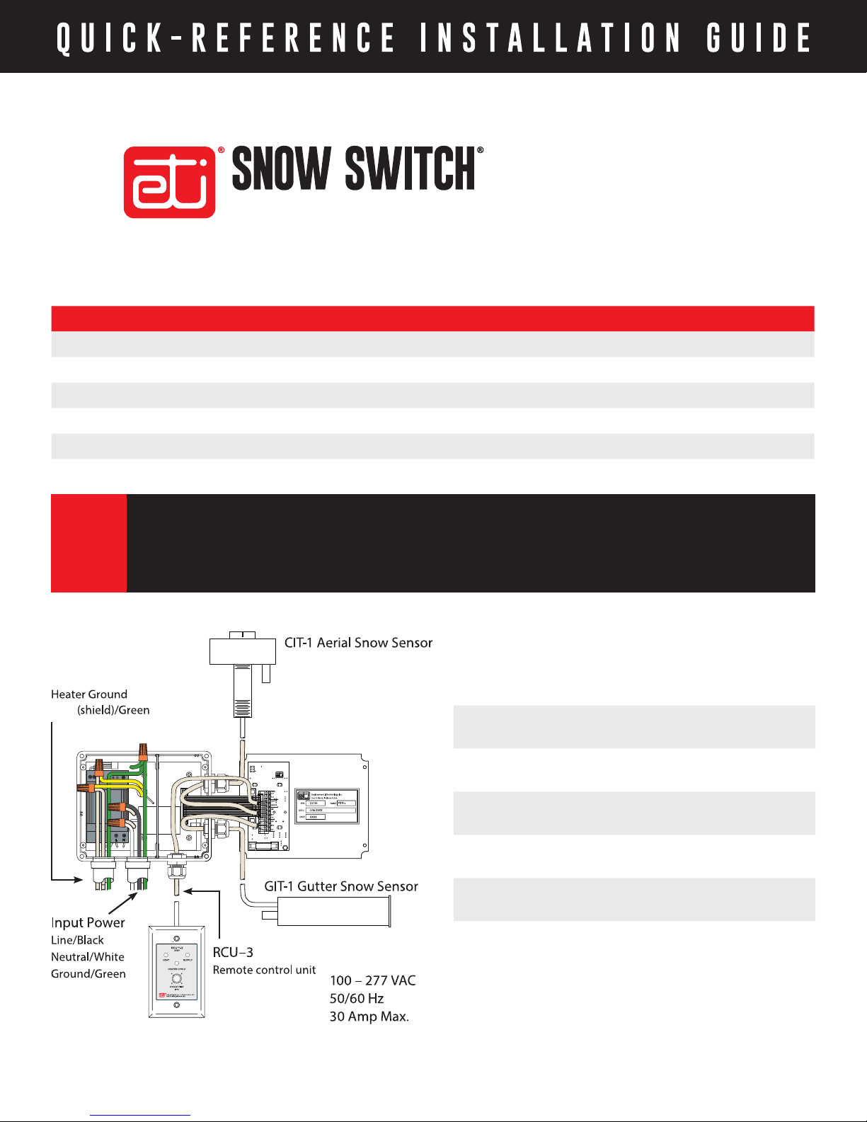
MODEL PD PRO
To Heater Cable
Heater Load Line / Yellow
Heater Load Neutral / Yellow
Heater Ground (shield)/Green
Power Cable
(provided by customer)
Sensor Wiring #18 AWG jacketed,
Heater Cable
(provided by customer)
Remote Wiring #22 AWG jacketed,
Temperature Sensor
Assembly Wiring
Size for 30 Amp
maximum load
3-conductor
Size to system load
2-conductor
#22 AWG jacketed,
2-conductor
South Bend, Indiana USA | networketi.com
SNOW/ICE CONTROL INSTALLATION GUIDE | PART NO. 24455 REV D
Page 2
Cable Function Wire Lead Connect To:
INPUT POWER (provided by customer) Line 1
OUTPUT TO HEATER
(provided by customer)
South Bend, Indiana USA | networketi.com
Line 2 / Neutral Ground
Heater Load Line
Heater Load Neutral
Heater ground (Shield)
2
SNOW/ICE CONTROL INSTALLATION GUIDE | PART NO. 24455 REV D
Black
White
Green
Yellow
Yellow
Green
Page 3

SAFETY & WARNINGS
1. Even when the heat tapes are disconnected, as long
as the circuit breaker is on and power is running to
the unit, voltage is still being applied to the yellow
heat tape leads. Therefore, never touch the ends of
the yellow leads or let the two leads touch each other.
Do not let the two yellow heat tape leads contact any
component inside the unit.
2. Any installation involving electric heater wiring must
be grounded to earth to protect against shock and
re hazard. Suitable ground fault detection and
interrupting systems must be in use at all times to
reduce shock and re hazard and to protect personnel
and equipment.
3. Electric wiring to heating elements must be installed
in accordance with National Electrical Code (NEC)
requirements, as well as other local and applicable
electrical codes and third party standards.
4. Only UL listed, 4X, raintight conduit hubs and cable
glands are to be used. The hub is to be connected to
the conduit of a rigid conduit system before the hub
is connected to the enclosure.
5. Ensure a sealed, watertight installation. Waterproof all
cable runs, seal all box joints, and properly terminate
wiring.
6. Shut off system circuit breaker prior to beginning
installation.
PRIOR TO INSTALLATION
1. Install & service this device only if a qualied electrician
trained to perform such work.
2. Refer to page 8 of the PD Pro Instruction Manual to
learn about optional equipment available for the PD
Pro system which might be of interest to you.
3. Before beginning installation, lay out the system
components in their approximate location on the site
to help you visualize the system and evaluate exact
component and junction box placement, as well as
required cable and conduit lengths.
4. It is recommended to read these installation instructions prior to beginning installation.
INSTALLATION
1. Install the control box. Locate and install the control
box on a wall using the box itself as a template to
determine the mounting hole footprint. Install the
box to a solid, stable surface capable of supporting
four times the weight of the box, or about 20 pounds.
Use all four mounting holes. Install the control box
to the wall using heavy-duty mounting hardware
long enough to fasten the box securely. Do not fully
tighten the mounting hardware at this time. Leave the
mounting hardware loose enough to work the conduit
into place. Hardware will be fully tightened following
installation of the conduit.
2. Once the control box is installed but with the
mounting hardware not yet fully tightened, with the
circuit breaker off, install the sensor(s) and sensor
cables. Refer to the installation instructions provided
with each sensor. For greater system exibility, it is
recommended to route the sensor cables through
conduit. If installing an extension onto the sensor
cable(s), a junction box is required in accordance with
applicable codes. Feed the sensor cable through the
weather-tight connection ports on the right side of
the control box, then connect the leads to the circuit
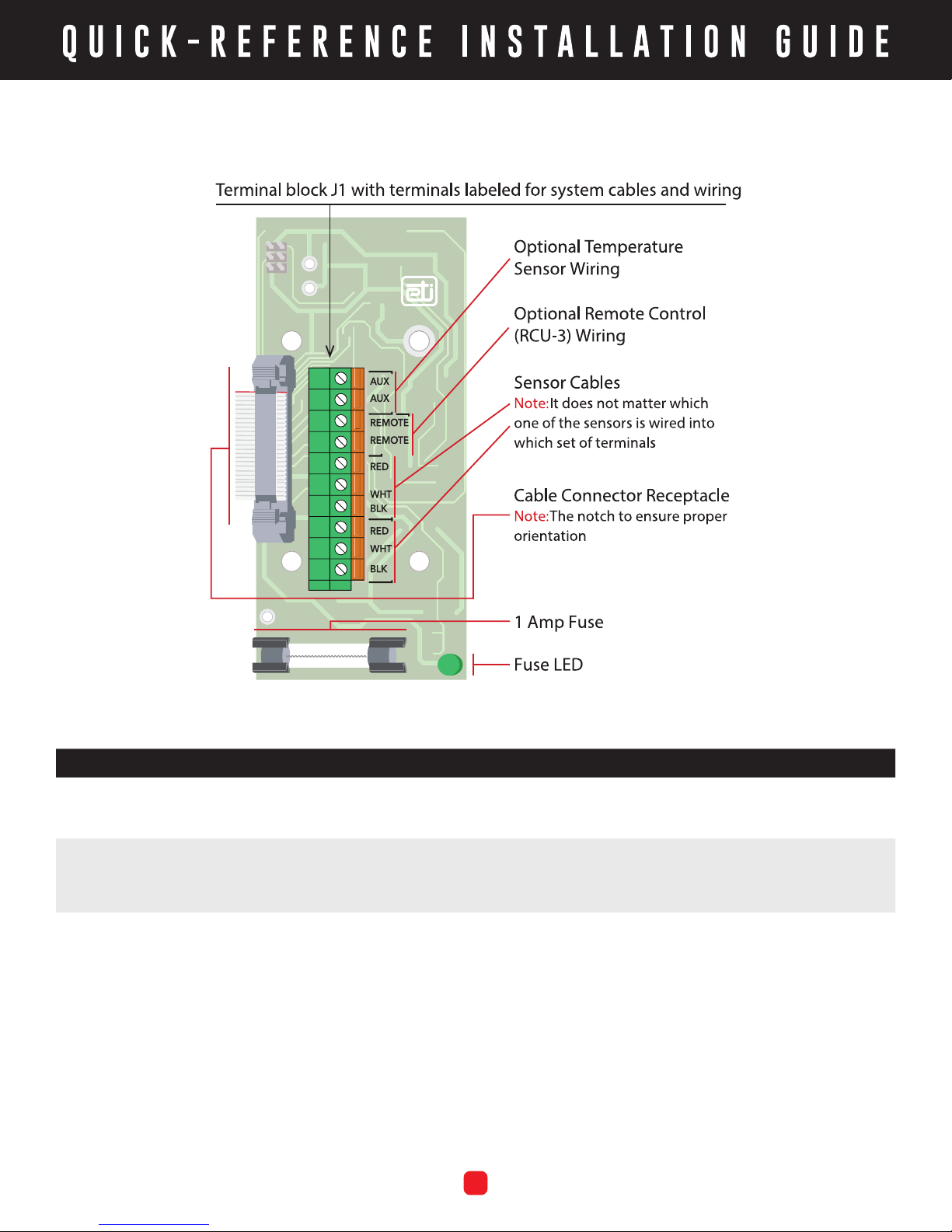
board terminals labeled RED, WHT, and BLK. If using
more than one sensor, it does not matter which sensor
goes to which set of terminals.
3. With the circuit breaker off, install the heat tape
(heater cables). Install the heat tape in accordance
with National Electrical Code (NEC) and heat tape
manufacturer’s specications and requirements,
as well as other local and applicable building and
electrical codes and standards. If using a SIT–6E
pavement-mounted sensor, run the heat tape so it
doesn’t touch the SIT–6E cable. Refer to the schematic
diagram on this Installation Sheet. Route the heat
tape through conduit as directed by the heat tape
South Bend, Indiana USA | networketi.com
3
SNOW/ICE CONTROL INSTALLATION GUIDE | PART NO. 24455 REV D
Page 4

manufacturer, then connect the heat tape leads to
the two yellow wires inside the control box. The
Heater Load and Heater Load 2 yellow wires are
interchangeable; it doesn’t matter which heat tape
lead goes to which of the yellow wires.
4. As applicable, install optional device(s) and associated
cable(s). Refer to the schematic. Route the cable(s)
through conduit and into the control box as shown,
then connect the temperature sensor leads to the
circuit board terminals labeled AUX and the remote
control leads to the terminals labeled Remote.
5. With the circuit breaker off, install the power cable.
As shown in the wiring charts, the power cable is
provided by the customer. Size the cable for a 30
Amp maximum load. Run the cable through conduit
and connect the leads to the control box wiring. The
line is black, neutral is white, and ground is green. The
PD Pro has no power switch so remember that power
is running to the system as soon as power is applied.
Note: ETI recommends using a CIT-1 in conjunction
with either a SIT-6E for pavement melting or a GIT-1
for gutter and roof melting.
CONTACTING CUSTOMER SERVICE
For technical help, questions or comments concerning
this product or any ETI product contact Customer Service
8:00 a.m. - 5:00 p.m. EST.
Email: [email protected]
Web: networketi.com
Mail: ETI
1850 North Sheridan Street
South Bend, IN 46628
6. With cabling routed through conduit, install the
conduit runs to the control box. Once conduit is secure,
fully tighten the control box mounting hardware and
re-assemble control box panels and cover in their
original location.
7. At this time, turn the system circuit breaker back on.
The green SUPPLY LED light should be on and will
always be on while power is running to the control.
8. As directed on page 17 of the PD Pro Instruction
Manual, perform Post-Installation Testing as described,
depending which sensors are used in your system. It
is important to perform this testing prior to operating
the system.
9. Once all system components have been properly
installed and tested, the circuit breaker has been
turned on, and power is running to the control box,
the system is operational. Now, rotate the Hold-On
Time control knob on the face of the control box to set
the desired duration of the heating cycles which will
begin automatically as described in the Instruction
Manual, or manually by pressing the Heater Cycle
button, and will run for the length of time set, or until
the Heater Cycle button is pressed.
LIMITED WARRANTY
ETI’s two year limited warranty covering defects in
workmanship and materials applies. Contact Customer
Service for complete warranty information.
DISCLAIMER
ETI makes no representations or warranties, either
expressed or implied, with respect to the contents
of this publication or the products that it describes,
and specically disclaims any implied warranties of
merchantability or tness for any particular purpose. ETI
reserves the right to revise this publication, and to make
changes and improvements to the products described
in this publication, without the obligation of ETI to notify
any person or organization of such revisions, changes or
improvements.
Copyright © 2019 ETI,® All rights reserved.
South Bend, Indiana USA | networketi.com
4
SNOW/ICE CONTROL INSTALLATION GUIDE | PART NO. 24455 REV D
 Loading...