

Page 1
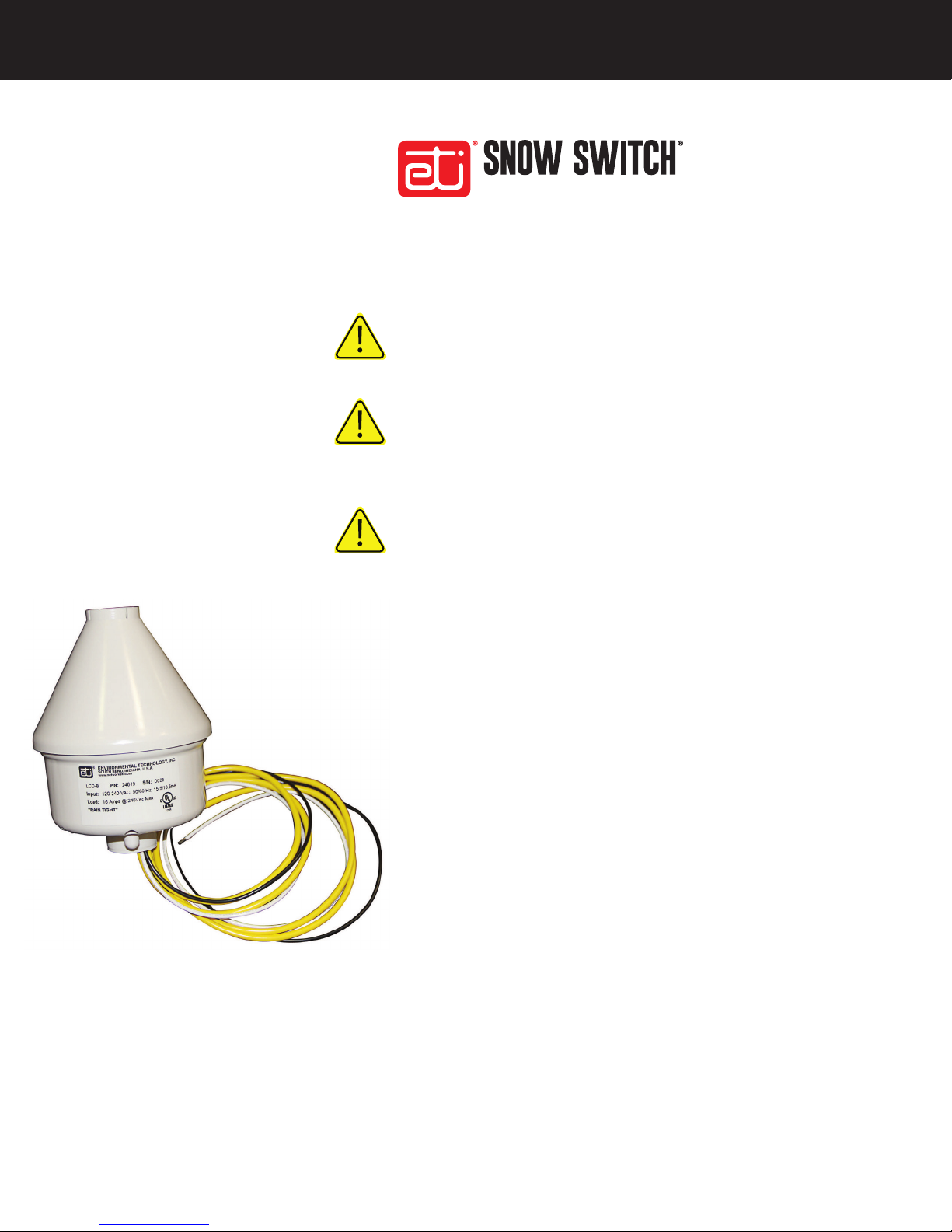
MODEL LCD–8
AUTOMATIC SNOW/ICE MELTING SYSTEM CONTROL PANEL
SAFETY
Make all electrical connections in compliance with the National Electrical
Code (NFPA 70) and local electrical code. If you have questions
concerning the installation or application, contact Customer Service.
Abnormal Odor or Smoke
In the event of smoke or a burning or abnormal odor, immediately
interrupt power to the unit by unplugging the unit or by turning off the
circuit breaker protecting the unit.
Electrical Shock / Fire Hazard
Even when the snow melting elements are disconnected, as long as the
circuit breaker is on and power is running to the unit, voltage is still
being applied to the system’s yellow leads. Therefore, never touch the
ends of the yellow leads or let the two leads touch each other. Do not let
the two yellow leads contact any component inside the unit.
Any installation involving electric heater wiring must be grounded to
earth to protect against shock and re hazard. Suitable ground fault
detection and interrupting systems must be in use at all times to reduce
shock and re hazard and to protect equipment.
Electric wiring to heating elements must be installed in accordance
with National Electrical Code (NEC) or Canadian Electrical Code (CEC)
requirements and all other local and applicable electrical codes and
any third party standards. Follow the installation instructions contained
herein and those provided by the heater manufacturer.
Use a GFEP (Ground Fault Equipment Protection) circuit breaker on
each branch circuit connected to the ice melting system. Clearly label
each circuit breaker with its function. This is vitally important when there
is more than a single point of disconnect.
Size the circuit breaker in accordance with the size of the expected load.
The maximum current load for the LCD-8 is 16 Amp resistive. This product
is intended for use in residential or light commercial applications.
South Bend, Indiana USA | networketi.com
SNOW/ICE CONTROL INSTALLATION MANUAL | PART NO. 24782 REV C
Page 2

Make certain that the heater shield is properly grounded.
Failure to do so may result in damage to the equipment
or re.
Following installation and prior to beginning system
operation, refer to and perform the Post-Installation Tests
(page 12) described in this manual.
ADDITIONAL INFORMATION
More information is made available regularly through
our website, www.networketi.com. Please visit us online
for Data Sheets, Manuals, White Papers, technical articles,
and more. The most current and up to date version of this
and every other manual for our products can be found in
Acrobat (PDF) format to view online or to print. This is to
assist you in installing and using our products to the best
effect possible. If you have any comments about this or
any other product from ETI, please contact us.
PRODUCT OVERVIEW
The Snow Switch® Model LCD–8 (Figure 1) is a
congurable aerial snow melting system controller which
makes automatic snow melting a cost-effective alternative
in even the smallest applications. Heaters operate at
temperatures below the LCD-8’s congurable set point,
pre-programmed to 38°F (3.3°C), only when required.
The adjustable hold-on period, pre-programmed to 3
hours, continues heater operation after snow stops to
ensure complete melting. The LCD–8 controller includes
an internal magnetic reed switch used for manual heater
cycling and conguring the controller’s operational
temperature set point and hold-on time.
The LCD–8 controller is available as a model which
operates from either an automatic selecting 100VAC –
240VAC or as a model which operates from 24VAC. These
two voltage options combine with the congurable hold-
on time and temperature set point to meet the need of a
wide number of applications using just two part numbers.
FIGURE 1. LCD-8
inductive. The operating temperature range extends from
–40°F to 140°F (–40°C to 60°C). The redesigned, patent
pending, rugged polycarbonate enclosure provides
excellent protection at temperature extremes, while
allowing snow to shed to prevent iglooing over the
moisture sensor.
The internal magnetic reed switch allows for both
conguration and manual heater operation without the
need for external switches—which are susceptible to
damage—or the need to open the enclosure.
Verifying system functionality after installation or when
troubleshooting used to require spray circuit cooler
or ice for controller activation. The Sno-Test™ feature
eliminates this need by performing a self-test after power
application and operating heaters in a unique pattern for
a few seconds. Reading the test results takes only an AC
voltmeter or clamp-on ammeter.
It controls heater loads up to 16 amps resistive or 3 amps
South Bend, Indiana USA | networketi.com
A congurable snow sensor with two light-emitting diode
2
SNOW/ICE CONTROL INSTALLATION MANUAL | PART NO. 24782 REV C
Page 3
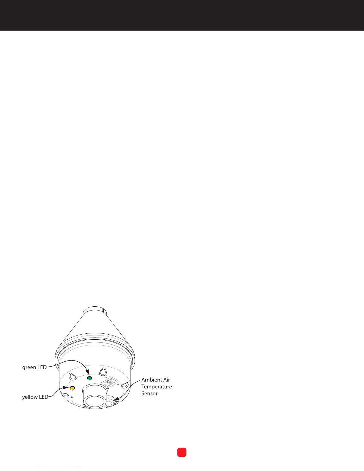
(LED) indicator lamps (Figure 2), the LCD-8 features a
hold-on timer which allows its system to operate to a drier
surface after melting snow.
• The hold-on timer can be congured for off, 1 hour, 3
hours or 5 hours. The operating temperature can be
congured for none (precipitation sensor), 36°F, 38°F
or 40°F.
• The low-temperature lockout (17°F/-8.3°C), which
disengages unit operation, can be enabled or not.
• Pre-programmed conguration: 38°F (3.3°C) operating
temperature; 3 hour hold-on; no lockout.
• The LCD-8 uses an internal magnetic switch. The user
swipes a magnet externally across this switch to start a
hold-on cycle or to terminate a running hold-on cycle.
This switch may also be used to recongure the unit, or
to view the current conguration.
• The green LED, ordinarily on steady, blinks to indicate a
concern with the unit. This LED is also used in the LCD8’s conguration process.
Immediately upon receipt, inspect the container and
packing material for any noticeable damage. Unpack the
unit, taking care not to damage the packing materials.
Conrm all components noted in “Packing List” above
are included. Save the shipping container and related
materials until normal operation has been established.
If the unit must be returned, take care to ensure that it is
repackaged as it was received.
As soon as the unit arrives at your facility, inspect it for
mechanical damage. If any of the following problems is
found, contact ETI, Customer Service immediately:
• contents incomplete or incorrect;
• internal or external mechanical damage; or
• defective operation.
ETI Customer Service is available between 8:00 a.m. and
5:00 p.m. Eastern Time. In the event of shipping damage,
keep the packing materials for inspection by the carrier.
• The yellow LED indicator is lit whenever the output
relay is powered (“on”).
• There is an initialization period where the heaters are
tested.
UNPACKING THE LCD-8
RETURNS AND REPLACEMENT PART PURCHASES
Equipment cannot be returned for credit once it has
been installed. ETI will repair or replace faulty equipment
under warranty. Prior to removal of equipment for
warranty return, please contact ETI Technical Support for
troubleshooting assistance.
Before returning a unit to ETI, obtain a Return Merchandise
Authorization from our Customer Service Department,
available between 8:00 a.m. and 5:00 p.m. Eastern Time. If
possible, use the original container and packing materials
when packing the unit for shipment. It is important to
mark the Return Merchandise Authorization clearly
on the outside of the shipping container so that it may
be correctly processed upon receipt at Environmental
Technology.
For more information about replacement parts or for a
replacement Manual, please visit www.networketi.com.
FIGURE 2. LCD-8 LEDs
South Bend, Indiana USA | networketi.com
3
SNOW/ICE CONTROL INSTALLATION MANUAL | PART NO. 24782 REV C
Page 4
INSTALLATION
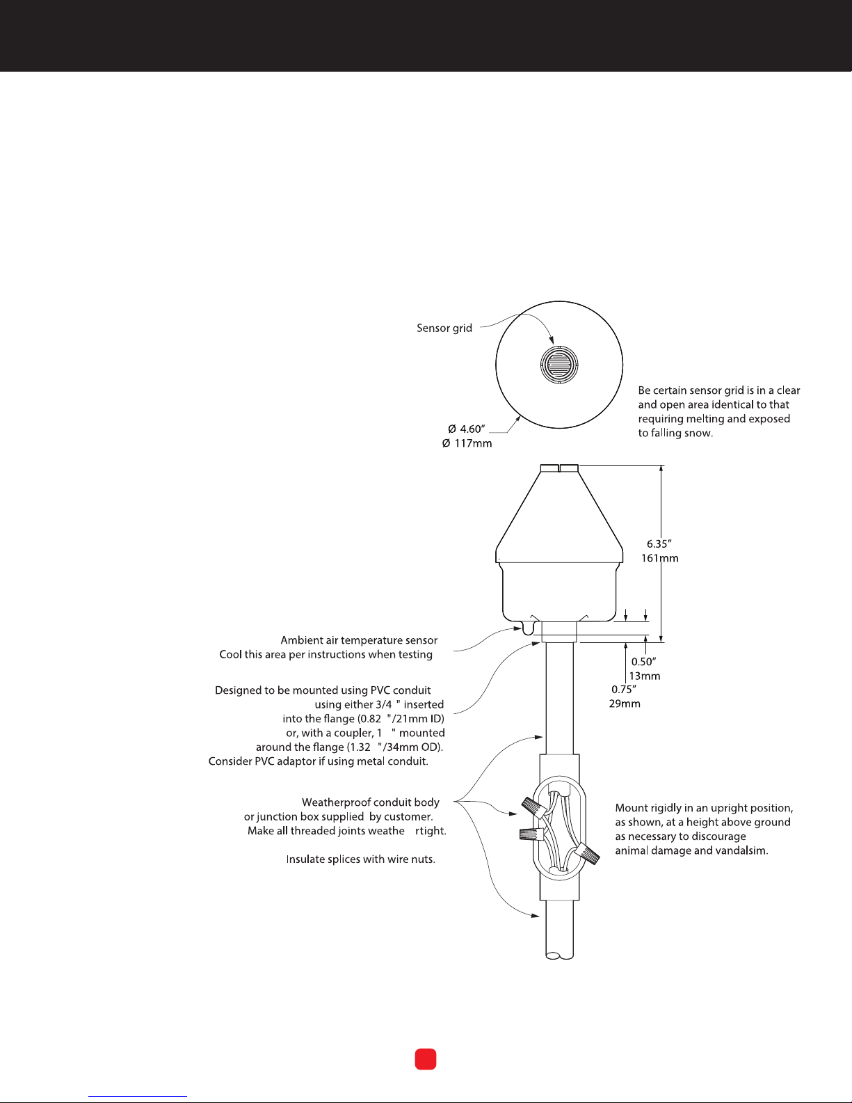
With user-supplied hardware, mount the LCD-8 securely
in an upright position (sensor grid at top; see Figure 3)
in a clear and open area typical of the area to be melted,
either above the roof line or removed from the building
and exposed to, rather than protected from, falling snow.
AVOID: OVERHEAD TREES, SHRUBS, WIRES, EAVES, ETC.,
AND FALLING OR BLOWING DEBRIS.
AVOID: VEHICLE AND FOOT TRAFFIC. DO NOT CREATE A
SAFETY HAZARD.
AVOID: EXPOSURE TO ARTIFICIAL HEAT SOURCES AND
EXCESSIVE SHOCK AND VIBRATION.
The LCD-8 also should be positioned at a height above
ground that reduces, eliminates or discourages damage
caused by animals or vandals.
South Bend, Indiana USA | networketi.com
FIGURE 3. LCD-8 installation
4
SNOW/ICE CONTROL INSTALLATION MANUAL | PART NO. 24782 REV C
Page 5
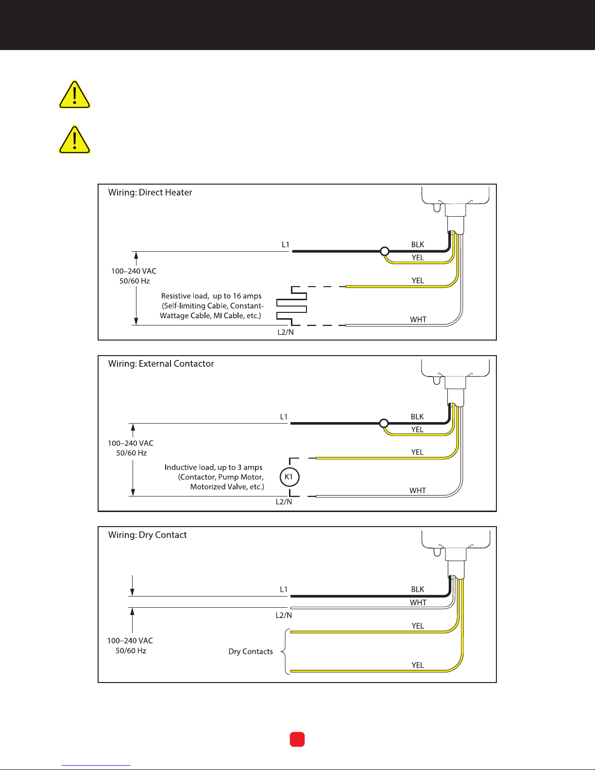
Install in accordance with the requirements of all applicable electrical and building codes and
regulations. Ensure that all conduit and cable terminations are watertight.
NEC Article 426.28 requires Equipment Ground Fault Protection (GFEP) for Ice and Snow Melting
Equipment. This functionality is not provided as part of this controller and shall be provided as part
of the overall system.
South Bend, Indiana USA | networketi.com
FIGURE 3B - LCD WIRING DIAGRAMS
5
SNOW/ICE CONTROL INSTALLATION MANUAL | PART NO. 24782 REV C
Page 6

INITIALIZATION SEQUENCE
INITIATING HOLD-ON STATE
Upon power up, the LCD-8 performs an initialization
sequence, allowing a user or technician to verify its
operation.
First, the interna relay energizes for ten seconds. Next,
the relay powers off and the cup heaters energize for ten
seconds. Finally, both are off for another ten seconds.
During this time, the green LED blinks slowly—one (1)
second on, one (1) second off. Normal operation follows.
When energized, the controller’s green LED is on
continuously. During an alarm condition, the green LED
blinks quickly, alternating between on and off twice a
second. Exceptions are when the green LED conveys
information during the conguration process or when the
unit is in an automated testing device.
When the system detects moisture and the ambient
temperature is below the operating temperature, if there
is one, this denes a “snow” event. For a precipitation
sensor (operating temperature off), moisture is detected
at any temperature: this could be snow or rain.
The user can also swipe the magnet to start a hold-on
cycle or to terminate a hold-on cycle. If a manual cycle is
started, it operates for the normal hold-on duration (note:
if the hold-on time is set to 0, operation lasts one hour).
However, if the ambient temperature is above 50°F when
the cycle starts, the cycle duration is ten (10 ) minutes. If the
temperature rises above 50°F during the cycle, operation
truncates to 10 minutes. This 10-minute constraint is only
for manually-triggered hold-on cycles; a cycle resulting
from snow proceeds for the full duration. Note: this
does not apply to a precipitation sensor.
SPECIAL CASE: HOLD-ON TIME IS 0
For the special case that only occurs with a manual swipe
when the hold-on time is set to zero (0), the heater operates
for at least one hour, even if there is a snow condition. In
terms of a strict state description in this one case, a snow
condition does not cause the system to enter the snow
state, but rather to stay in the hold-on state. If the snow
remains after the one hour, the heater remains energized.
FOUR STATES OF LCD-8 CONTROLLED SYSTEM
The system can be in one of four states, three with lockout
disabled or one in lockout enabled:
• Idle: the LCD-8 monitors during conditions lacking
moisture and/or cold air temperature
• Call for Heat: the LCD-8’s sensors recognize snow or
ice as moisture
• Holding: the LCD-8 continues system operation for
hold-on duration unless snow begins again; when
hold-on time is over or parameter is set to zero (0),
systems returns to Idle state
• Lockout enabled: low-temperature lockout, where
temperature is too cold for system to operate effectively
and energy is conserved
The heater is on during a snow event or within its
holding state.
In the “enabled” Lockout state, the heater is not on. When
snow is detected, the system enters the Snow state if
the ambient air temperature is above 17°F, but it enters
the Lockout state instead if the temperature is below
17°F. Additionally, this Lockout state is entered if the
temperature falls below 17°F during an automatic hold-on
cycle. If the temperature rises above 17°F in the Lockout
state but with no moisture detected (not snowing), the
hold-on timer is restarted. In the Lockout state, the heater
is not on.
If in the Idle state and the temperature is below 17°F
when a magnet swipes the magnetic switch, the system
initiates its manual cycle as usual. If the temperature falls
below 17°F during the cycle, it is ignored. If the unit is
in the Lockout state and the user swipes the magnetic
switch, the temperature reading is ignored. This will be
maintained until the end of the snow event (that is, until a
return to the Idle state).
South Bend, Indiana USA | networketi.com
6
SNOW/ICE CONTROL INSTALLATION MANUAL | PART NO. 24782 REV C
Page 7
The override ends when the heaters turn off. However, if
a manual cycle is initiated when the environment is frigid,
and then snow starts, the heaters remain energized until
the snow stops and for the hold-on time thereafter.
Note: Avoid selecting both low-temperature lockout
and a hold-on time of zero (0) hours, as the heaters
may not energize.
ALARMS
When the LCD-8 operates normally, its green LED is lit
continuously. Under an alarm condition, this LED will ash
rapidly—on and off twice a second. The alarm may or may
not inhibit operation, depending on circumstances.
Three possible conditions exist which initiates an alarm:
• Bad cup thermistor. If the cup thermistor is bad, the
unit will not do automatic snow melting. The rationale
is that we can’t turn on the cup heater without risking
damage to the unit; and if snow or freezing rain falls
with the cup cold, it may stay there for weeks, and the
unit would never shut off. The manual hold-on cycle
will work.
• Bad ambient thermistor. If the ambient thermistor is
bad, the unit will operate normally if it is congured
as a precipitation sensor; if it is congured as a snow
sensor, it will not do automatic snow melting. The
manual hold-on cycle will work.
• Corrupted conguration. If the conguration is
corrupted, the unit will operate under its factory
preset conguration. The bad thermistor alarms will
clear if the thermistor repairs itself. The corrupted
conguration alarm will clear if the unit is recongured:
in that case the user is advised to cycle power,
conrming reconguration.
GREEN LED PULSE PATTERN
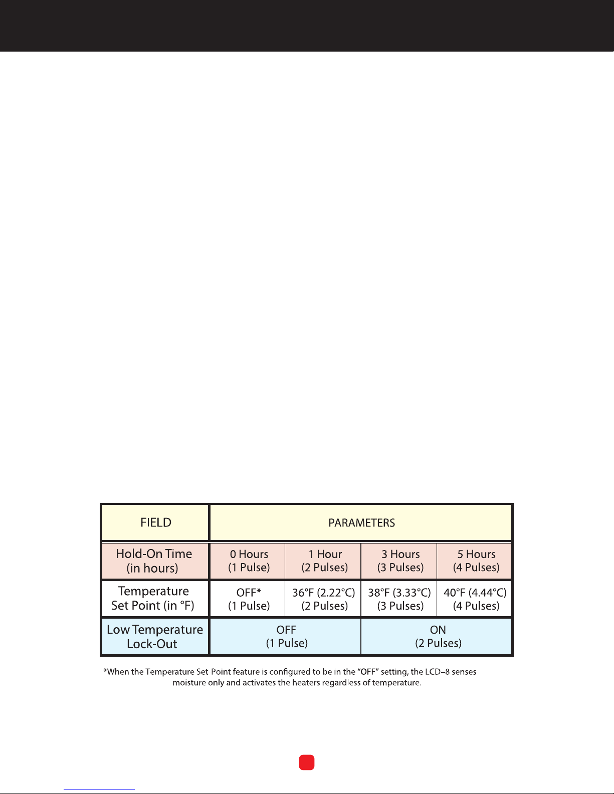
Prior to learning how to change the conguration of the LCD–8, it is rst necessary to
understand how the device communicates with the user; see Table 1. As there is no display
on the unit, the only means of communicating with the device is to carefully observe the
pulse pattern of the green LED.
TABLE 1. LCD–8 Conguration options and green LED pulse pattern
South Bend, Indiana USA | networketi.com
7
SNOW/ICE CONTROL INSTALLATION MANUAL | PART NO. 24782 REV C
Page 8
LCD-8 MAGNETIC REED SWITCH
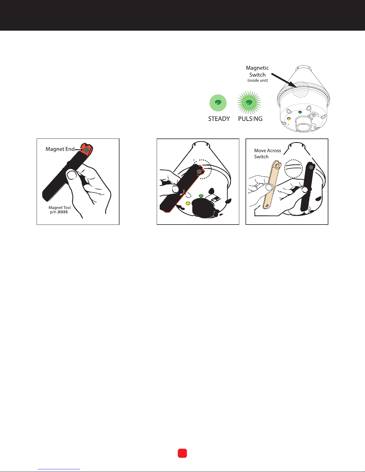
The LCD-8 uses an internal magnetic reed switch (Figure
11), approximately located just below the conical top and
above the green LED. The user swipes a magnet (Figure
5) externally across this switch (Figure 6) to start a hold-on
cycle or to terminate a running hold-on cycle. The magnetic
switch determines whether the user’s action “swipes” or
“holds” the magnet during LCD-8 conguration.
FIGURE 11. Magnetic Reed Switch (internal)
FIGURE 5. Magnet (external) similar to one
at the end of the Magnet Tool, p/n 24888
FIGURE 6. Positioning (left) and swiping (right) the Magnet over the
internal Magnetic Reed Switch
LCD-8 CONFIGURATION
The user is able to congure three operating parameters
on the Snow Switch Model LCD–8. These are:
• the hold-on time in hours;
• the temperature set point in degrees Fahrenheit; and
• low temperature lock-out operation.
The denitions of each of these parameters, as well as how
to determine their current setting and how to change those
settings, will be explained in this section of the manual.
HOLD-ON TIME
Hold-on time refers to the number of hours that the
heaters will continue to operate once the unit no longer
detects precipitation. Hold-on time ensures that not only
is all the snow melted from the protected surface, but
also that the system continues to dry and evaporate the
surface without refreezing. The factory pre-programmed
hold-on time setting is 3 hours.
TEMPERATURE SET-POINT
The temperature set-point refers to the temperature at
which the LCD-8 activates the heaters given the presence
of moisture. The factory pre-programmed temperature
set-point is 38°F (3.33°C). On the “None” setting (Value
1), the controller activates the heaters based only on the
presence of moisture at any temperature.
LOW TEMPERATURE LOCK-OUT
The low temperature lock-out function disables unit
operation in temperatures less than 17°F (–8.33°C) in
those climates or during those seasons where it is simply
too cold to make operation practical. The factory preprogrammed low temperature lock-out setting is “Off,”
meaning that the unit will try to activate the heaters
regardless of ambient temperature.
South Bend, Indiana USA | networketi.com
8
SNOW/ICE CONTROL INSTALLATION MANUAL | PART NO. 24782 REV C
Page 9
SETTING THE CONFIGURATION
There are three elds available for conguration. Each has
several numerical parameter values possible, as follows:
Field 1: Hold-On Time
Values 1: off
2: 1 hour
3: 3 hours*
4: 5 hours
Field 2: Operating Temperature
Values 1: none (precipitation sensor)
2: 36°F / 2.2°C
3: 38°F / 3.3°C*
4: 40°F / 4.4°C
Field 3: Low Temperature Lockout
Values 1: disabled*
2: enabled
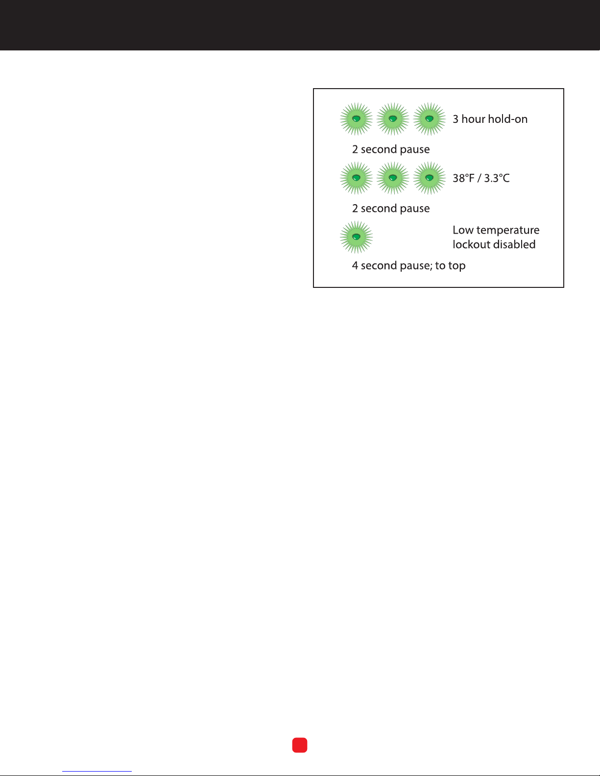
FIGURE 7. LED response, factory conguration
*factory setting value
TO ENTER THE CONFIGURATION PROCESS
• Hold the magnet to the switch for 3 seconds
• The green LED will go off
• Remove the magnet
• Process begins
The unit will ash the values of the three Field parameters
in order, repeatedly. The pattern begins with:
• Field 1’s green LED pulses
• 2 seconds between Field 1 and Field 2
• Field 2’s green LED pulses
• 2 seconds between Field 2 and Field 3
• Field 3’s LED pulses
• 4 seconds between Field 3 and returning to Field 1
After changing the parameters of any eld, the LCD-8
returns to the display mode.
CHANGE A FIELD’S PARAMETERS
To change a particular eld’s parameter: during the pulses
and the pause for that Field, SWIPE the magnet over the
switch the number of times equal to the number of pulses
identifying that parameter (refer to Table 1 on Page 7).
The green LED turns turn onand remains on until the
magnet is removed. That sets the value to 1. Positioning
the magnet on again, the LED turns on, then remove the
magnet: that
sets that value to 2. Continue in this fashion.
There are two (2) seconds between swipes. After 2
seconds, the LCD-8 maintains the entered value and
returns to display mode. If a value exceeds parameters,
the green LED ickers briey and returns to displaying the
previous values.
The four (4) second gap helps the user identify Field 1, the
starting point of the sequence, even after the sequences of
pulses have repeated several times. The LCD-8’s factoryset conguration is represented in Figure 7, above.
South Bend, Indiana USA | networketi.com
Note: if the magnet is held for 3 seconds during the
process of setting a value (having been released at least
once), the green LED ickers briey and restarts the
display process.
9
SNOW/ICE CONTROL INSTALLATION MANUAL | PART NO. 24782 REV C
Page 10

To Save the New Values
After changing parameters, hold the magnet over the
magnetic switch for 3 seconds. The green LED turns off
then ashes a brief message (3 short pulses and a long
pulse), and return to normal mode. This can be done even
if the parameters have not been changed.Post–Installation
LCD-8 Test.
3. Dry moisture sensing grid. Disconnect power to snow
melting system. Wait 1 minute, then reconnect power.
If system actuates, ensure sensing grid is dry and
ambient air temperature is above 38°F (3.3°C), then
repeat this step.
ORDERING INFORMATION
Most problems result from installation errors. Before
testing, verify that unit is properly installed.
1. Connect power to snow melting system. Wait 15
Order # Description
24619 LCD–8 Aerial Snow Controller
100–240 VAC (QTY 1)
seconds; system should not actuate.
24781 LCD–8, 24VAC
2. Using ice water or other cooling agent, cool ambient
air temperature sensor to below 38°F (3.3ºC); system
18703 Red Wire Nuts (QTY 4)
should not actuate. Apply moisture to moisture sensing
grid. System should actuate in less than 15 seconds.
24782 LCD–8 Manual (QTY 1)
SPECIFICATIONS
General
Area of use Nonhazardous locations
Approvals 109R, Type 873 Temperature Regulating Equipment
Enclosure
Protection NEMA 3R
Cover attachment Polycarbonate with machine screws
Entries 1 x 3/4” entry (bottom)
Material Polycarbonate
Mounting Pole mount
Dimensions 4.6” (W) x 6.1” (H) / 117mm (W) x 155mm (H)
Control
Supply voltage ETI PN 24619: 100VAC – 240VAC; 50/60 Hz, ETI PN 24781: 24VAC; 50/60 Hz
Load 3 amp maximum inductive, 16 amp maximum resistive
Heater Hold-On timer 0, 1, 3 (factory preset) or 5 hours; congured by magnetic reed switch
Set point temperature Off (moisture only), 36°F, 38°F (factory preset), 40°F; congured by magnetic reed switch
Interface
Status indicators SUPPLY (green): Power on; will ash while in conguration mode, HEAT (yellow): Heating cycle in progress
Wire and Cable Ratings
Power cable Size for heater load (16 amps maximum)
Heater cable Size for maximum heater load
Environmental
Operating temperature –40°F to 104°F (–40°C to 40°C)
Storage temperature −67°F to 167°F (−55°C to 75°C)
South Bend, Indiana USA | networketi.com
10
SNOW/ICE CONTROL INSTALLATION MANUAL | PART NO. 24782 REV C
Page 11

CONTACT CUSTOMER SERVICE
For assistance, contact Customer Service. Ofce hours are
from 8:00 AM until 5:00 PM ET.
Email: [email protected]
Web: networketi.com
Mail: ETI
1850 North Sheridan Street
South Bend, IN 46628
LIMITED WARRANTY
ETI’s two year limited warranty covering defects in
workmanship and materials applies. Contact Customer
Service for complete warranty information.
DISCLAIMER
ETI makes no representations or warranties, either
expressed or implied, with respect to the contents
of this publication or the products that it describes,
and specically disclaims any implied warranties of
merchantability or tness for any particular purpose. ETI
reserves the right to revise this publication, and to make
changes and improvements to the products described
in this publication, without the obligation of ETI to notify
any person or organization of such revisions, changes or
improvements.
Copyright © 2019 ETI,® All rights reserved.
South Bend, Indiana USA | networketi.com
11
SNOW/ICE CONTROL INSTALLATION MANUAL | PART NO. 24782 REV C
 Loading...