

Page 1
Model SIT®–6E Snow Switch
®
Part Number 20756
Installation Manual
We Manage Heat ®
Installation
Duct Seal
Sensor Housing
Take care in choosing a location for your pavement-
mounted sensor. The location should be:
• Centered between runs of hydronic tubing or heater
cable.
• Exposed to precipitation and pedestrian or vehicular
traf c.
• Away from external heat sources in excess of 185° F.
(85° C.).
The SIT–6E sensor can be located up to 2,000 feet (609.6
meters) from the associated system controls. Use 3-conductor
#18 AWG jacketed cable for distances up to 500 feet (152.4
meters). Use #12 AWG for greater lengths. Insulate and
waterproof all splices.
The sensor plate ships installed in the sensor housing.
Before installing the sensor housing remove the sensor plate,
placing the sensor plate and the three machine screws where
they will not be lost or damaged.
Install the sensor housing on a firm, smooth surface such
as a precast patio block or similar masonry module. Care
should be exercised in adjusting the final grade and level
of the sensor to ensure that the sensor surface will be flush
with the finished pavement, and that the adjacent pavement
be either level or slightly crowned. A sensor submerged in
puddled water will not function properly. To stabilize the final
location of the sensor prior to paving, insert lengths of reinforcing rod or similar dowels on opposite sides of the 3/4" (20 mm) rigid
conduit and secure with iron tie wire.
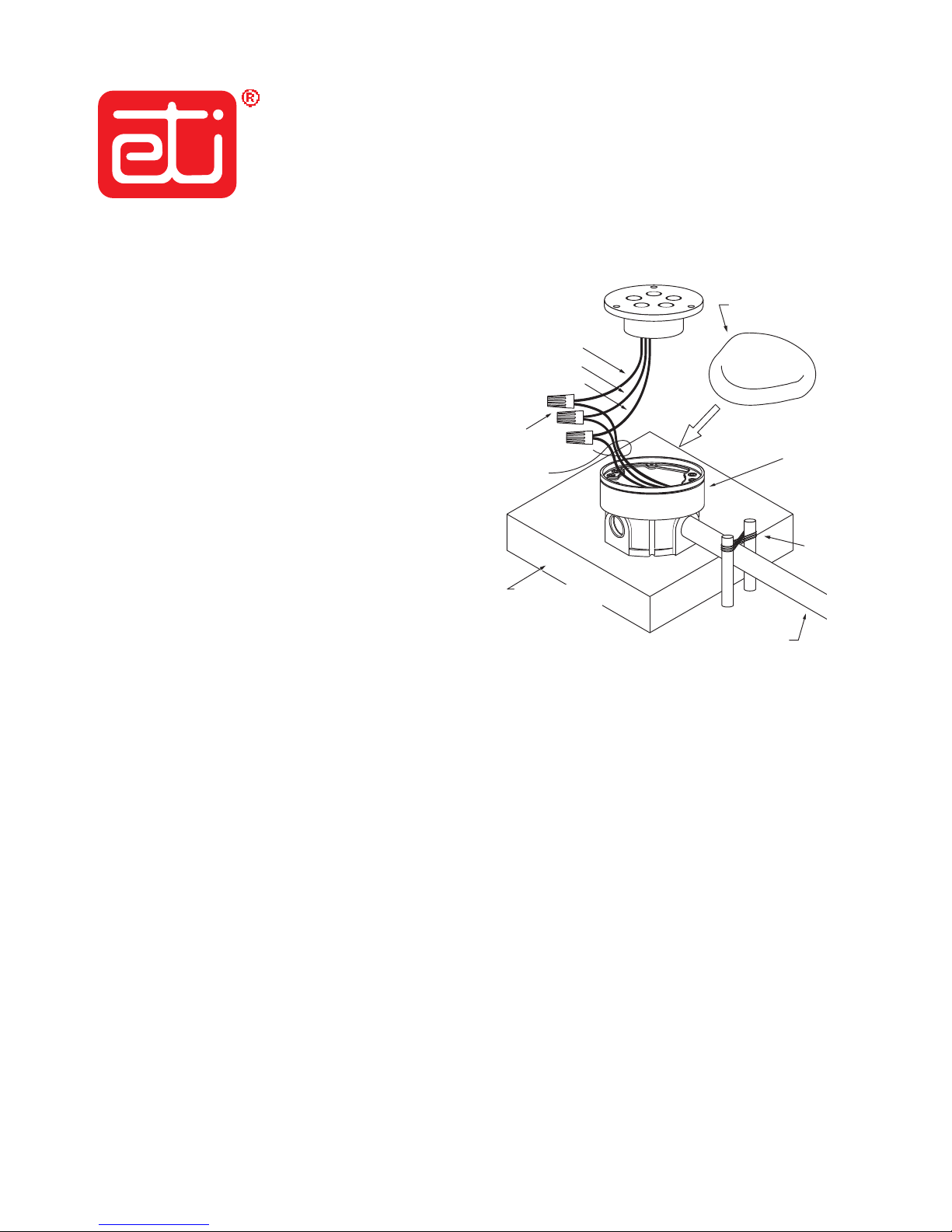
Use the sheet metal cover supplied with the SIT–6E to protect the sensor housing during paving. The sensor plate should
not be installed until after paving is complete and the sheet metal cover is removed. Caulking may be required between the sensor
housing and the paved surface.
Epoxy-filled
Wire Nut (3)
ETI P/N 20757
3-Conductor
Flat Cable
BLK (RETURN)
WHT (SIGNAL)
RED (POWER)
Precast Concrete
Patio Block or Similiar
Masonry Module
SIT–6E Installation Drawing
ETI P/N 20763
3/4" (20mm) Rigid Conduit
Enclosure
ETI P/N 20760
Secure Conduit
WIth Dowels and
Iron Tie WIre
Conduit
Use individual 3/4" (20 mm) rigid conduit for the entire installed length of the sensor cable, taking care to ensure that all embedded or
outdoor couplings and terminations are made watertight. Do not share conduit with other wiring. Do not route conduit across pavement
expansion or control joints. For sensors embedded in slab on grade, conduit should be depressed under these joints, as necessary.
Wiring
The SIT–6E sensor is furnished with 18"(46 cm) #18 AWG field leads. The red, black and white wires connect to the Control Panel
via user supplied cable. Use the epoxy filled wire nuts supplied. For proper wiring connections of the SIT–6E sensor to APS–3C,
APS–4C or EUR–5A controls consult the Installation Instructions for the appropriate Control Panel.
After wiring the sensor, kneed the supplied duct sealant till pliable. Pack duct sealant into the sensor housing leaving enough space
for the sensor electronics and wiring. Properly used, the duct sealant will minimize the accumulation of water and ice in the housing
and protect the sensor against possible ice damage.
Next, place wiring and electronics into the housing. Check for alignment between the sensor and pavement surfaces. If the sensor
and pavement are not aligned remove the sensor from the housing and adjust the housing flange. The housing flange can be raised up
to .63"(16 mm) to allow the sensor surface to be aligned with the pavement surface. A low sensor will pool water and not function
properly.
Page 2

Testing
Should paving material or other residue be adhered to the sensing elements, clean the surface with a Scotch™ Brite Pad. Do not
use metallic or course abrasives or detergents.
Thoroughly check the system before placing it in service. Our experience shows that installation errors cause the majority of
problems. Frequently encountered problems include wiring errors and improper waterproofing. Simple electrical tests and visual
inspections identify these problems.
Independent of weather conditions, the functional operation of an installed SIT–6E sensor may be determined using a digital
voltmeter (DVM) and a ten pound (4.54kg) bag of crushed ice, in the following manner:
Following this procedure may result in the engagement of the heater system. After completion, it is recommended to power
down the system to reset. If heater engagement can cause damage, it is up to the person on site to disconnect the heaters.
1. With the DVM set the 100 VAC range, verify the sensor supply voltage by connecting the negative (-) test lead to the sensor
black wire and the positive (+) test lead to the sensor red wire. A DVM reading between 22-28 VAC or 24-30 VDC is
acceptable. An AC component less than 28 VAC is allowed with a DC voltage in the proper range.
2. With the negative (-) test lead remaining in place, reconnect the positive (+) test lead to the sensor white wire and con rm
there is an identical voltage present.
3. Place the entire supply of crushed ice atop the sensor and allow a time lapse in excess of 20 minutes before observing
that no voltage is indicated by the DVM. (A nominal temperature below 38°F (1°C) must be detected before the sensor’s
normally-open contact is closed. If the sensor surface temperature was excessive prior to commencing this procedure, it will
be necessary to extend the cool down time interval by as much as an additional 20 minutes.)
4. With satisfactory results, disconnect the DVM and restore all sensor wiring connections.
You may elect to de-energize the snow/ice melting system heaters at the season’s end, however it is suggested the SIT–6E sensor’s
power supply be maintained continuously. The heat energy dissipated from the internal heater, although modest, will enhance the
long-term reliability of the SIT–6E sensor.
QUESTIONS AND COMMENTS
For technical help, questions or comments concerning this product or any of Environmental Technology, Inc. prod ucts contact
the Customer Service Department between 8:00am and 5:00pm EST at:
Voice: 800.234.4239 (USA and Canada) or 574.233.1202 (elsewhere)
Fax: 888.234.4238 (USA and Canada) or 574.233.2152 (elsewhere)
E-mail: [email protected]
DISCLAIMER
Environmental Technology, Inc. makes no representations or warranties, either expressed or implied, with respect to the contents of this publication
or the products that it describes, and speci cally disclaims any implied warranties of merchantability or tness for any particular purpose.
Environmental Technology, Inc. reserves the right to revise this publication and to make changes and improvements to the products described
in this publication without the obligation of Environmental Technology, Inc. to notify any person or organization of such revisions, changes or
improvements.
Copyright © 2008 Environmental Technology, Inc. All rights reserved. No part of this manual may be reproduced or translated in any form or by
any means, electronic or mechanical including photocopying and recording, for any purpose without the express written consent of Environmental
Technology, Inc.
Environmental Technology, Inc.
1850 N SheridanStreet
South Bend, Indiana 46628
(574) 233-1202 or (800) 234-4239
FAX (574) 233-2152 or (888) 234 4238
www.networketi.com
The ETI logo, Snow Switch, We Manage Heat, APS and SIT are reg istered trademarks of En vironmental Technology, Inc.
EUR is a trademark of En vironmental Tech nology, Inc.
Copyright © 2008 Environmental Technology, Inc. All rights reserved.
Printed in USA
PN20758 rev B 11/08
 Loading...