

Page 1
®
NETCOM
MODEL ASM-1
SMART MANIFOLD WITH AC POWER SUPPLY
PACKING LIST
QTY. PART NO. DESCRIPTION
1 23658 ASM–1 Smart Manifold, AC Power Supply
1 24303 Documentation CD ROM, ADH NETCOM and ASM–1 Smart Manifold
1 23681 ASM–1 Smart Manifold Installation Sheet (this document)
1 23678 ASM–1 Accessory Kit
2 18198 1/8" NPT to 1/4" Barbed Brass Fitting
2 23428 1/8" NPT to 3/8" Barbed Brass Fitting
4 23245 Mounting Bracket
1 17618 Power Cord
8 11040 Rack-mounting screw (#8-32)
8 10641 #8 Split Washer
CONNECTIONS
Ports are factory congured as: Port 1 – Input; Ports 3 and
4 – Outputs; Port 8 – Bleed Valve. Ports 2, 5, 6, and 7 are
factory congured as Unused. Settings may be changed,
but use these initially.
1. For the dehydrator, connect a 1/8” NPT to 3/8” tting
to Input Port 1 using Teon thread tape.
2. For the equipment lines, connect ttings as needed to
Output Ports 3 and 4 using Teon thread tape. Refer to
Instruction Manual for more information.
3. Connect required data and alarm relay ports. RS-422
and RS-232 ports may require conguration changes
via the web interface. See Instruction Manual for
more information.
South Bend, Indiana USA | networketi.com
4. Connect AC power cord. System can be connected
to 100 VAC – 240 VAC power without requiring any
conguration change.
5. Congure Smart Manifold as described on this
Installation Sheet, then shut off Manifold power.
6. Congure system dehydrator(s) as needed. Turn Smart
Manifold power back on.
ASM-1 INSTALLATION GUIDE | PART NO. 23681 REV A
Page 2

RACK MOUNTING
The Smart Manifold provides positions
for ush-mounting (for dual-post racks
and enclosures) or center-mounting
(for single-post racks).
If using mounting rails (not supplied),
do not install the mounting brackets.
WALL MOUNTING CONFIGURATION
To congure the dehydrator for wall
mount installation, remove the front
panel and the portion of the vented
cover with the ETI logo.
Reinstall the front panel so that it will
be in the new front position once
the dehydrator is positioned for wall
mounting. Reinstall the small vented
panel so that it will be in the new
bottom position.
WALL MOUNTING
Ensure the mounting surface and
hardware are suitable to support a
static load of approximately four times
the weight of the unit, or 44 pounds
(20 kg). Use four appropriate 5/16”
mounting hardware to fasten the unit
and ensure stable mounting. The
Smart Manifold is equipped with four
brackets for wall mounting.
South Bend, Indiana USA | networketi.com
2
ASM-1 INSTALLATION GUIDE | PART NO. 23681 REV A
Page 3
CONFIGURING THE SMART MANIFOLD SYSTEM
Consult your System Administrator or IT Department for
information regarding connecting to or communicating
with the Smart Manifold. The ASM – 1 Smart Manifold
Ethernet communications run at 10Base-T data rate and
half duplex. It is recommended that the network interface
to the ASM – 1 Smart Manifold is manually set to these
parameters and NOT to an autocongure mode.
Connect the ADH NETCOM dehydrator(s) and equipment
lines after conguration so the system does not go on
and off while conguring. Refer to the help screens.
Factory settings reect most installations and might
not be the best settings for your needs. Use the default
s’’ettings initially, then change settings as desired for your
own requirements.
set up by the IT administrator. The Netcom address will
need to be congured into the smart manifold so it can
monitor and control the dehydrator. Consult the user’s
manual for more details.
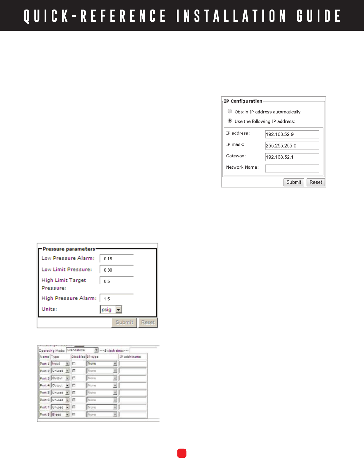
It should be noted that both the smart manifold and
Netcom have the same default IP address (192.168.52.9).
In order for them to work together they will each need to
be recongured to IP address’s that fall within the system
1. Using an Ethernet cable, connect to the Smart
Manifold from a PC. A cross-over cable or switch is
recommended. With a web browser, call up Smart
Manifold using the IP address 192.168.52.9.
2. From the Main Page, select Conguration.
3. Select Show/Change Port Info, then conrm settings.
See Instruction Manual for details.
4. Select Redundant, Parallel, or Standalone based on
screen prompts. With ADH NETCOM dehydrator(s),
use Redundant or Parallel. Press Submit to enter
the settings.
5. From the Conguration Page, select Pressure Limits
and conrm settings with your System Administrator.
Change settings if desired, then press Submit.
6. On the IP/Serial Information page, set IP address or
network name. Obtain Mask and Gateway settings
from System Administrator. Note settings, then shut
off Smart Manifold.
South Bend, Indiana USA | networketi.com
SYSTEM SET-UP
1. Connect equipment lines to Smart Manifold, then
dehydrator(s). See Connections section. Leave power
switches OFF and plug each device into surgeprotecting power strips.
3
ASM-1 INSTALLATION GUIDE | PART NO. 23681 REV A
Page 4

2. Connect to the dehydrator(s) and change dehydrator
IP address(es) as needed. Perform Reset Procedure
as described in Instruction Manual if needed and
change dehydrator IP address to 192.168.52.9, then
complete conguration. Congure each dehydrator
as entered on Smart Manifold Port Info page.
LIMITED WARRANTY
ETI’s two year limited warranty covering defects in
workmanship and materials applies. Contact Customer
Service for complete warranty information.
3. Following conguration of each dehydrator, turn Smart
Manifold power back on and begin system operation.
Contacting Customer Service
For technical help, questions or comments concerning
this product or any ETI product contact Customer Service
8:00 a.m. - 5:00 p.m. EST.
Email: [email protected]
Web: networketi.com
Mail: ETI
1850 North Sheridan Street
South Bend, IN 46628
DISCLAIMER
ETI makes no representations or warranties, either
expressed or implied, with respect to the contents
of this publication or the products that it describes,
and specically disclaims any implied warranties of
merchantability or tness for any particular purpose. ETI
reserves the right to revise this publication, and to make
changes and improvements to the products described
in this publication, without the obligation of ETI to notify
any person or organization of such revisions, changes or
improvements.
Copyright © 2019 ETI,® All rights reserved.
South Bend, Indiana USA | networketi.com
4
ASM-1 INSTALLATION GUIDE | PART NO. 23681 REV A
 Loading...