

Page 1
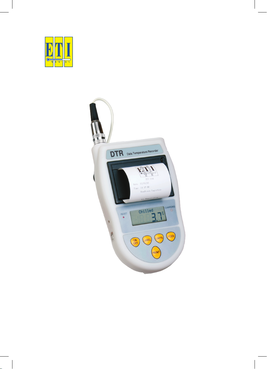
DTR
printing thermometer
User Manual
order code: 226-270
Page 2

2
Page 3

CONTENTS
Introduction 4
DTR overview 4
probes 5
functions 5
display 5
DTR operation 6
switching the DTR on or off 6
changing label 6
displaying limits 6
feeding paper 6
printing a ticket 6
remote button operation 6
batteries 7
recharging the DTR 7
connecting devise to PC 7
reset 7
cleaning 7
paper loading procedure 8-9
specification 10
3
Page 4

INTRODUCTION
The DTR (Data Temperature Recorder) is a hand held temperature
measuring device that prints and saves temperature readings.
The DTR measures temperature across the range of -39.9 °C/-39.8 °F
to 149.9 °C/301.8 °F, with a 0.1 °C resolution.
When the DTR is fully charged, up to 500 prints can be achieved. Up
to 2500 readings can be stored in memory.
PROBES
The DTR can be used with the standard range of ETI thermistor probes
or the DTR switch penetration probe. The switch penetration probe has
a button (remote button) on the top of the handle. Pressing the probe
button results in a print operation with a pre-defined number of copies
(see remote button operation). The probe is connected via the Lumberg
socket at the top of the instrument.
FUNCTIONS
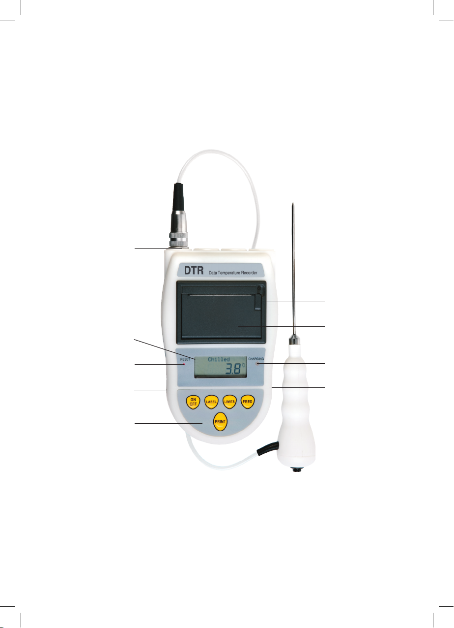
The DTR control panel consists of five buttons:
ON/OFF - Switches the DTR On/Off.
LABEL - Changes selected label.
LIMITS - Displays High or Low Limit.
FEED - Feeds the paper.
PRINT - Takes a reading, prints a ticket and stores the reading,
date and time in memory.
DISPLAY
The display consists of a 12 character alphanumeric section and a four
and a half digit temperature section. Low battery indication is shown
by 'Lo Bat'.
4
Page 5
probe socket
LCD
DTR OVERVIEW
cover handle
printer cover
'reset' button
USB socket
control panel
charge indicator
power socket
5
Page 6

DTR OPERATION
SWITCHING THE DTR ON OR OFF
The 'On/Off' button switches the DTR on or off. 'Switch off' will be
displayed for two seconds before shut down is complete.
CHANGING LABEL
To scroll through the stored labels, press the 'Label' button. The selected
label will be displayed on the screen. Labels change in a continuous
loop. Up to four labels can be stored using the PC software.
DISPLAYING LIMITS
To display the high or low limit for the selected label, press the 'Limits'
button. When the high or low limit is selected the temperature value
displayed represents the corresponding limit and the name of the label
alternates with 'High Limit:' or 'Low Limit:' respectively.
FEEDING PAPER
Press the Feed button to feed the paper. If there is no paper loaded or
the printer cover is open, 'Paper out' text will be displayed for five seconds.
PRINTING A TICKET
To print a ticket, press the 'Print' button. A temperature measurement
will be taken and a ticket containing the current temperature value will
be printed. If there is no paper loaded or printer cover is open, 'Paper
out' will be displayed for five seconds, but the reading will still be stored.
It can be retrieved later using the DTR PC software.
After a ticket has been printed, the display will show 'Copy' for five
seconds. Pressing the 'Print' button during this time prints a copy of the
last ticket.
REMOTE BUTTON OPERATION
Pressing the button on the DTR switch probe (remote button) performs
a similar function to pressing the 'Print' button. The only difference is
that the printing delay time and number of copies defined in the PC
software will take effect.
6
Page 7

BATTERIES
The DTR is fitted with a 3 cell rechargeable 3.6V NiMh battery pack. It is
NOT user replaceable. Please return to the ETI Service Department for
battery replacement. When the DTR power is low, the 'Lo Bat' segment
of the LCD is lit. Print and feed operations are inhibited when 'Lo Bat'
is indicated. Pressing the 'Print' or 'Feed' buttons will result in 'Recharge'
being displayed for a short time in the display.
RECHARGING THE DTR
To recharge the DTR remove the rubber cap and plug the power cable
into the socket on the right of the instrument. A flashing 'Charging' LED
indicates that the device is being charged.
A slow flashing LED (once/second) indicates normal charging. A fast
flash rate (four times/second) indicates a charging fault (probably the
batteries are too cold to charge). The DTR should only be recharged
in an ambient temperature between 5 and 40 °C.
Charge only with an ETI DTR power supply - 12V, 3.3A (40Watt).
!
Damage may occur if other power supplies are used.
CONNECTING DEVICE TO THE PC
To connect the DTR to a PC remove the rubber cap and plug the USB
cable into the socket on the left side of the instrument. Use DTR PC
software to customise DTR settings and ticket layout and to download
stored reading.
RESET
If the DTR fails to respond, press the 'reset' button on the front of the
instrument which is situated to the left of the display.
CLEANING
Clean only the outside of the instrument with a damp cloth or antibacterial wipe.
7
Page 8

PAPER LOADING PROCEDURE
To reload the printer with a new paper roll, follow the steps below:
1. Un-clip the printer cover handle (fig 1).
2. Pull the printer cover handle until the cover un-clips. To avoid
damage to the handle do not use excessive force (Fig 2).
3. Lift the lid until completely open (fig 3).
4. Remove any existing paper or the plastic tube from the previous
roll. The easiest way to do that is to turn the DTR upside down,
so the printer contents fall out (fig 4).
5. Prepare a new paper roll – remove the outer packaging and the
holding sticker. Place into printer as shown in Fig 5. The glossy
side of the paper should be against the printing mechanism
6. Push the paper fully into the printer housing (fig 6).
7. Close the lid, leaving a short strip of the paper roll protruding
from the printer (fig 7).
8. Lock the cover by pressing shut. Push the printer cover handle
shut (fig 8).
8
Page 9
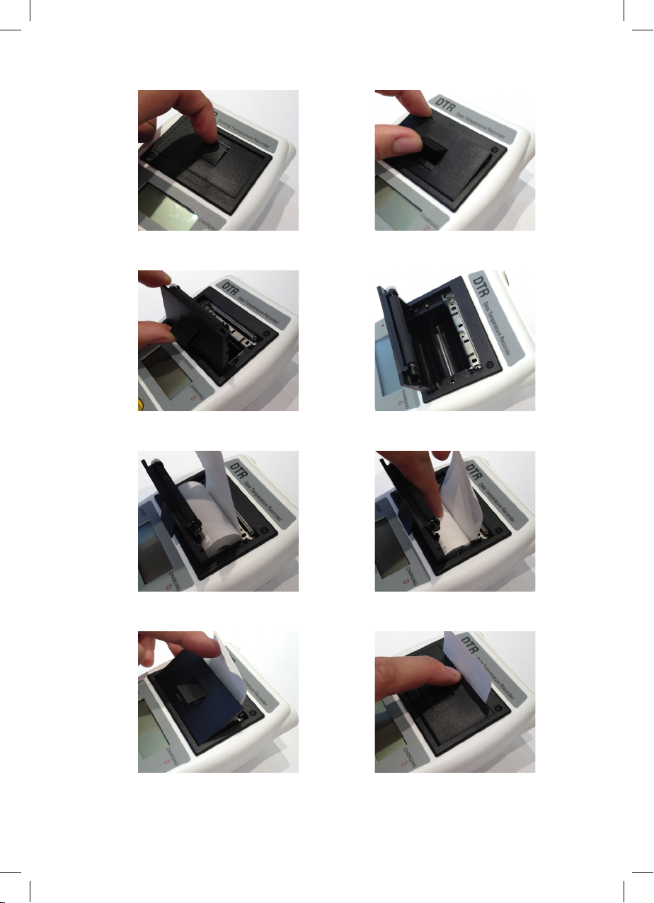
fig 1
fig 2
fig 3
fig 5
fig 4
fig 6
fig 7 fig 8
9
Page 10

SPECIFICATION
range -39.9 to 149.9 °C (-39.8 to 301.8 °F)
operating temp range 5 to 50 °C & 10 to 80 %rh
resolution 0.1 °C/°F
accuracy ±0.5 °C
battery Ni-MH 3.6V
battery life approximately 500 prints from a full charge
battery charging temp range 5 to 40 °C
battery charging cycles >500
charging power supply INPUT 100-240V - 47-63Hz 1-1A Max
OUTPUT 12V, 3.3A (40Watt)
sensor type thermistor
connector type 6 pin Lumberg
printer type thermal
paper width 57 mm
paper roll diameter Ø30 mm maximum
print lines per roll 2000 approx. (Ø30 mm roll)
display 12.7 mm LCD & 12 character
alphanumeric
dimensions 54 x 110 x 183 mm
weight 630 grams
IP rating IP2X
If the equipment is used in a manner not specified by the manufacturer,
the protection provided by the equipment may be impaired.
10
Page 11

NOTES
11
Page 12

PLEASE NOTE: Due to regular software updates, please visit the
download page on our website etiltd.com/downloads to ensure you
have the latest version.
manufactured by
Electronic Temperature Instruments Ltd
Easting Close, Worthing, West Sussex BN14 8HQ
tel: 01903 202151 · fax: 01903 202445
email: [email protected] · www.etiltd.com
226-270/21.11.14
 Loading...