

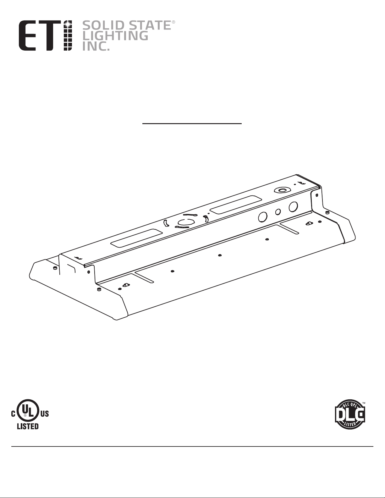
USE AND CARE GUIDE
2 FT. LINEAR HIGH BAY LED LIGHT
Part # HB-171-850-MV-D
Model # 50232162
Questions, problems, missing parts?
Call ETiSSL Customer Service
8 a.m. - 5 p.m., CST, Monday - Friday
1-855-ETI-SSLI (1-855-384-7754)
www.ETiSSL.com
THANK YOU
We appreciate the trust and confidence you have placed in ETi through the purchase of this LED light.
Visit us online to see our full line of products. Thank you for choosing ETi!
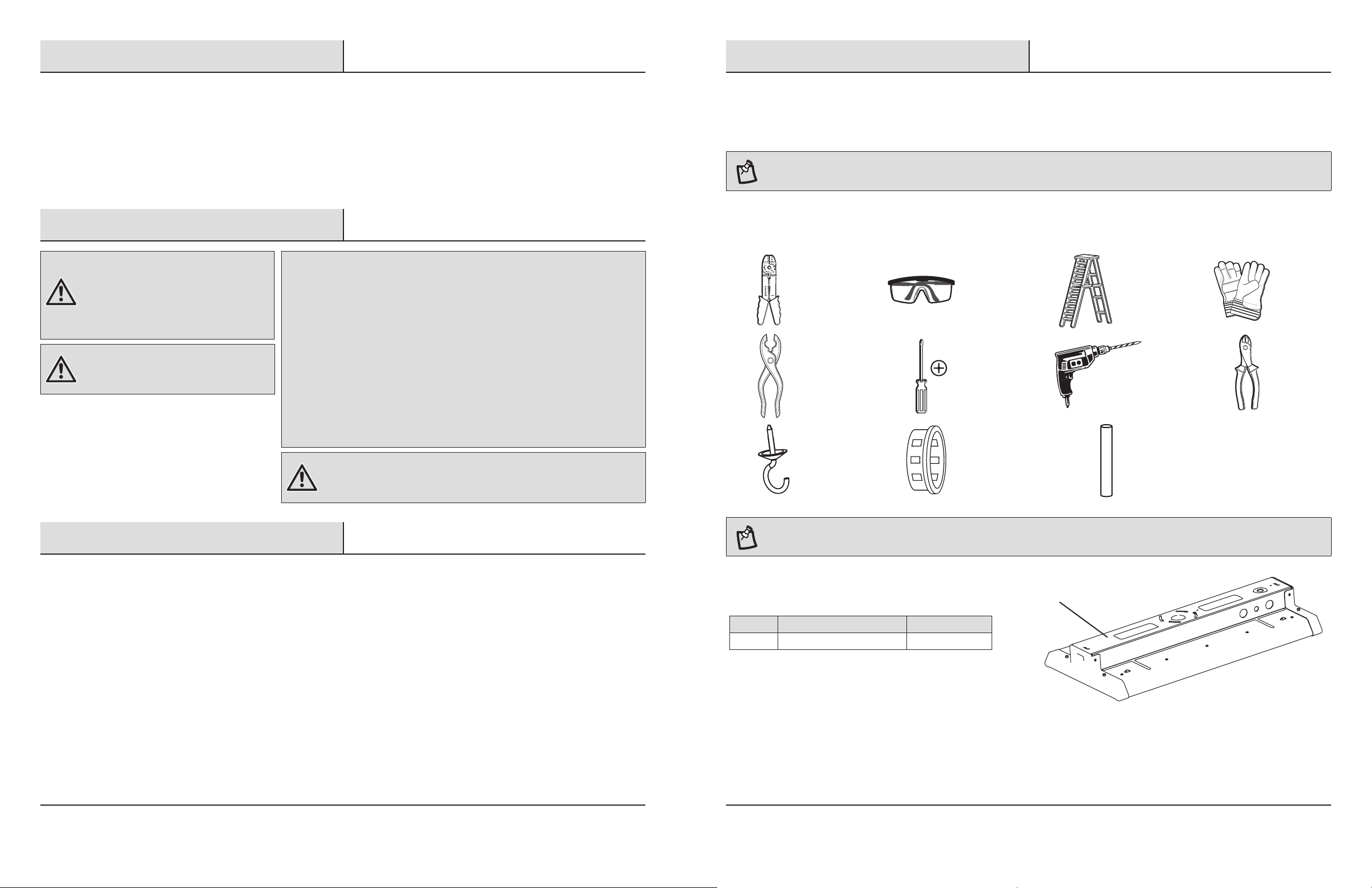
Table of Contents
Pre-Installation
Table of Contents ...................................2
Safety Information ..................................2
Warranty ..........................................2
Pre-Installation .....................................3
Planning Installation ...............................3
Tools Required ....................................3
Package Contents .................................4
Hardware Included .................................4
Safety Information
WARNING: Carefully read and understand
the information given in this manual before
beginning the assembly and installation.
Failure to do so could lead to electric shock,
fire, or other injuries which could be hazardous
or even fatal.
WARNING: Ensure the electricity to the wires
you are working on is shut off. Either remove
the fuse or turn off the circuit breaker.
NOTICE: This equipment has been tested and found to comply with the limits for a
Class B digital device, pursuant to Part 15B of the FCC Rules. These limits are designed to
provide reasonable protection against harmful interference in a residential installation.
This equipment generates, uses and can radiate radio frequency energy and, if not installed
and used in accordance with the instructions, may cause harmful interference to radio
communications.
However, there is no guarantee that interference will not occur in a particular installation. If
this equipment does cause harmful interference to radio or television reception, which can
be determined by turning the equipment off and on, the user is encouraged to try to correct
the interference by one or more of the following measures:
□ Reorient or relocate the receiving antenna.
□ Increase the separation between the equipment and the receiver.
□ Connect the equipment into an outlet on a circuit different from that to which the
receiver is connected.
□ Consult the dealer or an experienced radio/TV technician for help.
Installation ........................................4
Suspension Mounting ..............................4
Surface Mounting .................................7
Downrod Mounting ...............................11
Care and Cleaning .................................14
Troubleshooting ...................................14
WARNING: Changes or modifications not expressly approved by the party
responsible for compliance could void the user’s authority to operate the
equipment.
PLANNING INSTALLATION
Before beginning assembly, installation or operation of product, make sure all parts are present. Compare parts with the package
contents list. If any part is missing or damaged, do not attempt to assemble, install or operate the product. Contact customer service for
replacement parts.
NOTE: Keep your receipt and these instructions for proof of purchase.
If you are unfamiliar with electrical installations, we recommend you contact a qualified electrician to do the installation.
TOOLS REQUIRED
Wire
Strippers
Pliers
Hook
Screws*
Safety
Goggles
Phillips
Screwdriver
1/2 in. Snap-in
Bushing*
Ladder Gloves
Power Drill
with Drill Bits
Rigid Pipe**
* For Suspension
Mounting only
** For Downrod
Mounting only
Wire
Cutters
Warranty
This product is warranted for a period of 5 years from the date of original purchase against defects in materials and
workmanship. If this product should fail to operate due to defects in material or workmanship within 60 months of purchase,
see www.ETiSSL.com for details. This product will be repaired or replaced, at ETi’s option. This warranty is expressly
limited to repair or replacement of product and liability for direct, incidental, or consequential damages is hereby expressly
excluded. Some states do not allow exclusions of direct, incidental or consequential damages, so the above limitation of
exclusion may not apply to you. This warranty gives the consumer specific legal rights, which vary from state to state.
WARRANTY IS VOID IF PRODUCT IS NOT USED FOR THE PURPOSE WHICH THIS PRODUCT IS MANUFACTURED.
2
NOTE: Eye hooks can be used as an alternate method of attaching the fixture to the ceiling when suspension mounting.
PACKAGE CONTENTS
Part Description Quantity
A Fixture Body 1
3 ETiSSL.com
Please contact 1-855-384-7754 for further assistance.
A
Pre-Installation (continued)
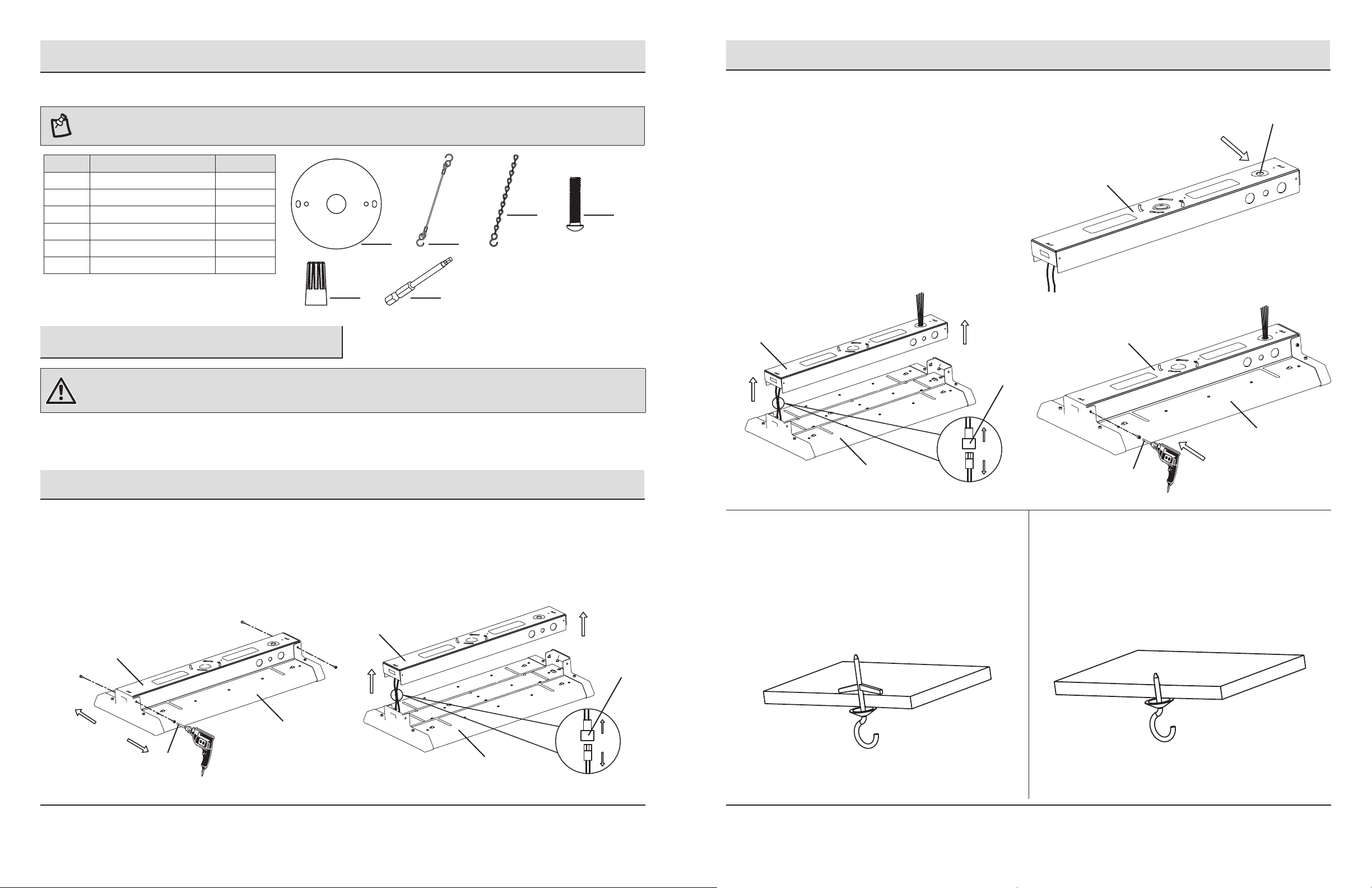
HARDWARE INCLUDED
NOTE: Hardware not shown to actual size.
Part Description Quantity
AA Cover Plate 1
BB Cable Set 2
CC Chain with S-Hook 2
DD Electrical Box Screw 2
EE Wire Connector 3
FF Power Tool Hex Bit 1
AA
EE FF
BB
CC
DD
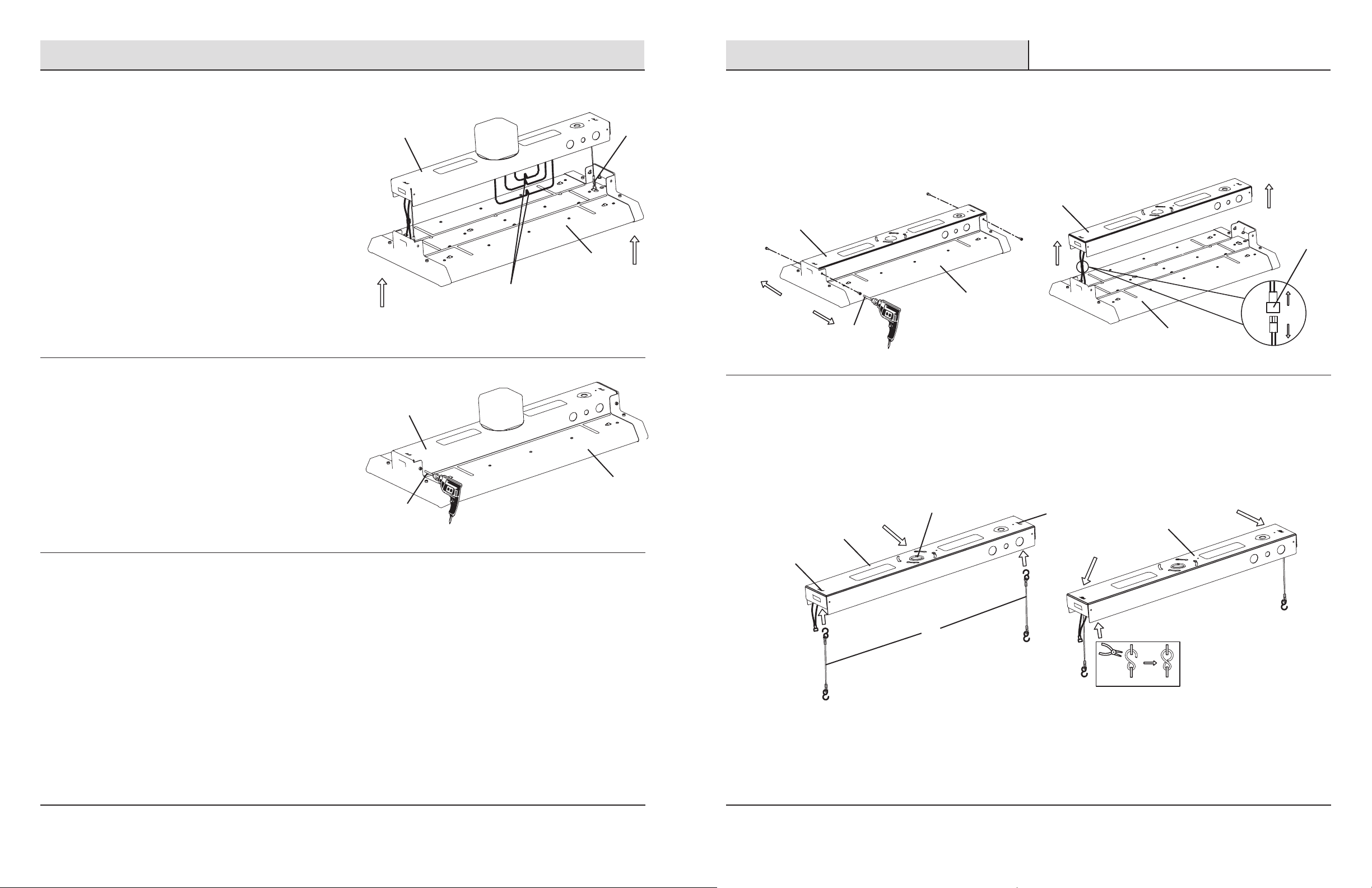
Suspension Mounting (continued)
Preparing the power supply box for wiring
2
□ Remove the knock-out near the end of the power supply box.
□ Fit a 1/2 in. snap-in bushing into the knock-out hole.
□ Feed the wiring out through the bushing and knock-out hole.
□ Reconnect the two ends of the Quick Connect wires.
□ Align the screw holes in the fixture body (A) with the screw holes
in the power supply box.
□ Fasten the fixture body (A) to the power supply
box with the previously removed screws, using the
power tool hex bit (FF).
Knock-out Hole
Power Supply Box
Installation
WARNING: RISK OF ELECTRIC SHOCK. Ensure the electricity to the wires you are working on is shut off. Either remove the fuse or turn off the
circuit breaker before removing the existing light fixture or installing the new one.
With power disconnected to the electrical box, remove the existing fixture. Make a sketch of how the current fixture is wired (by wire color)
or mark the wires with masking tape and a pencil so you will know how to properly reconnect the wires to the new LED light fixture.
Suspension Mounting
Removing the power supply box
1
□ Remove the four screws that attach the power supply box to the LED fixture body (A) using the power tool hex bit (FF).
□ Put the screws aside as they will be needed to reattach the power supply box to the fixture body (A) in a later step.
□ Lift the power supply box from the fixture body (A) and unplug the Quick Connect wires.
Power Supply Box
Power Supply Box
Quick
Connect
Power Supply Box
A
Mounting to drywall
3
□ Drill two holes large enough to clear the closed flaps of the
butterfly nut on the toggle bolt (not included).
□ Fasten the toggle bolt into the butterfly nut before
inserting the flaps into the ceiling.
□ Tighten the toggle bolt.
Quick
Connect
Power Supply Box
A
FF
Mounting to wood
4
□ Drill two 1/16 in. diameter holes in the ceiling to
accommodate hook screws (not included).
□ Fasten the combo wood-machine end into the metal hook.
□ Tighten the hook screw (not included) into the wood.
A
FF
4
A
5 ETiSSL.com
Please contact 1-855-384-7754 for further assistance.

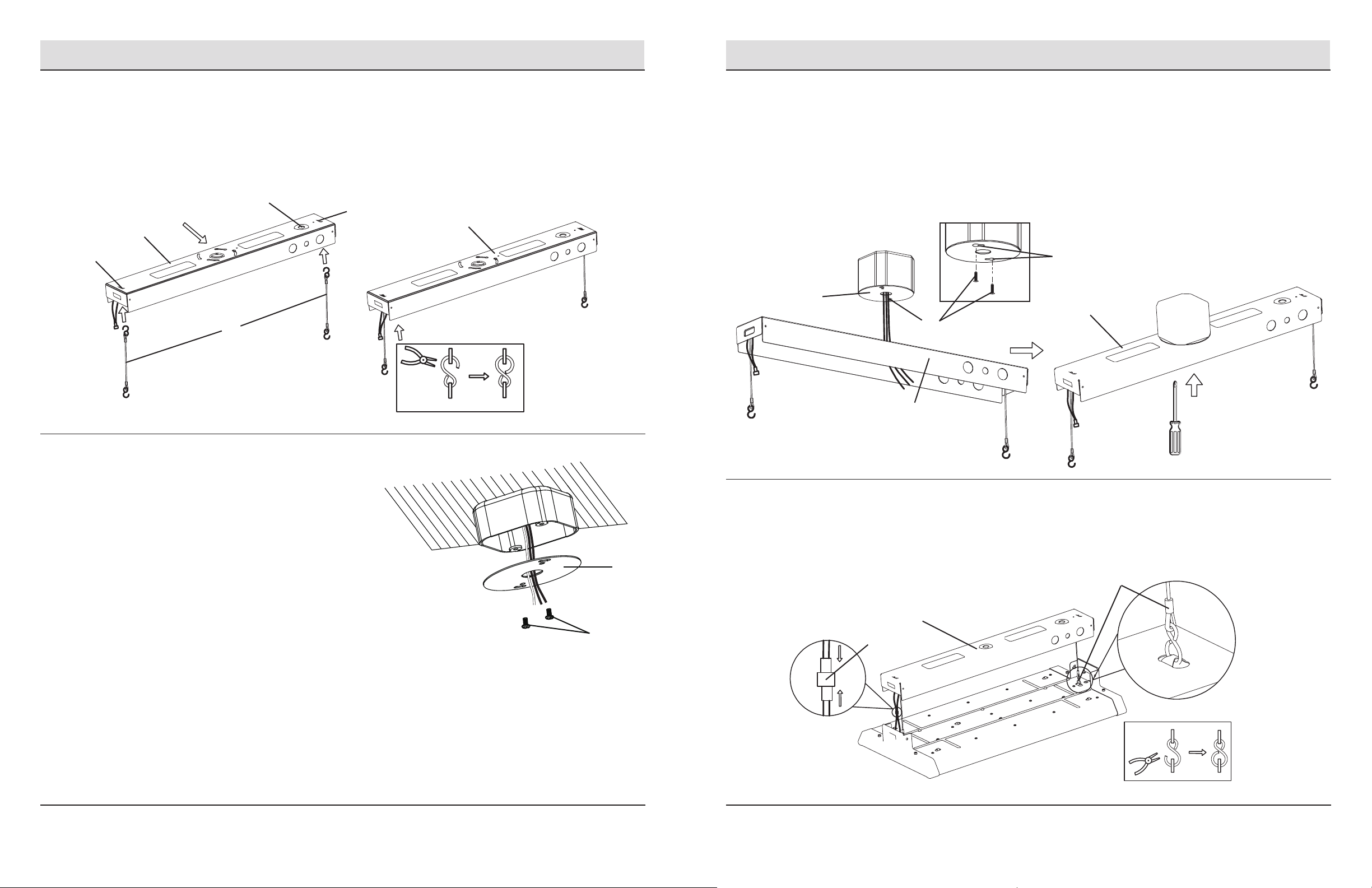
Suspension Mounting (continued) Suspension Mounting (continued)
Preparing the fixture body for mounting
5
□ Attach the hook on one end of the cable set (BB) to a hanging hole on the fixture body (A) and close the hook with pliers to
secure it.
□ Attach the hook on the other end of the cable set (BB) to the other hanging hole on the same end of the fixture body (A) and
close the hook with pliers to secure it.
□ Attach the S-hook on one end of the mounting chain (CC) to the center of the cable set (BB) and
close the hook with pliers to secure it.
□ Repeat these steps with the second cable set (BB) and mounting chain (CC) on the
opposite end of the fixture body (A).
CC
BB
CC
BB
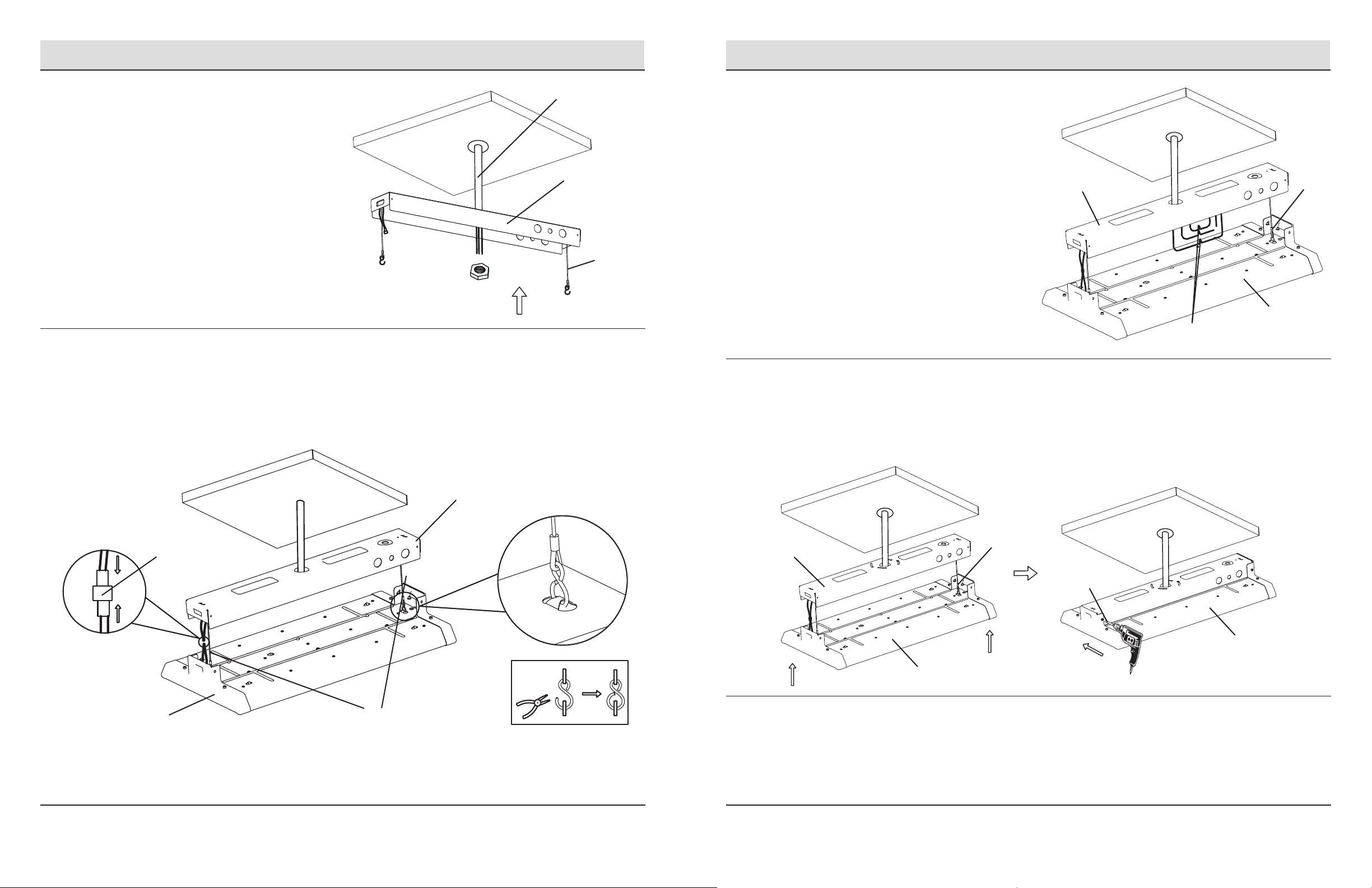
Making the electrical connections
7
□ Feed the electrical wires from the fixture (A) through the cover plate (AA).
□ Connect the hot and neutral (black and white) wires from the fixture body
(A) to the same color wires from the electrical box.
□ Connect the green wire from the fixture body (A) to the grounding wire from
the electrical box.
□ If 0-10v dimming circuit is available, connect the purple and gray wires
from the power supply box to the same color wires from the electrical box.
□ If dimming is not desired, wrap the ends of the purple and gray wires with electrical
tape to cover the wire.
□ Cover the wire connections using the wire connectors (EE).
□ Wrap the wire connectors (EE) with electrical tape for a more secure connection.
□ Position the wires back inside the electrical box and attach the cover plate (AA) to the
electrical box using the electrical box screws (DD).
Restoring power
8
A
□ Restore power at the electrical panel.
□ Turn on the light switch to activate the fixture.
AA
DD
Attaching the chain to the ceiling
6
□ Hang the fixture body by placing one chain (CC) over each hook (not included) that has been installed on the ceiling.
□ Adjust the chains to level the light. The fixture must hang at least 3 in. from the ceiling.
□ Feed the wiring through an appropriate conduit based on local electrical code.
CAUTION: Check local electrical code to determine the appropriate type of conduit for the wiring. Do not leave the wiring exposed.
CC
BB
A
A
CC
Surface Mounting
Removing the power supply box
1
□ Remove the four screws that attach the power supply box to the LED fixture body (A) using the power tool hex bit (FF).
□ Put the screws aside as they will be needed to reattach the power supply box to the fixture body (A) in a later step.
□ Lift the power supply box from the fixture body (A) and unplug the Quick Connect wires.
Power Supply Box
Power Supply Box
A
FF
A
Quick
Connect
6
7 ETiSSL.com
Please contact 1-855-384-7754 for further assistance.
Surface Mounting (continued)
Surface Mounting (continued)
Preparing the power supply box for mounting
2
□ Remove the knock-out near the end of the power supply box.
□ Attach one hook from each of the two cable sets (BB) to the hanging holes on the power supply box.
□ Close the open hooks attached to the power supply box with pliers. Do not close the open S-hooks at the bottoms of the
cable sets.
Knock-out
Hole
Power Supply Box
Hanging Holes
BB
Hanging
Holes
Power Supply Box
Mounting the power supply box
4
□ Pull the electrical wires from the electrical box through the knock-out hole in the power supply box.
□ Align the large ends of the keyholes in the power supply box with the mounting screws (DD), allowing the heads of the screws
(DD) to come through the large ends of the keyholes.
□ Rotate the power supply box until the heads of the mounting screws (DD) slide into the narrow ends of the keyholes.
□ Tighten the mounting screws (DD) to secure the power supply box to the cover plate (AA) and electrical box.
Keyholes
AA
DD
Power Supply Box
Power Supply Box
Attaching the cover plate
3
□ Feed the electrical wires from the electrical box through the cover
plate (AA).
□ Secure the cover plate (AA) to the electrical box with the electrical
box screws (DD), but do not tighten them fully. Screw them into
the cover plate (AA) until there is about 3/8 in. between the cover
plate (AA) and the underside of the screw head.
DD
AA
Attaching the fixture body to the power supply box
5
□ Attach the open hooks on the ends of the cable sets (BB) to the hanging holes on the fixture body (A).
□ Close the hook openings with pliers.
□ Connect the two ends of the Quick Connect wires.
A
Quick
Connect
BB
8
9 ETiSSL.com
Please contact 1-855-384-7754 for further assistance.
Surface Mounting (continued)
Downrod Mounting
Making the electrical connections
6
□ Connect the hot and neutral (black and white) wires from
the power supply box to the same color wires from the
electrical box.
□ Connect the green wire from the power supply box to the
grounding wire from the electrical box.
□ If 0-10v dimming circuit is available, connect the purple and
gray wires from the power supply box to the same color
wires from the electrical box.
□ If dimming is not desired, wrap the ends of the purple and
gray wires with electrical tape to cover the wire.
□ Cover the wire connections using the wire connectors (EE).
□ Wrap the wire connectors (EE) with electrical tape for a
more secure connection.
Reattaching the fixture body to
7
the power supply box
□ Position the wires back inside the power supply box.
□ Align the screw holes in the fixture body (A) with the
screw holes in the power supply box, making sure all
wiring is thoroughly tucked inside the power supply box.
□ Fasten the fixture body (A) to the power supply box with
the previously removed screws, using the power tool hex
bit (FF).
Power Supply Box
Power Supply Box
FF
EE
Removing the power supply box
1
BB
A
A
□ Remove the four screws that attach the power supply box to the LED fixture body (A) using the power tool hex bit (FF).
□ Put the screws aside as they will be needed to reattach the power supply box to the fixture body (A) in a later step.
□ Lift the power supply box from the fixture body (A) and unplug the Quick Connect wires.
Power Supply Box
Power Supply Box
A
FF
Preparing the power supply box for mounting
2
□ Remove the center knock-out on the power supply box.
□ Attach one hook from each of the two cable sets (BB) to the hanging holes on the power supply box.
□ Close the open hooks attached to the power supply box with pliers. Do not close the open S hooks at the bottoms of the
cable sets.
Center Knock-out Hole
Power Supply Box
Hanging
Holes
Power Supply Box
A
Quick
Connect
Restoring power
8
□ Restore power at the electrical panel.
□ Turn on the light switch to activate the fixture.
10
Hanging Holes
BB
11 ETiSSL.com
Please contact 1-855-384-7754 for further assistance.
Downrod Mounting (continued)
Downrod Mounting (continued)
Mounting the power supply box
3
□ Attach the rigid pipe (not included) to the ceiling and pull
the wiring from the electrical box through the pipe.
□ Place the pipe through the center knock-out hole in the
power supply box and secure it with the appropriately
sized hardware (not included).
Attaching the fixture body to the power supply box
4
□ Attach the open hooks on the ends of the cable sets (BB) to the hanging holes on the fixture body (A).
□ Close the hook openings with pliers.
□ Connect the two ends of the Quick Connect wires.
Rigid Pipe
Power Supply
Box
BB
Making the electrical connections
5
□ Connect the hot and neutral (black and white) wires from
the power supply box to the same color wires from the
electrical box.
□ Connect the green wire from the power supply box to the
grounding wire from the electrical box.
□ If 0-10v dimming circuit is available, connect the purple
and gray wires from the power supply box to the same
color wires from the electrical box.
□ If dimming is not desired, wrap the ends of the purple and
gray wires with electrical tape to cover the wire.
□ Cover the wire connections using the wire connectors (EE).
□ Wrap the wire connectors (EE) with electrical tape for a
more secure connection.
□ Position the wires back inside the power supply box.
Reattaching the power supply box to the fixture body
6
□ Align the screw holes in the fixture body (A) with the screw holes in the power supply box, making sure all wiring is thoroughly
tucked inside the power supply box.
□ Fasten the fixture body (A) to the power supply box with the previously removed screws, using the power tool hex bit (FF).
Power Supply Box
EE
BB
A
Quick
Connect
A
12
BB
Power
Supply Box
Power Supply Box
A
Restoring power
7
□ Restore power at the electrical panel.
□ Turn on the light switch to activate the fixture.
13 ETiSSL.com
Please contact 1-855-384-7754 for further assistance.
BB
FF
A
Care and Cleaning
CAUTION: Before attempting to clean fixture, disconnect the power to the fixture by turning the breaker off or removing the fuse from
the fuse box.
□ Clean the fixture with a soft, dry cloth.
□ Do not use cleaners with chemicals, solvents, or harsh abrasives.
□ Do not use liquid cleaner on the LEDs, LED driver, or wiring inside the light fixture.
Troubleshooting
WARNING: Before doing any work on the fixture, disconnect power to the light fixture.
Minor problems often can be fixed without the help of an electrician.
Problem Possible Cause Solution
The fixture will not light. The power is off. Ensure the power supply is on.
The circuit breaker is off. Ensure the circuit breaker is in the on position.
There is a bad connection. Check to ensure proper wire connections are made.
Contact a qualified electrician.
There is a defective switch. Contact a qualified electrician.
The fuse blows or the circuit breaker
trips when the light is turned on.
The wires are crossed or the power
wire is grounding out.
Check the wire connections.
Contact a qualified electrician or call Commercial
Electric customer service 1-877-527-0313.
Notes
14
15 ETiSSL.com
Please contact 1-855-384-7754 for further assistance.

Partie # HB-171-850-MV-D
Modèle n° 50232162
GUIDE D’UTILISATION ET D’ENTRETIEN
LAMPE LINÉAIRE À DEL DE 61 CM POUR PLAFOND ÉLEVÉ
Questions, problems, missing parts?
Call ETiSSL Customer Service
8 a.m. - 5 p.m., CST, Monday - Friday
1-855-ETI-SSLI (1-855-384-7754)
www.ETiSSL.com
Retain this manual for future use.
16
Questions, difficultés, pièces manquantes?
Téléphonez au service à la clientèle de ETiSSL
8 h - 17 h, HNC, du lundi au vendredi.
1-855-ETI-SSLI (1-855-384-7754)
www.ETiSSL.com
MERCI
Nous apprécions la confiance que vous avez accordé à la ETi en achetant ce luminaire à DEL.
Consultez notre gamme complète de produits. Nous vous remercions d’avoir choisi ETi!

Table des matières
Avant l’installation
Table des matières .................................18
Consignes de sécurité ..............................18
Garantie ..........................................18
Avant l’installation .................................18
Planification de l’installation ........................18
Outils requis .....................................18
Contenu de l’emballage ............................18
Quincaillerie fournie ...............................19
Consignes de sécurité
AVERTISSEMENT : Lisez et comprenez
bien les renseignements fournis dans ce
manuel avant de procéder à l’assemblage
et à l’installation. Un manque à le faire
pourrait mener à un risque de choc électrique,
d’incendie ou de blessures qui pourraient être
graves, voire même mortelles.
AVERTISSEMENT : Assurez-vous de
couper le courant au circuit sur lequel vous
travaillerez. Enlevez le fusible ou coupez le
disjoncteur.
AVIS : Ce dispositif a été testé et se trouve en deça des limites pour un dispositif
numérique de Classe B aux termes de la section 15B des règlements de la FCC. Ces
limites servent à offrir une protection raisonnable contre une interference nocive dans une
installation résidentielle.
Ce dispositif génère, utilise et peut irradier une énergie de fréquence radio; s’il n’est pas
installé et utilisé conformément aux directives, il peut causer une interférence nocive aux
communications radio. Il n’est toutefois pas garanti qu’aucune interférence ne surviendra
dans une installation particulière. Si le dispositif cause une interférence nuisible à la
réception radio ou télé, ce qui peut être établi en éteignant et rallumant le dispositif, on
conseille à l’utilisateur de tenter de remédier à la situation en utilisant une ou plusieurs de
ces procédures :
□ Réorienter ou déplacer l’antenne réceptrice.
□ Augmenter la distance entre le dispositif et le poste récepteur.
□ Brancher l’équipement dans une prise de courant sur un circuit autre que celui sur
lequel le récepteur est branché.
□ Demander conseil auprès du marchand ou d’un technicien en radio/télé.
Installation .......................................19
Montage en suspension ............................19
Montage en surface ...............................23
Montage sur barrette ..............................27
Entretien et nettoyage ..............................30
Guide de dépannage ................................30
AVERTISSEMENT : Tout changement ou toute modification non
expressément approuvée par la partie responsable de la conformité peut rendre
nulle l’autorisation de l’utilisateur d’utiliser l’équipement.
PLANIFICATION DE L’INSTALLATION
Avant de commencer à assembler ou installer l’article, assurez-vous d’avoir toutes les pièces. Comparez le contenu de l’emballage avec la
nomenclature. S’il y a des pièces manquantes ou endommagées, ne tentez pas d’assembler, d’installer, ni d’utiliser l’article. Communiquez
avec le service à la clientèle pour obtenir des pièces de rechange.
NOTE : Gardez votre facture ainsi que ces instructions comme preuves d’achat.
Si vous n’êtes pas familier avec les installations électriques, nous recommandons que l’installation soit faite par un électricien qualifié.
OUTILS REQUIS
Pince à
dénuder
Pinces
Vis à
crochet*
Lunettes
de sécurité
Tournevis
à pointe
cruciforme
Rondelle
encliquable
1,2 cm*
Échelle Gants
Perceuse
électrique avec
mèche
Barrette**
* Montage en suspension
uniquement
** Montage sur barrette
uniquement
Coupe-fil
Garantie
Ce produit est garanti contre les vices de matière et de fabrication pour une période de 5 ans à compter de la date d’achat originale. Si le
produit ne fonctionne pas à cause d’unvice de matière ou de fabrication dans les 60 mois suivant son achat, consultez www.ETiSSL.com
pour de plus amples renseignements. Le produit sera réparé ou remplacé, à la discrétion d’ETi. Cette garantie est expressément limitée à
la réparation ou au remplacement du produit et toute responsabilité quant aux dommages directs, indirects ou fortuits est expressément
exclue. Certaines provinces ne permettent pas l’exclusion des dommages directs, indirects ou fortuits et la restriction ci-haut peut ne pas
s’appliquer dans votre cas. Cette garantie accorde au consommateur des droits particuliers qui peuvent varier d’une province à l’autre.
LA GARANTIE EST NULLE ET SANS EFFET SI LE PRODUIT EST UTILISÉ À DES FINS AUTRES QUE CELLES PRÉVUES POUR LE PRODUIT.
18
NOTE: On peut aussi utiliser des crochets fermés pour fixer le luminaire au plafond lors du montage en suspension.
CONTENU DE L’EMBALLAGE
Pièce Désignation Quantité
A Corps de lampe 1
19 ETiSSL.com
Si vous avez besoin d’aide, composez le 1-855-384-7754.
A

Avant l’installation (suite)
Montage en suspension (suite)
QUINCAILLERIE FOURNIE
NOTE: La quincaillerie n’est pas illustrée à sa grandeur réelle.
Pieza Descripción Cantidad
AA Couvercle 1
BB Câbles 2
CC Chaîne avec crochet en S 2
DD Vis de boîte électrique 2
EE Serre-fil 3
FF Pointe hexagonale pour
perceuse
Installation
AVERTISSEMENT : RISQUE DE CHOC ÉLECTRIQUE. Assurez-vous de couper le courant aux fils sur lesquels vous travaillerez. Enlevez le
fusible ou coupez le disjoncteur avant d’enlever la lampe existante ou d’installer la nouvelle.
Préparation de la boîte d’alimentation au câblage
2
□ Enlevez l’alvéole défonçable près de l’extrémité de la boîte d’alimentation.
□ Insérez une rondelle encliquable de 1,2 cm dans l’orifice de l’alvéole.
□ Acheminez les fils à travers la rondelle dans l’orifice de l’alvéole.
□ Reconnectez les deux sections du connecteur rapide.
CC
AA
1
EE FF
BB
DD
□ Alignez les trous de vis du corps de la lampe (A) avec les
trous de vis dans la boîte d’alimentation.
□ Utilisez la pointe hexagonale pour perceuse (FF) pour fixer
le corps de la lampe (A) à la boîte d’alimentation à l’aide
des vis enlevées plus tôt.
Boîte d’alimentation
Connecteur
rapide
Boîte d’alimentation
Boîte d’alimentation
Alvéole défonçable
Le courant coupé à la boîte électrique, enlevez la lampe existante. Faites un dessin des connexions électriques (par couleur de fil) ou
marquez les fils avec un ruban-cache et un crayon afin de pouvoir connecter la nouvelle lampe à DEL correctement.
Montage en suspension
Retrait de la boîte d’alimentation
1
□ À l’aide de la pointe hexagonale pour perceuse (FF), enlevez les quatre vis qui retiennent la boîte d’alimentation au corps de la
lampe à DEL (A).
□ Mettez les vis de côté; elles serviront à réattacher la boîte d’alimentation au corps de la lampe (A) plus tard.
□ Séparez la boîte d’alimentation du corps de la lampe (A) et débranchez le connecteur rapide.
Boîte d’alimentation
Boîte d’alimentation
A
Connecteur
rapide
A
Montage sur placoplâtre
3
□ Percez deux trous dans Ie plafond pour assurer Ie passage
des ailettes du boulon à ailettes (non fourni).
□ Attacher Ie boulon à ailettes à l’écrou papillon avant
d’introduire les ailettes dans Ie plafond.
□ Serrez Ie boulon à ailettes.
A
FF
Montage sur bois
4
□ Percez un trou pilote de 1,5 mm (1/16 po) dans le plafond.
□ Passer l’extrémité de la vis à bois/métal dans le crochet
en métal.
□ Vissez la vis à crochet (non fournie) dans le bois.
FF
20
A
21 ETiSSL.com
Si vous avez besoin d’aide, composez le 1-855-384-7754.

Montage en suspension (suite) Montage en suspension (suite)
Préparation du corps de la lampe pour le montage
5
□ Posez le crochet à une extrémité du câble (BB) dans l’orifice de suspension du corps de la lampe (A) et refermez le crochet à
l’aide de pinces.
□ Posez le crochet à l’autre extrémité du câble (BB) dans l’autre orifice de suspension du corps de la lampe (A) et refermez le
crochet à l’aide de pinces.
□ Posez le crochet en S à une extrémité de la chaîne de montage (CC) au centre du câble (BB) et
refermez le crochet à l’aide de pinces.
□ Répétez ces étapes pour l’autre câble (BB) et l’autre chaîne de montage (CC),
à l’autre extrémité du corps de la lampe (A).
CC
BB
CC
BB
Connexions électriques
7
□ Acheminez les fils électrique du corps de la lampe (A) à travere le
couvercle (AA).
□ Connectez le fil chargé et le fil neutre (noir et blanc) du plateau de montage
aux fils de la même couleur dans la boîte électrique.
□ Connectez le fil vert du plateau de montage au fil de terre de la boîte électrique.
□ Si un circuit gradateur 0-10 V est disponible, connectez les fils violet et gris de la boîte
d’alimentation aux fils de la même couleur dans la boîte électrique.
□ Si vous ne voulez pas utiliser le gradateur, recouvrez le bout des fils violet et gris avec
un ruban isolant.
□ Couvrez les connexions avec des serre-fils (AA).
□ Couvrez les serre-fils (AA) avec un ruban isolant pour bien retenir les connexions.
□ Remettez les fils dans la boîte électrique et fixez le couvercle (AA) sur le boîte à l’aide
des vis pour boîte électrique (DD).
A
Remise sous tension
8
□ • Rétablissez le courant au panneau électrique.
□ • Actionnez l’interrupteur pour allumer la lampe.
AA
DD
Fixation de la chaîne au plafond
6
□ Suspendez le corps de la lampe en plaçant une chaîne (CC) sur chaque crochet (non inclus) installé au plafond.
□ Ajustez les chaînes pour placer la lampe au niveau. La lampe doit être suspendue à au moins 8 cm du plafond.
□ Acheminez le câblage dans une conduite appropriée exigée par le code de l’électricité.
MISE EN GARDE: Consultez le code de l’électricité afin d’établir le type de conduite requise pour le câblage. Ne laissez pas les fils
exposés.
CC
BB
A
A
CC
Montage en surface
Retrait de la boîte d’alimentation
1
□ À l’aide de la pointe hexagonale pour perceuse (FF), enlevez les quatre vis qui retiennent la boîte d’alimentation au corps de la
lampe à DEL (A).
□ Mettez les vis de côté; elles serviront à réattacher la boîte d’alimentation au corps de la lampe (A) plus tard.
□ Séparez la boîte d’alimentation du corps de la lampe (A) et débranchez le connecteur rapide.
Boîte d’alimentation
Boîte d’alimentation
A
FF
A
Connecteur
rapide
22
23 ETiSSL.com
Si vous avez besoin d’aide, composez le 1-855-384-7754.

Montage en surface (suite)
Montage en surface (suite)
Préparation de la boîte d’alimentation pour le montage
2
□ Enlevez l’alvéole défonçable à chaque extrémité de la boîte d’alimentation.
□ Fixez un crochet de chaque câble (BB) dans un orifice de suspension de la boîte d’alimentation.
□ Avec des pinces, refermez les crochets ouverts fixés à la boîte d’alimentation. Laissez les crochets en S ouverts à l’autre
extrémité du câble.
Alvéole
défonçable
La boîte d’alimentation
Orifices de suspension
BB
Orifices de
suspension
Boîte d’alimentation
Fixation de la boîte d’alimentation
4
□ Acheminez les fils électriques de la boîte électrique à travers l’alvéole défonçable de la boîte d’alimentation.
□ Alignez la grande extrémité des trous oblongs de la boîte d’alimentation avec les vis de fixation (DD), laissant la tête des vis (DD)
passer à travers la grande extrémité des trous oblongs.
□ Tournez la boîte d’alimentation jusqu’à ce que la tête des vis de montage (DD) glisse dans l’extrémité étroite des trous oblongs.
□ Serrez les vis de montage (DD) pour fixer la boîte d’alimentation contre le couvercle (AA) et la boîte électrique.
Alvéole défonçable
AA
DD
Boîte d’alimentation
Boîte d’alimentation
Fixation du couvercle
3
□ Acheminez les fils de la boîte électrique à travers le couvercle (AA).
□ Fixez le couvercle (AA) sur la boîte électrique à l’aide des vis pour
boîte électrique (DD), sans les serrer complètement. Vissez-les
jusqu’à ce qu’il y ait un espace d’environ 1 cm entre le couvercle
(AA) et le dessous de la tête des vis.
DD
AA
Fixation du corps de la lampe à la boîte d’alimentation
5
□ Posez les crochets ouverts à l’extrémité des câbles (BB) dans les orifices de suspension du corps de la lampe (A).
□ Refermez les crochets à l’aide de pinces.
□ Reconnectez les deux sections du connecteur rapide.
A
Connecteur
rapide
BB
24
25 ETiSSL.com
Si vous avez besoin d’aide, composez le 1-855-384-7754.

Montage en surface (suite)
Montage sur barrette
Connexions électriques
6
□ Connectez le fil chargé et le fil neutre (noir et blanc) du
plateau de montage (A) aux fils de la même couleur dans la
boîte électrique.
□ Connectez le fil vert du plateau de montage au fil de terre de
la boîte électrique.
□ Si un circuit gradateur 0-10 V est disponible, connectez les
fils violet et gris de la boîte d’alimentation aux fils de la
même couleur dans la boîte électrique.
□ Si vous ne voulez pas utiliser le gradateur, recouvrez le bout
des fils violet et gris avec un ruban isolant.
□ Couvrez les connexions avec des serre-fils (EE).
□ Couvrez les serre-fils (EE) avec un ruban isolant pour bien
retenir les connexions.
Fixation du corps de la lampe à la
7
boîte d’alimentation
□ Introduisez les fils dans la boîte d’alimentation.
□ Alignez les trous de vis du corps de lampe (A) avec les
trous de vis de la boîte d’alimentation, vous assurant
que tous les fils sont bien remis à l’intérieur de la boîte
d’alimentation.
□ Utilisez la pointe hexagonale pour perceuse (FF) pour
fixer le corps de la lampe (A) à la boîte d’alimentation à
l’aide des vis enlevées auparavant.
Boîte d’alimentation
Boîte d’alimentation
FF
EE
Retrait de la boîte électrique
1
BB
A
A
□ À l’aide de la pointe hexagonale pour perceuse (FF), enlevez les quatre vis qui retiennent la boîte d’alimentation au corps de la
lampe à DEL (A).
□ Mettez les vis de côté; elles serviront à réattacher la boîte d’alimentation au corps de la lampe (A) plus tard.
□ Séparez la boîte d’alimentation du corps de la lampe (A) et débranchez le connecteur rapide.
Boîte d’alimentation
Boîte d’alimentation
A
FF
Préparation de la boîte d’alimentation pour le montage
2
□ Enlevez l’alvéole défonçable à chaque extrémité de la boîte d’alimentation.
□ Fixez un crochet de chaque câble (BB) dans un orifice de suspension de la boîte d’alimentation.
□ Avec des pinces, refermez les crochets ouverts fixés à la boîte d’alimentation. Laissez les crochets en S ouverts à l’autre
extrémité du câble.
Alvéole défonçable centrale
Boîte d’alimentation
Orifices de
suspension
Boîte d’alimentation
A
Connecteur
rapide
Remise sous tension
8
□ Rétablissez le courant au panneau électrique.
□ Actionnez l’interrupteur pour allumer la lampe.
26
Orifices de suspension
BB
27 ETiSSL.com
Si vous avez besoin d’aide, composez le 1-855-384-7754.

Montage sur barrette (suite)
Montage sur barrette (suite)
Montage de la boîte d’alimentation
3
□ Posez la barrette (non incluse) au flafond et acheminez
les fils de la boîte électrique à travers la barrette.
□ Introduisez la barrette dans l’alvéole défonçable centrale
de la boîte d’alimentation et fixez-la à l’aide de la
quincaillerie appropriée (non incluse).
Fixation du corps de la lampe à la boîte d’alimentation
4
□ Posez les crochets ouverts à l’extrémité des câbles (BB) dans les orifices de suspension du corps de la lampe (A).
□ Refermez les crochets à l’aide de pinces.
□ Reconnectez les deux sections du connecteur rapide.
Barrette
Boîte
d’alimentation
BB
Connexions électriques
5
□ Connectez le fil chargé et le fil neutre (noir et blanc) du
plateau de montage (A) aux fils de la même couleur dans la
boîte électrique.
□ Connectez le fil vert du plateau de montage (A) au fil de terre
de la boîte électrique.
□ Si un circuit gradateur 0-10 V est disponible, connectez les
fils violet et gris de la boîte d’alimentation aux fils de la
même couleur dans la boîte électrique.
□ Si vous ne voulez pas utiliser le gradateur, recouvrez le bout
des fils violet et gris avec un ruban isolant.
□ Couvrez les connexions avec des serre-fils (AA).
□ Couvrez les serre-fils (AA) avec un ruban isolant pour bien
retenir les connexions.
□ Remettez les fils dans la boîte électrique.
Fixation du corps de la lampe à la boîte d’alimentation
6
□ Alignez les trous de vis du corps de lampe (A) avec les trous de vis de la boîte d’alimentation, vous assurant que tous les fils sont
bien remis à l’intérieur de la boîte d’alimentation.
□ Utilisez la pointe hexagonale pour perceuse (FF) pour fixer le corps de la lampe (A) à la boîte d’alimentation à l’aide des vis
enlevées auparavant.
Boîte d’alimentation
EE
BB
A
Connecteur
rapide
A
28
BB
Boîte d’alimentation
Boîte d’alimentation
A
Remise sous tension
7
□ Rétablissez le courant au panneau électrique.
□ Actionnez l’interrupteur pour allumer la lampe.
29 ETiSSL.com
Si vous avez besoin d’aide, composez le 1-855-384-7754.
BB
FF
A

Entretien et nettoyage
MISE EN GARDE : Avant le nettoyage, coupez l’alimentation au luminaire en plaçant le disjoncteur en position d’arrêt ou en retirant le
fusible du circuit.
□ Nettoyez le luminaire à l’aide d’un linge doux et sec.
□ N’utilisez pas de nettoyants contenant des produits chimiques, des solvants ou des produits abrasifs forts.
□ N’utilisez pas de nettoyant liquide sur la DEL, le transformateur ou les fils à l’intérieur du luminaire.
Dépannage
AVERTISSEMENT : Avant de faire l’entretien du luminaire, coupez le courant de son circuit.
Les problèmes mineurs peuvent souvent être réglés sans l’aide d’un électricien.
Problème Cause Possible Mesure Corrective
Le luminaire ne s’allume pas. Le luminaire est hors tension. Vérifiez l’alimentation électrique.
Le fusible saute ou le disjoncteur
se déclenche lorsque le luminaire
est mis sous tension.
Le disjoncteur est en position
d’arrêt.
Les fils sont mal branchés. Assurez-vous que les fils sont bien branchés. Faites appel à
Un interrupteur est défectueux. Faites appel à un électricien qualifié.
Les fils sont croisés ou un fil
d’alimentation est mis à la terre.
Assurez-vous que le disjoncteur est à la position « ON ».
un électricien qualifié.
Assurez-vous que les fils sont bien branchés.
Faites appel à un électricien qualifié ou téléphonez au service
à la clientèle de ETi 1-855-384-7754.
Notes
30
31 ETiSSL.com
Si vous avez besoin d’aide, composez le 1-855-384-7754.

Artículo # HB-171-850-MV-D
Modelo # 50232162
GUÍA DE USO Y CUIDADO
LÁMPARA LINEAL LED DE BAHÍA ALTA DE 2 PIES
Questions, difficultés, pièces manquantes?
Téléphonez au service à la clientèle de ETiSSL
8 h - 17 h, HNC, du lundi au vendredi.
1-855-ETI-SSLI (1-855-384-7754)
www.ETiSSL.com
Conservez ce manuel pour référence ultérieure.
¿Preguntas, problemas, piezas faltantes?
Llame al Centro de Atención al Cliente de ETi en el horario de
8 a.m. - 5 p.m., HSC, de lunes a viernes.
1-855-ETI-SSLI (1-855-384-7754)
www.ETiSSL.com
GRACIAS
Apreciamos la confianza que ha puesto en ETi a través de la compra de esta luz LED.
Visítenos en línea para ver nuestra gama completa de productos disponibles. ¡Muchas gracias por elegir a ETi!

Contenido
Previo a la instalación
Contenido ........................................34
Información sobre seguridad .........................34
Garantía. . . . . . . . . . . . . . . . . . . . . . . . . . . . . . . . . . . . . . . . . . 34
Previo a la instalación ..............................35
Planificacíon de la instalación .......................35
Herramientas necesarias ...........................35
Materiales Incluidos ...............................35
Piezas incluidas ..................................36
Información sobre seguridad
ADVERTENCIA: Lea
cuidadosamente y comprenda
la información incluida en este
manual antes de comenzar
el armado e instalación.
No hacerlo puede provocar
descarga eléctrica, incendio, u
otras lesiones que pueden ser
graves o mortales.
ADVERTENCIA: Asegúrese
de cortar el suministro eléctrico
en los cables con los que
trabajará. Extraiga los fusibles
o apague el cortacircuitos.
AVISO: Este equipo ha sido probado y se halló que cumple con los límites establecidos para la clase B
de dispositivos digitales, conforme a la Parte 15 de las Normas de FCC.
Estos límites se establecen para brindar protección razonable contra interferencia dañina en una
instalación residencial.
Este equipo genera, utiliza y puede irradiar energía de frecuencias de radio y, si no se instala conforme
a las instrucciones, puede provocar interferencia dañina a las comunicaciones de radio. Sin embargo,
no existe garantía de que la interferencia no se produzca en una instalación en particular. Si este equipo
produce interferencia dañina a la recepción de radio o televisión, lo que puede determinarse encendiendo
y apagando el equipo, se insta al usuario a intentar corregir la interferencia mediante uno de los
siguientes métodos:
□ Cambie la orientación o ubicación de la antena receptora.
□ Aumente la separación entre el equipo y el receptor.
□ Conecte el equipo en un tomacorriente que esté en un circuito diferente al cual está conectado el
receptor.
□ Consulte con el representante o con un técnico experimentado en radio y televisión para solicitar
asistencia.
ADVERTENCIA: Cambios o modificaciones no aprobadas en forma expresa por la parte
responsable del cumplimiento puede invalidar la autoridad del usuario de manejar el equipo.
Instalación .......................................36
Instalación suspendida ............................36
Instalación superficial .............................39
Instalación sobre varilla ............................43
Cuidado y limpieza .................................46
Solución de problemas ..............................46
PLANIFICACIÓN DE LA INSTALACIÓN
Antes de comenzar el armado, la instalación o antes de operar el producto, asegúrese de que tiene todas las piezas. Compare las piezas
con la lista del contenido incluyda. Si falta alguna pieza o si está dañada, no comience a armar, instalar, ni operar el producto.
Comuníquese con el servicio al cliente para el reemplazo de las piezas.
NOTA: Guarde el recibo de compra y estas instrucciones como prueba de compra.
Si no está familiarizado con las instalaciones eléctricas, le recomendamos que haga que un electricista calificado se ocupe de la instalación.
HERRAMIENTAS NECESARIAS
Alicates
pelacables
Pliers
Espárragos*
Gafas de
seguridad
Destornillador
de estrella
Buje de
presión de
1/2 pulg.*
Escalera Guantes
Taladro eléctrico
con brocas
Tubo rígido**
* Por Instalación
Suspendida Solamente
** Por Instalación Sobre
Varilla Solamente
Alicates
cortacables
Garantía
Este producto está garantizado por un periodo de 5 años desde la fecha de original compra contra defectos en el material y
mano de obra. Si este producto no funcionara bien debido a defectos en el material o mano de obra dentro de los 60 meses
desde su adquisición, visite www.ETiSSL.com para obtener detalles. Este producto se reparará o sustituirá a discreción
de ETi. Esta garantía está expresamente limitada a la reparación o sustitución del producto y la responsabilidad por daños
directos, incidentales o remotos queda por la presente, expresamente excluida. Algunos estados no permiten la exclusión
de daños directos, incidentales o remotos, por lo tanto la limitación de exclusión expresada arriba puede no aplicarse
en su caso. Esta garantía le otorga al cliente derechos legales específicos, que pueden variar en los distintos estados.
LA GARANTÍA QUEDARÁ ANULADA SI EL PRODUCTO NO SE UTILIZA PARA EL PROPÓSITO PARA EL CUAL FUE FABRICADO.
34
NOTA: Por instalación suspendida, se puede utilizar también armellas para la fijación de la lámpara al techo.
MATERIALES INCLUIDOS
Pieza Descripción Cantidad
A Caja de la lámpara 1
35 ETiSSL.com
Comuníquese al 1-855-384-7754 para solicitar asistencia.
A

Previo a la instalación (continuación)
Instalación suspendida
(continuación)
PIEZAS INCLUIDAS
NOTA: Los materiales no se ilustran en tamaño real.
Pieza Descripción Cantidad
AA Tapa 1
BB Juego de cables 2
CC Cadena con gancho S 2
DD Tornillo de la caja eléctrica 2
EE Conector de cable 3
FF Broca hex para
herramienta eléctrica
Instalación
ADVERTENCIA: RIESGO DE DESCARGA ELÉCTRICA. Asegúrese de cortar el suministro eléctrico en los cables con los que trabajará. Extraiga
los fusibles o apague el cortacircuitos antes de quitar el aparato de iluminación existente o instalar uno nuevo.
Preparación de la caja de suministro de energía para
2
cableado
□ Quite el agujero ciego cerca del extremo de la caja de suministro de energía.
□ Coloque un buje de presión de 1/2 pulgadas en el agujero ciego.
□ Pase los cables a travès del buje y el agujero ciego.
□ Conecte los dos extremos de los cables de conexión rápida.
CC
AA
1
BB
EE FF
DD
□ Alinee los orificios de tornillos del la caja de la lámpara (A) con los
orificios de tornillos de la caja de suministro de energía.
□ Fije la caja de la lámpara (A) a la caja de suministro
de energía con los tornillos previamente extraídos,
utilizando la broca hex para herramienta eléctrica (FF).
Caja de suministro
de energía
Conector de
conexión
rápida
Caja de suministro
de energía
Caja de suministro
de energía
Agujero ciego
Con la energía desconectada a la caja eléctrica, quite la luminaria existente. Haga un boceto de cómo se fija la luminaria actual (por el color
de los alambres) o marque los alambres con una cinta y un lápiz así que usted sabrá reconectar correctamente los alambres a la nueva
luminaria LED.
Instalación suspendida
Extracción de la caja de suministro de energía
1
□ Con la broca hex para herramienta eléctrica (FF), retire los 4 tornillos que sujetan la caja de suministro de energía a la caja de la
lámpara LED (A).
□ Deje de lado los tornillos ya que serán necesarios para volver a colocar la caja de suministro de energía a la caja de la lámpara
(A) en un paso posterior.
□ Levante la caja de suministro de energía de la caja de la lámpara (A) y desenchufe los cables de conexión rápida.
Caja de suministro
de energía
A
Caja de suministro
de energía
Conector de
conexión
rápida
A
Instalación sobre panel mural en
3
seco
□ Taladre dos agujeros lo suficientemente grandes como
para que pasen las alas cerradas de la mariposa del
tornillo de fiador (no se incluye). Asegúrese de ajustar el
tornillo de fiador a la mariposa antes de insertar las alas
en el cielorraso.
□ Apriete el tornillo de fiador.
A
FF
Instalación en la madera
4
□ Taladre dos orificios de 1/16 pulg. de diámetro en el techo
para acomodar los tornillos de gancho (no incluidos).
□ Sujete el extremo combinado madera-máquina en el
gancho de metal.
□ Apriete el tornillo de gancho (no incluido) en la madera.
FF
36
A
37 ETiSSL.com
Comuníquese al 1-855-384-7754 para solicitar asistencia.

Instalación suspendida (continuación)
Instalación suspendida (continuación)
Preparación de la caja de la lámpara para la instalación
5
□ Fije el gancho en un extremo del juego de cables (BB) a un agujero de suspensión en la caja de la lámpara (A) y cierre el
gancho con unos alicates para sujetarlo.
□ Fije el gancho en el otro extremo del juego de cables (BB) al otro agujero de suspensión en el mismo extremo de la caja de la
lámpara (A) y cierre el gancho con unos alicates para sujetarlo.
□ Fije el gancho S en un extremo de la cadena de montaje (CC), al centro del juego de
cables (BB), y cierre el gancho con unos alicates para sujetarlo.
□ Repita estos pasos con el segundo juego de cables (BB) en el extremo opuesto de la
caja de la lámpara (A).
CC
BB
CC
BB
Hacer las conexiones eléctricas
7
□ Pase los cables desde la lámpara (A) a través de la tapa (AA).
□ Conecte los cables principal y neutro (negro y blanco) de la caja de la
lámpara (A) a los cables del mismo color de la caja eléctrica.
□ Conecte el cable verde de la caja de la l´ámpara (A) al cable de conexión
a tierra de la caja eléctrica.
□ Si está disponible un circuito de atenuación 0-10v, conecte los cables púrpura y
gris de la caja de suministro de energía a los cables del mismo color de la caja
eléctrica.
□ Si no se desea atenuar, envuelva los extremos de los cables púrpura y gris con
cinta aislante para cubrirlos.
□ Cubra las conexiones utilizando los conectores de cable (EE).
□ Envuelva los conectores (EE) con cinta aislante para una conexión más segura.
□ Coloque los cables en el interior de la caja eléctrica y coloque la tapa (AA) en la
caja eléctrica con los tornillos de la caja eléctrica (DD).
Restauración de la energía
A
8
□ Restaure la energía en el panel eléctrico.
□ Encienda el interruptor para activar la lámpara.
AA
DD
Colocación de la cadena al techo
6
□ Cuelgue la caja de la lámpara colocando una cadena (CC) sobre cada gancho (no incluido) que haya sido instalado en el techo.
□ Ajuste las cadenas para que la lámpara se nivele. La lámpara debe colgar al menos 3 pulgadas desde el techo.
□ Pase los cables a través de un conducto apropiado basado en el código eléctrico local
PRECAUCIÓN: Verifique el código eléctrico local para determinar el tipo apropiado de conducto para los cables. No deje los cables
expuestos.
CC
BB
A
A
CC
Instalación superficial
Extracción de la caja de suministro de energía
1
□ Con la broca hex para herramienta eléctrica (FF), retire los 4 tornillos que sujetan la caja de suministro de energía a la caja de la
lámpara LED (A).
□ Deje de lado los tornillos ya que serán necesarios para volver a colocar la caja de suministro de energía a la caja de la lámpara
(A) en un paso posterior.
□ Levante la caja de suministro de energía de la caja de la lámpara (A) y desenchufe los cables de conexión rápida.
Caja de suministro
Caja de suministro
de energía
A
FF
de energía
A
Conector de
conexión
rápida
38
39 ETiSSL.com
Comuníquese al 1-855-384-7754 para solicitar asistencia.

Instalación superficial
(continuación)
Instalación superficial
(continuación)
Preparación de la caja de suministro de energía para la instalación
2
□ Retire el agujero ciego central de la caja de suministro de energía.
□ Conecte un gancho de cada uno de los dos juegos de cables (BB) a los agujeros de suspensión de la caja de suministro de
energía.
□ Cierre los ganchos abiertos conectados a la caja de suministro de energía con alicates. No cierre los ganchos S abiertos en la
parte inferior de los juegos de cables.
Caja de
suministro
de energía
Agujeros de
suspensión
Agujero ciego central
BB
Agujeros de
suspensión
Caja de suministro
de energía
Instalación de la caja de suministro de energía
4
□ Pase los cables eléctricos de la caja eléctrica a través del agujero ciego en la caja de suministro de energía.
□ Alinee los extremos grandes de los agujeros oblongos de la caja de suministro de energía con los tornillos de montaje (DD),
permitiendo que las cabezas de los tornillos (DD) vayan a través de los extremos grandes de los agujeros oblongos.
□ Gire la caja de suministro de energía hasta que los cabezales de los tornillos de montaje (DD) se deslizen en los extremos
estrechos de los agujeros oblongos.
□ Apriete los tornillos de montaje (DD) para sujetar la caja de suministro de energía a la tapa (AA) y la caja eléctrica.
Orificio ciego
AA
DD
Caja de suministro
de energía
Caja de suministro
de energía
Colocación de la tapa
3
□ Pase los cables de la caja eléctrica a través de la tapa (AA).
□ Fije la tapa (AA) a la caja eléctrica con los tornillos de la
caja eléctrica (DD), pero no los apriete completamente.
Enroscarlos en la tapa (AA) hasta que 3/8 pulg. entre la tapa
(AA) y la parte inferior de la cabeza del tornillo.
DD
AA
Colocación de la caja de lámpara en la caja de suministro de energía
5
□ Fije los ganchos abiertos en los extremos de los juegos de cables (BB) a los agujeros de suspensión de la caja de lámpara (A).
□ Cierre los ganchos abiertos con alicates.
□ Conecte los dos extremos de los cables de conexión rápida.
A
Conector de
conexión
rápida
BB
40
41 ETiSSL.com
Comuníquese al 1-855-384-7754 para solicitar asistencia.

Instalación superficial
(continuación)
Instalación sobre varilla
Hacer las conexiones eléctricas
6
□ Conecte los cables principal y neutro (negro y blanco) de la
caja de suministro de energía a los cables del mismo color de
la caja eléctrica.
□ Conecte el cable verde de la caja de suministro de energía al
cable de conexión a tierra de la caja eléctrica.
□ Si está disponible un circuito de atenuación 0-10v, conecte los
cables púrpura y gris de la caja de suministro de energía a los
cables del mismo color de la caja eléctrica.
□ Si no se desea atenuar, envuelva los extremos de los cables
púrpura y gris con cinta aislante para cubrirlos.
□ Cubra las conexiones utilizando los conectores de cable (EE).
□ Envuelva los conectores (EE) con cinta aislante para una
conexión más segura.
Reinserción de la caja de lámpara en
7
la caja de suministro de energía
□ Coloque los cables de nuevo dentro de la caja de suministro de
energía.
□ Alinee los orificios de tornillos de la caja de la lámpara
(A) con los orificios de tornillos de la caja de suministro
de energía, asegurándose de que todo los cables se
insertan dentro de la caja de suministro de energía.
□ Fije la caja de la lámpara (A) a la caja de suministro
de energía con los tornillos previamente extraídos,
utilizando la broca hex para herramienta eléctrica (FF).
Caja de
suministro
de energía
Caja de
suministro
de energía
FF
EE
Extracción de la caja de suministro de energía
1
□ Con la broca hex para herramienta eléctrica (FF), retire los 4 tornillos que sujetan la caja de suministro de energía a la caja de la
BB
A
A
lámpara LED (A).
□ Deje de lado los tornillos ya que serán necesarios para volver a colocar la caja de suministro de energía a la caja de la lámpara
(A) en un paso posterior.
□ Levante la caja de suministro de energía de la caja de la lámpara (A) y desenchufe los cables de conexión rápida.
Caja de suministro
de energía
Caja de suministro
de energía
A
FF
Preparación de la caja de suministro de energía para la instalación
2
□ Retire el agujero ciego central de la caja de suministro de energía.
□ Conecte un gancho de cada uno de los dos juegos de cables (BB) a los agujeros de suspensión de la caja de suministro de
energía.
□ Cierre los ganchos abiertos conectados a la caja de suministro de energía con alicates. No cierre los ganchos S abiertos en
la parte inferior de los juegos de cables.
Caja de
suministro
de energía
Agujero ciego central
Agujeros de
suspensión
A
Caja de suministro
de energía
Conector de
conexión
rápida
Restauración de la energía
8
□ Restaure la energía en el panel eléctrico.
□ Encienda el interruptor para activar la lámpara.
42
Agujeros de
suspensión
BB
43 ETiSSL.com
Comuníquese al 1-855-384-7754 para solicitar asistencia.

Instalación sobre varilla (continuación)
Instalación sobre varilla (continuación)
Instalación de la caja de suministro
3
de energía
□ Fije el tubo rígido (no incluido) al techo y pase los cables
de la caja eléctrica a través del tubo.
□ Coloque el tubo a través del agujero ciego central en
la caja de suministro de energía y asegúrelo con el
hardware de tamaño adecuado (no incluido).
Colocación de la caja de lámpara en la caja de suministro de energía
4
□ Fije los ganchos abiertos en los extremos de los juegos de cables (BB) a los agujeros de suspensión de la caja de lámpara (A).
□ Cierre los ganchos abiertos con alicates.
□ Conecte los dos extremos de los cables de conexión rápida.
Tubo rigido
Caja de
suministro
de energía
BB
Hacer las conexiones eléctricas
5
□ Conecte los cables principal y neutro (negro y blanco) de la
caja de suministro de energía a los cables del mismo color
de la caja eléctrica.
□ Conecte el cable verde de la caja de suministro de energía al
cable de conexión a tierra de la caja eléctrica.
□ Si está disponible un circuito de atenuación 0-10v, conecte
los cables púrpura y gris de la caja de suministro de energía
a los cables del mismo color de la caja eléctrica.
□ Si no se desea atenuar, envuelva los extremos de los cables
púrpura y gris con cinta aislante para cubrirlos.
□ Cubra las conexiones utilizando los conectores de cable (EE).
□ Envuelva los conectores (EE) con cinta aislante para una
conexión más segura.
□ Coloque los cables de nuevo dentro de la caja de suministro
de energía.
Reinserción de la caja de suministro de energía en la caja de la lámpara
6
□ Alinee los orificios de tornillos de la caja de la lámpara (A) con los orificios de tornillos de la caja de suministro de energía,
asegurándose de que todo los cables se insertan dentro de la caja de suministro de energía.
□ Fije la caja de la lámpara (A) a la caja de suministro de energía con los tornillos previamente extraídos, utilizando la broca hex
para herramienta eléctrica (FF).
Caja de
suministro
de energía
EE
BB
A
Conector de
conexión
rápida
A
BB
Caja de
suministro
de energía
Caja de
suministro
de energía
Restauración de la energía
7
□ Restaure la energía en el panel eléctrico.
□ Encienda el interruptor para activar la lámpara.
BB
FF
A
A
44
45 ETiSSL.com
Comuníquese al 1-855-384-7754 para solicitar asistencia.

Cuidado y limpieza
PRECAUCIÓN: Antes de limpiar el aparato, desconecte el suministro eléctrico hacia este apagando el cortacircuitos o extrayendo el
fusible de la caja de fusibles.
□ Limpie el aparato con un paño suave y seco.
□ No utilice limpiadores con productos químicos, solventes o abrasivos.
□ No use limpiador líquido en las bombillas LED, en la unidad LED ni en los cables que están dentro de la lámpara
Solución de problemas
ADVERTENCIA: Antes de realizar cualquier trabajo en el aparato, desconecte la electricidad que la alimenta.
Los problemas menores pueden arreglarse sin ayuda de un electricista.
Problema Causa posible Medida correctiva
La lámpara no enciende. El suministro eléctrico está cortado. Asegúrese de que el suministro eléctrico esté activado.
El interruptor está apagado. Asegúrese de que el interruptor esté en la posición de
encendido.
Hay una mala conexión. Asegúrese de que se hayan conectado los cables de forma
correcta. Comuníquese con un electricista calificado.
Hay un interruptor defectuoso. Comuníquese con un electricista calificado.
El fusible se quema o salta el
interruptor cuando se enciende la
lámpara.
Los cables están cruzados o el
cable de suministro eléctrico no
está puesto a tierra.
Verifique las conexiones de los cables.
Comuníquese con un electricista calificado o llame al Centro
de Atención al Cliente de ETiSSL 1-855-384-7754.
Notas
46
47 ETiSSL.com
Comuníquese al 1-855-384-7754 para solicitar asistencia.

¿Preguntas, problemas, piezas faltantes?
Llame al Centro de Atención al Cliente de ETi en el horario de
8 a.m. - 5 p.m., HSC, de lunes a viernes.
1-855-ETI-SSLI (1-855-384-7754)
www.ETiSSL.com
Conserve este manual para uso futuro.
 Loading...