

ETI EUR–5A, 21496, Snow Switch EUR-5A Installation And Operation Manual
MANUAL
®
We manage heat
®
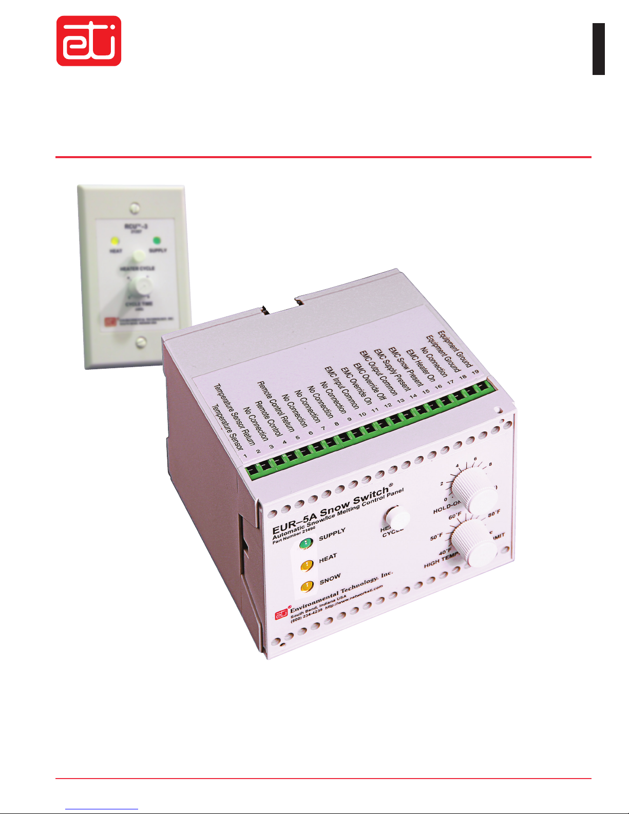
Automatic Snow/Ice Melting System Control
MODEL EUR™–
5A
Installation and Operation Manual
Environmental Technology, Inc.
1850 N Sheridan Street
South Bend, Indiana 46628
(574) 233-1202 or (800) 234-4239
FAX (574) 233-2152 or (888) 234-4238
http://www.networketi.com
21776 Rev. E 09/16 (800) 234-4239 www.networketi.com
Environmental Technology, Inc.
Model EUR–5A Snow & Ice Melting Control
Table of Contents
Product Overview ...................................................... 3
Operation ................................................................... 4
Installation ................................................................. 6
Troubleshooting ...................................................... 10
Ordering Information, Warranty and Service ........... 11
Terminal Connections .............................................. 12
Specifications .......................................................... 13
!
Safety
Make sure that your installation and all electrical connections conform to the NEC (ANSI/NFPA 70) in the
United States of American, to the Canadian Electrical Code in Canada, and to all applicable local electrical codes and laws.
The EUR–5A, RCU–3, and ETI environmental sensor are all rated as NEC Class 2 devices.
Items included
Quantity Description Part Number
1 EUR–5A Snow and Ice Melting Control
1 High Temperature Limit Sensor
1 Power Transformer, 50 VA, 120 V to 24 V
1 RCU–3 Remote Control
1 Fuse Kit
1 EUR–5A Installation and Operation Manual (this document)
21496
25076
14257
21357
21184
21776
2 of 12 Environmental Technology, Inc.
21776 Rev E 09/16(800) 234-4239www.networketi.com
Model EUR–5A Snow & Ice Melting Control
vement-Mounted
120
Product Overview
The EUR–5A snow and ice melting control provides automatic control of a snow and ice melting system.
It includes an interface for environmental sensors, heater contactors, and a building Energy Management
Computer. A remote control is included to supplement the front panel controls.
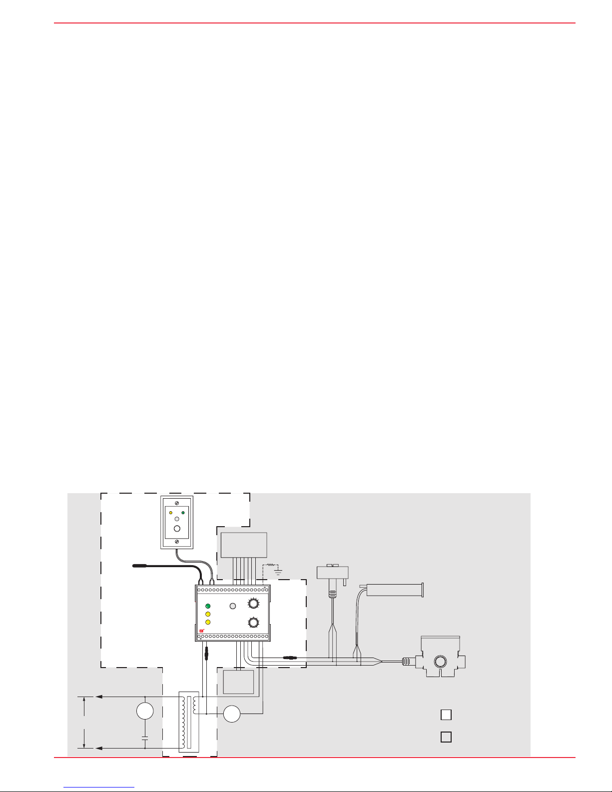
Figure 1 shows a typical snow melting system using the EUR–5A. It is compatible with all ETI snow and ice
sensors including the CIT–1 aerial sensor, GIT–1 gutter sensor, and the SIT–6E pavement sensor. The EUR–5A
also includes a High Temperature Limit Sensor for maximum energy efficiency.
Using at least two environmental sensors improves system performance through superior coverage. A single
environmental sensor can miss tracked or blowing and drifting snow. When multiple sensors are connected,
any one of them detecting snow or ice conditions will signal for the heating process to start.
When snow or ice is no longer detected by the environmental sensors, the heater hold-on time begins. During
hold-on time, heater operation continues for a user-adjustable time interval from 0 to 10 hours. The hold-on time
continues heating for this set amount of time to ensure complete melting and sufficient drying to prevent re-freezing.
The EUR–5A includes an adjustable high temperature limit function. This function has two benefits. The high
temperature limit can save energy by turning the heat off when the temperature is high enough for natural
melting to occur. The high temperature limit is also useful in systems using MI heat cable and other constant
wattage heat cable to prevent unnecessarily high temperatures and excessive energy use. This feature can be
overridden when using self-limiting heaters. The high temperature sensor can be mounted in a place where
it can accurately sense the pavement temperature or ambient air temperature.
Due to the location of the EUR–5A, typically mounted in an electrical enclosure, an additional control location
may be necessary. The EUR–5A comes with an RCU–3 remote control unit that can be mounted in a convenient
place where an operator can monitor conditions and adjust the system operation accordingly.
The EUR–5A provides an interface that can communicate with a building’s Eenergy Management Computer
(EMC) system. The EMC interface provides dry switch contacts for communicating system status and inputs
to allow the EMC to override the EUR–5A.
The EUR–5A operates from a 24 VAC NEC Class 2 power source. A 120 VAC to 24 VAC control transformer is
included for use in installations with 120 VAC power. Since the EUR–5A is an NEC Class 2 device, a customer
supplied auxiliary relay is required for operating the heater control contactors when using electric heat cable.
ETI RCU-3
Remote Control
Figure 1.
Typical EUR–5A
installation
Fuse
Building/Energy
Management
Computrt Interface
Remote
Heater Toggle
Contacts
Aerial Snow Sensor
Equipment
Ground
Fuse
ETI CIT-1
ETI GIT-1
Gutter Ice Sensor
ETI SIT-6E
Pa
Sensor
ETI
Temperature
Limit Sensor
ETI EUR-5A
Snow Switch
Transformer
ETI
Heater Load
Control
CR-2
Contactor
CR-1-1
50 VA
VAC
21776 Rev E 09/16 (800) 234-4239 www.networketi.com 3 of 12Environmental Technology, Inc.
CR-1
Auxiliary
Relay
Included items
Additional items

Model EUR–5A Snow & Ice Melting Control
Operation
The snow and ice melting system normally will operate automatically. When any sensor detects snow or ice,
the heater output will turn on. When snow or ice is no longer present at any of the sensors, then the hold-on
time starts. When the hold-on time is complete the heater output will turn off. If snow or ice is detected during
the hold-on period, then hold-on is canceled while the heat remains on.
The Hold-On Time control sets the amount of time that the heater remains on after snow or ice is no longer
present. This is to ensure that the melting process is complete. An initial setting of 5 hours may be a good
starting point, and observation of the results a few hours after a snow event can allow this to be adjusted
optimally. It’s important that the area becomes dry enough to avoid re-freezing of melt water.
The Heater Cycle pushbutton will turn on the heat even if no snow or ice is detected. The heat will then remain
on for the set hold-on time. If the Heater Cycle pushbutton is pressed again, then the heat will be turned off
(the hold-on time is canceled).
If heat is already on due to snow or ice being sensed, then the Heater Cycle pushbutton will have no effect. If
heat is already on due to hold time, then the Heater Cycle pushbutton will cancel the hold time and turn the
heat off. Pressing the Heater Cycle pushbutton again will reinstate the full hold-on time.
The calibrated 40°F to 90°F (4°C to 32°C) high temperature limit prevents excessive temperatures when
using constant wattage and MI heat cable saving energy and preventing potential damage. It also permits
safe testing at outdoor temperatures too high for continuous heater operation. The temperature limit sensor is
included and must be connected to the system for proper operation. If, for any reason, you need to operate the
system without the high temperature limit sensor you can temporarily replace the sensor with a 470K resistor.
The RCU–3 remote control panel allows user control from a different location. The panel indicators show the
presence of system power and whether the heat is on. The Heater Cycle pushbutton allows control of the heater
Cycle Time. When the Cycle Time time is active, it can be interrupted or reinstated by pressing the button. The
remote Cycle Time control allows adjustment from 2 to 8 hours. This remote Cycle Time applies only when the
remote Heater Cycle pushbutton is used; during automatic operation, the setting at the EUR–5A will be used.
A separate Remote Heater Toggle, a user option, can be connected to function identically to Heater Cycle
pushbutton on the EUR–5A. This allows Heater Cycle operation with the hold time set on the EUR–5A.
The Energy Management Computer connected to the EUR–5A can monitor the system status. Signaling is
provided to the EMC for power supply present, snow present, and heater on/off status. In addition, inputs on
the EUR–5A allow the EMC to override the EUR–5A automatic operation by either holding the heaters on or
holding the heaters off at any time.
4 of 12 Environmental Technology, Inc.
21776 Rev E 09/16(800) 234-4239www.networketi.com
EUR–5A Front Panel
The EUR–5A front panel provides the following controls and indicators:
• SUPPLY indicator – This green LED indicates that the EUR–5A is receiving 24 VAC power.
• HEAT indicator – This yellow LED indicates when the heaters are on. Also it will flash if the high
temperature limit sensor is disconnected.
• SNOW indicator – This yellow LED Indicates when any of the sensors reports the presence
of ice or snow.
• HEATER CYCLE pushbutton – initiates or terminates heater hold-on time.
• HOLD-ON TIME adjustment control – sets the amount of hold-on time from 0 to 10 hours.
• HIGH TEMPERATURE LIMIT – sets maximum temperature from 40°F to 90°F (4°C to 32°C).When that
temperature is reached, the heat will always be turned off.
Model EUR–5A Snow & Ice Melting Control
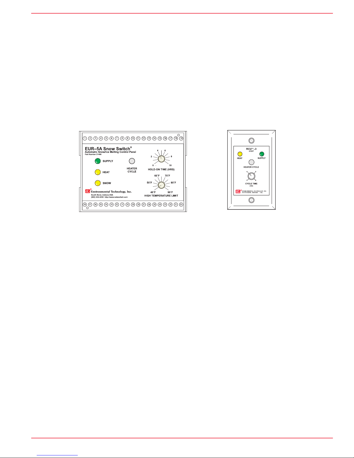
Figure 2.
EUR–5A
front panel layout
Figure 3.
RCU–3
remote control
for EUR–5A
RCU–3 Remote Control Unit
The RCU–3 panel provides the following controls and indicators:
• HEAT indicator – This yellow LED indicates when the heaters are on.
• HEATER CYCLE pushbutton – initiates or terminates Heater Cycle time.
• CYCLE TIME adjustment control – sets the amount of hold-on time from 2 to 8 hours. This hold-on
time is used only when the remote Heater Cycle pushbutton on the RCU–3 is used. Otherwise, the
hold-on time setting at the EUR-5A panel is used.
Remote Heater Toggle
A separate momentary Remote Heater Toggle switch (not included) can be mounted at a convenient accessible
location and connected with the EUR–5A to provide external Heater Cycle control.
This switch will initiate heater operation for the hold-on time set by the EUR–5A. If it is operated during the
hold-on time, then heater operation is terminated.
Energy Management Computer Interface
The EUR–5A provides three contact-closure outputs to the EMC to indicate operational status with indications
of Supply Present, Snow Present, and Heat On.
The EUR–5A automatically controls the snow melting heaters based upon environmental conditions; this is the
default operation of the system. Meanwhile the EMC can also control the EUR–5A by overriding its automatic
operation. The heat can be held on or held off.
21776 Rev E 09/16 (800) 234-4239 www.networketi.com 5 of 12Environmental Technology, Inc.
 Loading...