

Page 1

Ethos Test Instruments, Distributed by MTI,
Victoria Road, Avonmouth, Bristol BS11 9DB
TEL 0117 938 6400 FA X 0117 923 5374
Email: [email protected]
Web: www.ethos-instruments.co.uk
©2015 – Issue 2.V1
8400
17TH EDITION MULTIFUNCTION
INSTALLATION TESTER
USER MANUAL
Page 2

3
EETTHHOOSS 88440000
INSTRUCTION MANUAL
IInnttrroodduuccttiioonn
The Ethos 8400 Multifunction Tester has been designed and built to the
highest standards providing you with a safe and simple solution to your test
requirements.
The Ethos 8400 tester is used to verify the safety of Commercial, Domestic
and Industrial electrical installations. All testing is required to meet the
latest IEE 17th edition of the wiring regulations (BS7671). The Ethos 8400
covers all aspects of these requirements with ease of use and safety in mind.
IInnddeexx
Introduction page 3
Markings & Warnings page 4-5
Unpacking Tester page 6
Operating Tester & Overview page 7-9
Continuity page 9-11
Insulation page 11-13
Socket/Polarity page 14-15
Loop Impedance page 16-21
RCD page 22-26
Phase Rotation page 26
Specification page 27-30
Warranty page 31
2
EETTHHOO SS 8844 0000
INSTRUCTION MANUAL
CCoommpplliiaannccee wwiitthh SSttaannddaarrddss
This tester complies with all the latest UK and European regulations.
This tester has been tested according to the following regulations:
BS EN 61010-2-030:2010 - Safety requirements for electrical equipment for
measurement, control and laboratory use. Particular requirements for testing and measuring
circuits.
BS EN 61326-2-2:2013 - Electrical equipment for measurement, control and laboratory
use. Particular requirements for portable test, measuring and monitoring equipment used in
low-voltage distribution systems.
BS EN 61557:2007 - Electrical safety in low voltage distribution systems up to 1000V AC.
and 1500V DC. Equipment for testing, measuring or monitoring of protective measures.
Part 1: General Requirements
Part 2: Insulation Requirements
Part 3: Loop Requirements
Part 4: Continuity Requirements
Part 6: RCD Requirements
Part 7: Phase Rotation Requirements
Part 10: Multifunction Requirements
Page 3

When working on live circuits, use of a proving unit such as the Ethos
4299 is recommended to establish correct function of the tester.
If the equipment is used in a manner not specified by the
manufacturer, the protection by the equipment may be impaired.
Disconnect from external circuits before removing battery cover.
Inspect the tester and accessories for damage before use and do not
use if damage is found.
To prevent possible electrical shock, fire, or personal injury:
Use the product only as specified, or the protection supplied by the
product can be compromised.
Do not use the product around explosive gas, vapour or in damp or
wet environments.
Do not use test leads if they are damaged. Examine the test leads for
damaged insulation, exposed metal, or if the wear indicator shows.
Check test lead continuity.
Use only approved Ethos accessories such as test leads etc supplied
with the instrument. Part numbers of replacement leads on page 6.
Do not use the product if it is damaged.
To be repaired by Ethos authorised agents only.
Do not apply more than the rated voltage between the terminals or
between each terminal and earth ground.
Remove test leads from the tester before battery cover is removed.
Do not operate the product with covers removed or the case open.
Hazardous voltage exposure is possible.
Use only specified replacement fuse. Fuse type F0.5A, 500V, HRC,
6.3 x 32mm.
Keep fingers behind the finger guards on the probes at all times.
Connect the common test lead before the live test lead and remove
the live test lead before the common test lead.
Use Personal Protective Equipment (approved rubber gloves, face
protection, and flame-resistant clothes) to prevent shock and arc
blast injury where hazardous live conductors are exposed.
5
EETTHHOO SS 8844 0000
INSTRUCTION MANUAL
MMaarrkkiinngg EExxppllaannaattiioonnss
Warning! Refer to manual.
Caution! Voltage present. Risk of Electric Shock.
Earth
Double Insulation
This instrument should be recycled as electronic waste.
User accessible fuse in battery compartment - F0.5A, 500V, HRC 6.3 x 32mm
Prohibited to use for the Electrical System which uses the voltage above 550V.
Conformity to European Standards
CAT III Testers are designed to protect against transients and fault currents in fixed
equipment installations at the distribution level. Examples are measurements on
distribution boards and socket wiring.
CAT IV Testers are designed to protect against transients and fault currents from the
primary supply level (overhead or underground utility service). Examples are
measurements made before the main fuse or circuit breaker.
SSaaffeettyy
Before using the Ethos 8400 or accessories read this instruction
manual carefully to ensure a safe understanding of the symbols and
use of this tester
See above for a list of symbols used on the product and in this
manual.
A Warning identifies hazardous conditions and actions that could
cause bodily harm or death.
A Caution identifies conditions and actions that could damage the
instrument or cause permanent loss of data.
WWaarrnniinnggss::
RReeaadd BBeeffoorree UUssiinngg
To maintain operator safety use only specified Ethos accessories.
4
EETTHHOO SS 8844 0000
INSTRUCTION MANUAL
CAT III
CAT IV
Page 4

7
EETTHHOO SS 8844 0000
INSTRUCTION MANUAL
UUnnppaacckkiinngg tthhee TTeesstteerr
Your Ethos 8400 Multifunction Tester comes complete with:
D
ESCRIPTION PART NO QTY
Multifunction Tester Ethos 8400 1
Instruction Manual 1
3 Wire Split Lead Ethos 2125 1
Assembly with Probes +
Crocodile Clips Brown/Blue/Green
13 Amp Mains Lead to 4mm Ethos 2126 1
Connections Brown/Blue/Green
Remote Switch Probe Ethos 2127 1
AA LR6 Alkaline Battery Duracell 6
Heavy Duty Carry Case Ethos 8001 1
Neck Strap Ethos 2128 1
Certificate of Calibration 1
Warranty Registration Card (terms of 3 year warranty) 1
All the parts listed above are included in the carry case.
6
EETTHHOO SS 8844 0000
INSTRUCTION MANUAL
OOppeerraattiinngg tthhee EEtthhooss 88440000
To insert batteries ensure the instrument is switched
off and no test leads are connected.
Remove battery cover from base of unit, insert
batteries into holder ensuring correct polarity.
Replace cover.
Always use good quality LR6 AA Alkaline Batteries.
Re-chargeable batteries are not suitable.
Battery power level indicated on the colour display by the symbol shown.
Please dispose of your batteries carefully.
Batteries are made from important resources and chemicals,including
lead, cadmium,zinc, lithium and mercury. If batteries are disposed of as
normal waste, they’ll be taken to a landfill site and those resources will be
lost and will contribute to the pollution of the environment. Recycling is
one way you can help the environment and you should dispose of used
batteries separately from other waste, using local collection and recycling
schemes available.
To clean the tester use a damp cloth do not use any solvents. Do not allow
any water ingress and ensure tester is fully dry before use
When replacing/removing fuse from inside battery compartment do not use any sharp
implements for this task.
OOvveerrvviieeww
Front panel and controls
Page 5

9
EETTHHOO SS 8844 0000
INSTRUCTION MANUAL
8
EETTHHOO SS 8844 0000
INSTRUCTION MANUAL
Top View
OOppeerraattiinngg tthhee EEtthhooss 88440000
All test Functions are selected by using the main rotary switch.
1 Power off.
2 Socket/Polarity Test
3 No Trip Earth Loop Impedance Test
4 High Current Earth Loop Impedance Test
5 30mA Auto Sequence Type G RCD Test
6 30mA RCD Test (Manual) Type G
7 100mA RCD Test (Manual) Type G
8 300mA RCD Test (Manual) Type G
9 500mA RCD Test (Manual) Type G
10 100mA RCD Test (Manual) Type S
11 300mA RCD Test (Manual) Type S
12 Phase Rotation Test
13 1000V Insulation/Resistance Test
14 500V Insulation/Resistance Test
15 250V Insulation/Resistance Test
16 Continuity Test
OOppeerraattiinngg tthhee EEtthhooss 88440000
Push Buttons
1 Test Button - Initiates all selected tests.
2 Test Lock - Hands Free function for
Continuity,Insulation & Loop
3 PFC/Loop - Prospective fault current
value after Loop Test Result
4 RCD Recall - List the last set of RCD
Test Data from an Auto sequence Test
5 Continuity Null - Nulls the Resistance
Value from the Test Leads in use
6 Polarity Test Pad - Unique safety
function ensuring correct mains polarity
AAuuttoo ppoowweerr ooffff ffuunnccttiioonn
To ensure long battery life the Ethos 8400 will
automatically power off when standing idle for 3
minutes.To power the Ethos 8400 either return the selector switch to “OFF” and then back to
the test selection or simply press any of the four buttons under the display screen.
TTeesstt && MMeeaassuurreemmeenntt FFuunnccttiioonnss
IInnssuullaattiioonn aanndd CCoonnttiinnuuiittyy
CAUTION
Measurements shall only be carried out on de-energised circuits.
If the tester is connected to a live circuit (25V or greater), the LED will flash red and the
hazard buzzer will sound.Your Ethos 8400 is fully protected but measured RMS voltage
will be displayed on the secondary/lower display. Further testing after this point will be
inhibited.To resume testing, disconnect the test leads and isolate the circuit.
All equipment and appliances should be disconnected from the circuit under test.
Attached equipment may be damaged by the higher voltages applied during testing and
may return an artificially low test result.
There may be capacitance on the circuit being tested.Your tester will automatically
discharge this but do not disconnect the test leads or change tester function until autodischarge has completed.
1
23456
1
2
3
4
5
6
7
8
9
4
10
11
12
13
4
14
15
16
Page 6
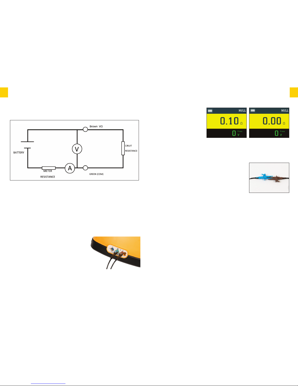
LLeeaadd NNuulllliinngg
Test Leads are nulled to ensure
accurate resistance values of
circuit under test. To achieve
this you must null the
resistance of the leads in use.
Using the croc clips connect
the open ends of the test leads
together firmly ensuring a good connection, then press
continuity null button, the instrument will display the resistance
value of the test leads, then press the test button, the display
will then show 0.00Ω and your test leads are successfully
nulled. The word Null will appear on the display.
IMPORTANT – When connecting the croc clips they must
be connected as diagram shown this ensures that the best
point of contact is made to give the most accurate
resistance value of the leads that will be used for testing.
If inserting new or different length leads you must repeat
process above.
N.B. Nulled results will be stored until user reset. To reset
simply leave the Ethos 8400 in continuity mode and open circuit i.e. do not have leads
connected. Then press NULL this will then remove the null function.
The Ethos 8400 is now correctly set up to perform continuity testing on a circuit.
You can also set up your Ethos 8400 to be used in hands free mode on continuity by simply
pressing the test lock button and then pressing test.T-Lock will flash at the top of the screen to
indicate you are on hands free mode.To deactivate simply press test lock button again.
IInnssuullaattiioonn
WARNING
Do not touch the ends of the test leads while on the Insulation test functions as they are
energised.
Results of measurements can be adversely affected by impedances of additional
operating circuits connected in parallel or by transient currents.
11
EETTHHOO SS 8844 0000
INSTRUCTION MANUAL
During continuity measurement current flows from battery positive through the Brown (VΩ)
lead, external circuit resistance, Green (COM) lead, meter resistance and finally back to the
battery negative.
The current and voltage are measured as shown on page 9 and the external resistance
calculated. When the leads have previously been nulled, their resistance is subtracted before
displaying the reading.
The purpose of Continuity Testing is to establish the resistance of the circuit under test.
TTeesstt PPrroocceedduurree
Insert the brown test lead into the brown input terminal & the blue test lead into the green
terminal.
The brown test lead can be substituted by using the red
remote test probe supplied.This allows remote
activation of the Ethos 8400 from the safety of the test
probe ensuring that you are always looking at the point
of contact and not the Ethos 8400.
Select continuity on the rotary switch.
10
EETTHHOO SS 8844 0000
INSTRUCTION MANUAL
CCoonnttiinnuuiittyy
PPrriinncciippaall ooff MMeeaassuurreemmeenntt
Page 7
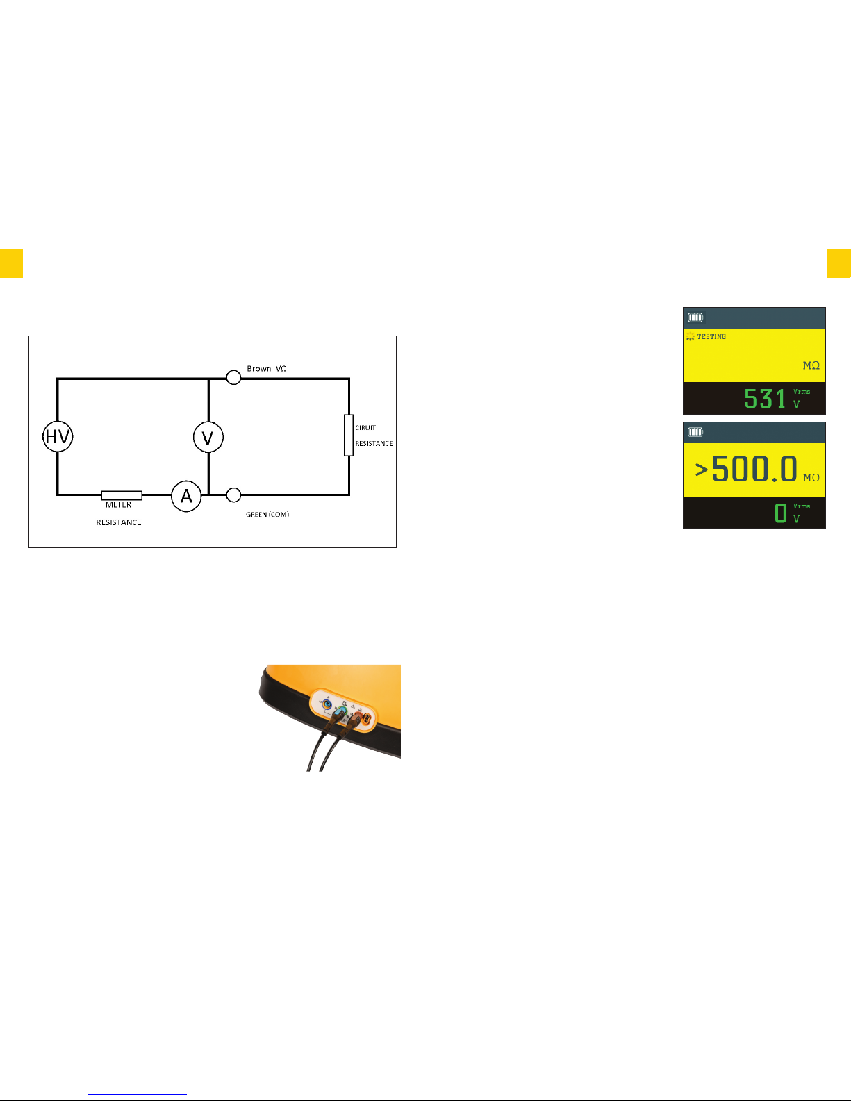
PPrriinncciippllee ooff MMeeaassuurreemmeenntt
During insulation measurement the tester generates a high voltage internally.The positive side of
this is connected to Brown (VΩ) lead causing a very small current to flow through the external
insulation resistance, Green (COM) lead, meter resistance and finally back to the negative side
of the HV generator.
The current and voltage are measured as shown and the external resistance calculated and
displayed.
TTeesstt PPrroocceedduurree
Insert the brown test lead into the brown input terminal
& the blue test lead into the green terminal.
The brown test lead can be substituted by using the red
remote test probe supplied.This allows remote
activation of the 8400 from the safety of the test probe
ensuring that you are always looking at the point of
contact and not the Ethos 8400.
Select insulation on the rotary switch either 250V,
500V,1000V setting as required.
Connect the brown test lead to the phase conductor and
the blue test lead to the other conductor under test and
press the test button.
The tester will beep indicating voltage output through
the test leads and the circuit under test. The display will
indicate output voltage then display the result of test in
MΩ. 0V output will indicate if finished and no voltage
present.
When test is activated the red Voltage/Polarity will flash
warning there is voltage on the leads and circuit under
Tes t .
HHaannddss FFrreeee
HHaannddss FFrreeee IInnssuullaattiioonn TTeessttiinngg
To enable the hands free feature simply press Test Lock
button once,The ‘T-LOCK’annunciator will appear
flashing on the display and will continue to do so until
cancelled by a further press of the Test Lock button or by changing the function selector switch.
When the ‘T-LOCK’ annunciator is flashing a single press of the test button will toggle
continuous testing on and off.
Once started a steady beeping tone will be emitted to indicate that measurement is being taken.
After a second or two the test result will be displayed in the primary display area and an audible
tone will indicate either by a single beep that the result is a value above 2MΩ or by a short 2
tone alarm that the result is a value under 2MΩ. The secondary display area will show the
terminal voltage being applied.
The tester will continue to take the measurement and any further change to the resistance of the
circuit will be indicated by an audible tone as described above and a change of result on the
display.
Whilst testing in hand free mode the red warning LED will flash to warn of the voltage between
the prod tips/crocodile clips.
A further single press of the test button will suspend measurement.
13
EETTHHOO SS 8844 0000
INSTRUCTION MANUAL
12
EETTHHOO SS 8844 0000
INSTRUCTION MANUAL
Page 8
PPoollaarriittyy TTeesstt PPaadd
Your Ethos 8400 tester has a special polarity test
function.
It is a little known fact that a system can be
reverse wired with Live (Phase) to earth/neutral
and earth/neutral to Live (Phase) The sockets will
all work and conventional loop testers will show
and test that everything is correct despite this very
dangerous wiring condition.
Although extremely rare, this dangerous condition
can exist so if your test shows this fault do not
proceed - if in any doubt advise your customer to
contact their supply company immediately.
Touch the touchpad area next to the test button.
There should be no change in the indication given.
If the Voltage/Polarity LED flashes Red and a
warning tone is emitted when the touchpad is
touched a potentially dangerous polarity reversal
exists. Do not proceed. If in any doubt advise the
customer to contact the electricity supply company
immediately.
15
EETTHHOO SS 8844 0000
INSTRUCTION MANUAL
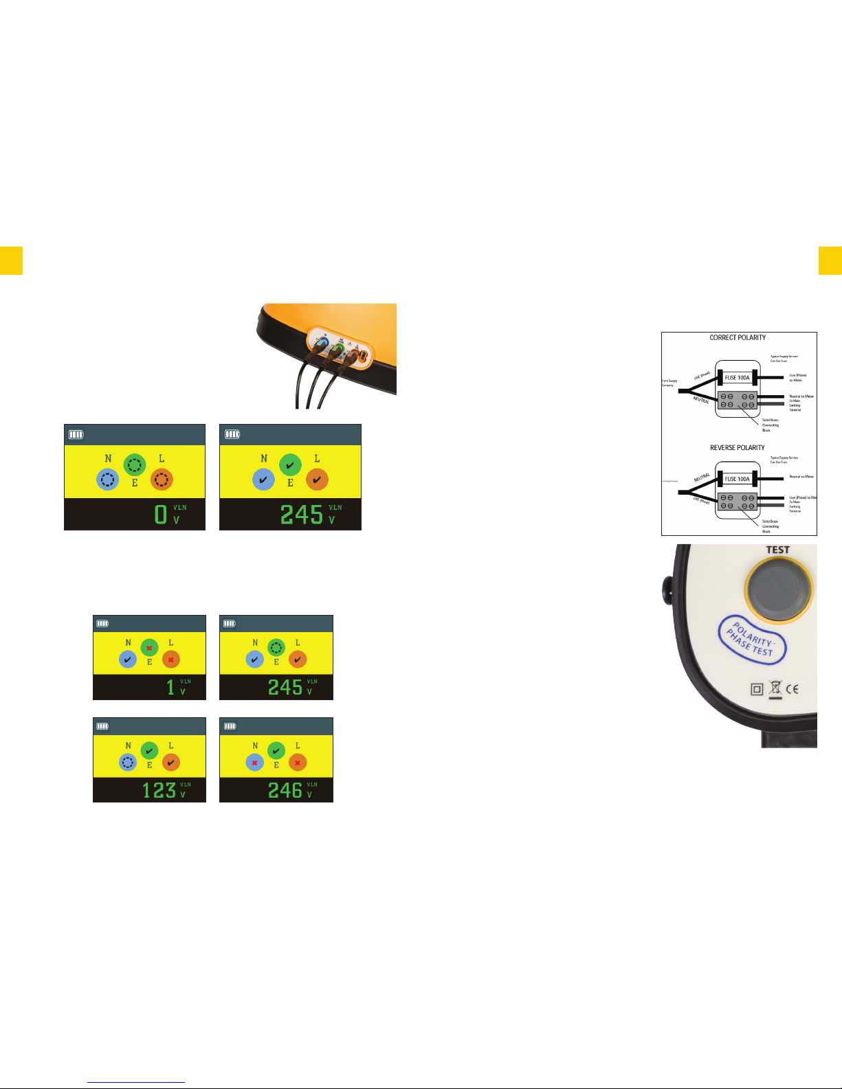
Socket Testing
The Ethos 8400 has a unique feature for testing
sockets.
Switch the rotary dial to socket, insert 13 amp mains
test lead and the brown, blue & green into the
corresponding input terminals on the tester.
Plug the 13 amp mains plug into the socket under test.
If there is no voltage present the If there is voltage present and the
above will be displayed. wiring is correct the above will be
displayed. Correct wiring is indicated by a
tick in each of the phase colours.
If there is incorrect wiring dependent on the issue the following screens will appear.
14
EETTHHOO SS 8844 0000
INSTRUCTION MANUAL
Reversed Live/Earth Missing Earth
Missing Neutral Reversed Polarity
Page 9
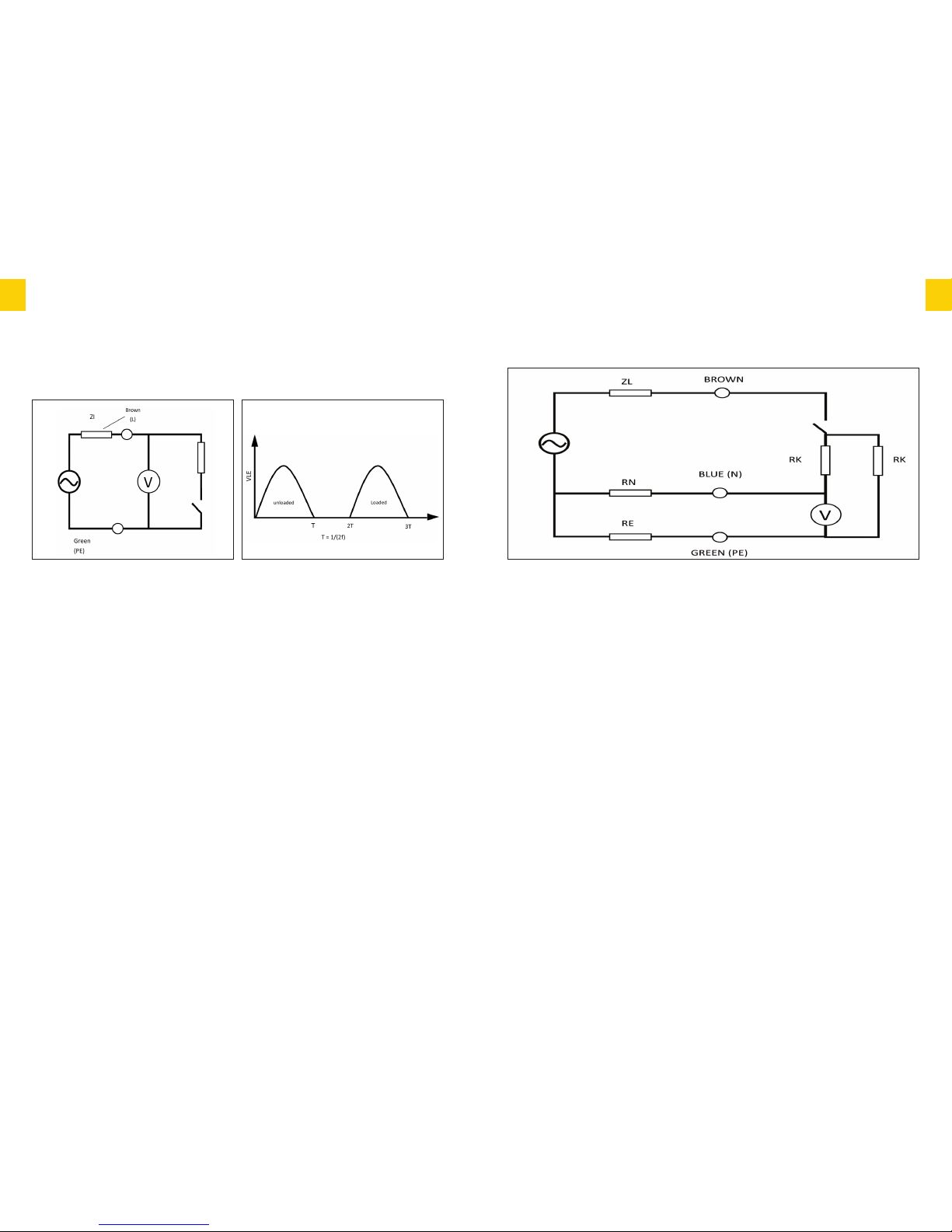
Hi-I Line-Earth loop measurement takes place in several steps:
a) The tester measures an unloaded half-cycle of the mains.
b) The tester switches in load RL.This causes the mains circuit to be slightly
attenuated due to the effective source impedance.
c) The tester measures a second half-cycle with the mains still loaded.
d) The load is removed.
The resistive part of ZI is calculated from the unloaded and loaded half-cycle measurements.
Each pair of measurements is taken adjacently to minimize noise and several such pairs may be
used for best accuracy.
The inductive part of ZI is calculated from the unloaded and loaded half-cycle durations. Any
inductance causes a measurable lag in the loaded half-cycle.
Note: when testing on a supply with inductance exceeding 1mH or phase angle exceeding 30°
accuracy may be reduced.
17
EETTHHOO SS 8844 0000
INSTRUCTION MANUAL
16
EETTHHOO SS 8844 0000
INSTRUCTION MANUAL
Principle of Measurement – No-Trip
The No-Trip Line-Earth loop range measures the same circuit value ZI using a two-stage
technique.
In the first stage the Live-Neutral loop impedance ZLN is measured using the same principle as
for Live-Earth loop.
The second stage is similar to Hi-I but operates at a low current to avoid tripping RCDs
CAUTION
Although fully protected against over voltage to 550VAC this tester should only be used
on a 230V supply.
Important note for calibration check box users: The smart loop test system used by the
Ethos 8400 is immune to sudden high value changes such as voltage spikes. As a result
when changing calibration or check box loop values the tester or the supply must be
switched off between changes of calibration values.
The Ethos 8400 Loop test function has 2 modes for Loop testing that allow the user to
conduct the most accurate test possible whether or not the circuit under test is
protected by an RCD.
IInntteerrmmiitttteenntt OOppeerraattiioonn
The Ethos 8400 is designed for a large number of loop tests in rapid succession. In the unlikely
condition this limit is exceeded a thermometer will be shown on the display until the unit cools
down.Testing will be inhibited while the thermometer is shown.
LLoooopp IImmppeeddaannccee TTeessttiinngg
Principle of Measurement – Hi-I
Page 10

NNoo TTrriipp MMooddee
For Zs testing where the circuit being tested is protected by an RCD there is the No Trip Loop
Test mode. In this mode testing can be made at sockets on the final circuit without fear of
tripping the RCD under normal circumstances.
This is achieved by testing at a current that is too low to trip an RCD on an otherwise healthy
circuit. The No Trip test is a 3-wire test that also checks the Live, Neutral/Earth conductors are
correctly connected before running the loop test.
Note- if there is abnormal standing leakage current on the circuit such as a faulty Microwave
Cooker for example then this abnormal leakage is added to low current used for the above test
and the RCD may trip.
However this can be seen as an advantage since it is pointing to a faulty appliance that should
be rectified or replaced.
Whilst No-Trip testing at points on the final circuit will normally function with a high level of
accuracy,it should be noted that the low current measurement technique used is more likely to
be adversely affected by external factors such as noise on the mains supply.
Circumstances such as testing at seldom used socket outlets with tarnished contacts or testing a
circuit with a lot of background noise from electronic apparatus can result in the occasional
erroneous reading.
For this reason it is recommended that multiple measurements are made when using the No-trip
mode and any isolated odd results are ignored. When taking multiple readings the tester should
be disconnected from the supply between consecutive tests.
For safety reasons the No-Trip mode is recommended for all measurements made on TT
systems.
Where practical all other equipment powered by the same circuit should be switched off before
testing. This will reduce the chances of the RCD tripping as a result of combined leakages.
PPFFCC//PPSSCC
In both Loop test mode the Ethos 8400 will also display the supply voltage and at the touch of
the PFC button the PFC/PSC depending on being connected L-E or L-N will be displayed.
TTeesstt lleeaadd ccoonnffiigguurraattiioonn
The Ethos 8400 Loop test function can be used with 2 types of connecting lead. It is important
to understand and use the correct lead configuration for each test mode or you may not obtain
the correct results.
Lead options
Ethos 2126 mains lead with 3 x 4mm plug to 13A plug
Ethos 2125 3-pole distribution board test lead set that can be fitted with either prod tips or
crocodile clips as required.
19
EETTHHOO SS 8844 0000
INSTRUCTION MANUAL
Mains supply wiring and voltage test
When first connected to a mains supply the Ethos 8400 will automatically conduct a safety test
to ensure that the Live, Neutral and Earth conductors are all connected correctly and that the
supply voltage is in the acceptable range (207-230V)
If all is well the VOLTAGE/POLARITY warning LED will light Green and the supply voltage will
be displayed in the primary display area.
In the event of a problem with either the mains voltage supply or reversed connections the
VOLTAGE/POLARITY warning LED will light Red, a warning tone will be sounded and testing
will be inhibited.
This condition will be indicated for you safety.
LLoooopp TTeesstt PPrroocceedduurreess
HHaannddss FFrreeee LLoooopp TTeessttiinngg
The hands free feature can be used in either No Trip or high current test modes.
To enable the hands free feature simply press Test Lock button once,The ‘T-LOCK’annunciator
will appear flashing on the display and will continue to do so until cancelled by a further press
of the Test Lock button or by changing the function selector switch.
When the ‘T-LOCK’ annunciator is flashing all you need to do is connect the test lead to a mains
supply and the test will be carried out.
HHiigghh CCuurrrreenntt mmooddee
For Ze testing at the distribution board or at any point upstream of RCD protection there is a
traditional fast high current test mode. The high current mode is a 2-wire test that enables the
user to test the true impedance of both the Line-Neutral Loop and the Line-Earth loop and
therefore to establish both the PSC (prospective short circuit current) and the PFC (prospective
fault current) for the installation.
Unlike most testers that only measure the resistance of the Loop, the high current mode of the
Ethos 8400 will measure the impedance of the Loop which includes an element of reactance.
This can be significant where the distribution board is close to the mains supply transformer and
is therefore much more accurate than older Loop testing techniques.
You should be aware that because of this there may well be variations in reading compared to
ordinary loop testers or to the non-trip function of this tester, particularly when the
measurement is made near to the mains supply transformer.
18
EETTHHOO SS 8844 0000
INSTRUCTION MANUAL
Page 11
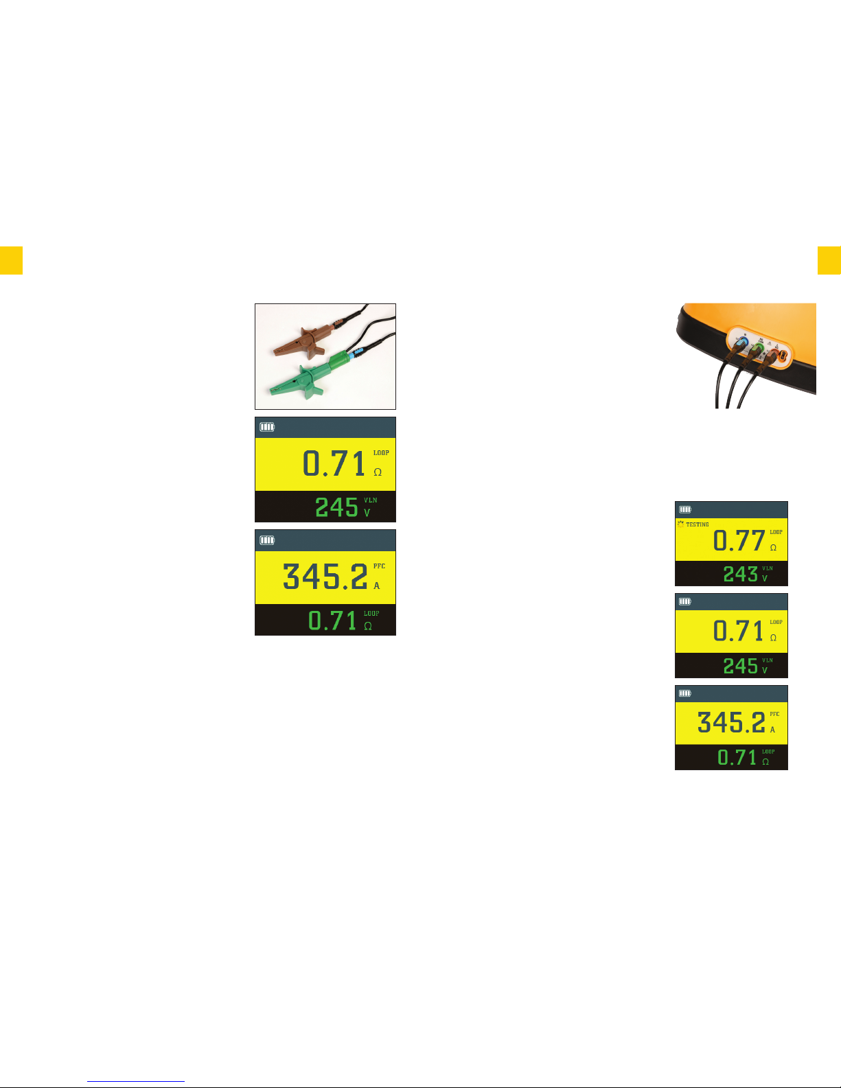
NNoo TTrriipp LLoooopp tteesstt ((ZZss))
Connect the brown, blue and green test leads to the
corresponding output terminals on the tester.
The brown test lead can be substituted by using the red
remote test probe supplied.This allows remote
activation of the Ethos 8400 from the safety of the test
probe ensuring that you are always looking at the point
of contact and not the Ethos 8400.
If testing the loop impedance at a socket plug in the
13amp plug and switch on the power.
N.B. The circuit under test must be live to loop testing.
The test will be inhibited if the wiring is incorrect
polarity on the circuit under test.
Rotate the function selector switch to ‘NO TRIP’
Connect the test lead to the socket/circuit under test.
Providing that the connections are correct and the
supply voltage is within the correct range the
VOLTAGE/POLARITY LED will light Green, the Ethos
8400 will start taking some background measurements
and will display the Line Neutral supply voltage
Voltage will be displayed. Then press the test button.
The screen will show a symbol and the word testing.
The result of the test will be shown in the primary
display.
A single press of the PFC Loop button will toggle the
display so that the PFC is shown in the primary display
and the impedance in the secondary display. A further
press will toggle the results between the primary and
secondary displays.
The leads are an integral part of the tester set-up and
should accompany the tester when being returned for recalibration or service. Do not use any other type of
mains lead or test lead set.
21
EETTHHOO SS 8844 0000
INSTRUCTION MANUAL
2 Wire lead configuration Brown (live) Blue(neutral)
Green (earth) The neutral is inserted into the back of
the earth lead to give a combined contact for 2 wire test
method.
The brown test lead can be substituted by using the red
remote test probe supplied.This allows remote
activation of the Ethos 8400 from the safety of the test
probe ensuring that you are always looking at the point
of contact and not the Ethos 8400.
HHiigghh ccuurrrreenntt tteesstt ((ZZee))
The high current should only be conducted with the
distribution board test lead set Ethos 2125 configured
in 2 wire mode. Do not use this function with the Ethos
mains lead 2126 or the distribution lead set in 3-wire
configuration.
Rotate the function selector to the HIGH I position.
Connect the test lead probes to the circuit under test
and press the test button.
The result will be shown in the primary display and the
mains voltage will be shown in the secondary display.
Press the PFC/LOOP button to show the PFC/PSC in
the primary display depending on being connected L-E
or L-N and the impedance in the secondary display
area.
Note: The reading described here as PFC/PSC will be
the prospective fault current for the circuit being
immediately tested. This is known as PSC in the case of
a test between Live and Neutral or PEFC for a test between Live and Earth conductors.
The 17th edition wiring regulations 2008: amendment 1 2011,call for an IPF value to be
recorded, this is the higher of the PSC and PEFC as described above.
20
EETTHHOO SS 8844 0000
INSTRUCTION MANUAL
Page 12
PPrriinncciippllee ooff MMeeaassuurreemmeenntt –– RRaammpp
During RCD Ramp testing, the earth leakage current starts at 20% of RCD rated current and
increases by 10% of RCD rated current every 300ms up to a maximum of 110%. For example
a 30mA Ramp test runs from 6mA to 33mA.
The trip time is measured as in the normal case and the trip level calculated from it.
RRCCDD TTeesstt FFuunnccttiioonn
CAUTION
Although fully protected against over voltage to 550VAC this tester should only be used
on a 230V supply.
The Ethos 8400 will test all the most commonly encountered RCD’s of both standard (AC) type
and selective (ACS) type across the full range of tests required by the 17th Edition of the wiring
regulations.
Test requirements
Each RCD is tested to ensure that:
It is not prone to ‘nuisance’ tripping as does not trip when a fault of half its rated current
is introduced. This is referred to as the x1/2 test.
It operates with a maximum disconnection time of 300ms (AC type) when a fault at its
rated current is introduced.This is referred to as the x1 test.
In the case of an RCD rated at 30mA there is an additional requirement that it operates
with a maximum disconnection time of 40ms when a fault of five times its rated current is
introduced.This is referred to as the x5 test.
For the reasons explained below all of the above tests have to be conducted at both 0° and 180°
this means that four tests (or for 30mA RCD’s six tests) have to be made for each RCD.
The user friendly design of the Ethos 8400 simplifies the test process by enabling you to do any
of these tests by making just two function selections.
SSiinnuussooiiddaall ppoollaarriittyy ((tthhee 00°° oorr 118800°° tteesstt))
RCD’s often operate with different reaction times depending upon whether the fault is
introduced during the positive or negative half cycle of the AC waveform. Therefore to
accurately determine the maximum response time of an RCD it is necessary to test it twice at
each given fault current,firstly with the fault introduced during the positive half cycle and
secondly during the negative half cycle.
The Ethos 8400 takes care of this for you by alternating the start point of consecutive tests at
any given setting. If for example you have selected a test at the rated trip current (x1) of a
100mA RCD, the first press of the tes t button will apply a 100mA fault current starting on the
positive half cycle (0°) and display the result. A further press of the test button will carry out
another test at the same current but starting on the negative half cycle (180° ).
23
EETTHHOO SS 8844 0000
INSTRUCTION MANUAL
RRCCDD
WARNING
Leakage currents in the circuit following the residual current protection device may
influence the measurements.
Potential fields of other earthing installations may influence the measurement.
Special conditions in S-type residual current protective devices shall be taken into
consideration.
Equipment connected downstream of a residual current protective device (RCD) may
cause considerable extension of the operating time.Examples of such equipment might
be connected capacitors or running motors.
22
EETTHHOO SS 8844 0000
INSTRUCTION MANUAL
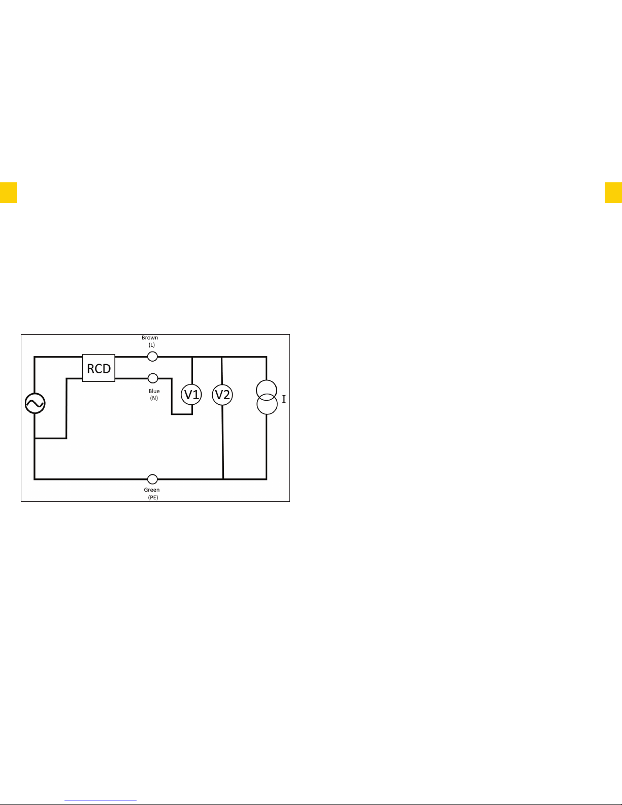
PPrriinncciippllee ooff MMeeaassuurreemmeenntt –– xx11//22,, xx11,, xx55
During normal RCD test an earth leakage current (I) is applied to unbalance the RCD.
During application of the current, VLN is monitored using voltmeter V1 for an RCD trip
signature.When trip occurs, the time from application of the earth leakage current to the trip is
calculated and displayed.
Additionally, VLE is measured using voltmeter V2 to monitor Fault Voltage. If excessive Fault
Voltage is detected, testing is aborted and a warning is displayed.This detection uses the actual
Fault Voltage occurring during the test and not the predicted fault voltage at the rated residual
current.
Application of the current is limited in duration. If no trip is detected during the application,an
over range reading is displayed. Note: when testing at x1/2, no trip is a PASS.
Page 13
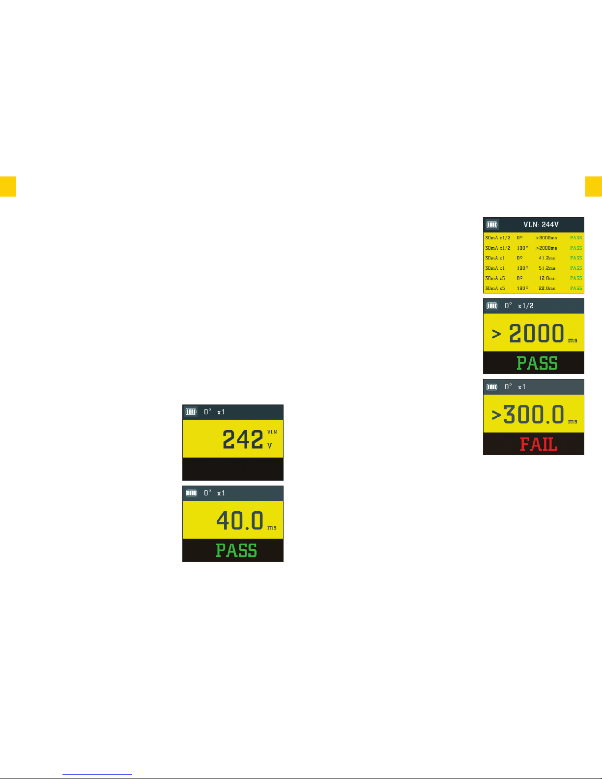
AAuuttoommaattiicc tteesstt
For the most commonly encountered 30mA RCD the
test process is even simpler. Just turn the rotary
selector to the ‘30mA AUTO’ setting and the Ethos
8400 will conduct all six required tests at a single touch
of a button. Then when the RCD under test “trips” reset
the RCD and continue to do so until the test procedure
is complete then return to your 8400 where all results
will be displayed on one screen.
PPaassss oorr FFaaiill rreessuulltt
In addition to displaying the time taken for the RCD to
trip the Ethos 8400 will also indicate whether it has
passed or failed the test requirement of the 17th
edition.
The main display shows that the fault current was
supplied for over 2000 milliseconds (2 seconds) without
tripping the RCD. The secondary display confirms that
this passes the requirements of the 17th edition.
In the event of the RCD failing the test and tripping
within 2 seconds at half the rated current the main
display will show the trip time and the secondary display
will show ‘FAIL’. A shor t 2 tone alert will also sound.
After displaying the result for a few seconds the tester
will switch to the 180° phase polarity setting in
readiness for the next test.
When both tests have been conducted at the x1/2
setting press the multiplier button to change the test
current to the x1 setting.
Press the test button to conduct a test at the x1 setting a 0°. The result will be shown as a pass
if RCD trips within 300ms. After displaying the result for a few seconds the tester will switch to
the 180° phase polarity setting in readiness for the second test at the x1 current setting.
If the 30mA setting has been selected at the x5 current option will be available by using the
multiplier button. This option is not available or required for other ratings.
RRaammpp tteesstt
The Ethos 8400 also includes a diagnostic Ramp test feature. In this mode rather than
applying a steady fault current and measuring the time taken for the RCD to trip, the
Ethos 8400 gradually increases the fault current and identifies the level of additional leakage at
which the RCD trips.
25
EETTHHOO SS 8844 0000
INSTRUCTION MANUAL
TTeesstt LLeeaaddss
Where testing is to be conducted at a point on the circuit other than a socket outlet the
distribution board test lead set Ethos 2125 is used in 3-wire mode as described in the previous
chapter. The probes can be fitted with either prod tips or crocodile clips as required.
Mains supply wiring and voltage test
When first connected to a mains supply the Ethos 8400 will automatically conduct a safety test
to ensure that the Live, Neutral/Earth conductors are correctly connected and that the supply
voltage is in the acceptable range of 207-253V.
If all is well the VOLTAGE/POLARITY warning LED will light Green and the supply voltage will
be displayed in the primary display area.
In the event of a problem with either the mains voltage supply or reversed connections the
VOLTAGE/POLARITY warning LED will light Red, a warning tone will be sounded and testing
will be inhibited.
RRCCDD tteesstt pprroocceedduurree
Select the type and rating of the RCD to be tested with the rotary function selector switch.
Connect the 4mm plugs of the chosen test lead to the corresponding L, N & E terminals of the
Ethos 8400 and connect the other end to the socket or circuit terminals under test.
If using the distribution board test lead set Ethos 2125
observe the correct polarity by connecting the Brown
probe to the Live conductor, Blue to Neutral and Green
to Earth.
UUsseerr sseelleecctteedd tteesstt
The recommended order of tests is firstly at 1/2x the
rated current followed by a test at the rated current and
finally, for 30mA RCD’s only, 5x the rated current.
The default test parameters of x1/2 x1 x5 for the
current multiplier and 0° for the phase polarity will be
automatically selected for the first test. These will be
displayed on the LCD along with the Live-Neutral
voltage.
Press the test button and a test will be conducted at
these settings. If successful and the RCD has failed to
trip a single beep will sound and the main display will be
similar to this example
24
EETTHHOO SS 8844 0000
INSTRUCTION MANUAL
Page 14
27
EETTHHOO SS 8844 0000
INSTRUCTION MANUAL
EETTHHOO SS 8844 0000
INSTRUCTION MANUAL
Measurement Specifications and Accuracies
LLoooopp // PPFFCC--PPSSCC
HHiigghh CCuurrrreenntt::
2 wire test Live – Earth or Phase - Phase, 7A nominal at 230V.
MEASUREMENT ACCURACY SYSTEM VOLTAGE SYSTEM VOLTAGE OVER VOLTAGE PROTECTION
RANGE RANGE FREQUENCY
(BS EN 61557-10)
0.00Ω to 500.0Ω ± (3% 100-440VAC 50-60Hz 550V
+ 3 digits)
NNoo--ttrriipp::
3 wire test Live-Earth, 13 mA nominal at 230V, max 5Ω Neutral impedance.
MEASUREMENT ACCURACY SYSTEM VOLTAGE SYSTEM VOLTAGE OVER VOLTAGE PROTECTION
RANGE RANGE FREQUENCY
(BS EN 61557-10)
0.00Ω to 500.0Ω ± (5% 195-253VAC 50-60Hz 550V
+ 5 digits)
General Specifications
DIMENSIONS H 115mm W 245mm D 140mm
WEIGHT (WITH BATTERIES) 965g
BATTERY TYPE 6 x AA / LR6 Alkaline
BATTERY LIFE (TYPICAL) Idling: 13.5 hours
1
Insulation according to BS EN61557-2: 1008 tests
Continuity according to BS EN61557-4: 960 tests
PROTECTIVE DEVICE F0.5A, 500V, HRC 6.3 x 32mm
LCD
DISPLAY TFT (Thin-Film-Transistor) Colour LCD 3.5” Diagonal
320xRGBx240 pixels
CATEGORY RATING 300V CAT IV
600V CAT III
INGRESS PROTECTION RATING IP54
OPERATING TEMPERATURE 0°C to 40°C
STORAGE TEMPERATURE -10°C to 60°C
OPERATING HUMIDITY 80% @ 31°C to 50% @ 40 °C
0PERATING ALTITUDE 0 to 2000m
Specification
This is particularly useful in diagnostic testing of
circuits where nuisance tripping is a problem and helps
to identify the difference between an over sensitive RCD
and excessive leakage from poor insulation or
equipment with high leakage.
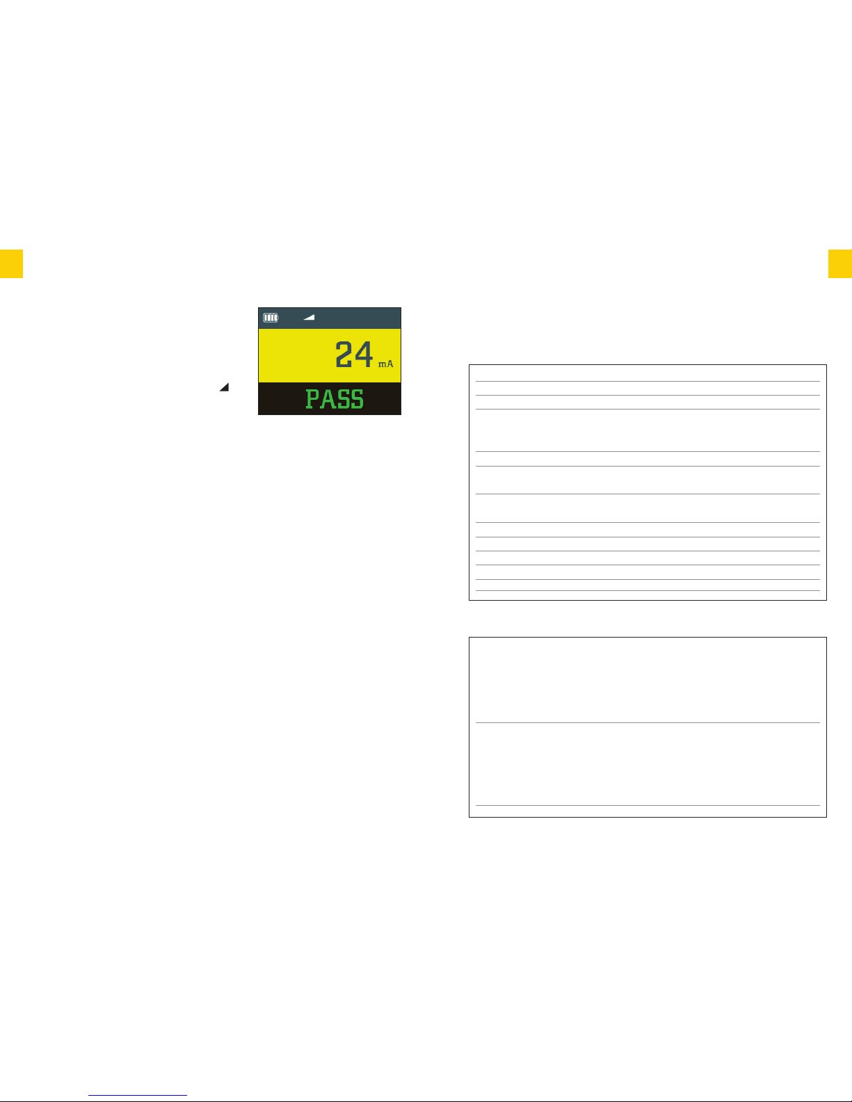
Use the rotary switch to select the rating of the RCD.
Press the RCD multiplier button until the symbol is
displayed.
Press the test button to start the test. The fault current
applied will increment in 3mA steps until the RCD trips.
If nuisance tripping on a circuit is a problem this function can be used to retest the RCD with
other appliances systematically connected and removed.
For example a 30mA RCD may trip at 12mA on ramp test with an appliance connected and
then at 27mA with the appliance removed. You will know that the appliance is leaking
approximately 15mA.
PPhhaassee rroottaattiioonn
Principle of Measurement
During phase rotation measurement the amplitudes and phase angles of the three inputs L1 L2
L3 are checked against limits, allowing for mild unbalance conditions.The indication 1-2-3 is
displayed for normal rotation (L2 lags L1) and 3-2-1 for reverse rotation (L2 leads L1).
Display of Phase rotation is Automatic when all three tests leads are connected to the 3 phase
supply as below:
Set the main rotary switch phase
Using three test leads, connect test leads to the L1 to Phase 1, L2 to Phase 2 and L3 to Phase
The Ethos 8400 will display .1 .2 .3 or .1 .3 .2 depending on the direction of phase rotation.
WARNING
Only use LR6 Alkaline replacement batteries.
Please dispose of your batteries carefully.
Batteries are made from important resources and chemicals,including lead, cadmium, zinc,
lithium and mercury. If batteries are disposed of as normal waste, they’ll be taken to a landfill
site and those resources will be lost and will contribute to the pollution of the environment.
Recycling is one way you can help the environment and you should dispose of used batteries
separately from other waste,using local collection
and recycling schemes available.
26
EETTHHOO SS 8844 0000
INSTRUCTION MANUAL
Page 15
29
EETTHHOO SS 8844 0000
INSTRUCTION MANUAL
28
EETTHHOO SS 8844 0000
INSTRUCTION MANUAL
EETTHHOO SS 8844 0000
INSTRUCTION MANUAL
AAccccuurraaccyy aatt AApppplliieedd TTeesstt CCuurrrreenntt
TEST CURRENT ACCURACY
1/2 +0% -10%
x 1 +10% -0%
x5 (30mA only) +10% -0%
(Ramp) ± 5% of rated I
N
Ramp Characteristics: 20% to 110% of rated IN in 10% steps (300ms dwell time)
OOppeerraattiinngg RRaannggeess aanndd UUnncceerrttaaiinnttiieess AAccccoorrddiinngg ttoo EENN 6611555577
FUNCTION DISPLAY EN 61557 EN 61557 OPERATING NOMINAL
RANGE MEASUREMENT RANGE UNCERTAINTY VALUES
Insulation 0.001 MΩ 0.1MΩ 1.6% UN= 250/500/1000
Resistance -1000MΩ –1000MΩ V
DC I
N
= 1.0 mA
EN 61557-2
Loop 0.01Ω 1.04Ω-470Ω Hi-I: 4.8% UN= 230/400VAC
Impedanc e -500Ω No-Trip: 10.8% f = 50/60Hz
EN 61557-3
Continuity 0.00Ω 0.1Ω-10kΩ 12% 4.0VDC
EN 61557-4 –20kΩ <UQ <24VDC
RLO2.00Ω
I
N
>
200 mA
RCD
UU
T : 5ms–UUT : 38.2ms –UUT : 2.8% I
UU
N
= 30/100/300
EN 61557-6 2000ms 214.8ms /500 mA
I
UU
N
- I
UU
N
: 15mA–500mA I
UU
N
: 7.2%
Specification
EETTHHOO SS 8844 0000
INSTRUCTION MANUAL
RRCCDD
SYSTEM VOLTAGE SYSTEM VOLTAGE NOMINAL FAULT / TOUCH TRIP OVER VOLTAGE PROTECTION
RANGE FREQUENCY CURRENTS (MA) ACCURACY TIME (BS EN 61557-10)
195–253VAC 50-60Hz 30, 100, 50V ±(1% 550V
300, 500 + 1ms)
CCoonnttiinnuuiittyy
MEASUREMENT ACCURACY OPEN SHORT CIRCUIT MAX LEAD NULL OVER VOLTAGE
RANGE CIRCUIT CURRENT (AT 2Ω)RESISTANCE PROTECTION
0.00Ω to ±(3% > 4 V > 200mA 4Ω 550V Fused
19.99 kΩ +2 digits) <10 V
OOuuttppuutt VVoollttaaggee
VOLTAGE LOAD ACCURACY OUTPUT CURRENT SHORT CIRCUIT
CURRENT(INTO 2KΩ)
250 V 250kΩ -0% +20% 1 mA <2 mA
500 V 500kΩ -0% +20% 1 mA < 2 mA
1000 V 1MΩ -0% +20% 1 mA < 2 mA
IInnssuullaattiioonn
TEST VOLTAGE MEASUREMENT ACCURACY SHORT CIRCUIT OVER VOLTAGE PROTECTION
RANGE CURRENT (INTO 2KΩ) (BS EN 61557-10)
250V 0.001 to ±(3% <2 mA 550V
200.0MΩ +2 digits +10%/GΩ)
500V 0.001 to ±(3% <2 mA 550V
500.0MΩ +2 digits +5%/GΩ)
1000V 0.001 to ±(3% <2 mA 550V
1000MΩ +2digits +2.5%/GΩ)
Specification
Page 16

LLIIMMIITTEEDD WWAARRRRAANNTTYY AANNDD LLIIMMIITTAATTIIOONN OOFF LLIIAABBIILLIITTYY
The Ethos 8400 is warranted to be free from defects in material and workmanship under
normal use and service.The warranty period is three years and begins on the date of purchase.
Parts, product repairs, and services are warranted for 90 days. This warranty extends only to the
original buyer/end user customer of an Ethos authorised reseller, and does not apply to fuses,
disposable batteries, or to any product which, in Ethos opinion, has been misused, altered,
neglected, contaminated, or damaged by accident or abnormal conditions of operation or
handling.
Ethos authorised resellers shall extend this warranty on new and unused products to end user
customers only but have no authority to extend a greater or different warranty on behalf of
Ethos. Warranty support is available only if the product is purchased through an Ethos
authorised sales outlet.
The Ethos warranty obligation is limited: Ethos have the option to repair the product free of
charge, replace a defective product, or refund the purchase price which is returned to an Ethos
authorised service centre within the warranty period.
To obtain warranty service contact your nearest Ethos service centre to obtain return
authorisation information then return the product to that service centre with a description of
fault. Following warranty repair the product will be returned to the authorised centre and in
turn they will return the repaired product back to the end user. If Ethos determines that failure
was caused by neglect, misuse, contamination, alteration,accident, or abnormal condition of
operation or handling, including overvoltage failures caused by outside the products specified
rating, or normal wear and tear of mechanical components, Ethos will provide an estimate of
repair and obtain authorisation before commencing the work.
This warranty is buyers sole and exclusive remedy and is in lieu of all other warranties, express
or implied, including but not limited to any implied warranty of merchantability or fitness for a
particular purpose. Ethos shall not be liable for any special, indirect, incidental or consequential
damages or losses.
Ethos Instruments
Distributed by MTi
Victoria Road
Avonmouth
Bristol
BS11 9DB
Tel: 0117 938 6400
Fax: 0117 923 5374
Email: [email protected]
Web: www.ethos-instruments.co.uk
31
EETTHHOO SS 8844 0000
INSTRUCTION MANUAL
30
EETTHHOO SS 8844 0000
INSTRUCTION MANUAL
OOppeerraattiinngg UUnncceerrttaaiinnttiieess
INFLUENCE INSULATION LOOP IMPEDANCE CONTINUITY RCD RCD
Q
UANTITY RESISTANCE Z
I
R
LO
UU
TI
UU
N
R
ISO
EN 61557-2 EN 61557-3 EN 61557-4 EN 61557-6 EN61557-6
A – Intrinsic
Uncertainty 0.8% 0.9% 1% 1.5% 5.6%
E1– Position 0% 0% 0% 0% 0%
E2– Supply Voltage 1.0% 0.8% 10% 1.2% 0.3%
E3- Temperature 0.8% 4.9% 0.7% 2.0% 2.1%
E6– System Phase Angle - 2.4% - - E7– System Frequency - 0.4% - - E8– System Voltage - 1.4% - 1.5% 0.6%
E9– System Harmonics - 0.8% - - E10– System D.C Quantities- 8.4% - - -
Specification
 Loading...