

Ethos 36C, 54C Installation And Operating Manual
ETHOS 36C and 54C
CONDENSING COMBINATION BOILER
Installation and Operating Manual
1511/05 Issue 1

Installation and Operation manual ETHOS 36C and ETHOS 54C –1511/05-issue1
Page 1
INDEX
1 SAFETY GUIDELINES.............................1
1.1 Conditions.....................................................1
1.2 General guidelines .........................................1
2 TECHNICAL DATA ...................................2
2.1 Front view .....................................................2
2.2 Explanation of parts ......................................3
2.3 Technical data................................................4
2.4 Introduction...................................................5
2.5 Operation of ETHOS Boiler..........................5
2.6 Control ..........................................................5
2.7 Combustion products.....................................5
2.8 Variable fan ...................................................5
2.9 On/off pump..................................................5
2.10 Description of appliance................................5
2.11 Ethos …C......................................................5
3 INSTALLATION.........................................6
3.1 Unpacking.....................................................6
3.2 Selecting a location in the house...................6
3.3 Suspending the appliance..............................6
3.4 Flue System ...................................................7
3.5 Supply and discharge system.........................7
3.6 Influence of flue system on heat input ..........7
3.7 Classification according to evacuation of
combustion products .....................................8
3.8 Ethos resistance table ....................................9
3.9 Condensate discharge..................................10
3.10 CH and DHW circuit...................................10
3.10.1 Attention! Important....................................10
3.10.2 CH circuit....................................................10
3.10.3 Expansion Vessel.........................................10
3.10.4 Main Cold Water Inlet.................................10
3.11 Pump circuit ................................................11
3.11.1 On/off pump ................................................ 11
3.12 Frost protection ...........................................11
3.13 Connecting the gas pipe .............................. 11
4 ASSEMBLY INSTRUCTIONS FOR
ELECTRICIAN.........................................12
4.1 Mains connection........................................12
4.2 Terminal block connections.........................12
4.3 Wiring diagram............................................13
5 OPERATION.............................................14
5.1 Display........................................................14
5.2 Diagnosis mode display ..............................14
5.2.1 Control buttons ............................................14
5.3 Sensors........................................................15
5.4 Installer programme ....................................17
5.5 Explanation of options for installer.............17
5.5.1 Programme number J1: Max. CH supply
temperature..................................................17
5.5.2 Programme number J2: Max. CH heat output
(fan speed during CH mode)....................... 17
5.5.3 Programme number J3: Pump operation.....17
5.5.4 Programme number J4: Pump CH overrun
time..............................................................17
5.5.5 Programme number J5: Pump DHW overrun
time..............................................................17
5.5.6 Programme number J6: Step modulation
Control ........................................................18
5.5.7 Programme number J7: Hot water
temperature..................................................18
5.5.8 Programme number J8: Max. DHW output.19
5.6 Filling and bleeding the boiler and
installation...................................................19
5.7 Starting the appliance..................................21
5.7.1 General........................................................21
5.7.2 First commissioning....................................21
5.8 Heat input adjustment and setting ...............21
5.8.1 Max. heat input setting................................21
5.8.2 CO2 settings..............................................21
5.8.3 Checking the max CH input........................21
5.8.4 Min. input setting........................................22
5.9 Conversion for different gas type................22
5.10 DHW temperature.......................................22
5.11 Shutting down .............................................22
6 FAILURES.................................................23
6.1 Cause of failure ...........................................24
6.2 Table of solutions........................................26
7 MAINTENANCE......................................28
7.1 General........................................................28
7.2 Inspection....................................................28
7.3 Maintenance................................................29
8 USER INSTRUCTIONS........................... 30
9 EXPLODED VIEW...................................31
10 PARTS LIST..............................................32

Installation and Operation manual ETHOS 36C and ETHOS 54C –1511/05-issue1
Page 1
1 SAFETY GUIDELINES
1.1 Conditions
ETHOS BOILERS shall not be liable for any damages caused by non-compliance with the assembly instructions.
Only original ETHOS parts must be used for service purposes.
1.2 General guidelines
It is a statutory requirement that all gas appliances are installed in accordance with the manufactures instructions and
all current regulations in force, all instructions should be fully read before installing or using the appliance.
All installations should be carried out by competent persons as described in the Gas Safety (Installation & Use)
Regulations. i.e. CORGI registered and holding current certification.
The work must be carried out by a competent person as described in the I.S. 813 Domestic Gas Installations with
reference to the following codes of practices.
The Manufacturers instructions MUST NOT be taken in any way as overriding statutory obligations.
This boiler has been tested and certified to comply with all necessary European directives, latest building regulations
and efficiency requirements for the SEDBUK scheme and as been approved with an efficiency band rating of A and
is CE marked and complies with
92/42/EEC Efficiency of Hot Water Boilers Directive
90/396/EEC Gas Appliance Directive
93/68/EEC Low Voltage Directive (was 73/23)
92/31/EEC Electromagnetic compatibility Directive
I.S. 813 Domestic Gas Installations
The boiler should be installed in compliance with
The building regulations (Scotland-consolidated)
Building Regulations (Northern Ireland)
Building Regulations
Water fittings regulations or water bylaws in Scotland
Local water company bylaws
The boiler should not be modified in any way. Any modifications will invalidate the gas approval and invalidate the
warranty.
Codes of Practice
BS 7593:1992 Treatment of water in domestic hot water central heating systems
BS5546:1990 installation of hat water supplies for domestic purposes
BS5440 part 1: 2000 flues
BS5440 part 2: 2000 Ventilation
BS5449:1990 Forced circulation hot water systems
BS6798:2000 installation of gas fired hot water boilers of rated inputs not exceeding 70kW
BS6891:1989 Installation of low pressure gas pipe up to 28mm
BS7671:2001 IEE wiring regulations
BS4814:1990 Specification for expansion vessels
BS5482:1994 installation of LPG
BS7671 requirements for electrical installations
BS5955 -8 plastic pipe work installations
ATTENTION: High Voltage
Before opening the boiler casing for maintenance or servicing the 230VAC main supply to the boiler must be
disconnected!!
Installation and Operation manual ETHOS 36C and ETHOS 54C –1511/05-issue1
Page 2
126 50 50 50 50 89 37
5755250
125
350
106 120 120 106
452
55
1 + 9 2 3 4 5 6 78 10
11
13
12
14
2 TECHNICAL DATA
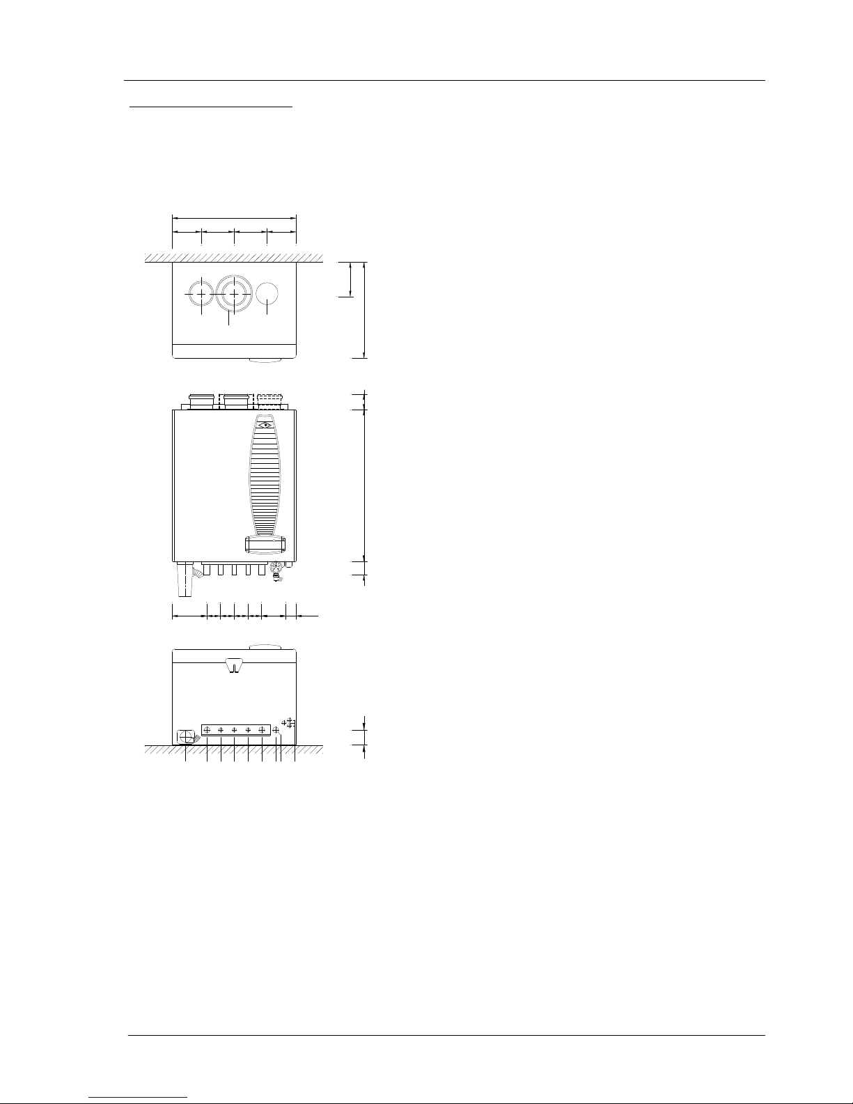
2.1 Front view
Figure 1 Dimensional sketch of CH boiler connections
1 = Condensate Trap
2 = CH Flow connection 22mm
3 = DHW Flow connection 15mm
4 = Gas connection 15mm
5 = MCW connection 15mm
6 = CH return connection 22mm
7 = Drain cock
8 = Pressure gauge
9 = Condensate discharge
10 = Cable glands (3x)
11 = Air supply (alternative 80mm 2 pipe)
12 = Air supply, concentric
13 = Flue discharge
14 = Air supply (alternative 80mm 2 pipe)
Installation and Operation manual ETHOS 36C and ETHOS 54C –1511/05-issue1
Page 3
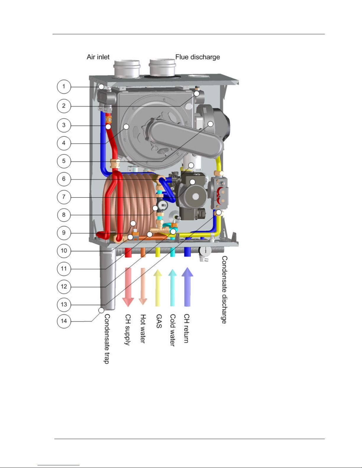
2.2 Explanation of parts
1 = heat exchanger bleed valve
2 = high limit thermostat
3 = supply sensor
4 = heat exchanger
5 = fan
6 = air vessel
7 = circulation pump
8 = flow sensor
9 = DHW coil
10 = DHW sensor
11 = DHW adjusting cock
12 = Mains cold water sensor
13 = gas control valve
14 = Condensate trap
Installation and Operation manual ETHOS 36C and ETHOS 54C –1511/05-issue1
Page 4
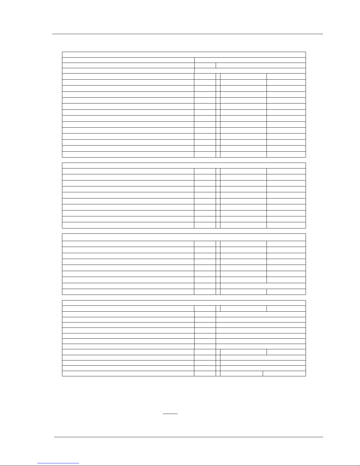
2.3 Technical data
General
EC product ID number CE 0063 BQ 3034 (2005)
Dimensions (HxWxD) mm 550 x 450 x 350
Category II2L3P
Type of appliance
Ethos 36C
Ethos 54C
CH water content of appliance litre
2,1 2,7
CH water content of tap water heat exchanger litre
1,5 1,5
Weight (empty) kg
37 41
CH supply/return connections mm
22 22
Gas connections mm
15 15
Domestic water, hot/cold mm
15 15
Flue connection mm
80 80
Air supply mm
80 80
Concentric mm
80/125 80/125
Power consumption W
180 200
Power consumption, partial heat input W
100 135
Power consumption, standby W
5 5
IP-classification
IP44 IP44
Central heating
Nominal Heat Input (net) kW
6,6 – 28,5 9,9 – 38,7
Nominal Heat Input (gross) kW
7,3 – 31,7 11,0 – 43,0
Max. gas consumption m³/uur
3,0 4,1
Efficiency at 50/30°C, full heat input %
105,0 105,4
Efficiency at 50/30°C, partial heat input %
108,1 108,5
Nominal heat output at 80/60°C kW
6,3 – 27,6 9,6– 37,5
Nominal heat output at 50/30°C kW
7,1 – 29,9 10,7– 40,8
Sedbuk rate
A A
NOx-emission mg/kWh
<15 <15
CO- emission mg/kWh
<20 <20
Domestic hot water
Nominal Heat Input (net) kW
6,6 – 36,0 9,9 – 54,0
Nominal Heat Input (gross) kW
7,3 – 40,0 11,0 – 60,0
Max. gas consumption m3/uur
3,7 5,6
DHW flow rate at 60°C (∆T=50K)
l/min
10 ** 15 **
DHW flow rate at 40°C (∆T=30K)
l/min
16 ** 25 **
Sanitary pressure loss, at 7,5 l/min DHW flow bar
0,25 0,25
Sanitary pressure loss, at max. DHW flow (∆T=50K)
bar
0,38 0,85
WRAS approval number
0204111
Domestic hot water (fixed setting) °C
60 60
Technical data
Max. flue gas volume m3/uur
50,4
75,6
Boiler class (evacuation /air supply) B23, C13, C33, C43, C53, C63, C83
Flue gas CO2 content % 9
Flue gas dew point °C 52
Flue temperature at 80/60°C (at ambient temperature of 20°C) °C 75
Flue material temperature class T 120
Permitted maximum resistance of flue system * Pa 150*
Condensation pH value 4 tot 5,5
Available CH pump pressure at ∆T20°C (in meter Water Gauge)
mWG
2,0 1,5
Max. CH supply temperature °C 90
CH water pressure (min./max.) bar 0,5 – 3
Sanitary water pressure (min./max.) bar 2 - 10
NOx class 5 5
* With this resistance value the heat input will stay within the specifications indicated on the data plate; if the
resistance is higher, the heat input will drop, see par3.6.
** At an initial pressure of 2 bar.
Table 1 Specifications

Installation and Operation manual ETHOS 36C and ETHOS 54C –1511/05-issue1
Page 5
2.4 Introduction
This Installation and Operating manual is for the installer and the user of the ETHOS boiler.
It contains essential information for installing and adjusting ETHOS boilers. We recommend that you first consult this
installation manual, to ensure that the installation is carried out correctly. In addition, it is required that the end user of the
boiler be fully instructed on how it operation, and that the installation and operation manual be left near the boiler to make
it immediately available for later use, if necessary.
2.5 Operation of ETHOS Boiler
This ETHOS; is a high efficiency, condensing, combination Boiler. Flues are cooled below condensation point by a
Spiranox heat exchanger made of stainless steel. This produces an additional heat which will contribute to the boiler
efficiency, which is in excess of 107%. The European calculation method assumes 100% efficiency for appliances
which do not condense and efficiencies higher than 100% for condensing appliances.
Since flue gases are very low in temperature (lower than 75°C), a stainless steel or PP plastic approved flue pipe
must be used.
The appliance is manufactured in according with the European approved requirements (EC) and has the following
Dutch Gastec Gaskeur quality marks: Clean combustion (SV) – 107% High Efficiency (HR) – Comfort Hot Water
(CW) –,High Efficiency Hot Water (HRww) and – Solar Boiler Reheater (NZ).
2.6 Control
The boiler can be controlled using a conventional volt free time clock, room thermostat or by a modulating
OpenTherm® room thermostat.
The boiler is fully modulating to help maintain a constant heat temperature both in the house and for the hot water
production temperature.
2.7 Combustion products
Due to the modulating premix burner, the combustion complies with the strictest European standards.
2.8 Variable fan
A speed-controlled fan is used to reduce power consumption: when the heat requirement is low, the fan will rotate
more slowly, resulting in lower power consumption.
2.9 On/off pump
The appliance has a pump with speed switch. (Attention! Do not use on position 1).
2.10 Description of appliance
The appliance is a combination boiler suitable for Domestic Hot Water (DHW) production and Central Heating
installation.
The boilers are range rateable. The maximum heat output can be set and adjusted to the requested heat output of the
central heating.
2.11 Ethos …C
This appliance has a built-in low water content DHW heat exchanger spiral for hot water production. All
connections are internal, while a flow restrictor provides a maximum hot water flow with a DHW temperature of
approx. 60°C (table 3, page 10).
The tap water temperature is set to 60°C to prevent Legionella contamination.
Note: The 54C boiler has no flow restrictor fitted.
Installation and Operation manual ETHOS 36C and ETHOS 54C –1511/05-issue1
Page 6
3 INSTALLATION
3.1 Unpacking
This appliance is supplied with:
• Installation and Operating manual;
• a user manual with warranty card;
• a bleed key;
• a hanging bracket;
• Condensation trap with condensate discharge hose.
Check the appliance immediately on receipt.
Any damages must be reported to the supplier immediately.
All appliances are completely assembled.
Ethos combination boilers are adapted to natural gas G20
3.2 Selecting a location in the house
The front and bottom side of the appliance have to be accessible
for maintenance and service.
Both sides must be placed at least 20 mm from the wall or cabinet wall.
The following facilities must be present at the assembly location:
a) A permanent 230 volt single phase power supply with the boiler being
protected by a double pole switch with minimum openings of 3mm
and fused at 3 amps.
b) Drain connection suitable for condensate discharge.
c) Wall which can support the boiler weight.
The assembly location should be dry and protected from unsuitable weather
conditions such as frost and freezing.
The appliance has a built-in fan which will cause a small degree of noise depending
on the heat input: choose a location in the house where this sound production will
not cause nuisance, preferably against a brick wall.
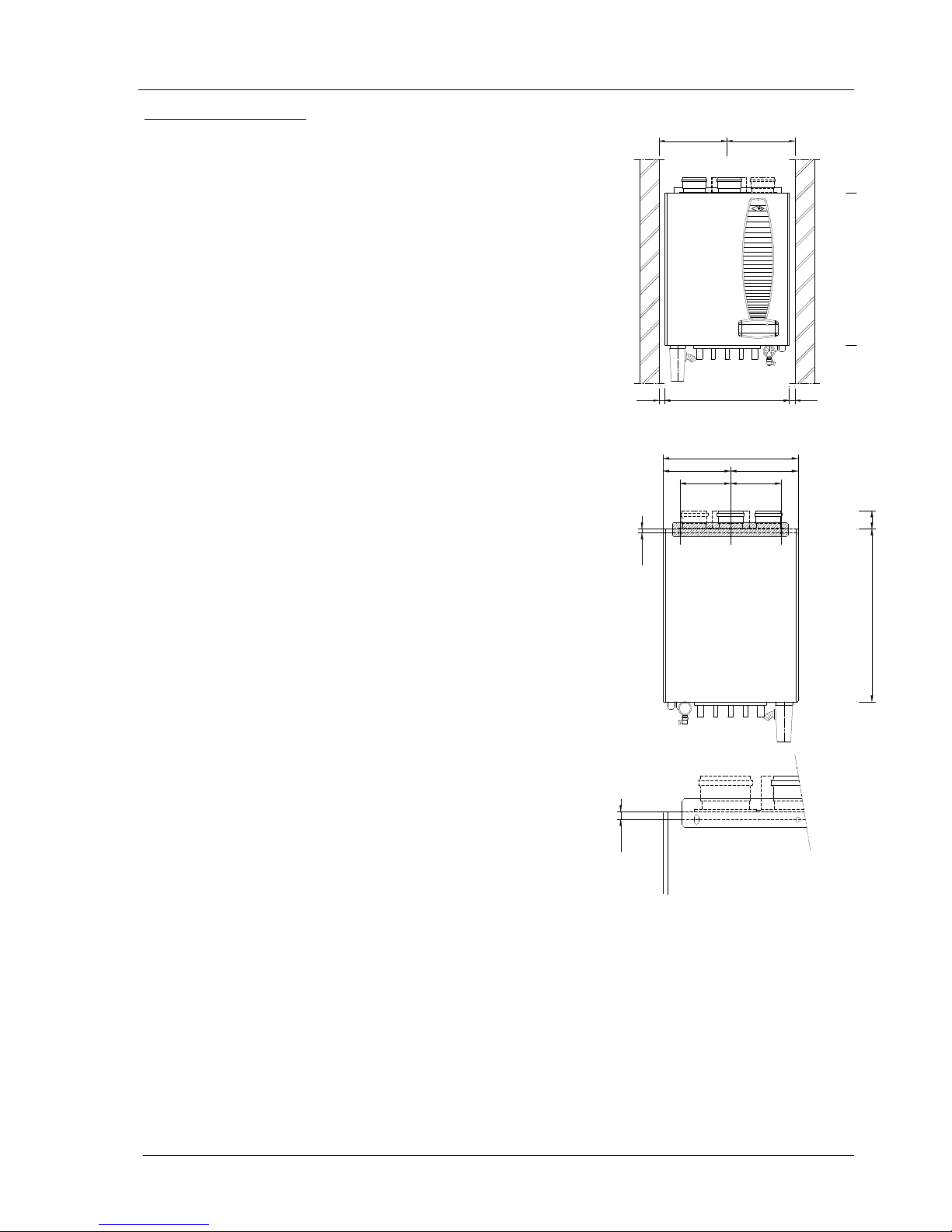
3.3 Suspending the appliance
Mark off the holes for the hanging bracket and determine the location for
connecting the supply and discharge pipes.
Figure 2 Dimensional sketch of clearances
Figure 3 Dimensional sketch of wall bracket
552 57
226
170170
12,5
Ø8
8x15 8x15
12,5
452
226
246
552
452 2020
246
Installation and Operation manual ETHOS 36C and ETHOS 54C –1511/05-issue1
Page 7
20
25
30
35
40
45
50
55
60
0 50 100 150 200 250 300 350 400 450 500
Pressure drop [Pa]
DHW heat input (Net) [kW]
36C
54C
3.4 Flue System
General
Air supply material: PP plastic or stainless steel
Flue discharge material: plastic (temperature resistant up to 120° C, air flushed) or stainless steel
Attention!
First connect all pipes and fill up and bleed the installation before commissioning the boiler.
The high flue gas temperature protection for plastic discharge material is built into the boiler as a safety feature. This
protection cuts off the gas supply as soon as the flue temperature gets too high, after which the appliance is
interlocked and error code 't0' starts to flash.
There are two types of connections:
• Concentric connection (80mm / 125mm with one pipe inside the other)
• Two Pipe system (80mm air intake with a separate 80mm Flue outlet)
Concentric connection (standard)
The concentric connection kit is standard: diameter air supply pipe 125 mm and flue pipe 80 mm.
Always place the plastic supply connection on top of the air inlet connection.
Two Pipe System (optional)
The optimal connection for air supply and flue pipes is obtained by using a stainless steel or plastic discharge
system.
The connection diameter for the flue pipe is 80 mm and for the air supply pipe also 80 mm.
The air supply pipe can be placed on the left or right side of the flue pipe by moving the connecting tube
3.5 Supply and discharge system
The Ethos boiler is a room sealed appliance with the air needed for combustion being drawn in from outside. The
casing jacket is sealed airtight to the back plate, so air can only be supplied through the air supply pipe. Therefore,
always make sure that the front door is placed on the appliance when the boiler is operating.
Attention!
Note that any horizontal flue pipe must be sloped back toward the boiler at a rate of 10mm per 1 metre. If not,
condensation can accumulate in the flue pipe, and may result in water damage to the boiler.
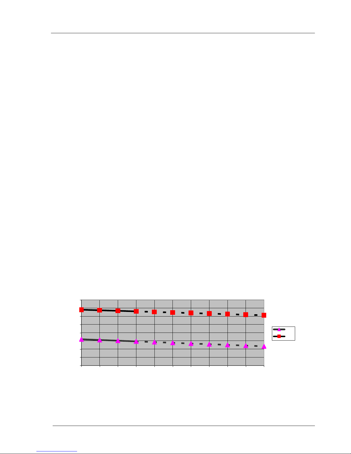
3.6 Influence of flue system on heat input
The diagram shows the ratio between the kW input and the flue systems resistance. For the maximum
Boiler output a resistance of 150 Pa or less is used.
Should the flue resistance be more than 150Pa the boilers output will be reduced; of further information contact the
technical department.
Diagram 1 influence of pressure loss on heat input
DHW heat input (Net) [kW]
Installation and Operation manual ETHOS 36C and ETHOS 54C –1511/05-issue1
Page 8
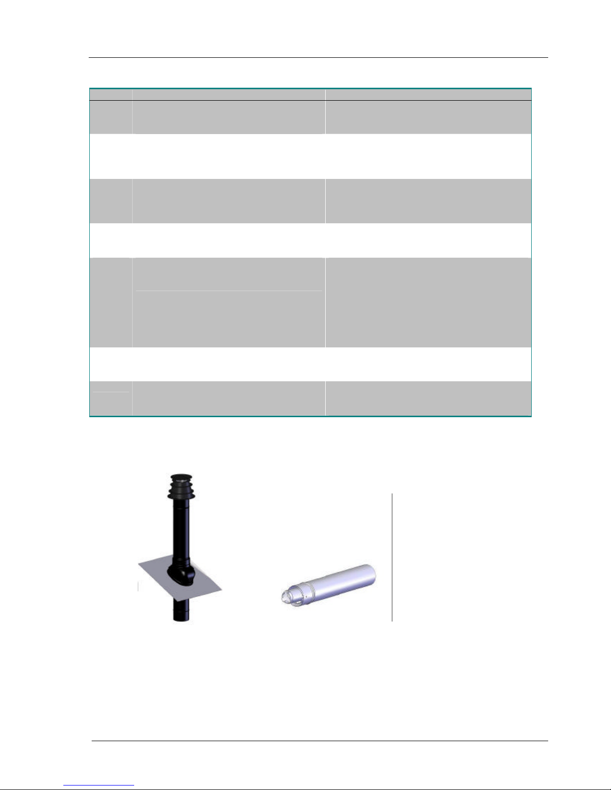
3.7 Classification according to evacuation of combustion products
Class System description Comments:
B23
• Non-room sealed application; flue connected
to outside but combustion air is being drawn
directly from room where boiler is installed.
• Appliance complies with Class C
• Max. back pressure 1mbar (100Pa)
C13
• Room sealed premix appliance with
horizontal outlet
• Air intake and flue gas discharge through
concentric exterior wall terminal
• Type exterior wall duct
• Max. resistance 150 Pa
• Ducts sloped to drain toward boiler (1cm/m)
C33
• Room sealed premix appliance with vertical
outlet terminal
• Air intake and flue gas discharge through
concentric exterior roof terminal
• Type roof duct
• Max. resistance 150Pa
C43
• Room sealed premix appliance with
collective supply and discharge
• Max. resistance 150Pa
• Ducts sloped to drain toward boiler (1cm/m)
• Collective discharge with under pressure
C53
• Room sealed premix appliance with separate
supply from exterior wall and separate
discharge through roof
• Air terminal not provided by boiler
manufacturer
• Roof terminal not provided by boiler
manufacturer
• Max. resistance 150Pa
• Ducts sloped to drain toward boiler (1cm/m)
• Supply and discharge to be installed on the
same side of the building
C63
• Room sealed premix appliance with separate
approved and marketed system
• Only connect to UK approved discharge
material
• Max resistance 150Pa
C83
• Room sealed premix appliance with separate
supply from exterior wall and collective
discharge
• Type exterior wall duct not provided
• Max. resistance 150Pa
• Ducts sloped to drain toward boiler (1cm/m)
Vertical terminal Horizontal terminaL
Installation and Operation manual ETHOS 36C and ETHOS 54C –1511/05-issue1
Page 9
3.8 Ethos resistance table
By using different flue installations, either concentric or the 2 pipe system different flue lengths can be achieved, Up
to a resistance of 150 Pa. At this pressure the heat input will be equal (±5%) to the heat input specified on the data
plate of the appliance. In case a concentric system is used, its length should not exceed 12 meters.
Example of calculation
boiler type: Ethos 54C
Concentric pipe 80/125mm vertical 5m + horizontal 1m=total 6m concentric straight pipe
2x Concentric 90° bend ;
2x Concentric 45° bend ;
Vertical terminal 80/125.
Resistance
Concentric pipe 80/125: 6m 6 x 11,3 67,8 Pa
Concentric 90° bends : 1 pieces 1 x 12,4 12,4 Pa
Concentric 45° bends : 2 pieces 2 x 8,4 16,8 Pa
Vertical terminal 80/125 40 Pa
Total Resistance 137,0 Pa
Total resistance is 137 Pa, so the boiler output is not changed by the resistance (lower than 150 Pa) and total
concentric length is less than maximum allowed 12 meters.
Concentric Flue System (mm) Resistance system [Pa]
Part
ETHOS 36 C ETHOS 54C
Vertical Terminal 80/125
19 40
Horizontal Terminal 80/125
36 75
straight pipe/m 80/125
5,3 11,3
45° bend 80/125
4,1 8,4
90° bend 80/125
6,1 12,4
Two Pipe System
Air Inlet Part
straight pipe/m
80
1,7 3,4
45° bend R=0,5D 80 2,0 3,8
90° bend R=1,0D 80 3,2 5,8
Flue Gas Outlet
Vertical terminal 80 19 40
Horizontal terminal 80 36 75
straight pipe/m
80 2,1 4,9
45° bend R=0,5D 80 2,5 5,8
90° bend R=1,0D 80 3,9 8,9
Table 3 Flue discharge resistance
 Loading...