


OPERATING INSTRUCTIONS
G
G
M
M
V
V
2
2
-
-
K
K
Microprocessor-Based Power Supply
Subject to change without prior notice
and Analyzing Unit
for Torque Transducers


ETH-messtechnik gmbh D-74415 Gschwend P.O. 16
3
Nr.: 162e Operating Instructions GMV2-K revised: 09.05.2019 Rev.: 0
Content
1 GENERAL INFORMATION ........................................................................................................................................ 6
1.1 COMPANY ADDRESS................................................................................................................................................... 6
1.2 DESCRIPTION ............................................................................................................................................................. 6
1.3 FEATURES .................................................................................................................................................................. 6
2 STARTUP ........................................................................................................................................................................ 6
2.1 IMPORTANT NOTES .................................................................................................................................................... 6
2.2 FRONT PANEL OF UNIT ............................................................................................................................................... 7
2.3 CONNECTIONS OVERVIEW.......................................................................................................................................... 8
2.4 CONNECTING THE TORQUE TRANSDUCER .................................................................................................................. 9
2.5 SWITCHING ON ........................................................................................................................................................... 9
2.6 SWITCHING OFF ......................................................................................................................................................... 9
3 WHAT'S NEW IN SOFTWARE VERSION V5.1 (AF TER V4.1) ........................................................................... 10
3.1 DYNAMIC REPEAT RATE FOR KEYS........................................................................................................................... 10
3.2 AUTOMATIC CONVERSION OF THE TRANSDUCER FULL SCALE VALUE TO OTHER UNITS ............................................ 10
3.3 SUPPORTING TRANSDUCERS WITH TWO MEASURING RANGES .................................................................................. 10
3.4 IMPROVED SUPPORT FOR A NUMBER OF INPUTS ....................................................................................................... 10
3.5 UNIVERSAL INPUT RANGE FOR THE ACTIVE AND PASSIVE INPUT .............................................................................. 10
3.6 ADJUSTABLE OVERLOAD RANGE.............................................................................................................................. 11
3.7 AUTOMATICALLY TRACKING ZERO-POINT DRIFT ..................................................................................................... 11
3.8 PULSE-TYPE SCREWDRIVER MODE ........................................................................................................................... 11
3.9 STREAMLINING PARAMETER SET ENTRY .................................................................................................................. 11
3.9.1 Defaults ........................................................................................................................................................... 11
3.9.2 Hiding unused functions ................................................................................................................................. 11
3.9.3 Correction factor ............................................................................................................................................ 12
3.9.4 Filter for peak measuring ............................................................................................................................... 12
3.10 DELETING MEASURED VALUES ................................................................................................................................ 12
3.11 DETECTING NEW TRANSDUCERS AND NEW MEASURING RANGES ............................................................................. 12
3.12 POWER-SAVING FUNCTION (STANDBY) .................................................................................................................... 12
3.13 CANCEL SERIAL TRANSMISSION ............................................................................................................................... 12
3.14 CONTINUOUS OUTPUT WITH A MINIMUM 0.5 SECOND INTERVAL PERIOD ................................................................. 12
3.15 ANALOG OUTPUT ..................................................................................................................................................... 12
3.16 BATTERY PROTECTION ............................................................................................................................................ 13
4 MENU STRUCTURE................................................................................................................................................... 13
4.1 INTRODUCTION ........................................................................................................................................................ 13
4.2 DIRECT FUNCTION KEYS .......................................................................................................................................... 13
4.3 MEASURE MENU ...................................................................................................................................................... 14
4.4 MENU: DELETE MEASURED VALUE .......................................................................................................................... 14
4.5 MENU: OUTPUT ....................................................................................................................................................... 14
4.6 PARAMETER MENU .................................................................................................................................................. 14
4.6.1 Transducer ...................................................................................................................................................... 14
4.6.2 Limits .............................................................................................................................................................. 15
4.6.3 Settings ............................................................................................................................................................ 16
4.6.4 Parameter set .................................................................................................................................................. 16
5 SETTINGS .................................................................................................................................................................... 16
5.1 FUNCTIONS .............................................................................................................................................................. 16
5.2 PASSWORD .............................................................................................................................................................. 16
5.3 INITIAL SETTINGS..................................................................................................................................................... 16
5.4 DEFAULTS ............................................................................................................................................................... 16
6 INITIAL SETTINGS .................................................................................................................................................... 17
6.1 LANGUAGE .............................................................................................................................................................. 17
6.2 TIME OF DAY AND DATE .......................................................................................................................................... 17
6.3 PRINTER (SERIAL INTERFACE) ................................................................................................................................. 17
6.4 USB2.0-INTERFACE ................................................................................................................................................ 17
Subject to change without prior notice

ETH-messtechnik gmbh D-74415 Gschwend P.O. 16
4
Nr.: 162e Operating Instructions GMV2-K revised: 09.05.2019 Rev.: 0
6.5 STANDBY (POWER-SAVING FUNCTION) .................................................................................................................... 17
6.6 DISPLAY ILLUMINATION .......................................................................................................................................... 18
6.7 CONTRAST OF DISPLAY ........................................................................................................................................... 18
7 MEASURING MODES ............................................................................................................................................... 18
7.1 TRACKING MEASUREMENTS .................................................................................................................................... 18
7.2 FILTER ..................................................................................................................................................................... 18
7.3 OUTPUTTING MEASURED VALUES CONTINUOUSLY .................................................................................................. 18
7.4 SPEED MEASUREMENTS ........................................................................................................................................... 19
7.5 POWER MEASUREMENT ........................................................................................................................................... 19
7.6 PEAK MEASURING ................................................................................................................................................... 19
7.7 TORQUE WRENCH MEASUREMENTS ......................................................................................................................... 19
8 THE ENTRY EDITOR ................................................................................................................................................ 20
8.1 INTRODUCTION........................................................................................................................................................ 20
8.2 SELECT SETTINGS .................................................................................................................................................... 20
8.3 ENTERING NUMBERS ............................................................................................................................................... 20
8.4 TRANSDUCER FULL SCALE VALUE ........................................................................................................................... 20
8.5 ALPHANUMERIC TEXTS ........................................................................................................................................... 21
9 THE PARAMET ER SET ............................................................................................................................................ 21
9.1 INTRODUCTION........................................................................................................................................................ 21
9.2 DESCRIPTION TEXT FOR PARAMETER SETS .............................................................................................................. 21
9.3 PARAMETER SET "0" ................................................................................................................................................ 21
9.4 PARAMETER SET DISPLAY ....................................................................................................................................... 22
9.5 PRINTOUT OF THE PARAMETER SET ........................................................................................................................ 22
9.6 SELECTION .............................................................................................................................................................. 23
9.7 CREATE NEW ........................................................................................................................................................... 23
9.8 EDITING .................................................................................................................................................................. 23
9.9 ERASE ..................................................................................................................................................................... 26
10 SCREWING TECHNOLOGY ................................................................................................................................ 27
10.1 TIME-BASED SEQUENCE DIAGRAM ......................................................................................................................... 27
10.2 TIMING .................................................................................................................................................................... 27
10.3 ANGLE .................................................................................................................................................................... 28
11 STORING MEASURED VALUES ......................................................................................................................... 28
11.1 THE MEASURED-VALUE STORAGE ........................................................................................................................... 28
11.2 THE DATA RECORD .................................................................................................................................................. 28
11.3 MEMORY SETTINGS................................................................................................................................................. 28
11.4 DISPLAYING THE STORED MEASURED VALUES ........................................................................................................ 29
11.5 DELETE MEASURED VALUES .................................................................................................................................... 29
12 PRINTING OUT THE STORED MEASURED VA LUES ................................................................................... 30
13 OPTIONAL FUNCTIONS ...................................................................................................................................... 31
13.1 BATTERY OPERATION .............................................................................................................................................. 31
13.2 PASSIVE INPUT ........................................................................................................................................................ 31
13.3 DIGITAL INPUT ........................................................................................................................................................ 31
13.4 MEASURED-VALUE TRANSMISSION GMV2-K PC ............................................................................................... 31
13.4.1 FUNCTION ........................................................................................................................................................... 31
13.4.2 MENU BAR .......................................................................................................................................................... 31
13.4.3 DATA TRANSM ISSION .......................................................................................................................................... 31
13.4.4 MEASURED-VALUE TABLE .................................................................................................................................. 32
13.4.5 STATISTIC AL ANALYSIS ....................................................................................................................................... 32
13.4.6 MEASURED-VALUE DIAGRAM .............................................................................................................................. 32
13.4.7 TORQUE WRENCH DOCUMENT ............................................................................................................................. 32
13.4.8 GENERAL INFORMATION ..................................................................................................................................... 33
13.5 INPUTS / OUTPUTS ................................................................................................................................................... 33
13.6 SHUTDOWN FOR ELECTRIC SCREWDRIVERS ............................................................................................................. 33
13.7 SHUTDOWN OF HYDRAULIC UNIT ............................................................................................................................ 33
13.8 OK OUTPUT ............................................................................................................................................................. 33
13.9 NOK OUTPUT .......................................................................................................................................................... 33
13.10 ANALOG OUTPUT ................................................................................................................................................ 33
Subject to change without prior notice

ETH-messtechnik gmbh D-74415 Gschwend P.O. 16
5
Nr.: 162e Operating Instructions GMV2-K revised: 09.05.2019 Rev.: 0
13.11 EXTERNAL CONTROL ........................................................................................................................................... 34
13.11.1 Zeroadjust ................................................................................................................................................... 34
13.11.2 Storing / Printing / Erasing ......................................................................................................................... 34
13.12 MEASURED-VALUE PRINTOUT TO THE DIGIMATIC DP-1 HS ................................................................................ 34
13.12.1 Introduction ................................................................................................................................................ 34
13.12.2 Connection and preparation ....................................................................................................................... 34
13.12.3 Transmission of limits ................................................................................................................................. 35
13.12.4 Printing out the measured values ................................................................................................................ 35
14 ERROR MESSAGES ............................................................................................................................................... 35
14.1 GENERAL ................................................................................................................................................................. 35
14.2 FAULTS AND THEIR CAUSES ..................................................................................................................................... 36
15 PIN ASSIGNMENTS ............................................................................................................................................... 37
11 DISPOSAL CONSIDERATIONS ........................................................................................................................... 38
12 OVERVIEW OF THE GMV2-K V5.1 MENU STRUCTURE ............................................................................. 39
Subject to change without prior notice

ETH-messtechnik gmbh D-74415 Gschwend P.O. 16
6
Nr.: 162e Operating Instructions GMV2-K revised: 09.05.2019 Rev.: 0
1 General information
1.1 Company address
ETH Messtechnik GmbH, Hagstr. 10, 74417 Gschwend, Germany
1.2 Description
GMV2-K is a microprocessor-based measuring, control and analyzing unit for the most common screwing and laboratory
applications. Due to its compact design and optional battery operation, the unit is very suited for portable use. Measured
values can be stored and printed out with date and time of day. The power-operated screwdriver can be automatically
switched off with separate power circuitry.
1.3 Features
• Menu-assisted operation and setting
• Recording torque, angle of rotation, speed and power
• For torque transducers from 1 Ncm to 100 kNm full scale value
• Shut off according to torque and/or angle of rotation (optional)
• 1000 measured-value storage
• 50 parameter set storage
• Mains operation (100V – 240V) or optional integrated charger, 8-hour battery operation.
• RS-232 port for printer
• Measured-data transmission to PC
• EMC sealed housing
2 Startup
2.1 Important notes
If the unit is opened or dismounted within the warranty period the warranty will be rendered null and void.
The unit should only be opened by qualified staff.
Only cables designed for use with the unit may be connected to it. Damage caused by connecting incorrect cables are not
covered by the warranty.
In battery operation, operation of the electric screwdriver is not possible!
The unit is not grounded during battery operation. Should current-carrying equipment be connected to the unit they must be
grounded according to technical regulations.
The full scale value displayed on the screen must always correspond with the actual transducer being used.
Where there is a risk of injury to persons and damage to equipment, the user must take appropriate safety measures (for
example, use covers, overload protection devices) (relevant accident prevention regulations should be observed!).
Due to the use of surge arresters (Varistors) an Insulation measurement according VDE 701/702 is not possible.
Please use the substitute leakage current measurement method according VDE 701/702.
The unit is not approved for service in hazardous areas.
Subject to change without prior notice

ETH-messtechnik gmbh D-74415 Gschwend P.O. 16
7
E1 < CW peak A SR : 995
↓ 8,10
P: 1 ST : 5 DR : 1 10 Nm
Zeroadj
Test
Menu
NIO ↓ 12 Grad
Error:
Charg
90%
Op no:
<Engine block-K> ID no 1234-03
ON/
OFF
Return
The four
menu keys
Key without
function
Transducer full
Torque
Angle of rotation or speed
Parameter set
number
Field for
error messages
Data
Memory number
Mode
direct function
direct function
Transducer Test
Menu tree selection
Remaining store
(number of free memory
Assessment of angle
Assessment of torque
Overall assessment
Peak status
Password level
Correction factor or filter
time
Parameter set
text
Operator no.
ID text
for data records
Automatic tracking of zero-point drift
Nr.: 162e Operating Instructions GMV2-K revised: 09.05.2019 Rev.: 0
2.2 Front panel of unit
record
Nm
Zeroadj /Clear
Subject to change without prior notice
ETH-messtechnik gmbh D-74415 Gschwend P.O. 16
8
Nr.: 162e Operating Instructions GMV2-K revised: 09.05.2019 Rev.: 0
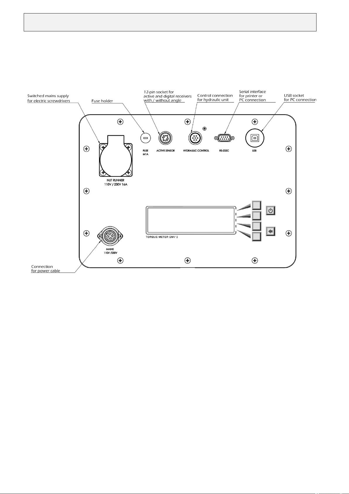
2.3 Connections overview
Subject to change without prior notice

ETH-messtechnik gmbh D-74415 Gschwend P.O. 16
9
Nr.: 162e Operating Instructions GMV2-K revised: 09.05.2019 Rev.: 0
2.4 Connecting the torque transducer
Suitable connection cables are available for different types of torque transducers!
This standard GMV2-K unit has been designed for use with active transducers with a ± 1.25V to ± 10V signal. A
±0.5mV/V to ±4mV/V passive input and a digital input are available as an option. Please use the appropriate cable only
which can be obtained from ETH.
2.5 Switching on
You can switch the unit on with the button when you have checked that the cable has been correctly connected.
After a short self-test all settings valid before the unit was switched off are reloaded. The transducer is now zeroed. The
unit is then ready. If the error message "Charge!" appears now, please connect the power cable. You can now power the
unit from the mains or switch it off and let it charge for approximately five hours.
If you keep the key pressed while switching on the device, time of day, software version and the optional functions will be
displayed. The following abbreviations appear:
• V x.xx Software version
“-”
• ax Active input with adjustable input range
• px Passive input with adjustable input range
• d Digital input
“-”
• W Angle measurement
• T PC transfer
• E I/Os
• D Output for Digimatic printer
Notes:
− When the unit is being switched on the outputs are operated for a short period. The manual switch for the power-
operated screwdriver should therefore be switched off during power-up.
− Check before the first measurement that the initial settings for the unit (see Sec. 6) meet your requirements.
− If the battery is not charged fifteen minutes after the first charge message, the unit switches itself off.
When the calibration period for the GMV2-K has elapsed, the error message
“Error: Calibration date” appears when the device is switched on. In this case, please send the device to ETH.
2.6 Switching off
You can switch off the device with the button. If the power-saving function (standby) is enabled, the device switches
itself off if it unused for a set period. If, due to a fault, you cannot operate or switch off the unit, you can remove the fuse
from the rear (data may however be lost in this case).
Subject to change without prior notice

ETH-messtechnik gmbh D-74415 Gschwend P.O. 16
10
Nr.: 162e Operating Instructions GMV2-K revised: 09.05.2019 Rev.: 0
3 What's new in software version V 5. 1 (after V4.1)
3.1 Dynamic repeat rate for keys
The keys (+, -, choose, etc.) now have a repeat function when pressed for longer periods.
The repeat rate increases continually.
3.2 Automatic conversion of the transducer full scale value to other units
When a transducer with integral chip is connected to the device, a unit that is different to the transducer unit may be
selected in the parameter set. The transducer full scale value is automatically converted to the selected unit. Only the
available units can now be used!
Example:
• Transducer with 10 Nm, selected unit “InLb” displayed full scale value: 88.51 Inlb
• Transducer wit 10 Nm, selected unit “Ncm” displayed full scale value: 1000 Ncm
Note:
• If, when programming a parameter set, a particular unit is not available, disconnect the transducer and then choose the
wanted unit.
3.3 Supporting transducers with two measuring ranges (option on request)
Transducers with two measuring ranges can now be connected to the active socket.
The small measuring range appears in the menu as “akt2rng, standard_range”.
The large measuring range appears in the menu as “akt2rng, high_range”.
Note:
• This is an optional function and is not available in all devices
• Select the “Standard_range” option for transducers with only one measuring range!
3.4 Improved support for a number of inputs
When the GMV2-K supports inputs for a number of transducer models, each of the available inputs can be selected as
required. The GMV2-K socket designation, the transducer model and, if applicable, the measuring range (stndrt / large)
will be displayed.
In addition, this information is also output when the parameter set is displayed or printed out.
Note:
• This is an optional function and is not available in all devices
3.5 Universal input range for the active and passive input
Menu path:
• “Menu -> Param -> ParSet -> Change -> Edit”
• “Menu -> Param -> Transducer -> “Model” or “Sig./Ua”
The inputs can be adjusted easily now to the output signal from most sensors. They can be programmed separately for each
parameter set. If a default value is available, it will be used without the system asking for confirmation. The correct value
can be entered for every parameter set with the setting “Enter” for Ua. This is how the calibration value is entered for
passive transducers.
Input range:
Active input: ±1.25V to ±10V in steps of 1mV, or 5V / 10V
Passive input: ±0.5mV/V to ±4mV/V in steps of 1µV/V, or 1mV/V / 2mV/V / 4mV/V
Note:
This is an optional feature and therefore not available in all devices
Subject to change without prior notice

ETH-messtechnik gmbh D-74415 Gschwend P.O. 16
11
Nr.: 162e Operating Instructions GMV2-K revised: 09.05.2019 Rev.: 0
3.6 Adjustable overload range
Menu path:
• “Menu -> Param -> Param set -> Change -> Edit”
• “Menu -> Measure -> Overload
The measuring range can now be much larger than the nominal signal of the transducer. The overload range can be
programmed separately for each parameter set from 0% to 100% of the transducer end value – however, the resolution of
the displayed measurement is reduced in proportion to the selected overload range. Different values can be programmed by
selecting “Enter” in the defaults under overload range.
(Menu path: “Menu -> Param -> Setting -> Defaults -> Overload”).
Caution
• If the mechanical overload capability of the torque transducer is exceeded for even a short period, this will
immediately destroy the transducer!
3.7 Automatically tracking zero-point drift
The zero voltage on torque sensors varies slightly as a function of temperature: the zero-point drifts when the device is
switched on until the sensor reaches its operating temperature. In the zero-load condition, the system detects and tracks this
drift and compensates for it accordingly. The device continues to take correct measurements. When the tracking function
for zero-point drift is active, an “A” (Automatic) appears at the bottom of the screen.
3.8 Pulse-type screwdriver mode
This function is very similar to the peak measuring function: additionally, a correction factor is available in this mode, but
angle measurements cannot be taken.
3.9 Streamlining parameter set entry
3.9.1 Defaults
Menu path: “Menu -> Param -> Setting -> Defaults”
In “Defaults” either a fixed numerical value or “Enter” may be selected.
The desired value may be entered when programming a parameter set and when “Enter” is set.
When a fixed numerica l value is the default setting, it is automatically loaded without confirmation from the user
when a parameter set is programmed. This saves multiple data entries.
A default setting is available for each of the following:
- input sensitivity of the active and passive input
- overload range
- automatic tracking of zero-point drift
Examples:
• If you always use thread adapter transducers (DRFS..., DRFN...), select active - 5V
• If you always use laboratory transducers (DRL), select active - 10V
• Select passive, Enter for passive transducers
Note:
• Changes to the default setting do not immediately impact the current parameter set!
The default setting is not loaded until a parameter set is processed or programmed.
• Parameter sets that have already been programmed are not changed when defaults are changed.
3.9.2 Hiding unused funct ion s
Menu path: “Menu -> Param -> Setting -> Function”
Functions that are seldom used can be hidden, so that they are disabled (without user confirmation) when a parameter set is
programmed. The process of entering the parameter set is thus shortened.
The functions are always available in the direct parameter entry menu.: “Menu -> Measure ... / Parameter..”.
Subject to change without prior notice

ETH-messtechnik gmbh D-74415 Gschwend P.O. 16
12
Nr.: 162e Operating Instructions GMV2-K revised: 09.05.2019 Rev.: 0
Example:
• The “Parameter set text, data record ID and operator number” menu can be hidden for all operating modes (“More”).
• Angle, speed and power measurement are disabled during tracking measurements.
Note:
• Changing the functions does not immediately impact the currently available parameter sets!
3.9.3 Correction factor
A correction factor may only be entered in the (new) operating mode “impulse wrench”
3.9.4 Filter for peak measuring
This function is no longer available in version V5.2!
3.10 Deleting measured values
Menu path: Menu -> MVclear...
The operator can now choose whether he wants to delete all measured values, the measured values in a parameter set, or
only single data records (see sec. 11.5, page 29).
3.11 Detecting new transducers and new measuring ranges
When ETH transducers that are equipped with a memory chip are used, the GMV2-K detects the removal and insertion of
the transducer, and when the measuring range is changed. The device is subsequently zeroed and the system checks that the
settings in the parameter set match the transducer settings.
3.12 Power-saving function (standby)
Menu path: Menu -> Param -> Setting -> Initial setting -> Standby
To save power, the LCD illumination and the GMV2-K power themselves off after set time periods, which can be adjusted.
This function may also be disabled.
Adjustable delay times for switching off the LCD illumination are: 1 min – 1 h. Adjustable delay times for switching off
the device are: 1 min – 3 h.
Note:
• These delay times are reset when measured values are saved or output.
• The standby function is disabled when the output is continuous.
3.13 Cancel serial transmi ssio n
Serial transmission can be canceled with the OFF key.
3.14 Continuous output with a minimum 0.5 second interval peri od
The minimum cycle time has been increased to 0.5 seconds due to the enhanced functionality of the GMV2-K.
3.15 Analog output
The optional analog output is now zeroed with the Zeroadjust key. Additionally, the automatic tracking of zero-point drift
is enabled.
Note:
• The output signal is scaled to ±5V independently of the input signal (passive, active & digital).
• The overload range must be set to 7% (standard).
Subject to change without prior notice

ETH-messtechnik gmbh D-74415 Gschwend P.O. 16
13
Nr.: 162e Operating Instructions GMV2-K revised: 09.05.2019 Rev.: 0
3.16 Battery protection
To prevent the battery from totally discharging and thus protect it from damage, the device powers itself off when the
battery is low.
4 Menu structure
4.1 Introduction
The GMV2-K offers extensive measuring, control and adjusting features.
A hierarchical menu system is available to allow simple, self-explanatory operation.
A menu offers a list of selection options similar to a menu in a restaurant.
Each selection in turn offers further selections (and so on). A structure is generated that is similar to the branching of a tree.
The menu structure is shown in page 39. The actual functions are situated at the end of the "branches".
When the unit is first switched on it is in normal operating mode, that is, in level 0 in the menu structure. The GMV2-K is
only ready here. In addition to status information, torque, and if necessary angle and OK /NOK assessment (arrows) are
displayed in the first and last lines (see Sec. 2.2, page 7) on the screen.
Use the "Menu" key to enter the menu tree. You may navigate to the right in the tree, that is, to a higher level with the four
menu keys on the right beside the screen.
Use the return key to move back again to the left or to the next lower level.
The menu path is described as "X-> Y-> Z", which means:
When you press menu key ("X"), you reach the next menu. When you press the "Y" key here you reach a menu, where you
can select "Z".
4.2 Direct function keys
In normal operation (level 0) there are three keys with which a function is immediately executed when pressed. Some direct
function keys are assigned multiple functions. The assigned function depends on the settings selected. When no function is
assigned to the key there is no inscription and the key is disabled.
Note: The password for the first level also blocks the direct function keys.
• Store - Output / Start - Stop:
1.) Store: The value displayed on the screen is stored in the measured-value memory every time the key is pressed
(manual save).
2.) Output: The value displayed on the screen is printed out through the RS 232 serial port every time the key is
pressed (one-off manual printout).
3.) Start - Stop: Continuous measured-value output can be started (“contin” appears in the bottom line) or stopped.
• Clear / Zeroadjust:
1.) Clear the measured peak value. Torque and angle of rotation are reset to "0", Counters are reset and restarted. The
unit starts the measuring process from the beginning. The measurement is not stored! Press the Store key beforehand
for manual saving!
2.) Zeroadjust transducer and display. The offset voltage for the transducer is compensated so that, with no loading, the
value "0" appears on the screen. Zeroadjust should be repeated often as every transducer drifts with temperature. The
transducer must be completely unloaded during Zeroadjust!
Notes:
− If the offset voltage is greater than the adjusting range of the unit, an error message is output to the screen, and the
procedure must be repeated. Otherwise, accurate measurements cannot be taken!
This fault may be caused by loading the transducer during Zeroadjust, or it indicates that the transducer (overloading) or
the connection cable are defective.
− The transducer is automatically zeroed when the unit is switched on and when you return from the menu level.
Subject to change without prior notice

ETH-messtechnik gmbh D-74415 Gschwend P.O. 16
14
Nr.: 162e Operating Instructions GMV2-K revised: 09.05.2019 Rev.: 0
• Test:
"Test" serves to test the transducer. It outputs its maximum signal, the full scale value for the transducer is displayed on
the screen. However, this test cannot
“On/Off” button is also available.
The "Return" key serves to return to the previous a level in the menu. Typically, to return to normal operation this key
must be pressed a number of times. If you are in normal operation when you press the "Return" key, you will return to
password level 0.
be performed in the peak measuring mode with counter-clockwise rotation! The
4.3 Measure menu
For direct and fast changeover of the peak, track, torque wrench or speed measurement modes without having to program a
parameter set. Parameter set "0" is selected automatically! Parameter set "0" contains the settings for the current parameter
set.
Notes:
− This menu is only suited for determining screwing parameters. Measured values and parameters cannot be saved!
Finally, you should create a new parameter set with these settings. See sec. 9.7, page 23
− A power-operated screwdriver cannot be switched off during tracking measurements!
− For torque wrench measurements the yielding moment should be at least 2% of the transducer full scale value.
4.4 Menu: Delete measured value
Menu path: Menu-> MVclear ...
See also sec. 11.5, page 29
4.5 Menu: Output
Measured values and parameter sets can be either displayed on the screen (see secs 11.4 and 9.4) or printed out through the
serial interface (see secs 12 and 9.5). Alternatively they can be uploaded to a computer .
In “Menu -> Output-> Display-> Light” the LCD display illumination can be switched on/off and in “Menu -> Output->
Display-> Contrast” the display contrast can be set manually.
4.6 Parameter menu
4.6.1 Transducer
Menu path: Menu-> Param-> Transducer
This menu allows the values for the torque transducer to be set directly in the test phase (parameter set no. 0). It subdivides
into "Full scale value", "Angle" and "Type" or “Sig./Ua” and “Zeroadjust”.
• The full scale value is set with the Entry editor (see Sec. 8.4).
• The "Angle" menu can be used to define whether the transducer used allows an angle measurement.
Angle decoders with 360 pulses per revolution are supported in this version.
The limits must be entered to display the angle on the screen! (Menu-> Parameter-> Limit -> Angle)
Note:
Angle measurement is only available in the software version with suffix "W".
• Different inputs for different transducer types can be selected in the "Type" / “Sig./Ua” menu depending on the
configuration level of the unit. GMV2-K is equipped with an active input as standard. A passive input and a digital
input are available as an option. If the type is selected, the transducer output signal can be entered in volts or mV/V.
• Automatic tracking of zero-point drift can be enabled/disabled in the “zero” menu..
Subject to change without prior notice

ETH-messtechnik gmbh D-74415 Gschwend P.O. 16
15
Nr.: 162e Operating Instructions GMV2-K revised: 09.05.2019 Rev.: 0
4.6.2 Limits
Menu path: Menu-> Param-> Limits
Limits can be set directly in this menu in the test phase (parameter set no. 0). It subdivides into "Torque", "Angle" and
"Timing".
Torque limits:
• All limits are also entered as unsigned numbers for counter-clockwise rotation.
• The limit evaluation display (arrow) uses the angle value (unsigned).
• "Limit max" and "Limit min" define the maximum and minimum allowed torque (OK window).
• "Shut off" determines the torque at which the power-operated screwdriver is switched off. However the "Inputs/outputs"
option and external power circuitry are required for this function and it is only enabled for peak measuring.
"Trigger" defines the torque at which angle counting begins. This is normally the joining torque.
Operation:
The torque limits are not
entered here with the entry editor!
The current value appears on the screen. You can increment or decrement this value with the "+" and "-" keys. A brief
keystroke changes the last digit by a minimum amount. The longer you hold the key pressed, the quicker the display runs.
You should therefore release the key briefly before the desired number to allow you to make the fine adjustment more
slowly.
The "no" key disables the limit value.
Confirm the entry with "OK", because the return key aborts the changes!
Notes:
− All limits are also entered for counter-clockwise rotation as unsigned numbers.
− Torques are entered here without a plausibility check. This means that the minimum value can be set greater than the
peak. The user is responsible for the correctness of the entries here.
− All torques must exceed 5% of the full scale value so as to be detected! If you enter "0" as a trigger, the torque must
exceed 5% of the full scale value for peak measuring, so that angle counting can begin.
Angle limits:
In contrast to the torque limits, angle limits are entered with the Entry editor (see Sec. 8.3). This means that the angle entry
can only be terminated with "OK". The previous menu level is then automatically selected. If the return key is pressed
during entry the previous value is reloaded. There is also no plausibility check here. However if a transducer without angle
is selected, the angle menu is disabled and an error message is output.
You can activate the angle functions with "Menu-> Parameter-> Transducer-> Angle-> on".
• All limits are also entered for counter-clockwise rotation as unsigned numbers.
• The limit evaluation display (arrow) uses the angle value (unsigned).
• "Limit max" and "Limit min" define the allowed maximum and minimum angle of rotation (OK window). Counting
begins when the trigger torque is exceeded. You can define this with the torque limits.
• "Shut off" defines the angle of rotation at which the power-operated screwdriver is switched off. However the
"Inputs/outputs" option and external power circuitry are required for this purpose.
Note:
The "Angle limits" menu is only available in the variant with suffix "W".
Timing:
The times are also entered with the Entry editor (see Sec. 8.3)
Undesirable torque peaks that can occur at the beginning of screwing are suppressed during the "Suppression phase". This
occurs when the power-operated screwdriver is being mounted, and especially with self-tapping screws.
The value "0" disables the timing.
The "After Time" defines how long the peak measuring and angle counting remain active after the power-operated
screwdriver has been switched off. The value “0” disables the time period so that the GMV2-K is always ready. It should
not be too small. Otherwise, the power-operated screwdriver with its centrifugal mass runs on when the measurement has
been stopped. In which case too small a value would be displayed. This time period depends on the screwing application
and must be determined for each individual case. If possible, therefore, you should use the default setting “0” !
If it has to be changed, select a long period!
Subject to change without prior notice

ETH-messtechnik gmbh D-74415 Gschwend P.O. 16
16
Measurement
Level 1
Level 2
Level 3
Password
for
level 1
Password
for
level 3
Password
for
level 2
Passwords set for level 1 to 3
(Level 0)
Measurement
Level 1
Level 2
Level 3
Password set for level 3 only
(Level 0)
Measurement
Level 1
Level 2
Level 3
Password set for level 1 only
(level 0)
Nr.: 162e Operating Instructions GMV2-K revised: 09.05.2019 Rev.: 0
4.6.3 Settings
The GMV2-K settings are described in detail in secs 5 and 6.
4.6.4 Parameter set
This is the most important menu. A parameter set must be created (programmed) before measurements can be taken or
screws can be screwed. This topic is so comprehensive that it is dealt with in a separate section. See sec. 9.
5 Settings
5.1 Functions
Menu path: “Menu -> Param -> Setting -> Function”
You can enable/disable different functions.
5.2 Password
Menu path: “Menu -> Param -> Setting -> Password”
If the password is programmed in the first level, all keys, except the On/Off key and the password prompt are disabled. To
return to level 0, press the “Return” key again in measuring mode!
You can jump from level zero to level 3 by entering the password for level 3 (see diagram).
Note:
• You should assign a password, at least, to the third level to prevent unauthorized persons from setting
• Should you forget your passwords, we can provide you with instructions on how to delete all passwords.
5.3 Initial settings
See sec. 6
5.4 Defaults
See sec.3.9.1, page 11.
You can program a password (maximum 4-digit number) for each of the three levels as a
protection for the device settings against unauthorized change. First, you need to enable
level 3. You can then select the level, for which you want to change the password. The
system prompts you to enter the password. As soon as you enter a number greater than
zero, password protection is enabled and you will be prompted to note down this number.
The password protection in the level is disabled if you enter a zero as password. The
system will then also display the message ”Protection disabled”. The sections in the levels
of the menu structure (sec. 12, page 39) are highlighted in color. The enabled level is
shown on the bottom left of the screen.
Additionally only a certain level may be protected with one
password, which means that different levels of password
protection can be assigned to different user groups.
Example:
If only the password for the third level is programmed (left
diagram), everyone has access to the functions on levels 1 and
2 without a password. Since there is no password available for
the first and second levels, they merge with the measuring
mode. A password is needed for the third level.
passwords!
Subject to change without prior notice

ETH-messtechnik gmbh D-74415 Gschwend P.O. 16
17
Nr.: 162e Operating Instructions GMV2-K revised: 09.05.2019 Rev.: 0
6 Initial settings
6.1 Language
Menu path:
Menu-> Parameter-> Program-> Initial setting-> Language
The unit is fully multilingual. If the language is changed, screen texts, key labels and date format are adapted accordingly.
The setting becomes effective when the language key is pressed (Caution!)
German, English, French and Italian have been realized for this software version.
Note:
Other languages can be realized at customer request.
6.2 Time of day and Date
Menu path:
Menu-> Parameter-> Setting-> Initial Setting -> Clock
The actual time of day is displayed at the bottom of the screen. A flashing underline (cursor) indicates what can be
changed. You can change the compete numbers only with the “+” und “-” keys, i.e. you cannot change the units and tens
separately. The longer you keep the keys pressed, the quicker numbers will change (dynamic).
Use the “<==” key to move between minute, hour, day, month and year. Don't forget to press the OK key to save the time
of day! Press the return key to cancel the setting.
Notes:
− Date and time of day are briefly flashed on the screen w he n the unit is switched on – which allows you to che c k
them.
6.3 Printer (Serial interf a ce)
Menu path:
Menu-> Parameter-> Setting -> Initial setting -> Printer
Procedure:
First select the desired printer. For "Standard" and “==> PC” the system prompts you for the baud rate. No baud rate setting
is required for DP-1 HS.
1.) Selecting the printer:
• "Standard" key for standard printer, (PC transmission with the program “Hyperterminal”)
• “===> PC“ key for measured-value transmission in an EXCEL
The keystroke makes the selection immediately effective and item 2. is selected).
2.) Setting the baud rate:
Default values 1200 baud to 19200 can be selected in succession with "+" and "-" keys.
The OK key accepts the selected setting.
The return key cancels the change and jumps to the "Initial setting" menu.
Notes:
Other formats are available at customer request.
®
file (optional)
• Factory default: baud rate 4800 Bd (suitable for printers supplied by us!), sta ndard printer.
• Transmission format: 8 data bits, no parity, 1 stop bit, XON-XOFF, text transmission
• See Sec. 15. for pin assignment
6.4 USB2.0-Interface
To use the USB2.0 interface, first install the supplied driver software! Only then may the USB port be used.
6.5 Standby (power-saving function)
See sec. 3.12., page 12.
Subject to change without prior notice

ETH-messtechnik gmbh D-74415 Gschwend P.O. 16
18
Nr.: 162e Operating Instructions GMV2-K revised: 09.05.2019 Rev.: 0
6.6 Display illumination
Menu path:
Menu-> Output-> Display-> Light
LCD lighting is turned on and off by pressing the "Light" key.
Note:
• In standby mode, display illumination is switched off after a set period if no keys are pressed (see Sec. 3.13). Press a
key (Test, Return, ...) to switch illumination back on again.
6.7 Contrast of display
Menu path:
Menu-> Output-> Display-> Contrast
Use the“+” and “-” keys to set the contrast. If the contrast is too high, the background will be dark; if the contrast is too
low, the figures will be pale.
Note:
• The contrast should only be changed for extreme ambient temperatures
7 Measuring modes
7.1 Tracking measurements
Appropriate for continuous display of static or very slowly changing torques and angles.
To read the values, the tracking measurements must be slow. The display follows fast changes in torque with a delay,
which depends on the filter setting, see the next section.
Notes:
• Speed measurement and power measurement can be activated here if angle measurement has been de-activated.
• The switch-off function is not available here!
• An adjustable filter can also be programmed (0.1 to 10 s).
• If switched on, the optional angle counting function is permanently enabled. It is reset when the transducer is
zeroadjusted.
7.2 Filter
Menu path: “Menu -> Param -> Param set -> New -> Program”
In the laboratory, very often the torque and the speed do not remain constant during a revolution – this makes it difficult to
read the display. This filter is based on the moving average and it can filter out these fluctuations. The range of the time
period over which the measured values are averaged can be set between 0.1 s and 10 s. This time period applies to the
torque, the speed and thus to the power measurement. Filtering is optimized by selecting the filter time according to the
following formula and by making it as big as possible:
Filter time[s] = n * 60 / speed[min
Example:
For a speed of 30 rev/min, select a time between 2.0 s and 10.0 s.
Note:
Please keep in mind that double the filter time must elapse before the final value appears on the display.
-1
]; n = 1, 2, ....
7.3 Outputting measured values continuously
Menu path: “Menu -> Param -> Param set -> New -> Program”
Tracking measurements can be continuously printed out or saved. The allowed interval time ranges from 0.5 s to 900 s
(15 min). Typically, the maximum output rate is determined by the printer speed.
Subject to change without prior notice

ETH-messtechnik gmbh D-74415 Gschwend P.O. 16
19
Nr.: 162e Operating Instructions GMV2-K revised: 09.05.2019 Rev.: 0
7.4 Speed measurements
This measuring mode is a variation of the tracking measurement and is not a separate operating mode!
It is only a function in its own right in "Menu-> Measure-> Track-> Speed" (parameter set no. 0). During parameter set
programming, speed measurement is activated by selecting tracking measurement without angle measurement and finally
starting speed measurement with "yes". You can select between 60 and 360 pulses per revolution: this allows you to record
the speed for torque transducers with angle measurement.
Notes:
• The speed is determined for the duration of a second.
• Maximum speed: 30, 000
• Accuracy: ±1 digit;
-1
7.5 Power measurement
This mode is an extra function under tracking measurements and is not an operating mode in its own right!
It is only a separate function under “Menu-> Measure-> Track-> Power” (parameter set 0).
Power measurement can be started when programming the parameter set after speed measurement has been enabled.
Selecting the format determines the maximum power that can be displayed. If the scale range is exceeded, “-----” is
displayed.
Note:
• The accuracy of the power measurement function is a function of the accuracy and resolution of the torque and speed
measurements.
• Since the speed per second is measured, additional measurements errors may occur from the time shift during periods
of rapid speed changes. A sufficiently large filter should be used as a remedial measure here.
7.6 Peak measuring
This measuring mode is mainly used in screwing technology. Not only does it allow the largest occurring torque to be
detected, but also offers numerous functions for assembly automation: time-based measuring, screwdriver control,
OK/NOK assessment with setpoint values and automatic storing and erasing of measured values. The status of the
measurement is shown to the left on the bottom of the screen. See Sec. 2.2, page 7.
Explanation of symbols:
* new measurement, before start-up suppression
t start-up suppression is running, no measurement
1 ready for measurement, peak storage
< angle trigger exceeded, angle counting operative
0 shutoff activated
X Measurements stopped (“after time” terminated) / bend detected on torque wrench
! error condition, device not ready for measurements
- device not ready (zeroadjust, etc.)
The adjustable parameters are explained in sec. 9.8 "Parameter set". The time-based sequence is shown in sec. 10.1.
7.7 Torque wrench measurements
This operating mode has been specially designed to check the torque values of torque wrenches. Only clockwise
measurements can be made. The peak torque until the yielding point is reached is displayed. Any further increase in
torque after this point has no effect on the measurement results. Due to the mechanical properties of the wrench, the
yielding torque can only be determined precisely by slowly and smoothly operating the torque wrench. Status “1” –
indicating that the device is ready “–“ is displayed before the measuring process starts. If a bend is detected, “X” is output
as status. The transducer should be selected, so that the minimum wrench torque to be measured is at least 2% of the
transducer full scale value. If a parameter set is programmed, all memory settings such as erasure time can be made.
Note:
• Peak measuring has to be used for torque wrenches not having any torque drop
• The angle measurement is always de-activated here.
Subject to change without prior notice

ETH-messtechnik gmbh D-74415 Gschwend P.O. 16
20
Nr.: 162e Operating Instructions GMV2-K revised: 09.05.2019 Rev.: 0
8 The Entry Editor
8.1 Introduction
The entry editor is used to enter torques, angles, times or to make a selection. Operation is thus standardized.
The editor has three important functions:
• it accepts your entries and allows you to change existing values with the four menu keys
• it allows you to choose between different settings
• it checks your entries.
Value entry and selection are different, the entry of the transducer full scale value is a combination of both. Operating the
editor is fully explained in the following sections.
8.2 Select settings
To program a parameter set you must select from a series of possible settings. You move to the next selection with the
"choose" menu key. The list is always repeated from the beginning. Should you press the key too many times, continue to
press the key until the desired setting appears again between the angle brackets (> <) or is displayed with a flashing
underline (cursor). The entry must be confirmed and terminated with the OK key! The return key reinstates the old
selection and returns to the entry. A short bleep is output as a warning.
8.3 Entering numbers
Torque values, angles, time periods and numbers are entered in a very similar manner. However, the transducer full scale
value is entered somewhat differently.
The heading explains what is being set. The current value is displayed with the predefined unit. The number of decimal
points is fixed and cannot be changed. The entry is made from right to left! That is, first the units, then the tens, then the
hundreds and so forth
The cursor is an important part of the entry. It appears as a flashing bold underline under a number, which indicates that
this position can now be changed.
Every time the "+" key is pressed the complete number is increased by the value of this position (reduced with "-").
If the position number is reduced during this operation, the cursor automatically moves to a lower position!
The "<==" key serves two purposes. It shifts the cursor to the left by one position (from the fifth position back to the first
position). If the first positions are 0, a one is carried. This means that when the initial value is 0 the number 100 can be
entered by pressing "<==" twice.
The entry must be confirmed with "OK" and then terminated.
The return key aborts the changes, restores the old value and moves the cursor to the lowest position..
Tips:
• By pressing the Return key (you can press it twice), the old value is restored and you can restart the entry
• To change the previous position again, you can reset the higher position to 0 with "-". The cursor will then be moved
to a lower non-zero position.
• Should you wish to set the maximum possible value, keep pressing "<==" until a five-digit number, for example
"10000", appears. A plausibility check is started with the OK key. An error message is output and the system
corrects the setting to the maximum possible value. Press OK again to terminate the entry.
• In a similar manner you will obtain the minimum possible value, when you set zero and press OK
• You can enter small numbers conveniently with the “+” and “-” keys, as they respond dynamically
8.4 Transducer full scale value
The data entry editor is active here as well. You may also set the unit and the number of decimal places here.
The transducer full scale value is entered by selecting unit, decimal places and by entering the numerical value. These steps
are described in the previous sections.
The following units can be chosen in this version: Ncm, Nm, kNm, inlb, ftlb, Bar, N and kN.
Subject to change without prior notice

ETH-messtechnik gmbh D-74415 Gschwend P.O. 16
21
Blanks A B C ... Y Z 0 1 2 3 4 5 6 7 8 9
+
Nr.: 162e Operating Instructions GMV2-K revised: 09.05.2019 Rev.: 0
8.5 Alphanumeric texts
The maximum length of the ID text and the description text is 12 characters.
The texts can be input via the keyboard or with a barcode scanner (see below).
Keyboard:
Use the “+” und “-“ keys to select blank, the letters A – Z and numbers 0 – 9:
The “+” and “-“ keys react dynamically, i.e. a brief keystroke changes the number slowly. The number changes quicker
when you hold the keys pressed longer. By hitting the “==> key” you move the cursor ( _ ) – as well as the data entry
position – to the right. After the 12th character the cursor is repositioned at the beginning of the text. You can delete
existing text with the Return key and terminate the text input with the OK key.
Barcode scanner (optional):
You can input these texts more conveniently and quicker with a barcode scanner. You can order a barcode scanner as an
accessory from ETH. Please read the user manual for the scanner before using it. The scanner allows you to use the
characters minus, period and slash (standard). The extended Code 39 allows you to use the entire ASCII character set.
When the text has been scanned, you can still edit it from the keyboard. It has to be acknowledged with the OK key. For
connection to the GMV2-K see page 8.
9 The parameter set
9.1 Introduction
GMV2-K allows complex measurements in screwing technology and offers numerous monitoring and control functions.
The torque can be evaluated in very different ways. All values and settings that influence the procedure and type of
measurement and processing are called parameters.
Typically, the parameters are precisely adapted for the screwing task at hand. It makes sense to assemble all individual
parameters for a screwing sequence in one parameter set. GMV2-K can save 49 such parameter sets. A wide range of
screwing operations can thus be carried out conveniently and in quick succession. When the system is switched on, the last
actual set is selected.
A parameter set must therefore be programmed before measurements can be taken.
9.2 Description text for parameter sets
Menu -> Param -> Param set -> New -> Program (for newly created parameter sets)
Menu -> Param -> Param set -> Change -> Edit (to edit existing parameter sets)
We recommend you write a small text describing the parameter set in order to make it easier to choose a particular set and
to avoid operator errors. This text is displayed at the bottom of the screen. The maximum 12 character long alphanumerical
text is entered at the end of the parameter set programming.
Note: “More settings” must be enabled in the function settings (Menu-> Param-> Setting -> Function)!
9.3 Parameter set "0"
Menu -> Measure
Even when you enter limits directly, you use a parameter set. Please note that set number "0" has different features with
respect to other sets. Since parameter set "0" contains the current settings, it is always overwritten when another set is
selected. It can however be copied to another number. See Sec. 9. 7.
The evaluation of the measurement is based on the values in the parameter set, however changes can be made to set number
"0" at any time. The measured values cannot therefore be stored for parameter set number "0"! It only serves to determine
the individual parameters experimentally.
This set cannot be selected directly: it is therefore disabled. Parameter set "0" is automatically selected when individual
values are changed in a stored parameter set. This can be seen on the parameter set display on the top left of the screen.
Subject to change without prior notice

ETH-messtechnik gmbh D-74415 Gschwend P.O. 16
22
Output Param
-------------------------
Data record length: 6
Input: Socket designation, Input type
DatRec length: Data record length
Nr.: 162e Operating Instructions GMV2-K revised: 09.05.2019 Rev.: 0
9.4 Parameter set display
Menu paths:
1.) Menu-> Parameter-> ParSet-> Display
2.) Menu-> Output-> Display-> Param
The function for displaying individual parameters in a set can be called up in two different ways.
A parameter set is output to the LCD display in a maximum of six pages:
You can page through a parameter set with “Page+” or “Page-”. As soon as the last page is displayed, the first page is
displayed again. Empty pages are automatically skipped. A word in [...] means that this word is only displayed when the
function is enabled.
1. Setting 1:
2. [Setting 2:] [Displays the settings for filter time, speed, power and continuous output]
3. [Setting 3:] [Parameter set text, settings for data record ID and operator number]
4. Torque: All torque values are displayed here
5. [Angle:] [Displays all angle limits values (optional: only available with Version AW)]
6. Times: Displays all times (only available for peak measurements)
The display begins with the first page of the current set. Another parameter set can be displayed now with "Param +" or
"Param -". The page selection is not affected. Parameters from different sets can thus be compared with each other.
Transducer: Transducer full scale value, [measuring range]
Input signal, overload range [,automatic zeroing]
Mode: [Direction,] measuring mode [,correction factor]
Memory setting: Memory setting
9.5 Printout of the Parameter Set
Menu path:
Menu-> Output-> RS232-> Param
All parameter sets are printed out in succession by pressing the "all" key. You may also select an individual set with
"Param +" and "Param -". Hit the OK key to print out this set.
Parameter sets cannot be printed out on the DP-1 HS (optional)!
------------------------ Component 0815-01
PAR: 3
Transd: 200 Nm
Input
Type: 5V Cur2Ran
large_range
Zeroadjust: automatic
Overload: 25 %
Op. mode: Peak
Rot Dir: CW
Torque
- Lim max: 150.0 Nm
- Lim min: 100.0 Nm
- Shutoff: 120.0 Nm
Angle: none
Timing
- Suppr.: - -
- After: undef.
ErasrTm: - Store setting: none
Data record length: undef.
Sample printout of parameter sets:
Wheel rim-III
PAR: 5
Input: 3.320V active
Zeroadjust: automatic
Overload: 50 %
Transducer: 1000 Nm
Mode: Pulse screwdr
Rot Dir: CCW
Co. fact: 86 %
Torque
- Lim max: -800 Nm
- Lim min: -300 Nm
- Shutoff: - -
- Trigger: -200 Nm
Angle: none
Timing
- Suppr.: - -
- After: 1000 ms
- ErasrTm: 1 s
Op. no.: yes
DR ID: yes
Store setting: CanTime
Subject to change without prior notice

ETH-messtechnik gmbh D-74415 Gschwend P.O. 16
23
Nr.: 162e Operating Instructions GMV2-K revised: 09.05.2019 Rev.: 0
9.6 Selection
Menu path:
Menu-> Parameter -> ParSet-> choose
A parameter set becomes the current set when selected and confirmed with "OK". The measurements will be made with
these settings. The number of the selected set is displayed on the top left of the screen to the left. The "return" key aborts
the selection!
Notes:
• The parameters are copied internally to set number "0" with this function. Direct entries are thus overwritten.
• When working with switchable transducers with numerous measuring ranges and measuring-range detection per chip,
the desired parameter set must be programmed and e.g. selected in GMV2-K before the measuring range can be
changed over. Then, the error message is removed and the measuring level is reached by pressing the Return key.
• When you are working with transducers with two measuring ranges the transducer is switched automatically to the
desired measuring range by entering the required measuring channel in the parameter set.
• If the DP-1 HS (optional) is selected as printer and the parameter set contains torque limits, the system prompts you to
transmit the limits to the printer.
9.7 Create new
Menu path:
Menu-> Parameter -> ParSet-> new
To quickly set all necessary parameters for the analyzing unit, a parameter set should be created for this purpose. GMV2-K
can store 49 different sets. The sets are not lost when the unit is switched off.
A new parameter set is automatically assigned the number of the first free memory area. Gaps arising when individual sets
are erased can thus be re-assigned. You may now start programming ("program" menu) or use an existing parameter set as
a template ("Copy" menu). A set, including set number "0", can be selected for copying with "Param - " and "Param +".
After confirmation with "OK" you should start programming. All settings are displayed and the values are checked. A
parameter set is programmed in the same way as with editing. A more detailed description is given in the following section.
Notes:
• When a parameter set is first created, it is automatically selected and becomes the current set.
• If the DP-1 HS (optional) is selected as printer and the parameter set contains torque limits, the system prompts you to
transmit the limits to the printer. The printer has to be connected in this case.
9.8 Editing
Menu path:
Menu-> Parameter -> ParSet-> change-> edit
Settings in existing parameter sets may be altered in this menu. However, if measured values have already been stored with
this set it is protected against changes and an error message will be output. Before a stored parameter set can be used,
measured values stored in this parameter set in the device have to be deleted.
To ensure that all parameters are entered, the user is forced to enter the parameters in succession and to confirm with "OK".
This entry loop cannot be aborted prematurely! However, you can always confirm with "OK" and thus quickly reach the
end of the loop. In which case you must also confirm the last prompt "All entries correct? "" with with "yes". Otherwise the
loop will run through again.
Only the necessary parameters are prompted depending on the selected measuring mode and can be set with the Entry
editor (Sec. 8). The order has been arranged so that a plausibility check of interdependent values is made. If entries are
incorrect, an error message is displayed after confirmation, an acoustic alarm is output and the value is automatically
corrected so that it is within the permissible range!
Some queries can be skipped by having fixed values in the defaults and by hiding functions (see secs 3.10.1 and 3.10.2,
page 11).
Subject to change without prior notice

ETH-messtechnik gmbh D-74415 Gschwend P.O. 16
24
Nr.: 162e Operating Instructions GMV2-K revised: 09.05.2019 Rev.: 0
All available parameters are detailed below:
• Transducer (type):
The input changeover is not available with all software versions!
Changeover between "active", "Cur2Ran", "passive"" and and "digital". Different sockets can be selected as well.
• active-/passive- Sign./Ua:
Adjusting the measurement input to the transducer nominal signal (Ua).
- active: ±1.250V to ±10V or selection of standard values (±5V, ±10V)
- passive: ±0.5mV/V to ±4mV/V or selection of standard values (±1mV/V, ±2mV/V, ±4mV/V)
• Overload:
This is the percentage by which the measuring range of the GMV2-K is greater than the nominal transducer signal.
This allows torques that are greater then the full scale value of the transducer to be measured. It can be used with
pulse-type screwdrivers with the correction factor. The standard value is 7%. The adjustable range is 0% to 100%
Caution
- If the mechanical overload capability of the torque transducer is exceeded for even a short period (see data
sheet), this will immediately destroy the transducer!
- The specified accuracy of transducer is not guaranteed at more than 50% overload
- The GMV2-K resolution worsens accordingly
• Transducer full scale value:
Nominal transducer torque.
Setting range: 1.000 Ncm to 200 kNm; 1.000 inlb to 1999 inlb / ftlb.
• Operating mode:
- Track:
- Peak:
- Torque wrench:
See also sec. 7.7 page 19
- Pulse-type
factor).
Continuous display of current torque, angle of rotation or speed and power.
The highest value is stored. See Sec. 10. for screwings.
For clockwise rotation only. The peak value before yielding point is reached is stored.
screwdriver: Specially designed for pulse-type and impact screwdrivers (peak measuring with correction
• Filter:
Tracking measurements: “Average value for n s”.
0 s: Filter disabled, otherwise average value over a period of n seconds.
Setting range: 0.1 s to 10.0 s.
• Correction factor:
Only available in “Pulse-type screwdriver” mode. It is the ratio of the indicated value to the measured value in
percent. Setting range: 50% to 150%. The default value 100% disables the correction factor.
The measured torque for pulse-type screwdrivers deviates significantly from the torque applied to the screw. The
indicated value can be adapted with the correction factor. It is calculated as follows:
Correction factor = 100% * (measured torque in the screw / uncorrected measured value)
• Direction:
- Peak measuring only: clockwise or counter-clockwise rotation.
• Torque (processing): choose between
- "Display": display only,
- "Monitoring": with limits (OK/NOK assessment), without shut off,
- "Shut off": same as monitoring, with shut off of power-operated screwdriver by external power circuitry, however
only available for peak measurement!
• Torque Limit max: If the measured torque is greater than this limit value, NOK assessment is carried out. Allowed
setting range is 5% to 100% of transducer full scale value including overload range.
Counter-clockwise rotation: unsigned number entry! A correction factor alters the valid setting range!
Subject to change without prior notice

ETH-messtechnik gmbh D-74415 Gschwend P.O. 16
25
Nr.: 162e Operating Instructions GMV2-K revised: 09.05.2019 Rev.: 0
• Torque Limit min: If the measured torque is less than this limit value, NOK assessment is carried out. Allowed
setting range is 5% to 100% of transducer full scale value including overload range, however maximum "Torque Limit
max"! Counter-clockwise rotation: unsigned number entry! A correction factor alters the valid setting range!
• Shut-off torque: If the torque is greater than this limit value, the power-operated screwdriver is shut off by an
external power circuitry. The allowed setting range is 5% to 100% of transducer full scale value including overload
range. Counter-clockwise rotation: unsigned number entry! A correction factor alters the valid setting range
accordingly! Only available with the Inputs/Outputs option!
• Angle (processing): Choose between
The transducer does not have an angle counter or it is out of use.
- "no":
Speed measurement can also be activated subsequently with this setting.
- "Monitoring"
- "Shut off"
however only available for peak measurement! Switching off according to angle of rotation depends on the setting for
torque processing.
Notes:
- The angle measurement is only possible with option "W"!
- With counterclockwise rotation: Entry of numbers without sign (amount)!
- Speed: With "Yes", the speed measurement is activated. This is only available if "no angle" was selected for
cursive measurement. The speed is averaged over one second.
It can be selected whether the transducer is an angle encoder with 360 pulses/rev. or a speed encoder with
60 pulses / rev. Has. Accuracy: ± 1 digit; Maximum speed: 30000 rpm!
: with limits (OK/NOK assessment), without shut off,
: The same as monitoring, with power-operated screwdriver switched off by external power circuitry,
• Speed: Speed measurement is activated with "yes". This is only available when "no angle" is selected for tracking
measurement. The speed is determined for the duration of a second. You can select an angle encoder with 360
pulses/rev or a speed encoder with 60 pulses/rev for the transducer. Accuracy: ±1 digit; max. speed: 30,000 rev/min!
• Power: The power measurement is started with “Yes”. It is only available when speed was selected beforehand.
Subsequently, the maximum
mW to 19999 kW. A filter time on the order of a few seconds must be programmed beforehand for a stable read-out.
power to be measured has to be set with unit and decimal places. Setting range: 1.9999
• Suppression time: To suppress undesirable high torque peaks that can occur at the beginning of the screwing
process. This occurs when the power-operated screwdriver is being mounted, and especially with self-tapping
screws. Timing is started as soon as the torque is greater than 5% of the full scale value. Peak measuring is disabled
until the suppression time has elapsed.
If suppression is not required, the value can be set to "0". The allowed setting range is 0 to 10,000 milliseconds (10
seconds).
Warning:
The suppression time also disables shut off! The protective shut off for transducer overload remains continues to be
enabled however. The angle trigger can also be delayed, so that too small an angle is displayed.
• After Time: The centrifugal mass of the power-operated screwdriver causes it to run on and the torque increases
further even after shut off. The after time defines how long peak measuring and angle counting continues after the
power-operated screwdriver has been switched off. The measurement is then stopped and the values saved.
The value “0” disables this time.
In most cases, we recommend you use the default setting 0. If you select a value for the after time, it should not be
too short to avoid measuring torques that are too small! This value should be determined experimentally, as it also
impacts the angle measurement and is dependent on the screwing operation at hand.
Choose a long time period!
The allowed setting range is 10 to 10,000 milliseconds (10 seconds)
• Memory setting: Choose between "no": measured values are not stored, and "Manual": the measurement must be
saved with the "Store" key. Then reset the peak to zero with the "erase" key. "Erasure time" saves and erases the
peak automatically if OK. This time defines how long a peak stays on the screen.
The allowed setting range is 0,1 to 240 seconds (4 minutes). The setting "RS 232" is similar to the erasure time: the
difference being that the measured value is not stored internally, but is printed out.
For tracking measurements: “contin” is still available for continuous printing.
The permissible setting range is 0.5 s to 900 s (15 min).
Subject to change without prior notice

ETH-messtechnik gmbh D-74415 Gschwend P.O. 16
26
Nr.: 162e Operating Instructions GMV2-K revised: 09.05.2019 Rev.: 0
• Data record length: The number of similar screwings to be stored in one data record. Many measured values can
thus be subdivided sensibly and printing and archiving are easier. Particularly useful for cylinder heads and wheel
rims. The current data record number is displayed on the right of the screen beside the memory number.
If no special subdivision is required, the value can be reset to "0".
A data record length of "1" should be avoided.
The allowed setting ranges from "0" to the remaining memory capacity (maximum 1000 measured values).
• Automatic Zeroadjust (tracking zero-point drift):
Slight transducer zero-point drifts e.g. due to temperature changes are compensated for automatically. As soon as the
transducer is put under load this function is put in abeyance. Only available when the default setting is “Enter”.
• Parameter set text: You can enter a description for the parameter set (alphanumeric with maximum 12 characters).
This text appears at the bottom of the LCD display, see page 7. You can input the text with the input editor,
see page 21. Alternatively, the text can be entered conveniently with a barcode scanner available from ETH. This
facility is only available when “More” is selected during function selection.
• ID text for data records: The ID prompt can be enabled/disabled with the “DescDR” key. The actual text is entered
before the measurement. The operator is prompted again at the beginning of a new data record. In this case, the text
can be input with a barcode scanner.
The current text appears to the right beside the parameter set text (see page 7). This facility is only available when
“More” is selected during function selection.
• Operator number: The operator number prompt can be enabled/disabled with the “OperatorNo” key.
The system prompts you again to enter this number at the beginning of a new data record and is saved in the record.
The current operator number appears to the left of the screen (see page 7). The texts setting and the operator number
must be acknowledged with the “OK” key. This facility is only available when “More” is selected during function
selection.
All necessary parameters have now been entered. Confirm the "All entries correct?" prompt with "yes" to exit the entry
loop; the settings then become immediately effective. You can repeat the entries with "no".
If DP-1 HS (optional) has been selected as printer and the parameter set contains torque limits, you will be prompted to
decide whether the limits should be transmitted to the printer.
9.9 Erase
Menu path:
Menu-> Parameter -> ParSet-> change-> erase
You can select a parameter set with "Param +" and "Param -" before erasing. The number is displayed on the top left of the
screen. As a security measure erase must be confirmed with "yes". This parameter set is now free and will be re-used when
recreated. The error message "ParSet used" indicates that measured values have been stored with it and that it is thus
protected against modification.
Note:
• When the current parameter set is erased the previous set automatically becomes the current set.
To erase several successive parameter sets, start with the highest number. This means that a selection for each
Tip:
one is not required.
• Set number "0" cannot be erased.
Subject to change without prior notice

ETH-messtechnik gmbh D-74415 Gschwend P.O. 16
27
IO-screwing with shut off based on torque and display of angle
Torque /
Angle
Torque limit max
Torque limit min
Peak value of
torque
Shut off
torque
Peak value
of angle
Trigger value
for angle
5% o f
full sca le value
time
tA t
start
t
t
shut o ff
start
end o f measurement
measurement stopped
new
erasure time
Time for s toring
* * time for storing measure ments
withou t confir matio n : < 0,1 second
Nr.: 162e Operating Instructions GMV2-K revised: 09.05.2019 Rev.: 0
10 Screwing Technology
10.1 Time-Based Sequence Diagram
suppression time
s:
N
of torque
measurement
of angle
measurement
After time
a:
measurement
10.2 Timing
• tA: The suppression phase is started once when the torque exceeds 5% of the transducer full scale value. The torque
values are suppressed during this period. This period should not be too long, because when no starting peak occurs,
the time period begins shortly before the screw head is mounted. Angle counting could thus be delayed. Shut off is
also suppressed. The value "0" for t
de-activates the function.
A
• tn: The after time is started once when the shut off has been activated. When this time has elapsed, angle counter and
torque peak measurement are disabled. The after time must be set to suit the screwing sequence dynamics, so that the
power-operated screwdriver run-on is recorded.
We recommend that the default setting “0” is selected. Otherwise select a long time period!
Note:
Without shut off the measurement is not limited by tN and runs on until the peak value is erased.
The maximum value for angle and torque is always displayed and saved for a long after time.
• The era sure time is always restarted with increasing torque. It defines how long the value should remain on the
screen after the final peak. The measurement is then saved, peak values are reset and a new measurement is started.
• The storing time is negligible for an OK screwing. However if measured values are outside the setpoint values
(NOK), storing must be confirmed – thus delaying the procedure.
Subject to change without prior notice

ETH-messtechnik gmbh D-74415 Gschwend P.O. 16
28
Nr.: 162e Operating Instructions GMV2-K revised: 09.05.2019 Rev.: 0
10.3 Angle
Shut off based on angle is also possible with GMV2-K. This is independent of an additional torque shut off and operates in
the same way. Angle counting in the peak operating mode begins when the trigger torque is exceeded. The maximum angle
of rotation is measured. The angle can be reset by clearing the peak value or by zeroadjusting the transducer.
The allowed angle range is ±6,000 degrees. Clockwise or counter-clockwise rotation is possible with peak measuring. Shut
off based on angle is delayed without rise in torque (screw breaking off).
Note:
• Angle measurement is only available in version "W"!
11 Storing measured values
11.1 The measured-value storage
One thousand measured values can be stored in GMV2-K for the documentation and evaluation of screwings. In addition to
torque a measured value contains further information, such as, angle of rotation, OK/NOK assessment, and date and time of
measurement. The values can be saved manually with the save key or automatically by means of an erasure time. The
storing of NOK screwings that are outside the limit values must be confirmed. The memory values are permanently stored
even after the unit has been switched off; they can be displayed at any time, printed out or transmitted to a personal
computer. The measured values are linked to the appropriate parameter set as they depend on the selected settings. Thus the
parameter set is protected against changes as soon as values are stored with it. The numbering of memories (ST:) and the
subdivision into data records (DR:) facilitate the assignment of measured values to the workpiece. Similar screwings are
assembled to a group in one data record, see next section.
The remaining memory, that is the number of free memories, is displayed in the lower status line on the screen with "SR:"
(see sec. 7).
11.2 The data record
Typically, the same screwing operation must be repeated a fixed number of times for each workpiece in assembly lines.
This number can be set as the length of the data record in the parameter set. Screwings are the same when they are
performed in succession with the same parameter set and on the same day.
Especially when many measured values are stored subdividing them in data records facilitates selection for display and
printout, as described in the following sections.
If a data record is fully assigned, a new record is selected automatically. "ST:" defines the screw for the workpiece as the
"ST:" numbering of the memory starts at the beginning with each data record. The data record number thus defines the
workpiece. One ID text and one operator number may also be entered and saved per data record see sec. 9.8.
If the started data record is not fully assigned when the parameter set is changed, the remaining spaces are filled with "No
measurement". The data record number is counted from "1" with every new parameter set
If the number of screwings is unknown, any number can be set with the length of the data record "0" (standard setting!). A
new data record is then started automatically when parameters or the date are changed. A length of "1" is not
recommended.
.
11.3 Memor y Settings
Menu path:
Menu-> Parameter -> ParSet-> change-> edit
The following settings are available:
• "no": Storage disabled. This is mandatory for parameter set "0". However, you can then print out the values shown on
the screen with the key "Output" (level 0).
• "manual": The "Store" key stores the current indicated value in the measured-value memory. For peak measuring the
peak must then be reset with "erase".
• "erasure time": Automatic storing and erasing the peak value when an adjustable time period has elapsed. The
erasure time starts when the torque drops below the maximum value. The allowed range is 0.1 to 240 seconds (2
minutes).
• "RS 232": Similar to erasure time, however the measured value is not stored, but is printed out.
• “Contin”: ”: “continuously” can be selected in tracking measurements. Then, “Memory” is selected for internal storing
or “RS-232”
The permissible range is 0.5 seconds to 900 seconds (15 minutes).
for continuous measurement output. The time defines the time period.
Subject to change without prior notice

ETH-messtechnik gmbh D-74415 Gschwend P.O. 16
29
Menu: Delete measured value
all
yes
no
MVclear
OK
param +
param -
set +
set -
all
yes
no
OK
Nr.: 162e Operating Instructions GMV2-K revised: 09.05.2019 Rev.: 0
Notes:
• If the measured value lies outside the setpoint values (NOK), storing must be confirmed, which in turn interrupts the
erasing procedure.
• If the torque drops temporarily during screwing, the erasure time must be selected sufficiently large.
11.4 Displaying the stored measured values
Menu path:
Menu-> Output-> Display-> Store
In addition to the torque, the angle of rotation or speed and the power may also be displayed. The parameter set, memory
and data record number are also displayed in the top status line. The parameter set text, the ID text for data records, and
below them, the date and time of day of the measurement are shown in the bottom line.
The used parameter set is selected first for output and confirmed with "OK".
Then, use "Record +" and "Record -" to select the next data record, and use "value +" and "value -" to select the next value.
The output is sorted according to data record number. It begins in the first data record with the first measured value. A short
bleep indicates that the end or beginning of memory has been reached.
11.5 Delete measured values
Menu path:
Menu-> MVclear...
You can choose which measured values you want to delete:
• all measured values
• the measured values in a parameter set
• the measured values in a data record
The parameter set will be selected first (or “all”),
then the data record (or “all”).
Notes:
• If you still require some measured values, you can upload data records to a personal computer as described in Sec. 13.4
using a null modem cable and archive them there.
• To edit a parameter set with which values have already been stored, you can enable the parameter set by erasing the
measured values in this parameter set.
Subject to change without prior notice

ETH-messtechnik gmbh D-74415 Gschwend P.O. 16
30
========================
========================
Notes:
Nr.: 162e Operating Instructions GMV2-K revised: 09.05.2019 Rev.: 0
12 Printing out the stored meas ure d val ue s
Menu path:
Menu-> Output-> RS 232-> Store
Measured values are always printed out here in sets and are ordered firstly according to the used parameter set number and
secondly according to the data record number.
You can choose to print out the entire measured-value storage in the first menu "Param + / Param - / all / OK". Use "Param
+" and "Param -" to choose a particular parameter set. Observe the "PAR:" display. "OK" terminates this selection and
branches to the next menu. You can decide now in the menu "Record + / Record - / all / OK" whether you want to print out
all data records in the selected parameter set or only a particular one.
The "all" key starts the printout immediately, it must not be confirmed with "OK"!
Notes:
• An individual measurement can be printed out with the direct function key "Output", when "No storing" is set.
• Some limitations apply to DP-1 HS (optional) (see sec. 13.12):
Examples
• Print out all stored measured values:
Menu -> Output -> RS 232 -> Store -> all.
• Print out all data records that have been measured with the first used parameter set:
Menu -> Output -> RS 232 -> Store -> OK -> all.
DR: 1 PAR: 1 04/21/99
OK No Md/Wkl Time
1 5.95 Nm 09:41
2 6.40 Nm 09:41
3 7.65 Nm 09:41
4 8.73 Nm 09:41
========================
DR: 1 PAR: 2 12/24/02
OK No Print Time
N 1 56.5 Bar 09:33
O 2 101.5 Bar 09:33
O 3 125.3 Bar 09:34
O 4 131.4 Bar 09:34
O 5 133.9 Bar 09:34
N 6 154.8 Bar 09:34
========================
DR: 1 PAR: 6 04/21/99
OK No Md/Wkl Time
1 -9.39 ftlb 09:39
O -145 degrees
2 -9.75 ftlb 09:39
O -179 degrees
========================
PAR: TESTTEXT P5
-----------------------DR: 1 PAR: 5 10/22/02
OK No Md/Wkl Time
1 133 Nm 11:00
833 rev/min
11.601 kW
2 274 Nm 11:00
333 rev/min
9.554 kW
3 900 Nm 11:01
100 rev/min
9.424 kW
Example of a measured-value printout:
PAR: MOT BLOCK WMB
-----------------------DR: 1 PAR: 4 01/06/03
OK No Force Time
I 1 19.58 N 14:36
I 2 19.64 N 14:36
-----------------------Op no: 1001
........................
========================
PAR: WHEELRIM9112
DR: ID3000197028
-----------------------DR: 1 PAR: 6 01/06/03
OK No Md/Wkl Time
O 1 76.75 Nm 14:38
O 2 76.11 Nm 14:41
O 3 75.64 Nm 14:48
N 4 74.25 Nm 14:51
-----------------------Op no: 12
........................
========================
PAR: WHEELRIM9112
DR: ID3000197111
-----------------------DR: 1 PAR: 6 01/06/03
OK No Md/Wkl Time
O 1 77.75 Nm 14:38
O 2 76.43 Nm 14:41
O 3 78.02 Nm 14:48
O 4 75.05 Nm 14:51
-----------------------Op no: 12
........................
• All clearances between
• The end-of-line comprises
• The line length is less than
• Blank lines comprise
• The printout is terminated
• See section 15 for
words are blanks
"CR" and "LF"
32 characters
several "CR"s / "LF"s
with at least one blank line
transmission format and
protocol
Subject to change without prior notice

ETH-messtechnik gmbh D-74415 Gschwend P.O. 16
31
Nr.: 162e Operating Instructions GMV2-K revised: 09.05.2019 Rev.: 0
13 Optional functions
By keeping the power button pressed, the available hardware and software options, the time of day and the date will be
displayed. See sec. 2.5, page 9.
13.1 Battery operation
The device is fitted with an optional battery. The device can run solely on battery power as the torque sensor will also be
powered from the battery.
The lead acid battery requires no maintenance, is protected against overcharging and is automatically recharged during
permanent mains operation. It takes up to a maximum of 12 hours to completely recharge during normal measurement
mode; when the device is switched off it takes up to a maximum of 5 hours to recharge the battery. The device can then run
for at least 6 hours in continuous measurement mode.
The GMV2-K has a battery monitoring feature. If the battery is almost completely discharged, the message “Recharge!”
will be displayed every minute and a beep is sounded as well. The warning message appears permanently at the bottom of
the screen on the right. You should recharge the battery then as soon as possible (you can now run the device with the
mains cable).
Note:
− If the battery charge is very low, the device will switch itself off and it cannot be switched on again.
− The device will function, however, if connected to the mains power system
− If the device is in storage or is unused over a longer period (1/2 year) the battery will have to be recharged.
13.2 Passive input
All passive measuring bridges with a resistance ≥ 350Ω and a signal of 0.5mV/V to 4mV/V can be connected to the device.
The pin assignment for the socket is shown in Sec. 0, page 37 ff.
13.3 Digital input
You can connect the torque sensors fitted with digital output you receive from ETH with this option.
They are connected to the active socket (ACT/DIG).
13.4 Measured-value transmission GMV2-K PC
13.4.1 Function
The supplied EXCEL® files (with program macros) are used for data transmission from GMV2-K to PC, for statistical data
analysis, for archiving and printing out the data. Test logs can also be generated automatically. A sample log for torque
wrenches is supplied with the system. You may add other logs, or adapt existing ones as you wish.
The first page in the file contains the measurement table. The measured values can only be scanned in here. The other
tables and diagrams access them.
Important notes:
! If an error message is displayed when you open the file, you should run the “Setup.Exe” program on the
accompanying CD.
! Before transmission, ensure that “===> PC” is set as printer on the GMV2-K
(Menu-> Param-> Setting-> Program-> Printer-> “===> PC”), select baud rate with “+” and “-”.
! The existing pages should not be deleted or renamed!
! The programming of macros is restricted
13.4.2 Menu bar
An additional menu bar appears on the screen when the file is opened. This menu bar behaves like the other menu bars: it
can be moved and faded in and out. You can select the number of the serial port being used from a list. The displayed baud
rate must be the same as the baud rate selected in GMV2-K. We recommend using a baud rate of 4800.
13.4.3 Data transmission
The “Scan” button activates the RS-232 port and renders the PC ready to receive data. If the table already contains
measured values, the system prompts you to enter whether you want to overwrite these measured values or keep them. In
the latter case, the scanned measured values will be appended to the existing ones. The button then changes to “Finished?”.
Subject to change without prior notice

ETH-messtechnik gmbh D-74415 Gschwend P.O. 16
32
Nr.: 162e Operating Instructions GMV2-K revised: 09.05.2019 Rev.: 0
Tip:
You can overwrite individual measured values before transmission by selecting another cell. The selected cell must be in
the first row of the cell that you want to overwrite. Now you can transfer single measured values, a single data record, or
all data records to the GMV2-K.
In “Menu – Output – RS232 – Store” you can select which data you wish to transmit. You can then see the measured values
being scanned into the table on the PC.
When transmission is complete, you need to acknowledge this by clicking on “Finished?”
If you transmit “all” measured values (all measured values or those from one parameter set), the transmission is
automatically terminated. The button then changes back to “Scan” and the measured-value table is processed:
• empty rows are hidden, used rows are shown
• the measured values are divided according to parameter set und data record numbers by means of dividing bars
• NOK measured values (outside the limits) are stored in red
• Print area und page are automatically set up (!)
13.4.4 Measured-value table
Some of the unused rows may be hidden in the measured-value table. This happens automatically with rows “B” to “L”..
Leave the row “M” empty, as it separates the subsequent rows of comments. You can use the rows of comments as you
will: hide or show them and use them for notes for reading in measured values. They are not altered by the program, and
typically do not a ppe ar in the printout!
The print area is automatically set for all measured values. Should you wish to print out some of the data only, change the
print area beforehand.
Tip:
• If you wish to print comments as well, you can enter any character in the first line in the “M” row and then set the row
width to zero. A comments row is only hidden when it is completely empty.
13.4.5 Statistical analysis
In the “Statistics” page, you can select – according to the parameter set and the data record – which measured values
should be used in the calculation and shown in the diagram.
You can adjust the head of the page, up to the selection fields, as you wish. Do not alter the section containing the statistics!
Although the print area is pre-defined on this page, it can still be altered.
Note:
• When both limit values are negative, counter-clockwise rotation is assumed.
A measured value that is more negative than the limit value, will then be interpreted as being too large! Similarly, a
more positive value is too small!
13.4.6 Measured-value diagram
The data range for the first row of measured values (and for the limits) is automatically set in the dropdown selection
fields. Scaling is also set automatically. You can, however, enter values for (fixed) manual scaling.
You may arrange the diagram (colors, line thickness, ...) as you wish. The best way to do this is to right-click on the desired
element (context menu).
Note:
• By pointing the mouse exactly over a vertex of the curve, the numerical figures will be shown.
• You may insert more self-defined diagram (and table) sheets.
13.4.7 Torque wrench document
This page is intended as a starting point for your own test logs. It accesses the measured-value table via formulas. This is
why you can alter this page as you wish.
Subject to change without prior notice

ETH-messtechnik gmbh D-74415 Gschwend P.O. 16
33
Nr.: 162e Operating Instructions GMV2-K revised: 09.05.2019 Rev.: 0
13.4.8 General information
Two EXCEL® files are supplied:
“GMV2-K-PC-Trans.xls”:
This is the original file, which you should always receive. When you wish to save measured values, first (!) save the
file under a different name (Save under).
“Example-PC-Trans.xls”: This example file contains some measured values, which you can use to test the program and
make changes.
Should you have any queries, please call us on: +49 (0) 7972 / 9310-0
13.5 Inputs / Outputs
This option provides potential-free inputs and outputs for control tasks and displays. This is the prerequisite for the options
in the following chapters 13.6 to 13.11.
13.6 Shutdown for electric screwdri vers
For the supply of an electric screwdriver is a Schuko socket available. 110V / 230V 16A max.
13.7 Shutdown of hydraulic unit
For the control of a hydraulic unit is a 7-pin. Plug available.
Pin assignment of the plug: pin 5 NC; Pin 6 normally open; Pin 7 root; Maximum contact load: 60V AC-DC 1A.
13.8 OK output
Should the torque and, if necessary, the angle be within the programmed limits (total OK), a relay is operated. A floating
make contact is available at pins 13 and 25 on the 25-pin IN/OUT socket (see Sec. 15). It can be loaded with maximum 1
Ampere at 25 V AC / 30 V DC. It is not a heavy-duty relay!
It is however suited for controlling a programmable controller or a contactor.
13.9 NOK output
This output signals an NOK screwing under the following conditions:
1.) At least one limit window (torque / angle) has been programmed.
2.) The measured value must be stored: either with "erasure time", "RS 232" or "manual".
The "RS 232" function can be used when the NOK output is required, however without saving the values. In this case
no printer should be connected.
3.) The torque or possibly the angle lies outside the programmed limits.
4.) The erasure time has elapsed.
The relay contact is closed at the end of the deletion time with a NIO screw connection. At the same time, the query "Save
yes / no" is displayed. After the acknowledgment the contact is opened again. The electrical characteristics are described in
the previous chapter.
13.10 Analog output
The analog torque signal is available with this option at pin 11 on the 25-pin IN/OUT socket so that the torque can also be
evaluated on external equipment such as characteristic curve plotters, storage oscilloscopes and so forth. The reference
potential is GND at pin 5. Ensure that no ground loops are formed as this ground is not electrically isolated from the unit.
The output can be loaded with maximum 5 mA. It is not
The analog output is only scaled to ±5 V when the overload range is set to “7%” (standard). However, it is then
independent of the input and from the input sensitivity!
When the GMV2-K is zeroadjusted, the output signal is zeroed!
Peak storage is not performed.
Subject to change without prior notice
protected against overvoltages.

ETH-messtechnik gmbh D-74415 Gschwend P.O. 16
34
Memory setting
Track
Peak
None
Printout
Printout and erase
Manual
Store
Store and erase
Erasure Time
- - -
Erases NOK values without storing!
RS 232
- - -
not allowed!
Nr.: 162e Operating Instructions GMV2-K revised: 09.05.2019 Rev.: 0
13.11 Ex ternal control
13.11.1 Zeroadjust
Using the floating optocoupler input on the Hydraulic Control connector (see sec.15), the GMV2-K can be snubbed
externally, e.g. be triggered by a PLC.
To control a ON level of 4 V to 30 V DC is required at least 3 mA. The OFF signal must be less than 1.5V.
13.11.2 Storing / Printing / Erasing
The save / print / delete function can be triggered externally via the 7-pole hydraulic control plug (see chapter 15 Pin
assignments). The exact function depends on the operating mode and the memory setting.
Function of external control:
13.12 Measured-value printout to the Digimatic DP-1 HS
13.12.1 Introduction
Torque measured-values can be printed out and statistically evaluated with the "Digimatic Mini-Processor DP-1 HS"
printer. The statistics functions contain:
off-limit condition, number of measurements, max. & min. values, range, mean value, standard deviation, number of
defects, percentage defects, producible index, D board, histogram, random samples.
Parameter sets or angles of rotation cannot be printed out however.
13.12.2 Connection and preparation
The 10-pin, rectangular connector on the cable is inserted in the INPUT socket on the Digimatic printer. The 9-pin SUB-D
connector on the cable is connected with the RS-232 C socket on the GMV2-K.
DP-1 HS must be selected on the GMV2-K under "Menu / Parameter /Setting / Initial setting / Printer". The baud rate need
not be set.
The CL key must be pressed on the printer before the measured values are printed out, when no limits have been previously
transmitted. This is very important when the parameter sets are selected externally. Limits are required for many of the
statistics functions. The transmission is described in the following section.
Subject to change without prior notice

ETH-messtechnik gmbh D-74415 Gschwend P.O. 16
35
Nr.: 162e Operating Instructions GMV2-K revised: 09.05.2019 Rev.: 0
13.12.3 Transmission of limits
If you select or edit a new parameter set in which limits are entered and if you have selected the DP-1 HS as printer (see
previous section), the system will prompt you to transmit the limits to the printer. When not, reselect the selected parameter
set.
If you answer with "yes", then follow the instructions on the GMV2-K screen
The old limits are printed out when you press the CL followed by the TOL.LIMIT key. Wait until the printout is finished,
then quickly confirm with "yes" on the GMV2-K. Now press the data key on the printer. The "NO DATA" error message
may appear. Please ignore this message!
Then acknowledge with" yes”, press the TOL.LIMIT key again and confirm with "yes" on GMV2-K. The transmission is
thus terminated; the new limits will be printed out.
Notes:
• Wait until the printout is finished before hitting the next key on the GMV2-K!
• Once the transmission is started it cannot be aborted!
:
13.12.4 Printing out the measured values
The following printout options are also available with the DP-1 HS setting:
- Single-value printout
- Printout over erasure time (setting: "RS-232")
- Printout one or more data records from a single parameter set (you may need to press the CL key first)
Notes:
• The printer can only process one numeric range. Should the position of the decimal point or the sign change when a
new parameter set is selected, the CL key must be pressed before the first printout.
• If torque and angle of rotation are measured, only the torque can be printed out.
• The parameter sets can still be output to a standard printer or to the PC with the appropriate cable! The baud rate
must be previously selected with the "Standard" setting.
• Most statistics functions require limits. They should be transmitted first.
• Torque values are printed out without units.
• No angle values are printed out!
14 Error messages
14.1 General
The GMV2-K has been designed so that operator errors are almost impossible. Invalid settings are not displayed when
selected and inhibited keys have no inscription.
A plausibility check is performed during parameter set programming so that, for example, the minimum value cannot be set
greater than the peak. The system also ensures that no over-range is possible. An incorrect entry is indicated with an error
message and, if possible, the value is corrected. Invalid operating states are also displayed.
An error message is output at the left-hand side of the LCD display. A beep is also sounded.
There are three different types of messages:
• Notes: For minor faults. This error message is automatically cleared after one second.
• Warnings: One or more functions cannot be started. All GMV2-K functions are stopped until this message is cleared
with the return key.
• Major faults: The GMV2-K is not functioning properly. The unit must be switched off and the fault cleared
Subject to change without prior notice

ETH-messtechnik gmbh D-74415 Gschwend P.O. 16
36
Error Message:
Causes and Error Elimination:
Type:
Transducer
MemChip
Transducer data cannot be scanned
Warning
Transducer
Internal fault when changing to an invalid transducer type
Warning
Transducer ...
...model, values, final value, angle, speed, 60/360 pulses
Transducer data do not match the parameter set
Warning
Transducer
1.) When plugging in the transducer.
ection cable, or with a strong unwanted
signal.
Warning
Output ==>PC
The parameter sets cannot be uploaded to the PC
Warning
CRC MemChip
CRC error when reading the transducer memory chip
Info
Printer
Error during data transmission to printer
Warning
Input
The scanned text is longer than 12 characters
Info
Setting
Error in the settings has been rectified.
Warning
EPROM Memory
Error in internal GMV2-K program memory
Major fault
Calibr. date
The calibration interval has elapsed. Please return the GMV2-K for calibration
Warning
Calibr. memory
Error in calibration memory has been eliminated.
Info
No angle
Setting angle limits is inhibited without the angle measurement option
Info
No calibration
The calibration has been destroyed.
Major fault
Short-circuit
MemChip
The transducer memory chip has a short-circuit
Info
Charge!
The battery is almost fully discharged and must be recharged! The device will
switch itself off after 15 minutes.
Info
MemChip model
Unknown memory chip model
Zeroadjust
1.) The transducer is loaded. Unload and zero again!
2.) The transducer has been overloaded. It is faulty and must be repaired
Warning
Param
An attempt has been made to switch a parameter set externally, while a limit is
being saved. First, delete limit.
Info
ParamSet used
An attempt has been made to alter a parameter set with which values have
ase memory, or copy parameter set to another number.
Info
Param set no.
Parameter set no. 0 cannot be erased.
Info
Param set invalid
A non existent parameter set has been selected externally
Info
Password
Error during password entry: Does this PWD exist?
Info
Password invalid
Incorrect password entered
Info
Angle overflow
The measured angle is greater than ±6000 degrees
Warning
Nr.: 162e Operating Instructions GMV2-K revised: 09.05.2019 Rev.: 0
14.2 Faults and their causes
overload
2.) The transducer has been overloaded or damaged.
3.) With a cable break, with a wrong conn
already been stored. Er
Subject to change without prior notice

ETH-messtechnik gmbh D-74415 Gschwend P.O. 16
37
Signal
Pin
Signal
Pin
Assignment
Pin
Assignment
1
DP-1 HS (Option)
4
DP-1 HS (Option)
2
RXD (Input)
5
GND
3
TXD (Output)
9
DP-1 HS (Option)
Nr.: 162e Operating Instructions GMV2-K revised: 09.05.2019 Rev.: 0
15 Pin Assignments
The description of the pin assignments refers to the unit and are on the rear, as seen from outside.
.
Active and digital transducer socket
(12-pin round socket)
Pin
A Digital Input (Option) G Angle Track A
B Angle Track B H Memory chip
C Torque J Memory chip 2
D Torque GND K Test
E Power supply & angle GND L Torque-2
F Power supply +12V M NC (reserved)
Passive transducer socket with angle (optional)
(14-pin round socket)
Pin Signal Pin Signal
M + Power supply bridge A Memory chip
N Reserved: (+Sense) C 5V angle supply
O Reserved: (-Sense) E Angle und chip ground
P - Power supply bridge G Angle Track A
R +Signal J Angle Track B
S -Signal L unused
T Test U unused
RS-232C / Digimatic mini-processor printer connection
(9-pin SUB-D connector)
Transmission format and protocol (RS-232C):
XON-XOFF, no parity, 8 data bits, 1 stop bit, 4800 baud (preset for printer!)
Notes:
• You can use a serial cable, provided for the PC, as printer cable.
• A null modem cable is required for data transmission to the PC.
• A special cable from ETH must be used for the mini-processor DP-1 HS.
• A sample printout is given in Secs 9.5 and 12.
Subject to change without prior notice

ETH-messtechnik gmbh D-74415 Gschwend P.O. 16
38
Standard
Pin
Assignment
1 NC 2
NC 3
NC 4
NC
Shutdown hydraulic unit
5
opener
Shutdown hydraulic unit
6
turnkey
Shutdown hydraulic unit
7
root
Nr.: 162e Operating Instructions GMV2-K revised: 09.05.2019 Rev.: 0
IN / OUT connector (optional)
(7-pin connector)
Notes:
• Inputs and outputs as well as the socket are optional and not available on all devices.
• level of inputs: inactive: <+ 1,5V; active: + 4V ... + 30V (DC) / ≤ 5mA; "Floating entrances".
• Optocoupler outputs: (galvanically isolated NO contacts) Maximum 150 mA / + 30V (DC)
(Switch-off contact, pin 19 - pin 6, opens when cut-off value has been exceeded)
• Relay outputs: (free normally open contacts) Maximum 1 A / 25V AC / ±30V DC
• Contact load for activation of hydraulic unit max. 60V AC-DC 16A
11 Di s pos a l Considerations
The evaluation unit can be sent back to us free of charge for disposal complete with measuring cable. As soon as the device
is packed with you, send a message to info@eth-messtechnik.de. We then commission our parcel service with pickup.
Unfortunately, we can not accept unannounced par cels sent to us.
Subject to change without prior notice

ETH-messtechnik gmbh D-74415 Gschwend P.O. 16
39
start/
stop/
store/
output
zero/
clear
test
menu/
passwrd
param
measure
output
FullScl
track
peak
display
RS-232
store
param
angle
choose
change
angle
param
store
ParSet
new
display
setting
Bas.set
clock
printer
languag
all
yes
no
transd
copy
program
param +
param -
clear
edit
light
torque
limit
timing
TorqWre
type
MVclear
Password
level 1
Password
level 2
Password
level 3
contrst
CW
CCW
angle
corr.F.
speed
power
angle
passwrd
overlde
+
-
<===
OK
OK
param +
param-
page +
page -
param +
param-
OK
+
-
OK
param +
param-
all
OK
set +
set -
value +
value -
param +
param-
all
OK
choose
Dec.Pnt
<==
OK
off
on
choose
OK
enter
choose
OK
lim max
lim min
SwchOff
lim max
lim min
SwchOff
trigger
suppr
after
+
-
< = =
OK
+
-
< = =
OK
+
-
< = =
OK
funct.
angle
speed
additi.
OK
deutsch
English
francai
italian
+
-
<==
OK
Stndrt
Star 4x
==> PC
default
overlde
passive
active
enter
choose
OK
enter
5V
10V
OK
Param +
Param-
Seite +
Seite -
yes
no
param +
param -
OK
param +
param-
OK
Format
no
yes
no
60 pls
360 pls
no
choose
Dec.Pnt
OK
param +
param -
set +
set -
all
yes
no
OK
BACK
BACK
ON / OFF
ON / OFF
These functions are optional
and are not always available
standby
off
light
GMV2
OK
zero
enter
on
off
OK
zero
yes
no
Nr.: 162e Operating Instructions GMV2-K revised: 09.05.2019 Rev.: 0
12 Overview of the GMV2-K V5.1 Menu Structure
Subject to change without prior notice
 Loading...