

Page 1

User’s Guide
FastFind Links
Unpacking and Installation
Computer Setup
Setting the initial IP address
EtherWAN Managed Switch – V1.94.4
EtherWAN Managed Switch Users Guide
1
Page 2

All Rights Reserved
Dissemination or reproduction of this document, or its contents, is not authorized except
where expressly permitted. Violators are liable for damages. All rights reserved, for the
purposes of patent application or trademark registration.
Disclaimer of Liability
The information contained in this document is subject to change without notice. EtherWAN is
not liable for any errors or omissions contained herein or for resulting damage in connection
with the information provided in this manual.
Registered Trademarks
The following words and phrases are registered Trademarks of EtherWAN Systems Inc.
EtherOS™
Ethernet to the World™
All other Trademarks are property of their respective owners.
Warranty
For details on the EtherWAN warranty replacement policy, please visit our web site at:
https://kb.etherwan.com/index.php?CategoryID=13
Products Supported by this Manual:
V1.94.3 EtherWAN Managed Switch
Contact EtherWAN Systems
Corporate Headquarters
EtherWAN Systems Inc.
2301 E Winston Rd Anaheim
Anaheim, CA 92806
Tel: (714) 779 3800
Fax: (714) 779 3806
Email: support@etherwan.com
EtherWAN Managed Switch Users Guide
ii
Page 3

Preface
Table of Contents
Table of Figures ..................................................................................................... xii
Preface ................................................................................................................... xvi
Changes in this Revision ........................................................................................ xvi
Products Supported ................................................................................................ xvi
Document Conventions ..........................................................................................xvii
Safety and Warnings ..............................................................................................xvii
Typographic Conventions .......................................................................................xvii
Unpacking and Installation ................................................................................... 18
Package Contents ................................................................................................... 18
Unpacking ............................................................................................................... 18
Required Equipment and Software .......................................................................... 19
Computer Setup ..................................................................................................... 20
Management Methods and Protocols ...................................................................... 20
Default IP ................................................................................................................. 21
Login Process and Default Credentials .................................................................... 21
Setting the initial IP address ................................................................................. 22
Simple IP Addressing .............................................................................................. 22
CLI Command Usage ............................................................................................. 23
Navigating the CLI Hierarchy ................................................................................... 23
CLI Keyboard Shortcuts ........................................................................................... 23
CLI Command modes .............................................................................................. 24
Global Configuration Mode ................................................................................ 24
MSTP Configuration Mode ................................................................................. 24
Interface Configuration Mode ............................................................................. 25
VLAN Database Configuration Mode ................................................................. 25
Saving a Configuration from the CLI .................................................................. 25
System Menu ......................................................................................................... 26
System Information .................................................................................................. 26
System Name/Password.......................................................................................... 28
System Name/Password using the CLI .................................................................... 29
Show Switch Model using the CLI ............................................................................ 30
IP Address ............................................................................................................... 30
EtherWAN Managed Switch Users Guide
iii
Page 4

Preface
Static IP ............................................................................................................. 30
DHCP Client ...................................................................................................... 30
Default Gateway ................................................................................................ 30
DNS Server ........................................................................................................ 31
IP Address - Configuration using the CLI ................................................................. 33
IP Address ......................................................................................................... 33
Default Gateway ................................................................................................ 34
Domain Name Server (DNS) .............................................................................. 35
Enable/Disable DHCP Client on a VLAN ............................................................ 36
Enable/Disable Static IP on a VLAN................................................................... 36
Management Interface ............................................................................................. 38
HTTPS ............................................................................................................... 38
Telnet. ................................................................................................................ 38
SSH (Secure Shell) ............................................................................................ 39
Management Interface Configuration using the CLI ................................................. 40
Enabling/Disabling Telnet .................................................................................. 40
Enabling/Disabling SSH ..................................................................................... 41
Enabling/Disabling HTTP and/or HTTPS ........................................................... 42
Save Configuration Page ......................................................................................... 44
Save Configuration ............................................................................................ 44
Load Configuration ............................................................................................. 44
Backup Configuration ......................................................................................... 44
Restore Default .................................................................................................. 45
Auto Save .......................................................................................................... 45
Save Configuration Page using the CLI ................................................................... 46
Saving a Configuration ....................................................................................... 46
Restore Default Settings .................................................................................... 46
Load Configuration from a TFTP Server ............................................................ 47
Save Configuration to a TFTP Server ................................................................ 47
Auto Save Configuration .................................................................................... 48
Firmware Upgrade ................................................................................................... 49
Firmware Update using the CLI ............................................................................... 50
Reboot ..................................................................................................................... 51
Reboot using the CLI ............................................................................................... 51
Logout ..................................................................................................................... 51
Logout from the CLI ................................................................................................. 51
User Account Page .................................................................................................. 52
Changing the User Mode ................................................................................... 52
Creating a New User .......................................................................................... 53
Changing an Existing User Account ................................................................... 54
User Privilege Configuration .................................................................................... 55
User Account Settings using the CLI........................................................................ 57
Multi-User Mode................................................................................................. 57
EtherWAN Managed Switch Users Guide
iv
Page 5

Preface
Single User Mode .............................................................................................. 57
Radius User Mode ............................................................................................. 58
Creating a New User .......................................................................................... 59
Permissions ....................................................................................................... 59
Diagnostics ............................................................................................................ 60
Utilization ................................................................................................................. 60
System Log.............................................................................................................. 61
System log using CLI command .............................................................................. 61
Remote Logging ...................................................................................................... 62
Remote Logging using CLI commands .................................................................... 64
ARP Table ............................................................................................................... 65
ARP Table using CLI Commands ............................................................................ 66
Route Table ............................................................................................................. 67
Route Table Using CLI Commands ......................................................................... 67
Alarm Setting ........................................................................................................... 68
Port ......................................................................................................................... 69
Configuration ................................ ................................................................ ........... 69
Port Status ............................................................................................................... 71
Rate Control ............................................................................................................ 71
RMON Statistics ...................................................................................................... 73
Per Port VLAN Activities .......................................................................................... 74
Port Security ............................................................................................................ 75
Setting the Port Description ............................................................................... 76
Enable or Disable a Port .................................................................................... 76
Setting the Port Speed ....................................................................................... 77
Setting Port Duplex ............................................................................................ 77
Enable or Disable Port FlowControl ................................................................... 78
Display Port Status ............................................................................................ 78
Setting a Ports Rate Control .............................................................................. 78
Display a Ports RMON Statistics ........................................................................ 79
Display a Ports VLAN Activities .......................................................................... 79
Setting MAC Port Security ................................................................................. 79
Switching ................................................................................................................ 81
Bridging ................................................................................................................... 81
Aging Time......................................................................................................... 82
Threshold Level ................................................................................................. 82
Storm Control Type ............................................................................................ 82
Port Isolation ...................................................................................................... 83
Block Multicast ................................................................................................... 83
Loopback Detect ...................................................................................................... 85
EtherWAN Managed Switch Users Guide
v
Page 6

Preface
Loopback Detection (Global) .............................................................................. 85
Loopback Detect Action ..................................................................................... 85
Loopback Detect Recovery Time ....................................................................... 85
Polling Interval ................................................................................................... 86
Loopback Detection (Per Port) ........................................................................... 87
Storm Detect ............................................................................................................ 88
Enable/Disable Storm Detection ........................................................................ 88
Static MAC Entry ..................................................................................................... 90
Adding a Static MAC Address to a Port .............................................................. 90
Removing a Static MAC Address from a Port ..................................................... 91
Adding a MAC to the Static-MAC-Entry Discard Table ....................................... 91
Removing a MAC address from the Static-MAC-Entry Discard Table ................ 92
Port Mirroring ........................................................................................................... 93
Link State Tracking .................................................................................................. 95
Enable/Disable Link State Tracking ................................................................... 95
Port Settings ...................................................................................................... 95
PoE (Power over Ethernet) - System and Port Settings ........................................... 97
PoE System Setting ........................................................................................... 97
PoE Port Setting ................................................................................................ 98
PoE Scheduling ..................................................................................................... 100
Switch Configuration Examples Using CLI Commands .......................................... 102
Setting the Aging Time Value ........................................................................... 102
Enabling Port Isolation ..................................................................................... 102
Enabling Block Multicast .................................................................................. 103
Setting Storm Control ....................................................................................... 103
Enabling Loopback Detect (Global) .................................................................. 104
Setting the Loopback Detect Action ................................................................. 104
Setting the Loopback Detect Recovery Time ................................................... 104
Setting the Loopback Detect Polling Interval .................................................... 105
Enabling Loopback Detect (Port) ..................................................................... 105
Configuring Storm-Detect ................................................................................. 106
Adding a MAC Address for Static-MAC-Entry Forwarding ................................ 110
Adding a MAC Address for Static-MAC-Entry Discarding ................................. 110
Configuring Port Mirroring ................................................................................ 111
Enabling a Link State Tracking Group .............................................................. 111
Assigning a Port to a Link State Tracking Group .............................................. 112
Setting PoE Power Budget ............................................................................... 112
PoE Port Settings............................................................................................. 113
PoE Scheduling ............................................................................................... 116
Trunking ............................................................................................................... 119
Overview ............................................................................................................... 119
Static Channel Trunking ................................................................................... 119
EtherWAN Managed Switch Users Guide
vi
Page 7

Preface
Link Aggregation Control Protocol .................................................................... 119
Port Trunking ......................................................................................................... 120
LACP Trunking ...................................................................................................... 123
Trunking Configuration Examples Using CLI Commands ....................................... 127
Adding an Interface to a Static Trunk ............................................................... 127
Adding an Interface to a LACP Trunk ............................................................... 127
Setting the LACP Port Priority .......................................................................... 128
Setting the LACP Timeout ................................................................................ 128
STP/Ring Page – Overview ................................................................................. 129
Choosing the Spanning Tree Protocols .................................................................. 129
Spanning Tree Protocol (STP) ......................................................................... 129
Rapid Spanning Tree protocol (RSTP) ............................................................. 129
Multiple Spanning Tree Protocol (MSTP) ......................................................... 129
STP/Ring Page - Configuring RSTP ................................................................... 130
Global Configuration Page ..................................................................................... 130
Enabling the RSTP Protocol ............................................................................ 130
Additional Global Configuration page settings .................................................. 130
The Root Bridge & Backup Root Bridge ........................................................... 132
Setting the MAX Age, Forward Delay and Hello Timer ..................................... 134
RSTP Port Setting Page ........................................................................................ 136
Spanning Tree Port Roles ................................................................................ 136
Path Cost & Port Priority .................................................................................. 137
Point to Point Link ............................................................................................ 139
Edge Port ......................................................................................................... 139
RSTP Configuration Examples Using CLI Commands ........................................... 140
Enabling the Spanning Tree Protocol ............................................................... 140
Bridge Priority, Max Age, Forward Delay, and Hello Time ................................ 140
Modifying the Port Priority and Path Cost ......................................................... 141
Manually Setting a Port to be a Shared or Point to Point Link .......................... 141
Enabling/Disabling a port to be an Edge Port ................................................... 142
STP/Ring Page - Configuring MSTP ................................................................ ... 143
Global Configuration Page ..................................................................................... 143
Enabling the MSTP Protocol ............................................................................ 143
The CIST Root Bridge & Backup CIST Root Bridge ......................................... 145
Setting Bridge Priority ...................................................................................... 145
Configuring the CST Network Diameter ........................................................... 147
MSTP Properties Page .......................................................................................... 148
Configuring an MSTP Region........................................................................... 148
Configuring the IST Network Diameter ............................................................. 150
MSTP Instance Setting Page ................................................................................. 151
vii
EtherWAN Managed Switch Users Guide
Page 8

Preface
Setting an MSTP Instance ............................................................................... 151
Modifying MSTP parameters for load balancing ............................................... 152
MSTP Port Setting page ........................................................................................ 154
Adjusting the blocking port in a MSTP network ................................................ 154
MSTI Instance Port Membership ...................................................................... 156
MSTP Configuration Examples Using CLI Commands .......................................... 157
Enabling Spanning Tree for MSTP ................................................................... 157
Bridge Priority, Max Age, Forward Delay, and Hello Time ................................ 158
IST MAX Hops ................................................................................................. 158
MSTP Regional Configuration Name and the Revision Level ........................... 159
Creating an MSTI Instance .............................................................................. 159
Setting MSTI Priority ........................................................................................ 160
Modifying CIST Port Priority and Port Path Cost .............................................. 160
Adding a Port to an MSTI Instance .................................................................. 161
STP/Ring Page - Alpha Ring ............................................................................... 162
Alpha Ring Setting Page ........................................................................................ 162
EtherWAN α-Ring Technology ......................................................................... 162
Implementing a Simple α-Ring ......................................................................... 162
Connecting two α-Ring Networks together ....................................................... 164
STP/Ring Page – Alpha Chain ............................................................................ 165
The Alpha Chain Protocol ...................................................................................... 165
General Overview .................................................................................................. 165
Alpha Chain Settings ............................................................................................. 166
Global Settings ................................................................................................ 166
Configuring the Alpha Chain Ports ................................................................... 167
Alpha Chain Pass-Through Ports ........................................................................... 169
Configuring Alpha Chain using CLI commands ...................................................... 170
Storm Control ................................................................................................... 170
Configuring Chain Ports ................................................................................... 170
Configuring Chain Pass-Through Ports ............................................................ 171
STP/Ring Page - Advanced Setting .................................................................... 172
Advanced Bridge Configuration ............................................................................. 172
Advanced Per Port Configuration ........................................................................... 173
Configuring Spanning Tree Advanced Settings using CLI commands.................... 174
Enabling BPDU Guard Globally ....................................................................... 174
Enabling BPDU Guard on a Port ...................................................................... 174
Enabling BPDU Guard Error Disable-timeout ................................................... 175
VLAN ..................................................................................................................... 176
Port Based VLAN vs. Tagged Based VLAN ........................................................... 176
viii
EtherWAN Managed Switch Users Guide
Page 9

Preface
Configuring VLANs in Port Based VLAN Mode ...................................................... 176
Enabling Port Based VLAN .............................................................................. 176
Port Based VLAN Configuration Examples ...................................................... 177
Port Based VLAN Configuration Examples using CLI Commands ................... 179
VLAN Configuration in 802.1Q Tag Based VLAN Mode ......................................... 180
General Overview ............................................................................................ 180
Enabling 802.1Q Tagged Based VLAN ............................................................ 181
Configuring 802.1Q VLAN Database................................................................ 182
802.1Q Tag Based VLAN Configuration Examples Using CLI Commands ............ 183
Configuring a 802.1Q VLAN ............................................................................. 183
Configuring an IP Address for a Management VLAN ....................................... 183
Removing an IP Address from a Management VLAN ....................................... 184
Configuring an Access Port .............................................................................. 184
Configuring a Trunk Port .................................................................................. 185
Add an IP to the Management VLAN ..................................................................... 186
Configuring the Port Type and the PVID setting ..................................................... 187
Configuring the VLAN Egress (outgoing) Member Ports .................................. 188
QoS ....................................................................................................................... 190
Global Configuration Page ..................................................................................... 191
Web GUI Interface ........................................................................................... 191
QoS Global Configuration using the CLI Interface ................................................. 193
Enable/Disable QoS Trust ................................................................................ 194
Configuring the Egress Expedite Queue .......................................................... 194
802.1p Priority Page .............................................................................................. 196
Web GUI Interface ........................................................................................... 196
802.1p Priority Submenu – CLI Interface ............................................................... 197
DSCP Page – HTTP Interface ............................................................................... 198
DSCP Submenu – CLI Interface ............................................................................ 199
QoS Interface Commands – CLI Interface ............................................................. 200
ACL (Access Control List) .................................................................................. 201
General Overview .................................................................................................. 201
Configuring ACL .................................................................................................... 202
ACL Policy Map ..................................................................................................... 204
IP Access List .................................................................................................. 205
IP Access List (Extended) ................................................................................ 206
Mac Access List ............................................................................................... 208
Layer 4 ............................................................................................................. 210
Bandwidth Limiting ........................................................................................... 211
Applying a Policy Map to a Port ....................................................................... 213
Modifying/Adding an Existing Policy Map ......................................................... 214
Adding a New ACL Class to an Existing Policy Map ........................................ 214
EtherWAN Managed Switch Users Guide
ix
Page 10

Preface
Adding an Existing ACL Class to an Existing Policy Map ................................ . 215
Removing an ACL Class .................................................................................. 217
ACL Configuration Examples Using CLI Commands ............................................. 221
Enabling QoS ................................................................................................... 221
Creating a Standard IP Access List .................................................................. 222
Creating an Extended IP Access List ............................................................... 222
Creating a MAC Access List ............................................................................ 223
Creating an ACL Class Map with Layer 4 Access List ...................................... 224
Creating a ACL Class Map with an IP or MAC Access List .............................. 225
Creating an ACL Policy Map ............................................................................ 226
Appling an Existing ACL Policy to a Port .......................................................... 227
Deleting an ACL Class ..................................................................................... 227
Deleting an ACL Policy .................................................................................... 228
SNMP .................................................................................................................... 229
SNMP General Settings ......................................................................................... 229
Configuring SNMP v1 & v2 Community Groups ..................................................... 232
Configuring SNMP v3 Users .................................................................................. 234
Adding SNMP v3 Users to the switch ............................................................... 234
Deleting SNMP v3 Users from the switch ......................................................... 237
SNMP Configuration Examples Using CLI Commands .......................................... 238
Enabling SNMP and configuring general settings............................................. 238
Configuring SNMP Traps ................................................................................. 239
Configuring SNMP v1 & v2 Community Groups ............................................... 241
Adding SNMP v3 Users ................................................................................... 241
IEEE 802.1X .......................................................................................................... 242
Configuring 802.1X from the GUI system ............................................................... 242
Enabling Radius ............................................................................................... 242
Adding a Radius Server ................................................................................... 243
Enabling 802.1X on a Port ............................................................................... 245
LLDP ..................................................................................................................... 247
LLDP General Settings .......................................................................................... 248
Enable/Disable LLDP ................................ ....................................................... 248
Holdtime Multiplier ........................................................................................... 248
Global TLV Setting ........................................................................................... 249
LLDP Ports Settings .............................................................................................. 251
Enabling LLDP transmission for a specific Port ................................................ 251
Enabling LLDP Reception for a specific Port .................................................... 251
Enabling Notifications ...................................................................................... 251
LLDP Neighbors .................................................................................................... 253
LLDP Statistics ...................................................................................................... 254
EtherWAN Managed Switch Users Guide
x
Page 11

Preface
LLDP Configuration Examples Using CLI Commands ........................................... 255
Enable/Disable LLDP ................................ ....................................................... 255
LLDP Holdtime Multiplier .................................................................................. 256
LLDP Transmit Interval .................................................................................... 256
Enable/Disable Global LLDP TLVs .................................................................. 257
Enabling LLDP Transmit on a Port ................................................................... 258
Enabling LLDP Receive on a Port .................................................................... 258
Enabling LLDP Notify ................................ ....................................................... 259
Enabling Transmission of the Management IP ................................................. 259
Enabling Specific TLV’s on a Port .................................................................... 260
Other Protocols.................................................................................................... 261
GVRP .................................................................................................................... 261
General Overview ............................................................................................ 262
Enabling the GVRP Protocol at the Global Level ............................................. 263
Enabling the GVRP Protocol at the Port Level ................................................. 264
GVRP Configuration Examples Using CLI Commands .................................... 265
IGMP Snooping ..................................................................................................... 268
General Overview ............................................................................................ 268
Enabling the IGMP Snooping Modes ............................................................... 269
Configuring IGMP Snooping General properties .............................................. 270
Configuring IGMP Passive Mode Specific properties ....................................... 271
Configuring IGMP Querier Mode Specific properties ........................................ 272
Configuring IGMP Unknown Multicast Forwarding ........................................... 273
Monitoring Registered Multicast Groups .......................................................... 277
IGMP Configuration Examples Using CLI Commands ..................................... 278
Network Time Protocol .......................................................................................... 286
Enabling NTP ................................................................................................... 286
Setting the NTP Server IP Address .................................................................. 286
Setting the Timezone ....................................................................................... 286
Setting the Polling Period ................................................................................. 286
Manually Syncing Time .................................................................................... 287
Daylight Savings Time - Weekday Mode .......................................................... 287
Daylight Savings Time – Date Mode ................................................................ 288
Network Time Protocol Configuration Examples Using CLI Commands ........... 290
GMRP .................................................................................................................... 293
General Overview ............................................................................................ 293
GMRP Normal mode ........................................................................................ 293
GMRP Fixed mode .......................................................................................... 293
GMRP Forbidden mode ................................................................................... 294
GMRP Forward All mode ................................................................................. 294
GMRP Disabled mode ..................................................................................... 294
Enabling the GMRP Feature Globally on the Switch ........................................ 294
EtherWAN Managed Switch Users Guide
xi
Page 12

Preface
Configuring the GMRP Feature Per Port .......................................................... 295
GMRP Configuration Examples Using CLI Commands .................................... 298
DHCP Server ......................................................................................................... 300
General Overview ............................................................................................ 300
Configuring the DHCP Server .......................................................................... 300
DHCP Configuration Examples Using CLI Commands .................................... 303
DHCP Relay ................................................................ .......................................... 304
General Overview ............................................................................................ 304
Configuring the DHCP Relay ........................................................................... 304
DHCP Relay Configuration Examples Using CLI Commands........................... 306
TABLE OF FIGURES
Figure 1: Login screen ......................................................................................................... 21
Figure 2: Assigning an IP address ....................................................................................... 22
Figure 3: System Information .............................................................................................. 27
Figure 4: System Name/Password ...................................................................................... 28
Figure 5: IP Address............................................................................................................ 32
Figure 6: Management Interface.......................................................................................... 39
Figure 7: Save Configuration Page ...................................................................................... 45
Figure 8: Firmware Upgrade Page ...................................................................................... 50
Figure 9: User Mode............................................................................................................ 52
Figure 10: Creating Users ................................................................................................... 53
Figure 11: Selecting an Existing User Account .................................................................... 54
Figure 12: Deleting a User Account ..................................................................................... 54
Figure 13: User Privilege Page ............................................................................................ 56
Figure 14: Utilization Page .................................................................................................. 60
Figure 15: System Log ................................................................................................ ........ 61
Figure 16: Remote Logging Page ........................................................................................ 63
Figure 17: ARP Table .......................................................................................................... 65
Figure 18: Route Table ........................................................................................................ 67
Figure 19: Alarm Trigger ..................................................................................................... 68
Figure 20: Trigger Enable .................................................................................................... 68
Figure 21: Port Configuration .............................................................................................. 70
Figure 22: Port Status ......................................................................................................... 71
Figure 23: Rate Control ....................................................................................................... 72
Figure 24: RMON Page ....................................................................................................... 73
Figure 25: Port VLAN Activities ........................................................................................... 74
Figure 26: Port Security ....................................................................................................... 75
EtherWAN Managed Switch Users Guide
xii
Page 13

Preface
Figure 27: Bridging .............................................................................................................. 84
Figure 28: Loopback Detection ............................................................................................ 86
Figure 29:Loopback Detection (port) ................................................................................... 87
Figure 30: Storm Detect – Global ........................................................................................ 88
Figure 31: Storm Detect – Per Port ..................................................................................... 89
Figure 32: MAC Static Entry ................................................................................................ 90
Figure 33: Removing a Static MAC ..................................................................................... 91
Figure 34: Adding a MAC – Static-MAC-Entry Table ........................................................... 91
Figure 35: Deleting a MAC – Static-MAC-Entry Table ......................................................... 92
Figure 36: Port Mirroring ..................................................................................................... 94
Figure 37: Disabling Port Mirroring ...................................................................................... 94
Figure 38: Link State Tracking ............................................................................................. 95
Figure 39: Link State Tracking – Port Settings..................................................................... 96
Figure 40: PoE System Setting ........................................................................................... 97
Figure 41: PoE Port Setting ................................................................................................. 99
Figure 42: Selecting a Port ................................................................................................ 100
Figure 43: PoE Power Scheduling ..................................................................................... 101
Figure 44: Port Trunking – Version 1 ................................................................................. 121
Figure 45: Port Trunking – Version 2 ................................................................................. 122
Figure 46: LACP Trunking Version 1 ................................................................................. 124
Figure 47: LACP Trunking – Version 2 .............................................................................. 126
Figure 48: STP/Ring Global Configuration ......................................................................... 131
Figure 49: Bridge ID .......................................................................................................... 132
Figure 50: Bridge ID Display .............................................................................................. 133
Figure 51: Max Age, Hello Timer & Forward Delay ............................................................ 135
Figure 52: Spanning Tree Port Roles ................................................................................ 136
Figure 53: Port ID ................................ ................................................................ .............. 137
Figure 54: Port Priority and Path Cost ............................................................................... 138
Figure 55: Enabling MSTP ................................................................................................ 144
Figure 56: Bridge ID .......................................................................................................... 145
Figure 57: Bridge ID Display .............................................................................................. 146
Figure 58: Max Age, Hello Timer & Forward Delay ............................................................ 148
Figure 59: MSTP Region and Revision Level ................................ .................................... 149
Figure 60: MSTP Properties – Max Hops .......................................................................... 150
Figure 61: VLAN Instance Configuration ........................................................................... 152
Figure 62: VLAN Instance ID ............................................................................................. 152
Figure 63: Setting the MSTI Regional Root Bridge ............................................................ 153
Figure 64: Port Cost & Priority ........................................................................................... 155
Figure 65: Port Instance Configuration .............................................................................. 156
Figure 66: Port Instance - Adding Ports ............................................................................. 157
Figure 67: α-Ring Settings ................................................................................................. 163
Figure 68: Ring Coupling ................................................................................................... 164
Figure 69: Alpha Chain Setting .......................................................................................... 167
EtherWAN Managed Switch Users Guide
xiii
Page 14

Preface
Figure 70: Chain Ports – Master and Slave on one Switch ................................................ 167
Figure 71: Chain Ports – Master Chain Port ...................................................................... 168
Figure 72: Advanced Bridge Configuration ........................................................................ 172
Figure 73: Advanced Per Port Configuration ..................................................................... 173
Figure 74: Port Based VLAN ............................................................................................. 176
Figure 75: Port Based VLAN – Example 1 ......................................................................... 177
Figure 76: Port Based VLAN – Example 2 ......................................................................... 178
Figure 77: Tag-based VLAN .............................................................................................. 181
Figure 78: Add VLAN ........................................................................................................ 182
Figure 79: Add VLAN Page ............................................................................................... 182
Figure 80: Management VLAN IP Address ........................................................................ 186
Figure 81: VLAN Port Setting ............................................................................................ 187
Figure 82: VLAN Links ...................................................................................................... 188
Figure 83: VLAN Ports ...................................................................................................... 189
Figure 84: Tag or Untag ports ........................................................................................... 189
Figure 85: Global Configuration ......................................................................................... 191
Figure 86: 802.1p Priority .................................................................................................. 196
Figure 87: DSCP ............................................................................................................... 198
Figure 88: Enabling QoS ................................................................................................... 203
Figure 89: Policy Map ........................................................................................................ 204
Figure 90: IP Access List ................................................................................................... 205
Figure 91: Access List Extended ....................................................................................... 206
Figure 92: MAC Access list ............................................................................................... 208
Figure 93: Layer 4 ............................................................................................................. 210
Figure 94: IP Access List Name ........................................................................................ 211
Figure 95: Police Rate ....................................................................................................... 212
Figure 96: Policy Map Name ............................................................................................. 212
Figure 97: Applying a Policy Map to a Port ........................................................................ 213
Figure 98: Modifying a Policy Map ..................................................................................... 214
Figure 99: Adding a New ACL Class to an Existing Policy Map ......................................... 215
Figure 100: Policy Map Setting – Class Name................................................................... 216
Figure 101: Policy Map Setting .......................................................................................... 216
Figure 102: Removing an ACL Class ................................................................................ 217
Figure 103: Verifying ACL Class Removal ......................................................................... 218
Figure 104: Removing a Policy Map .................................................................................. 219
Figure 105: Policy Map 2 ................................................................................................... 220
Figure 106: Policy Map 3 ................................................................................................... 221
Figure 107: SNMP General Settings ................................................................................. 231
Figure 108: Community Name V1/V2c .............................................................................. 232
Figure 109: Add User ........................................................................................................ 234
Figure 110: SNMP v3 Settings ................................................................ .......................... 235
Figure 111: User name & Access Mode ............................................................................ 235
Figure 112: Auth Password ............................................................................................... 236
EtherWAN Managed Switch Users Guide
xiv
Page 15

Preface
Figure 113: Privacy PassPhrase ....................................................................................... 236
Figure 114: Delete User .................................................................................................... 237
Figure 115: Select User ..................................................................................................... 237
Figure 116: Enable Radius ................................................................................................ 243
Figure 117: Radius Setup .................................................................................................. 244
Figure 118: Resulting Radius Server Setup ....................................................................... 245
Figure 119: Enabling 802.1X on a Port .............................................................................. 246
Figure 120: LLDP Global Settings ..................................................................................... 250
Figure 121: LLDP Ports Settings ....................................................................................... 252
Figure 122: LLDP Neighbors ............................................................................................. 253
Figure 123: LLDP Statistics ............................................................................................... 254
Figure 124: GVRP ............................................................................................................. 261
Figure 125: GVRP Configuration Distribution Switch ......................................................... 263
Figure 126: GVRP Configuration Access Switch ............................................................... 263
Figure 127: GVRP Per Port Settings ................................................................................. 264
Figure 128: IGMP Mode .................................................................................................... 269
Figure 129: IGMP General Properties ............................................................................... 270
Figure 130: IGMP Passive Mode ....................................................................................... 271
Figure 131: Querier Mode Properties ................................................................................ 272
Figure 132: Disabled Mode Forwarding Port ..................................................................... 273
Figure 133: PassiveForwardMode ..................................................................................... 274
Figure 134: ForceForwardMode ........................................................................................ 275
Figure 135: IGMP Querier Mode Forwarding ..................................................................... 276
Figure 136: Current Multicast Groups ................................................................................ 277
Figure 137: NTP Settings .................................................................................................. 287
Figure 138: Daylight Savings – Weekday Mode ................................................................ 288
Figure 139: Daylight Savings – Date Mode ....................................................................... 289
Figure 140: GMRP Global Setting ..................................................................................... 295
Figure 141: DHCP Server ................................................................................................. 301
Figure 142: DHCP Bindings .............................................................................................. 302
Figure 143: DHCP Binding Table ...................................................................................... 302
xv
EtherWAN Managed Switch Users Guide
Page 16

Preface
Revision
Document Version
Date
Description
A
Version 1
5/05/2016
Initial release for Firmware version 1.94.4
PREFACE
Audience
This guide is designed for the person who installs, configures, deploys, and maintains the
Ethernet network. This document assumes the reader has moderate hardware, computer,
and Internet skills.
Document Revision Level
This section provides a history of the revision changes to this document.
Changes in this Revision
Added new CLI command to show device model number
Added column to indicate media type on port status page
Added description of support for 30W PoE power on eight ports for EX78000-T series
switches
Products Supported
Firmware version 1.94.4
EX89000 Series
EX87000 Series
EX83000 Series
EX78162 Series
EX78602 Series
ED3175 Series
EX78000 Series
EX74000 Series
EX73000 Series
EX72000 Series
EX71000 Series
EX63000 Series
EX62000 Series
EX61000A Series
EX77000 Series
EX76000 Series
EX75000 Series
EX29000 Series
EX27000 Series
xvi
EtherWAN Managed Switch Users Guide
Page 17
Preface
Symbol
Meaning
Description
Note
Notes emphasize or supplement important points of the main text.
Tip
Tips provide helpful information, guidelines, or suggestions for performing tasks more
effectively.
Warning
Warnings indicate that failure to take a specified action could result in damage to the
device, or could result in serious bodily injury.
Electric Shock Hazard
This symbol warns users of electric shock hazard. Failure to take appropriate
precautions such as not opening or touching hazardous areas of the equipment could
result in injury or death.
Convention
Description
Bold
Indicates text on a window, other than the window title, including menus, menu options, buttons, fields, and labels.
Italic
Indicates a variable, which is a placeholder for actual text provided by the user or system. Angled brackets (< >)
are also used to indicate variables.
screen/code
Indicates text that is displayed on screen or entered by the user.
< > angled
brackets
Indicates a variable, which is a placeholder for actual text provided by the user or system. Italic font is also used to
indicate variables.
[ ] square
brackets
Indicates optional values.
{ } braces
Indicates required or expected values.
| vertical bar
Indicates that you have a choice between two or more options or arguments.
Document Conventions
This guide uses the following conventions to draw your attention to certain information.
Safety and Warnings
This guide uses the following symbols to draw your attention to certain information.
Typographic Conventions
This guide also uses the following typographic conventions.
EtherWAN Managed Switch Users Guide
xvii
Page 18

UNPACKING AND INSTALLATION
This chapter describes how to unpack and install the EtherWAN Managed Switch
The topics covered in this chapter are:
Package Contents (Page 18)
Unpacking (Page 18)
Required Equipment and Software (Page 19)
Computer Setup (Page 20)
Management Methods and Protocols (Page 20)
Default IP (Page 21)
Login Process and Default Credentials (Page 21)
Setting the initial IP address (Page 22)
Package Contents
When you unpack the product package, you will find the items listed below. Please inspect
the contents, and report any apparent damage or missing items immediately to your
authorized reseller.
This Managed Switch
Product CD
Quick Installation Guide
External power adapter/Cable (depending on model)
Unpacking
Follow these steps to unpack the EtherWAN Managed Switch and prepare it for operation:
1. Open the shipping container and carefully remove the contents.
2. Return all packing materials to the shipping container and save it.
3. Confirm that all items listed in the "Package Contents" section are included in the
shipment. Check each item for damage. If any item is damaged or missing, notify your
authorized EtherWAN representative.
EtherWAN Managed Switch Users Guide
18
Page 19

Required Equipment and Software
The following hardware and software are needed in order to manage the switch from the
web interface:
Computer with an Ethernet Interface (RJ-45)
Managing the switch requires a personal computer (PC) or notebook computer
equipped with a 10/100base-TX Ethernet interface and a physical RJ-45
connection. The preferred operating system for the computer is Microsoft Windows
XP/Vista/7. It is possible to use Apple OSX or Linux systems as well, but, for the
sake of brevity, all web configurations in this manual will be shown using Windows
7 as the underlying operating system.
Cat 5+ Ethernet Cables
An Ethernet cable of at least Category 5 rating is required to connect your
computer to the switch. The cable can be configured as “straight-through” or
crossover.
TFTP Server Software
Trivial file transfer protocol (TFTP) server software is needed to update the switch
firmware and to upload/download configuration files to the switch. Users not
performing these tasks do not need TFTP software installed. Several good TFTP
servers are available for free online. The server that will be used in this manual is
TFTPD32 by Philippe Jounin.
Web Browser Software
The end user can employ any of the following web browsers during switch
configuration: Internet Explorer, Firefox, or Chrome. Internet Explorer is the
preferred browser for EtherWAN switch configuration. If there is trouble with other
browsers while attempting to program the switch, Internet Explorer should be used.
19
EtherWAN Managed Switch Users Guide
Page 20

COMPUTER SETUP
The end user’s management computer may need to be reconfigured prior to connecting to
the switch in order to access the switch’s web interface through its default IP address (See
Default IP).
Management Methods and Protocols
There are several methods that can be used to manage the switch. This manual
will show the details of configuring the switch using a web browser. Each section
will be followed by the CLI (Command Line Interface) commands needed to
achieve the same results as described in that section.
The methods available to manage the EtherWAN Managed Switch include:
SSH - Secure Shell CLI that is accessible over TCP/IP networks which and
is generally regarded as the most secure method of remotely accessing a
device.
Telnet - is like SSH in that it allows a CLI to be established across a
TCP/IP network, but it does not encrypt the data stream.
HTTP (Hypertext Transfer Protocol) is the most popular switch
management protocol involving the use of a web browser.
RS232 – The EtherWAN Managed Switch is equipped with a RS232 serial
port that can be used to access the switches CLI. The Serial port is DCE
DB9F. A straight through serial cable is used to connect to a typical
computer serial port.
EtherWAN Managed Switch Users Guide
20
Page 21
Default IP
The switch’s default IP address is 192.168.1.10. The user will need to modify the
management computer so that it is on the same network as the switch. For
example, the user could change the IP address of the management computer to
192.168.1.100 with a subnet mask of 255.255.255.0.
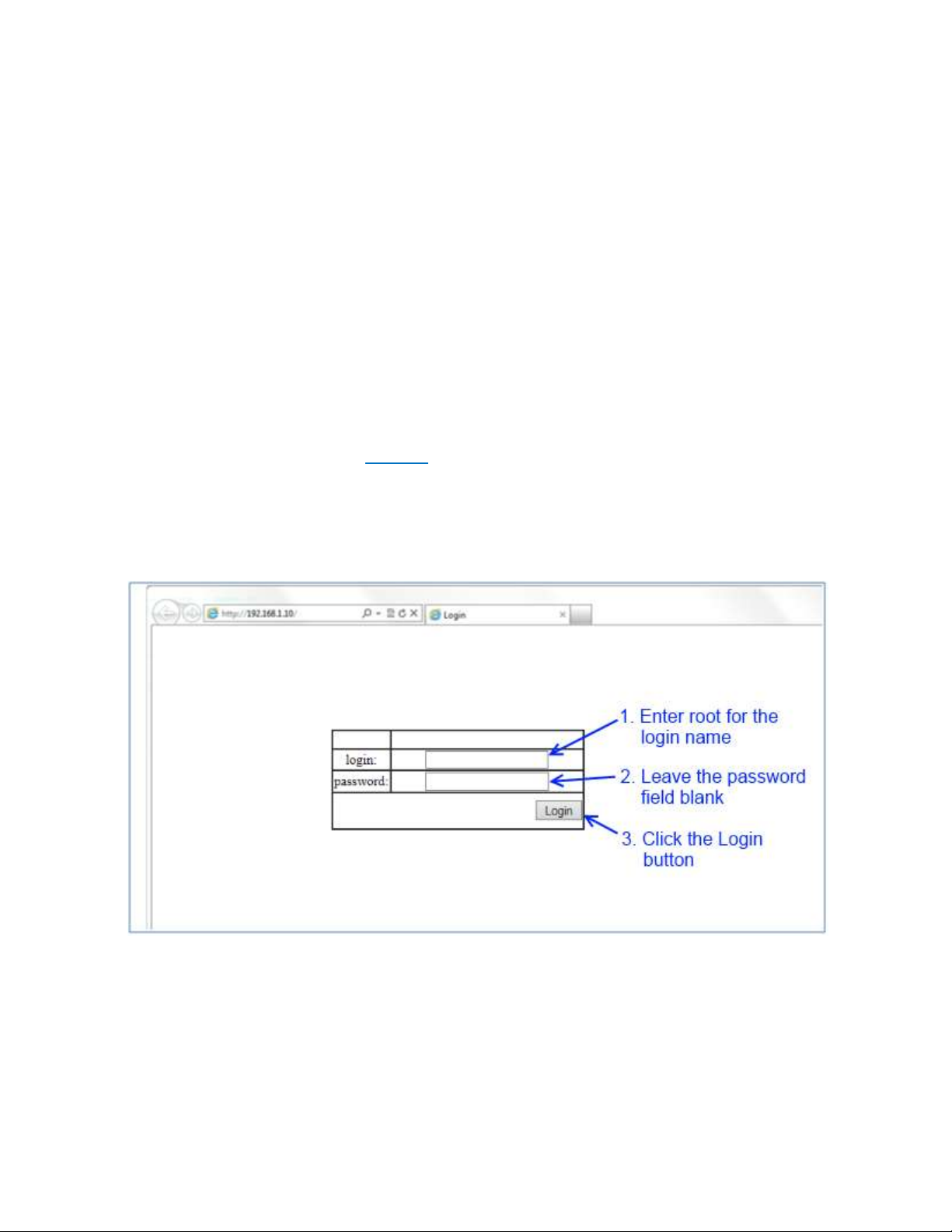
Login Process and Default Credentials
Once a compatible IP address has been assigned to the management computer,
the user is ready to log in to the switch. To log in, type the URL http://192.168.1.10/
into the address field of the browser and hit return. The following will appear in the
browser window (See Figure 1)
The Default Login is root (case sensitive)
There is no password by default
Enter the login name and click the Login button
Figure 1: Login screen
21
EtherWAN Managed Switch Users Guide
Page 22
SETTING THE INITIAL IP ADDRESS
Once logged in the user can now configure the switch per the network requirements. The
two major addressing options are:
Simple IP addressing
Multiple VLAN addressing (See Add an IP to the Management VLAN on page 186).
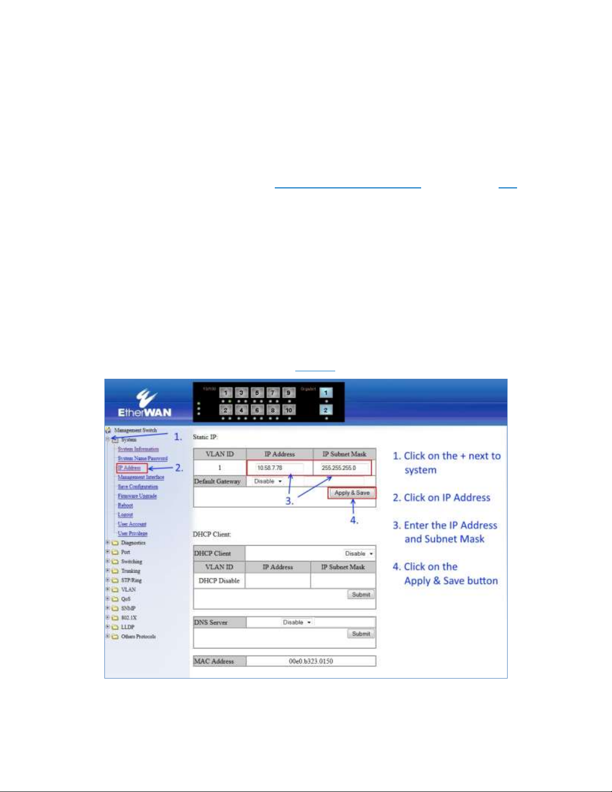
Simple IP Addressing
A new IP address can now be assigned to the switch. From the System Information screen,
go to the left hand navigation menu.
1. Click on the + next to System
2. Click on IP address
3. Enter the desired IP address and subnet mask in the IP Address/Subnet Mask
fields associated with VLAN 1
4. Click the Apply & Save button (See Figure 2)
Figure 2: Assigning an IP address
EtherWAN Managed Switch Users Guide
22
Page 23

CLI COMMAND USAGE
This chapter describes accessing the EtherWAN Managed Switch by using Telnet, SSH, or
serial ports to configure the switch, navigating the Command Line Interface (CLI), typing
keyboard shortcuts, and moving between the levels. This chapter assumes the user has a
working understanding of Telnet, SSH and Terminal emulation applications.
Note: For a serial port connection use a standard DB9F to DB9M Modem Cable. The
default Serial port parameters are 115200, 8 None 1, No Flow Control.
Navigating the CLI Hierarchy
The CLI is organized into a hierarchy of levels. Each level has a group of commands for a
specific purpose. For example, to configure a setting for the VLAN server, one would
navigate to the VLAN level, which is under the config level.
CLI Keyboard Shortcuts
Ctrl + a: place cursor at the beginning of a line
Ctrl + b: backspace one character
Ctrl + d: delete one character
Ctrl + e: place cursor at the end of the line
Ctrl + f: move cursor forward one character
Ctrl + k: delete from the current position to the end of the line
Ctrl + l: redraw the command line
Ctrl + n: display the next line in the history
Ctrl + p: display the previous line in the history
Ctrl + u: delete entire line and place cursor at start of prompt
Ctrl + w: delete one word back
EtherWAN Managed Switch Users Guide
23
Page 24

CLI Command modes
Throughout this manual, each section that has CLI commands relevant to that section
requires that the CLI be in a specific configuration mode. This section shows the main CLI
commands to needed to enter a specific mode.
Global Configuration Mode
To set the EtherWAN Managed Switch to Global Configuration Mode, run the
following commands from the CLI:
1. enable
2. configure terminal
Example:
switch_a>enable
switch_a#configure terminal
switch_a(config)#
MSTP Configuration Mode
To set the EtherWAN Managed Switch to General MSTP configuration mode, run the
following commands from the CLI:
1. enable
2. configure terminal
3. spanning-tree mst configuration
Example:
switch_a>enable
switch_a#configure terminal
switch_a(config)#spanning-tree mst configuration
switch_a(config-mst)#
24
EtherWAN Managed Switch Users Guide
Page 25

Interface Configuration Mode
Interface mode on the EtherWAN Managed Switch is used to configure the Ethernet ports
and VLAN information. Valid interfaces are:
fe<port #> - 100mb ports use fe followed by the port number. Example: fe1
ge<port #> - Gigabit ports use ge followed by the port number. Example: ge1
vlan1.<vlan#> - VLAN’s use vlan. Followed by the VLAN ID. Example: vlan1.10
Example 1 configures 100mb port 1
switch_a>enable
switch_a#configure terminal
switch_a(config)#interface fe1
switch_a(config-if)
Example 2 configures VLAN ID 9
switch_a>enable
switch_a#configure terminal
switch_a(config)#interface vlan1.9
switch_a(config-if)
VLAN Database Configuration Mode
VLAN Database Configuration Mode on the EtherWAN Managed Switch is used to
configure the VLAN settings.
Example:
switch_a>enable
switch_a#configure terminal
switch_a(config)#vlan database
switch_a(config-vlan)#
Saving a Configuration from the CLI
Example:
switch_a>enable
switch_a#write memory
Building configuration.....
[OK]
switch_a#>
EtherWAN Managed Switch Users Guide
25
Page 26

SYSTEM MENU
System Information
The System information link on the Left menu of the Web Configuration page takes you to a
page that shows the following (see Figure 3):
System Name
o The System name is typically used by network administrators. If SNMP is
enabled on the switch, the system name can be found using MIB II
(RFC1213) in the sysName property.
Firmware Version
o If SNMP is enabled on the switch, the Firmware version can be found using
MIB II in the sysDesc property
System Time
o System time can be change using NTP
MAC Address
o The hardware (MAC) address of the Management interface
Default Gateway
o The IP address of your networks Gateway (Typically a Router on your
network)
DNS Server
o The Dynamic Name Server (DNS) for your network
VLAN ID
o One or more listings depending on the number of VLANs defined on the
switch
o Lists VLAN ID, IP address, and subnet mask of the VLAN Interface(s)
Current User Information
o Lists the current the currently logged in user and their user privileges
26
EtherWAN Managed Switch Users Guide
Page 27
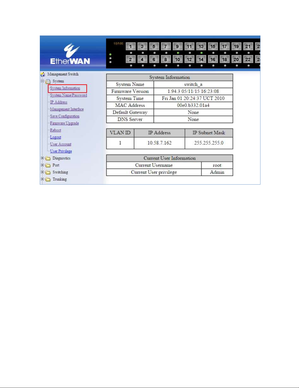
Figure 3: System Information
EtherWAN Managed Switch Users Guide
27
Page 28
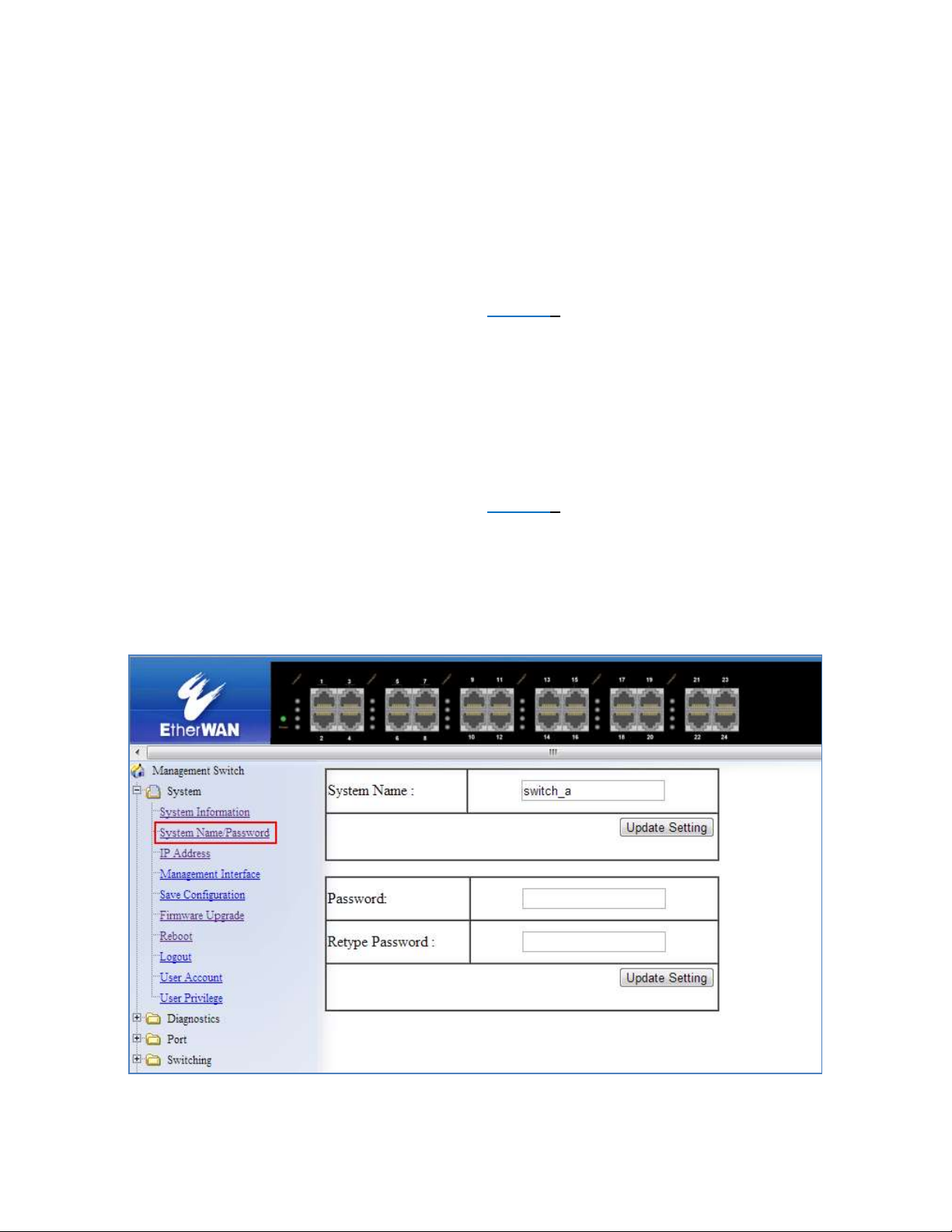
System Name/Password
The System name is typically used by network administrators to make it easier to document
a networks infrastructure and locate equipment on large networks. If SNMP is enabled on
the switch, the system name can be found using MIB II (RFC1213) in the sysName property.
To change the system name:
1. Click on the + next to System.
2. Click on System Name/Password (see Figure 4).
3. Use your mouse to place the cursor in the System Name text box.
4. Replace the existing name with the name you want to assign to the switch.
5. Click on the Update Setting button.
By default there is no password assigned to the switch. To add or change a password:
1. Click on the + next to System.
2. Click on System Name/Password (see Figure 4).
3. Use your mouse to place the cursor in the Password text box.
4. Enter the new password.
5. Retype the password in the Retype Password text box.
6. Click on the Update Setting button below the Retype Password text box.
Figure 4: System Name/Password
EtherWAN Managed Switch Users Guide
28
Page 29

System Name/Password using the CLI
For more information on CLI command usage see CLI Command Usage.
System Name
To set the system name on a switch, use the following CLI commands:
CLI Command Mode: Global Configuration Mode
CLI Command Syntax:
hostname <name>
no hostname
Usage Example 1: Setting a Hostname
switch_a>enable
switch_a#configure terminal
switch_a(config)#hostname switch_a
switch_a(config)#q
switch_a#
Usage Example 2: Removing a Hostname
switch_a>enable
switch_a#configure terminal
switch_a(config)#no hostname
switch_a(config)#q
switch_a#
Password
To enable a password on a switch, use the following CLI commands:
CLI Command Mode: Global Configuration Mode
CLI Command Syntax:
enable password <password>
Usage Example
switch_a>enable
switch_a#configure terminal
switch_a(config)#enable password mypassword
switch_a(config)#q
switch_a#
EtherWAN Managed Switch Users Guide
29
Page 30

Show Switch Model using the CLI
For more information on CLI command usage see CLI Command Usage.
System Name
To set the system name on a switch, use the following CLI commands:
CLI Command Mode: Privileged Exec Mode
CLI Command Syntax:
show integrate product series
Usage Example 1: Setting a Hostname
switch_a>enable
switch_a# show integrate product series
EX27000 series
IP Address
To navigate to the IP Address page:
1. Click on the + next to System
2. Click on IP Address (see Figure 5)
There are 4 settings on this page:
Static IP (see Simple IP Addressing)
DHCP Client
Use this to enable or disable DHCP on a VLAN.
To enable the DHCP Client:
1. Use the drop down box to enable the DHCP client on a particular VLAN
2. Click the Submit Button
Default Gateway
If DHCP is enabled, the gateway setting is controlled by the DHCP server. The
setting will be grayed out and the gateway supplied by the DHCP server will be
displayed. The default gateway setting can be used when using a Static IP address.
To enable the default gateway:
1. Use the dropdown box to enable the default gateway.
2. Type in the default gateway in the Default Gateway text box.
3. Click on the Apply & Save button.
EtherWAN Managed Switch Users Guide
30
Page 31

DNS Server
If DHCP is enabled, the DNS Server setting is controlled by the DHCP server. The
setting will be grayed out and the DNS Server supplied by the DHCP server will be
displayed. The DNS Server setting can be used when using a Static IP address. To
enable the DNS Server:
1. Use the dropdown box to enable the DNS Server.
2. Type in the default gateway in the Default Gateway text box.
3. Click on the Submit button.
Note: After making changes to settings in the IP address section, the
configuration needs to be saved using the System/Save configuration page
(See Save Configuration)
EtherWAN Managed Switch Users Guide
31
Page 32

Figure 5: IP Address
32
EtherWAN Managed Switch Users Guide
Page 33

IP Address - Configuration using the CLI
For more information on CLI command usage see CLI Command Usage.
IP Address
To set the IP address, use the following CLI commands:
CLI Command Mode: Global Configuration Mode
CLI Command Syntax:
ip address <A.B.C.D/M> (IP Address/Mask e.g. 10.0.0.1/8)
no ip address
Note: The Subnet Mask is defined as a Network Prefix instead of the common dotted
decimal (ex. 255.255.255.0).
The most commonly used Network Prefixes are:
/8 – Known as Class A. Also known in dotted decimal as 255.0.0.0
/16– Known as Class B. Also known in dotted decimal as 255.255.0.0
/24– Known as Class C. Also known in dotted decimal as 255.255.255.0
Usage Example 1: Assigning an IP address
switch_a>enable
switch_a#configure terminal
switch_a(config)#ip address 192.168.1.1/24
switch_a(config)#q
switch_a#write memory
Building configuration.....
[OK]
switch_a#q
switch_a#
Usage Example 2: Removing an IP address
switch_a>enable
switch_a#configure terminal
switch_a(config)#no ip address
switch_a(config)#q
switch_a#write memory
Building configuration.....
[OK]
switch_a#q
switch_a#
EtherWAN Managed Switch Users Guide
33
Page 34

Default Gateway
To set the Default Gateway, use the following CLI commands:
CLI Command Mode: Global Configuration Mode
CLI Command Syntax:
ip default-gateway <A.B.C.D>
no ip default gateway
Usage Example 1: Setting the Gateway
switch_a>enable
switch_a#configure terminal
switch_a(config)#ip default-gateway 192.168.1.254
switch_a(config)#q
switch_a#write memory
Building configuration.....
[OK]
switch_a#q
switch_a#
Usage Example 2: Removing the Gateway
switch_a>enable
switch_a#configure terminal
switch_a(config)#no ip default-gateway
switch_a(config)#q
switch_a#write memory
Building configuration.....
[OK]
switch_a#q
switch_a#
34
EtherWAN Managed Switch Users Guide
Page 35

Domain Name Server (DNS)
To set the DNS, use the following CLI commands:
CLI Command Mode: Global Configuration Mode
CLI Command Syntax:
ip dns <A.B.C.D>
no ip dns
Usage Example:
switch_a>enable
switch_a#configure terminal
switch_a(config)#ip dns 192.168.1.253
switch_a(config)#q
switch_a#write memory
Building configuration.....
[OK]
switch_a#q
switch_a#
Usage Example 2: Remove a DNS IP Address
switch_a>enable
switch_a#configure terminal
switch_a(config)#no ip dns
switch_a(config)#q
switch_a#write memory
Building configuration.....
[OK]
switch_a#q
switch_a#
EtherWAN Managed Switch Users Guide
35
Page 36

Enable/Disable DHCP Client on a VLAN
To enable the DHCP client on a VLAN, use the following CLI commands:
CLI Command Mode: Interface Configuration Mode
CLI Command Syntax:
get ip dhcp enable
no get ip dhcp enable
Usage Example – Enable DHCP Client on VLAN2:
switch_a>enable
switch_a#configure terminal
switch_a(config)#interface vlan1.2
switch_a(config-if)#get ip dhcp enable
switch_a(config-if)#q
switch_a(config)#q
switch_a#write memory
Building configuration.....
[OK]
switch_a#q
switch_a#
Enable/Disable Static IP on a VLAN
To set the IP address, use the following CLI commands:
CLI Command Mode: Interface Configuration Mode
CLI Command Syntax:
ip address <A.B.C.D>
no ip address <A.B.C.D>
Usage Example 1 – Enable Static IP on VLAN2:
switch_a>enable
switch_a#configure terminal
switch_a(config)#interface vlan1.2
switch_a(config-if)#ip address 192.168.1.11
switch_a(config-if)#q
switch_a(config)#q
switch_a#write memory
Building configuration.....
[OK]
switch_a#q
switch_a#
36
EtherWAN Managed Switch Users Guide
Page 37

Usage Example 2 – Enable DHCP Client on VLAN2:
switch_a>enable
switch_a#configure terminal
switch_a(config)#interface vlan1.2
switch_a(config-if)#no ip address 192.168.1.11
switch_a(config-if)#q
switch_a(config)#q
switch_a#write memory
Building configuration.....
[OK]
switch_a#q
switch_a#
EtherWAN Managed Switch Users Guide
37
Page 38

Management Interface
To navigate to the Management Interface page:
1. Click on the + next to System
2. Click on Management Interface
The Management Interface configuration page has three settings that allow the user to
configure the methods available to manage the EtherWAN Managed Switch.
HTTPS
HTTPS (Hypertext Transfer Protocol Secure) allows the user to determine what
method, if any, is used to configure the EtherWAN Managed Switch. The default is
unencrypted HTTP (see Figure 6).
To disable the Web interface:
1. Uncheck Http and Https.
2. Click on the Update setting button.
Warning! Once the Submit button is pressed, the Web console will no longer
function. As a safety precaution, the configuration is not saved by default. Rebooting
the EtherWAN Managed Switch will restore the Web Console. To save the
configuration, connect using the new IP address.
To enable the Web Interface:
1. Check HTTP, HTTPS or both
2. Click on the Update Setting button.
3. Save the Configuration (see Save Configuration)
Telnet.
Telnet is a network protocol that allows a remote computer to log into the EtherWAN
Managed Switch to access its CLI (Command Line Interface). The CLI can be access
using Telnet, SSH and the serial port on the EtherWAN Managed Switch. The secure
method of accessing the CLI over a network is SSH.
To enable or disable Telnet:
1. Click the Enable or Disable radio button in the Telnet section on the
Management Interface page (see Figure 6 below)
2. Click on the Update Setting button
3. Save the Configuration (see Save Configuration)
EtherWAN Managed Switch Users Guide
38
Page 39

SSH (Secure Shell)
Secure Shell or SSH is a network protocol that allows data to be exchanged using a
secure channel between two networked devices such as a computer and the
EtherWAN Managed Switch. SSH is disabled by default on the V1.94.3 EtherWAN
Managed Switch.
To enable or disable SSH:
1. Click the Enable or Disable radio button in the SSH section on the
Management Interface page (see Figure 6)
2. Click on the Update Setting button
3. Save the Configuration (see Save Configuration)
Figure 6: Management Interface
39
EtherWAN Managed Switch Users Guide
Page 40

Management Interface Configuration using the CLI
For more information on CLI command usage see CLI Command Usage.
Enabling/Disabling Telnet
To enable or disable telnet, use the following CLI commands:
CLI Command Mode: Global Configuration Mode
CLI Command Syntax:
ip telnet
no ip telnet
Usage Example 1: Enabling Telnet:
switch_a>enable
switch_a#configure terminal
switch_a(config)#ip telnet
switch_a(config)#q
switch_a#write memory
Building configuration.....
[OK]
switch_a#q
switch_a#
Usage Example 2: Disabling Telnet:
switch_a>enable
switch_a#configure terminal
switch_a(config)#no ip telnet
switch_a(config)#q
switch_a#write memory
Building configuration.....
[OK]
switch_a#q
Note: If using Telnet to run the CLI Commands that disable telnet you will lose your
connection. To Disable Telnet using the CLI, use SSH or the RS232 Console port on
the switch.
EtherWAN Managed Switch Users Guide
40
Page 41

Enabling/Disabling SSH
To enable or disable SSH, use the following CLI commands:
CLI Command Mode: Global Configuration Mode
CLI Command Syntax:
ip ssh
no ip ssh
Usage Example 1: Enabling SSH:
switch_a>enable
switch_a#configure terminal
switch_a(config)#ip ssh
switch_a(config)#q
switch_a#write memory
Building configuration.....
[OK]
switch_a#q
switch_a#
Usage Example 2: Disabling SSH:
switch_a>enable
switch_a#configure terminal
switch_a(config)#no ip ssh
switch_a(config)#q
switch_a#write memory
Building configuration.....
[OK]
switch_a#q
Note: If using SSH to run the CLI Commands that disable SSH you will lose your
connection. To Disable SSH using the CLI, use Telnet or the RS232 Console port on
the switch.
EtherWAN Managed Switch Users Guide
41
Page 42

Enabling/Disabling HTTP and/or HTTPS
To enable or disable telnet, use the following CLI commands:
CLI Command Mode: Global Configuration Mode
CLI Command Syntax:
ip http server
ip http secure-server
no ip http server
no ip http secure-server
Usage Example 1: Enabling HTTP:
switch_a>enable
switch_a#configure terminal
switch_a(config)#ip http server
switch_a(config)#q
switch_a#write memory
Building configuration.....
[OK]
switch_a#q
switch_a#
Usage Example 2: Disabling HTTP:
switch_a>enable
switch_a#configure terminal
switch_a(config)#no ip http server
switch_a(config)#q
switch_a#write memory
Building configuration.....
[OK]
switch_a#q
42
EtherWAN Managed Switch Users Guide
Page 43

Usage Example 3: Enabling HTTPS:
switch_a>enable
switch_a#configure terminal
switch_a(config)#ip http secure-server
switch_a(config)#q
switch_a#write memory
Building configuration.....
[OK]
switch_a#q
switch_a#
Usage Example 4: Disabling HTTPS:
switch_a>enable
switch_a#configure terminal
switch_a(config)#no ip http secure-server
switch_a(config)#q
switch_a#write memory
Building configuration.....
[OK]
switch_a#q
EtherWAN Managed Switch Users Guide
43
Page 44

Save Configuration Page
To navigate to the Save Configuration page:
1. Click on the + next to System
2. Click on Save Configuration
The Save Configuration page contains the following configuration functions (see Figure 7):
Save Configuration
To save the currently running configuration to the flash memory on the EtherWAN
Managed Switch:
1. Click the Save Configuration button
2. If the save is successful you will see the message:
Building configuration….. [OK]
Load Configuration
This function is used to load a previously saved configuration. Backing up and
loading a configuration is achieved using a TFTP server.
To load a configuration:
1. Enter the IP address of your TFTP server in the TFTP Server text box
2. Enter the name of the configuration file in the FILE text box
3. Click on the Backup button
4. If the file is successfully loaded the following message will be shown:
Success! System reboot is required!
Backup Configuration
This function is used to back up the current configuration of the EtherWAN Managed
Switch. Backing up the configuration is achieved using a TFTP server such as
TFTPD32.
To back up a configuration:
1. Enter the IP address of your TFTP server in the TFTP Server text box
2. Enter the name of the configuration file in the FILE text box
3. Click on the Backup button
4. If the backup is successful the following message will be shown:
tftp <filename> to ip <ip address> success!!
EtherWAN Managed Switch Users Guide
44
Page 45
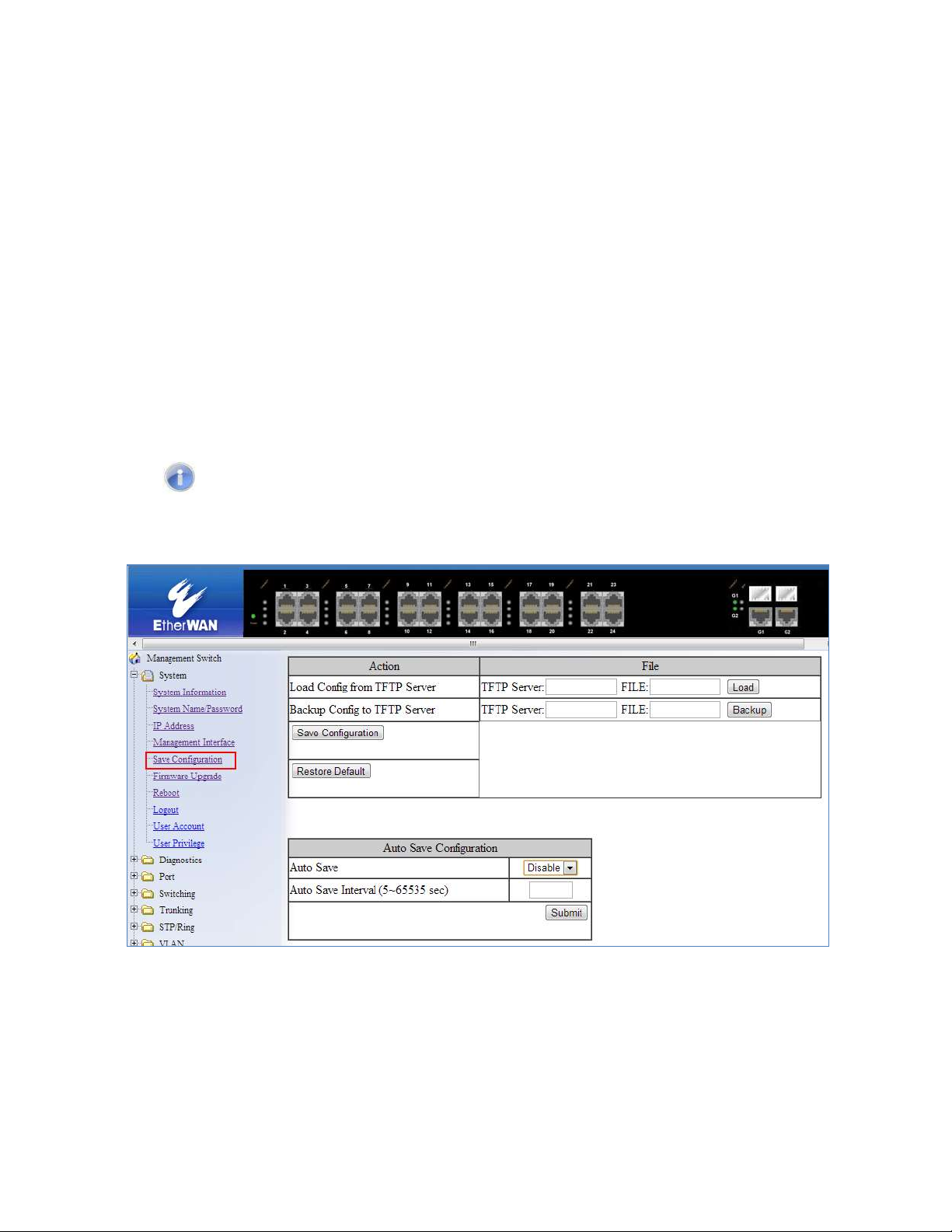
Restore Default
To restore the V1.94.3 EtherWAN Managed Switch to factory defaults:
1. Click on the Restore Default button.
Auto Save
The Auto Save function is used to set the switch to automatically save the
configuration to flash. If the saved configuration is the same as the running
configuration then a save is not made. The Auto Save interval is used to determine
how often the running configuration is checked for changes.
To set the Auto Save function:
1. Click the dropdown box next to Auto Save.
2. Set the Auto Save interval (5~65535 sec)
Note: If a Firewall is running on the PC that is running the TFTP server it may need
to be temporarily disabled.
Figure 7: Save Configuration Page
45
EtherWAN Managed Switch Users Guide
Page 46

Save Configuration Page using the CLI
For more information on CLI command usage see CLI Command Usage.
Saving a Configuration
To save a running configuration, use the following CLI commands:
CLI Command Mode: Global Configuration Mode
CLI Command Syntax:
write memory
Usage Example 1: Saving a Configuration
switch_a>enable
switch_a#write memory
Building configuration.....
[OK]
switch_a#q
switch_a#
Restore Default Settings
To restore the switch to its default settings, use the following CLI commands:
CLI Command Mode: Global Configuration Mode
CLI Command Syntax:
restore default
Usage Example 1: Restoring Defaults
switch_a>enable
switch_a#restore default
switch_a#q
switch_a#
46
EtherWAN Managed Switch Users Guide
Page 47

Load Configuration from a TFTP Server
To Load a Configuration from a TFTP server, use the following CLI commands:
CLI Command Mode: Privileged Exec Mode
CLI Command Syntax:
install config-file <tftpserver_ipaddress> <filename>
Usage Example: Loading a Configuration
switch_a>enable
switch_a#install config-file 192.168.1.100 file_name.txt
switch_a#q
switch_a#
Save Configuration to a TFTP Server
To Save a Configuration to a TFTP server, use the following CLI commands:
CLI Command Mode: Privileged Exec Mode
CLI Command Syntax:
write config-file <tftpserver_ipaddress> <filename>
Usage Example: Saving a Configuration
switch_a>enable
switch_a#write config-file 192.168.1.100 flash.tgz
switch_a#q
switch_a>
47
EtherWAN Managed Switch Users Guide
Page 48

Auto Save Configuration
To set the Auto Save Configuration, use the following CLI commands:
CLI Command Mode: Privileged Exec Mode
CLI Command Syntax:
service auto-config enable
no service auto-config enable
service auto-config interval <number>
Usage Example 1: Enabling Auto Save and setting the interval
switch_a>enable
switch_a#service auto-config enable
switch_a#service auto-config interval 10
switch_a#q
switch_a>
Usage Example 2: Disabling Auto Save
switch_a>enable
switch_a#no service auto-config enable
switch_a#q
switch_a>
EtherWAN Managed Switch Users Guide
48
Page 49

Firmware Upgrade
To navigate to the Firmware Upgrade page:
1. Click on the + next to System
2. Click on Firmware Upgrade
To upgrade the firmware on the EtherWAN Managed Switch, a TFTP server is required. The
firmware file for the V1.94.3 EtherWAN Managed Switch is in a .TGZ or .IMG format. This is
a compressed file; however, it should not be decompressed before updating the V1.94.3
EtherWAN Managed Switch.
To update the firmware on the EtherWAN Managed Switch (see Figure 8):
1. Copy the firmware file to the correct directory for your TFTP server. The correct
directory depends on your TFTP server settings
2. Enter the filename of the firmware in the Filename text box.
3. Enter the IP Address of your TFTP server in the TFTP Server IP text box.
4. Click on the Upgrade button.
5. During the firmware upgrade you will see the following messages. Do not reboot or
unplug the switch until the final message is received.
a. Downloading now, please wait...
b. tftp <filename>.img from ip <ip address> success!!
Install now. This may take several minutes, please
wait...
c. Firmware upgrade success!
Note: If a Firewall is running on the PC that is running the TFTP server it may need to
be temporarily disabled.
EtherWAN Managed Switch Users Guide
49
Page 50

Figure 8: Firmware Upgrade Page
Firmware Update using the CLI
For more information on CLI command usage see CLI Command Usage.
CLI Command Mode: Privileged Exec Mode
CLI Command Syntax:
install image <tftpserver_ipaddress> <filename>
Usage Example:
switch_a>enable
switch_a#install image 192.168.1.100 flash.tgz
switch_a#q
switch_a#
Note: Depending on the firmware being loaded, the extension may not be .tgz. The
Switch does not use the extension to validate firmware.
50
EtherWAN Managed Switch Users Guide
Page 51

Reboot
To navigate to the Reboot page:
1. Click on the + next to System
2. Click on Reboot
To reboot the EtherWAN Managed Switch:
1. Click on the Reboot button.
2. Click OK on the popup message.
Reboot using the CLI
For more information on CLI command usage see CLI Command Usage.
CLI Command Mode: Privileged Exec Mode
CLI Command Syntax:
reload
Usage Example:
switch_a>enable
switch_a#reload
switch_a#q
switch_a#
Logout
To logout of the Web Configuration Console:
1. Click on the + next to System
2. Click on Logout
Logout from the CLI
CLI Command Mode: Exec mode or Privileged Exec Mode
CLI Command Syntax:
logout
EtherWAN Managed Switch Users Guide
51
Page 52

User Account Page
To navigate to the User Account page:
1. Click on the + next to System
2. Click on User Account
From the User Account page, multiple users can be setup with different access privileges to
the switch. There are two modes that can be used, Single-User or Multi-User.
Changing the User Mode
To set the user mode (see Figure 9):
1. Select Single-User, Multi-User or Radius-User in the dropdown box in the MultiUser Mode section. See IEEE 802.1X for more information on setting up Radius
Authentication.
2. Click on the Update Setting button.
3. Click OK on the Popup message that appears.
Note: Changing the user mode saves the configuration and reboots the switch
Figure 9: User Mode
EtherWAN Managed Switch Users Guide
52
Page 53

Creating a New User
To create a new user (see Figure 10):
1. Choose the Create option from the dropdown list next to the User Account row
heading.
2. Enter a User Name (case sensitive) for the new user in the User Name text box.
3. Enter a Password for the new user in the Password text box.
4. Re-enter the Password in the Confirm Password text box.
5. Select a Privilege Level from the dropdown list next to the Privilege Level row
heading. For more information on Privilege levels see the User Privilege
Configuration.
6. Click on the Update button.
7. Save the configuration (See the Save Configuration Page)
Figure 10: Creating Users
53
EtherWAN Managed Switch Users Guide
Page 54

Changing an Existing User Account
To make modifications to an existing user account:
1. Choose an existing user from the dropdown list next to the User Account row
heading (see Figure 11).
2. Change the password and/or access level following the steps in Creating a New
User.
3. To delete an existing user, select the user as in step 1 and then click on the Delete
button (see Figure 12).
Figure 11: Selecting an Existing User Account
Figure 12: Deleting a User Account
EtherWAN Managed Switch Users Guide
54
Page 55

User Privilege Configuration
To navigate to the User Privilege page:
1. Click on the + next to System.
2. Click on User Privilege.
There are 3 different Privilege levels on the EtherWAN Managed Switch.
Admin – Has access to all configuration and administration of the switch.
Technician – Configurable by Admin – By default no configuration ability is given.
Operator – Configurable by Admin – By default no configuration ability is given.
The User Privilege Configuration page allows specific configuration and/or administration
levels to be assigned or removed from the Technician and Operator user roles.
Note: For each function, an operator’s privilege cannot be higher than a technician's
To configure the privileges for each user access level, follow the below steps:
1. For each of the configuration options listed under Web function \ User Privilege
(see Figure 13), select the proper privilege from the drop-down list under the
appropriate user access level (Technician or Operator). The valid options are:
a. Show, Hidden, Read-Only, Read-Write
2. Click on the Update button at the bottom of the page.
3. Save the configuration (see Save Configuration)
EtherWAN Managed Switch Users Guide
55
Page 56

Figure 13: User Privilege Page
EtherWAN Managed Switch Users Guide
56
Page 57

User Account Settings using the CLI
For more information on CLI command usage see CLI Command Usage.
Multi-User Mode
To enable the multi-user feature, use the following CLI commands:
CLI Command Mode: Line Configuration Mode
CLI Command Syntax: login local
Usage Example:
switch_a>enable
switch_a#configure terminal
switch_a(config)#line console 0
switch_a(config-line)#login local
% Switching Single/Multi/Radius-User mode need to reboot the
switch to take effect!
switch_a(config-line)#q
switch_a(config)#q
switch_a#
Single User Mode
To enable the single-user feature, use the following CLI commands:
CLI Command Mode: Line Configuration Mode
CLI Command Syntax: login
Usage Example:
switch_a>enable
switch_a#configure terminal
switch_a(config)#line console 0
switch_a(config-line)#login
% Switching Single/Multi/Radius-User mode need to reboot the
switch to take effect!
switch_a(config-line)#q
switch_a(config)#q
switch_a#
EtherWAN Managed Switch Users Guide
57
Page 58

Radius User Mode
To enable the radius-user feature, use the following CLI commands:
CLI Command Mode: Line Configuration Mode
CLI Command Syntax: login radius
Usage Example:
switch_a>enable
switch_a#configure terminal
switch_a(config)#line console 0
switch_a(config-line)#login radius
% Switching Single/Multi/Radius-User mode need to reboot the
switch to take effect!
switch_a(config-line)#q
switch_a(config)#q
switch_a#
EtherWAN Managed Switch Users Guide
58
Page 59

Creating a New User
To create a new user, use the following CLI commands:
CLI Command Mode: Global Configuration Mode
CLI Command Syntax:
username <user name-4 to 16 characters> privilege
<admin|operator|technician> password < 8|blank> <password-1 to 35
characters>
Note: The optional <8> CLI command after the CLI command password is
used to specify that the password should be displayed in encrypted form in the
configuration file.
Usage Example:
switch_a>enable
switch_a#configure terminal
switch_a(config)#username user1 privilege operator password 1234
switch_a(config)#username user1 privilege operator password 8 1234
switch_a(config)#username user2 privilege technician password 4321
switch_a(config)#username user2 privilege technician password 8 4321
switch_a(config)#username user3 privilege admin password 5678
switch_a(config)#username user3 privilege admin password 8 5678
switch_a(config)#q
switch_a#
Permissions
Permissions must be set using the Web GUI. See User Privilege Configuration.
EtherWAN Managed Switch Users Guide
59
Page 60

DIAGNOSTICS
Utilization
To navigate to the Utilization page:
1. Click on the + next to Diagnostics.
2. Click on Utilization.
The Utilization page shows (see Figure 14):
CPU Utilization – Current and Max Utilization
Memory Utilization – Total, Used and Free Memory
Figure 14: Utilization Page
60
EtherWAN Managed Switch Users Guide
Page 61

System Log
To navigate to the System Log page:
1. Click on the + next to Diagnostics.
2. Click on System Log.
The System Log shows the date and time of port links going up or down (see Figure 15)
Figure 15: System Log
System log using CLI command
For more information on CLI command usage see CLI Command Usage.
CLI Command Mode: Exec Mode or Privileged Exec Mode
CLI Command Syntax:
show system-log
Usage Example:
switch_a#show system-log
switch_a#q
switch_a#
EtherWAN Managed Switch Users Guide
61
Page 62

Remote Logging
To navigate to the Remote Logging page:
1. Click on the + next to Diagnostics.
2. Click on Remote Logging.
Remote Logging to a Syslog server allows administrators to log important system and
debugging information. The Remote Logging configuration page allows reporting to a Syslog
server to be enabled or disabled as well as management of a list of Syslog servers to report
to (see Figure 16).
To configure the Remote Logging on the EtherWAN Managed Switch:
1. Click on the Enable or Disable radio button under Remote Logging.
2. Click on the Update Setting button.
To add a Syslog server:
1. Enter the IP Address of the Syslog Server in the Syslog Server IP text box.
2. Click on the Add Syslog Server button.
To delete a Syslog server from the list of servers currently on the switch:
1. Select the Syslog server from the Drop down box
2. Click on the Delete Syslog Server button
EtherWAN Managed Switch Users Guide
62
Page 63

Figure 16: Remote Logging Page
EtherWAN Managed Switch Users Guide
63
Page 64

Remote Logging using CLI commands
For more information on CLI command usage see CLI Command Usage.
Enable/Disable Remote Logging
CLI Command Mode: Global Configuration Mode
CLI Command Syntax:
remote-log enable
no remote-log enable
Usage Example 1: Enable Remote Logging
switch_a>enable
switch_a#remote-log enable
switch_a#q
switch_a#
Usage Example 2: Disable Remote Logging
switch_a>enable
switch_a#no remote-log enable
switch_a#q
switch_a#
Add/Delete a Remote Logging Host
CLI Command Mode: Global Configuration Mode
CLI Command Syntax:
remote-log add <ip_address>
remote-log del <ip_address>
remote-log del all
Usage Example 1: Add a Remote Logging Host
switch_a>enable
switch_a#remote-log add 192.168.1.100
switch_a#q
switch_a#
Usage Example 2: Delete a Remote Logging Host
switch_a>enable
switch_a#remote-log del 192.168.1.100
switch_a#q
switch_a#
EtherWAN Managed Switch Users Guide
64
Page 65

ARP Table
To navigate to the ARP Table page:
1. Click on the + next to Diagnostics.
2. Click on ARP Table.
The ARP Table page shows ARP (Address Resolution Protocol) entries that are stored in
the Switches ARP Table. This is useful for System Administrators for troubleshooting
purposes. The information shown is:
IP Address of the listed device
Hardware Address – For Ethernet devices this will always be 1.
Flags
o 2 = Device responded to ARP Request
o 0 = No response to ARP Request
Hardware Address – MAC Address of the listed device
VLAN – The VLAN that the listed device is on
Figure 17: ARP Table
65
EtherWAN Managed Switch Users Guide
Page 66

ARP Table using CLI Commands
For more information on CLI command usage see CLI Command Usage.
CLI Command Mode: Global Configuration Mode
CLI Command Syntax:
show arp-table
Usage Example:
switch_a>enable
switch_a#show arp-table
IP address HW type Flags HW address Mask VLAN
10.58.7.130 1 2 00:50:B6:65:2A:22 * 1
switch_a#q
switch_a#
EtherWAN Managed Switch Users Guide
66
Page 67

Route Table
To navigate to the Route Table page:
1. Click on the + next to Diagnostics.
2. Click on Route Table.
The Route Table lists the routes to network destinations and metrics (distances) that are
associated with those routes. The Route Table contains information about the topology of
the network around it.
Figure 18: Route Table
Route Table Using CLI Commands
For more information on CLI command usage see CLI Command Usage.
CLI Command Mode: Global Configuration Mode
CLI Command Syntax:
show route-table
Usage Example:
switch_a>enable
switch_a#show route-table
Destination Gateway Genmask Flags Metric Ref Use VLAN
10.58.7.0 0.0.0.0 255.255.255.0 U 0 0 0 1
switch_a#q
switch_a#
EtherWAN Managed Switch Users Guide
67
Page 68
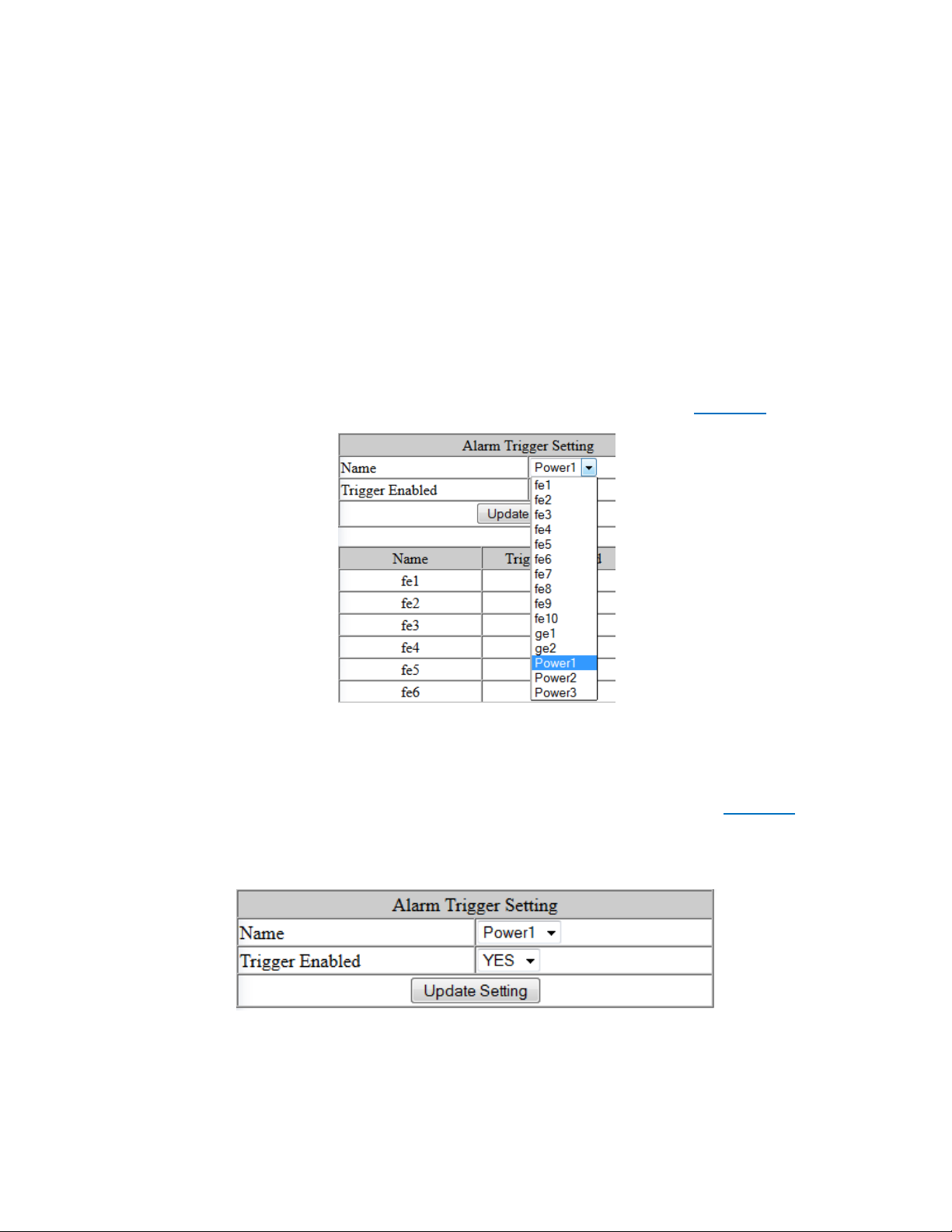
Alarm Setting
This setting applies only to Switch models that have a hardware relay.
To navigate to the Alarm Setting page:
1. Click on the + next to Diagnostics.
2. Click on Alarm Setting.
The Alarm Setting page allows users to define Ethernet port Link-down and Power failure
alarms for triggering an alarm using the relay on the switch.
To configure an Ethernet port or Power input:
1. Select an Ethernet port or Power input from the dropdown box (see Figure 19).
Figure 19: Alarm Trigger
3. Select YES or NO from the dropdown box next to Trigger Enabled (see Figure 20).
4. Click Update Setting to save any changes made.
Figure 20: Trigger Enable
EtherWAN Managed Switch Users Guide
68
Page 69

PORT
Configuration
To navigate to the Configuration page:
1. Click on the + next to Port.
2. Click on Configuration.
Port configuration contains such useful features as flow control, port speed, and duplex
settings. Some users will find these settings very valuable such as when the switch is
connect to a latency-critical device such as a VOIP phone or IP camera or video multiplexor.
In these cases and others the ability to alter the port settings can make the difference
between a poorly responding device and one that functions without loss of data or clarity.
.The Configuration page shows (see Figure 21):
Port Number – fe(n) for 100mb ports and ge(n) for Gigabit ports
Link Status – Operational State of the Port’s Link (Read-Only)
Port Description – User-supplied Port Description
Admin Setting – Administratively Enable or Disable the Port.
Speed – Speed and Duplex Settings for Port.
Flow Control – State of Flow Control for the Port.
To provide a description to a port on the EtherWAN Managed Switch:
1. Click in the Description text box for the appropriate port.
2. Type in the description of the port.
3. Click on the Submit button.
To enable or disable a port on the EtherWAN Managed Switch:
1. Click on the drop-down box under Admin Setting and select either Link Up or Link
Down.
2. Click on the Submit button.
69
EtherWAN Managed Switch Users Guide
Page 70

To set the Port Speed and/or Port Duplex Settings on the EtherWAN Managed Switch:
1. Click on the drop-down box under Speed and select the desired port speed / duplex
settings for that port. Please note, not all port types will have the same options. For
example, 100Mb fiber ports will typically be limited to a single option of 100M/FD
(100Mbps and Full Duplex) while running 1Gb UTP ports will have six options for
speed/duplex.
2. Click on the Submit button.
To enable or disable a port’s Flow Control settings on the EtherWAN Managed Switch:
1. Click on the drop-down box under Flow Control and select either Enable or Disable.
2. Click on the Submit button.
Figure 21: Port Configuration
70
EtherWAN Managed Switch Users Guide
Page 71

Port Status
To navigate to the Port Status page:
1. Click on the + next to Port.
2. Click on Port Status.
This page is a read-only page that lists the settings described in the previous section. It is
useful if all the user intends to do is read the values of the port settings, not modify the port
settings. .The Port Status page shows (see Figure 22):
Port Number – fe(n) for 100mb ports and ge(n) for Gigabit ports
Link Status – Operational State of the Port’s Link
Medium type – Indicates whether the cable is copper or fiber
Port Description – User-supplied Port Description
Admin Setting – Administratively State of the Port
Speed – Speed and Duplex Settings for Port
Flow Control – State of Flow Control for the Port
Figure 22: Port Status
Rate Control
To navigate to the Rate Control page:
EtherWAN Managed Switch Users Guide
71
Page 72

1. Click on the + next to Port.
2. Click on Rate Control.
The Rate Control page allows the user to set the maximum throughput on a port or ports on
both packets entering the port (from the connected device) or packets leaving the port.
The Ingress text box controls the rate of data traveling into the port while the Egress text
box controls the rate of data leaving the port.
Note: Entries will be rounded down to the nearest acceptable rate value. If the value
entered is below the lowest acceptable value then the lowest acceptable value will be
used.
The Rate Control page is shown below (see Figure 23):
To provide either an ingress or egress rate control for a port on the EtherWAN Managed
Switch:
1. Click in the Ingress or Egress Text Box for the appropriate port.
2. Type in the ingress/egress rate for the port according to the values listed above.
3. Click on the Update Setting button.
Figure 23: Rate Control
EtherWAN Managed Switch Users Guide
72
Page 73

RMON Statistics
To navigate to the RMON Statistics page:
1. Click on the + next to Port.
2. Click on RMON Statistics.
RMON Statistics gives a detailed listing of the types and quantity of packets that a particular
port has seen since the last reboot of the switch (see Figure 24).
To view the RMON statistics for a particular port on the EtherWAN Managed Switch:
1. Click on the link to the port at the top of the RMON Statistics page.
To clear the RMON statistics for a particular port on the EtherWAN Managed Switch:
1. Click on the link to the port at the top of the RMON Statistics page.
2. Click on the Clear button at the bottom of the page.
3. The statistics for the port will update every ten seconds.
Pay particular attention to the values for CRC/Alignment errors and collisions. Nonzero
values for these fields can indicate that a port speed or duplex mismatch exists on the port.
Figure 24: RMON Page
EtherWAN Managed Switch Users Guide
73
Page 74

Per Port VLAN Activities
To navigate to the Per Port VLAN Activities page:
1. Click on the + next to Port.
2. Click on Per Port VLAN Activities.
This is a read-only page that will allow the user to see what devices are connected to a
particular port and the vlan associated with that device and port.
To clear the MAC addresses for a particular port on the EtherWAN Managed Switch (see
Figure 25):
1. Click on the link to the port at the top of the Per Port VLAN Activities page.
2. Click on the Clear MAC button at the bottom of the page.
3. The statistics for the port will update every ten seconds.
Figure 25: Port VLAN Activities
74
EtherWAN Managed Switch Users Guide
Page 75

Port Security
This feature is not available on all models.
To navigate to the Port Security page:
1. Click on the + next to Port.
2. Click on Port Security.
The Port Security submenu allows the user to control access to the ports on the switch
based on the source MAC addresses of the network devices.
To Add a MAC Address to a port:
1. Select the Enable or Disable from the Mode column for the port you want to
configure.
2. Enter the MAC Address of the device you want to connect to the port
3. Click Update Setting.
To remove a MAC Address from a port
1. Select the MAC Address from the Dropdown list next to the port that you want to
configure (see Figure 26)
2. Click on Update Setting.
Figure 26: Port Security
EtherWAN Managed Switch Users Guide
75
Page 76

Port Configuration Examples Using CLI Commands
For more information on CLI command usage see CLI Command Usage.
Setting the Port Description
To provide a description of a port use the CLI commands below:
CLI Command Mode: Interface Configuration Mode
CLI Command Syntax: description <description text>
Usage Example:
switch_a>enable
switch_a#configure terminal
switch_a(config)#int fe1
switch_a(config-if)#description A_Port_Description
switch_a(config)#q
switch_a(config)#q
switch_a#
Enable or Disable a Port
To administratively enable or disable a port use the CLI commands below:
CLI Command Mode: Interface Configuration Mode
CLI Command Syntax:
shutdown
no shutdown
Usage Example 1: Disabling a port:
switch_a>enable
switch_a#configure terminal
switch_a(config)#int fe1
switch_a(config-if)#shutdown
switch_a(config)#q
switch_a(config)#q
switch_a#
Usage Example 2: Enabling a port:
EtherWAN Managed Switch Users Guide
76
Page 77

switch_a>enable
switch_a#configure terminal
switch_a(config)#int fe1
switch_a(config-if)#no shutdown
switch_a(config)#q
switch_a(config)#q
switch_a#
Setting the Port Speed
To set the port speed for a port use the CLI commands below:
CLI Command Mode: Interface Configuration Mode
CLI Command Syntax: bandwidth <1-10000000000 bits> (usable units : k, m, g)
Usage Example:
switch_a>enable
switch_a#configure terminal
switch_a(config)#int fe1
switch_a(config-if)#bandwidth 100m
switch_a(config)#q
switch_a(config)#q
switch_a#
Setting Port Duplex
To set the duplex for a port use the CLI commands below:
CLI Command Mode: Interface Configuration Mode
CLI Command Syntax: duplex <full | half | auto>
Usage Example:
switch_a>enable
switch_a#configure terminal
switch_a(config)#int fe1
switch_a(config-if)#duplex full
switch_a(config)#q
switch_a(config)#q
switch_a#
EtherWAN Managed Switch Users Guide
77
Page 78

Enable or Disable Port Flow Control
To enable or disable flow control for a port use the CLI commands below:
CLI Command Mode: Interface Configuration Mode
CLI Command Syntax: flowcontrol on
Usage Example:
switch_a>enable
switch_a#configure terminal
switch_a(config)#int fe1
switch_a(config-if)#flowcontrol on
switch_a(config)#q
switch_a(config)#q
switch_a#
Display Port Status
To display the port status for a port use the CLI commands below:
CLI Command Mode: Privileged Exec Mode
CLI Command Syntax: show interface <ifname>
Usage Example:
switch_a>enable
switch_a#show interface fe1
Setting a Ports Rate Control
To set a ports rate control use the CLI commands below:
CLI Command Mode: Interface Configuration Mode
CLI Command Syntax: rate-control <ingress | egress> value <value in kbps>
Usage Example:
switch_a>enable
switch_a#configure terminal
switch_a(config)#int fe1
switch_a(config-if)#rate-control ingress value 100000
switch_a(config)#q
switch_a(config)#q
switch_a#
78
EtherWAN Managed Switch Users Guide
Page 79

Display a Ports RMON Statistics
To display a ports RMON statistics use the CLI commands below:
CLI Command Mode: Privileged Exec Mode
CLI Command Syntax: show interface statistics <interface name>
Usage Example:
switch_a>enable
switch_a#show interface statistics fe1
switch_a#
Display a Ports VLAN Activities
To display a port’s VLAN activities use the CLI commands below:
CLI Command Mode: Privileged Exec Mode
CLI Command Syntax: show bridge interface <interface name>
Usage Example:
switch_a>enable
switch_a#show bridge interface fe1
switch_a#
Setting MAC Port Security
To enable MAC port security use the CLI commands below:
CLI Command Mode: Interface Configuration Mode
CLI Command Syntax: port-security enable
Usage Example:
switch_a>enable
switch_a#configure terminal
switch_a(config)#int fe1
switch_a(config-if)# port-security enable
switch_a(config)#q
switch_a(config)#q
switch_a#
79
EtherWAN Managed Switch Users Guide
Page 80

To disable MAC port security use the CLI commands below:
CLI Command Mode: Interface Configuration Mode
CLI Command Syntax: no port-security enable
Usage Example:
switch_a>enable
switch_a#configure terminal
switch_a(config)#int fe1
switch_a(config-if)# no port-security enable
switch_a(config)#q
switch_a(config)#q
switch_a#
To set the allowed MAC addresses use the CLI commands below:
CLI Command Mode: Interface Configuration Mode
CLI Command Syntax: port-security allowed-address <value>
(in hex format. Ex. 00aa.0062.c609)
Usage Example:
switch_a>enable
switch_a#configure terminal
switch_a(config)#int fe1
switch_a(config-if)# port-security allowed-address 00aa.0062.c609
switch_a(config)#q
switch_a(config)#q
switch_a#
To delete an allowed MAC address use the CLI commands below:
CLI Command Mode: Interface Configuration Mode
CLI Command Syntax: no port-security allowed-address <value>
(in hex format. Ex. 00aa.0062.c609)
Usage Example:
switch_a>enable
switch_a#configure terminal
switch_a(config)#int fe1
switch_a(config-if)# no port-security allowed-address 00aa.0062.c609
switch_a(config)#q
switch_a(config)#q
switch_a#
EtherWAN Managed Switch Users Guide
80
Page 81

SWITCHING
Bridging
To learn MAC addresses, a switch reads all packets that it detects on the LAN or on the
local VLAN, looking for MAC addresses of sending nodes. It places these addresses into its
Ethernet Switching table, along with the interface on which the traffic was received and the
time when the address was learned. When the switch receives traffic on an interface, it
searches the Ethernet switching table for the MAC address of the destination. If the MAC
address is not found, the traffic is flooded out all of the other interfaces associated with the
VLAN. If traffic is received on an interface that is associated with VLAN 1 and there is no
entry in the Ethernet switching table for VLAN 1, then the traffic is flooded to all access and
trunk interfaces that are members of VLAN 1.
Flooding allows the switch to learn about destinations that are not yet in its Ethernet
switching table. If a certain destination MAC address is not in the Ethernet switching table,
the switch floods the traffic to all interfaces except the interface on which it was received.
When the destination node receives the flooded traffic, it sends an acknowledgment packet
back to the switch, allowing the switch to learn the MAC address of the node and to add the
address to its Ethernet switching table.
The switch uses a process called aging to keep the Ethernet switching table current. For
each MAC address in the Ethernet switching table, the switch records a timestamp of when
the information about the network node was learned. Each time the switch detects traffic
from a MAC address that is in its Ethernet switching table, it updates the timestamp of that
MAC address. A timer on the switch periodically checks the timestamp, and if it is older than
the value set for mac-table-aging-time, the switch removes the node's MAC address from
the Ethernet switching table. This aging process ensures that the switch tracks only active
MAC addresses on the network and that it is able to flush out from the Ethernet switching
table MAC addresses that are no longer available.
The user can configure:
How long MAC addresses remain in the Ethernet switching table
Add a MAC address permanently to the switching table
Prevent a MAC address from ever being registered in the switching table.
To navigate to the Bridging page:
1. Click on the + next to Switching.
2. Click on Bridging.
EtherWAN Managed Switch Users Guide
81
Page 82

Aging Time
The Aging Time value is a global value and represents the time that a networked device’s
MAC address will live in the switch’s memory before being removed. The default value is
300s (5 minutes) (see Figure 27).
To update the Aging Time value on the EtherWAN Managed Switch:
1. Click in the Error Disable Recovery text box at the top of the Port Security DynamicMAC page.
2. Type in the desired value. Values can be from 0 to 65535 seconds. A value of 0
indicates that the port is not to return to normal operating condition until an
administrator resets the port or the switch is restarted.
3. Click on the Update Setting button.
Threshold Level
The Threshold Level setting is a per port value. A traffic storm occurs when packets flood
the LAN, creating excessive traffic and degrading network performance. The traffic storm
control feature prevents LAN ports from being disrupted by a broadcast or multicast traffic
storm on physical interfaces. A Threshold is set to determine when the switch will react to
Broadcasts and/or Multicasts.
To set the Threshold level per port:
1. Type in the desired value. Values can be from 0.1 to 100. This value is a percentage
of allowable broadcast traffic for this port. Once this percentage of traffic is
exceeded, all broadcast traffic beyond this percentage is dropped.
2. Click on the Update Setting button.
Storm Control Type
The Storm Control Enabled Type setting is a per port value. The Storm Control Enabled
Type allows users to determine the type of storm control to be used by the switch.
To set the Storm Control Enabled Type:
1. Select the check box next to Broadcast and/or DFL-Multicast for the port that
needs to be changed
2. Click on the Update Setting button.
EtherWAN Managed Switch Users Guide
82
Page 83

Port Isolation
The Port Isolation setting is a per port value. Port Isolation can be used to isolate a port or
ports so that only the isolated ports can communicate with one another (see Figure 27).
To update the Port Isolation value for a port on the EtherWAN Managed Switch:
1. Click on the Port Isolation drop-down box for the port to be isolated.
2. Select the value enable on the Port Isolation drop-down box.
3. Click on the Update Setting button.
4. Repeat as necessary for all ports that are to be isolated.
Block Multicast
The Block Multicast setting is a per port value. Block Multicast is a straight-forward
description of a feature that is used to block multicast traffic from accessing a port (see
Figure 27).
To update the Block Multicast value for a port on the EtherWAN Managed Switch:
1. Click on the Block Multicast drop-down box for the port to be isolated.
2. Select the value enable on the Block Multicast drop-down box.
3. Click on the Update Setting button.
4. Repeat as necessary for all ports that are to have multicast traffic blocked.
EtherWAN Managed Switch Users Guide
83
Page 84

Figure 27: Bridging
EtherWAN Managed Switch Users Guide
84
Page 85

Loopback Detect
Loopback detection is quite simply the ability of the switch to detect when a port on the
switch has been connected directly (or “looped back”) to another port on the switch. This
configuration would likely lead to a broadcast storm on the switch which would cause
network performance to suffer. Loopback detection offers the ability of the switch to detect
this condition and shutdown the loop-backed port before any disruption of network traffic
occurs.
To navigate to the Loopback Detect page:
1. Click on the + next to Switching.
2. Click on Loopback Detect.
Loopback Detection (Global)
To globally enable the Loopback Detect feature of the EtherWAN Managed Switch (see
Figure 28):
1. Click on the Loopback Detect drop-down box.
2. Select Enable from the drop down list.
3. Click on the Update Setting button.
Loopback Detect Action
To change the action that the switch takes when a loopback condition is detected (see
Figure 28):
1. Choose an action from the Loopback Detect Action dropdown list. The available
options are None and Error Disable.
2. Click on the Update Setting button.
Loopback Detect Recovery Time
To change the length of time that the Loopback Detect Action will stay in effect (see Figure
28):
1. Enter a value in the text box next to Error Disable Recovery. Valid values range
from 0 to 65535 seconds.
2. Click on the Update Setting button.
EtherWAN Managed Switch Users Guide
85
Page 86

Polling Interval
To change the polling interval of the Loopback Detect function (see Figure 28):
1. Enter a value in the text box next to Interval. Valid values range from 1 to 65535
seconds.
2. Click on the Update Setting button.
Figure 28: Loopback Detection
EtherWAN Managed Switch Users Guide
86
Page 87

Loopback Detection (Per Port)
To enable Loopback Detection for a particular port or ports on the EtherWAN Managed
Switch (see Figure 29):
1. Select the value Enable from the Mode drop down list for a port on the Loopback
Detect page.
2. Click on the Update Setting button.
Figure 29: Loopback Detection (port)
87
EtherWAN Managed Switch Users Guide
Page 88

Storm Detect
The Storm Detect feature allows the switch to be configured to disable a port that is
receiving a large number of Broadcast and/or Multicast packets. The switch can monitor for
packets and take action based on percentage of bandwidth utilization or number of packets
per second.
To navigate to the Storm Detect page:
1. Click on the + next to Switching.
2. Click on Storm Detect.
Enable/Disable Storm Detection
1. Enable or Disable Storm Detection by Clicking on the drop down box in the StormDetect Configuration box (see Figure 30).
2. Set the Storm Detect interval to a number between 2 and 65535 seconds. The
Default value is 10 seconds.
3. Set the Storm-Detect errdisable-recovery time to value between 0 and 65535
seconds. The Default is 0 (disabled). This value determines if the switch should reenable the port after the specified value or leave the port disabled.
Figure 30: Storm Detect – Global
4. Set the By Utilization(%) for each port in the Storm-Detect Per Port Configuration
box (see Figure 31). The default is 0 (not limited). Setting this to a value between 1
and 100 will cause the port to be disabled when the defined percentage of bandwidth
is reached.
5. Set the type of packet to be monitored in the Dropdown box under By Broadcast /
Multicast+Broadcast Packets Per Second. Set the value to BC to monitor
Broadcast packets and BC-MC to monitor both Broadcast and Multicast packets.
EtherWAN Managed Switch Users Guide
88
Page 89

6. Set the number of packets per second to a value between 0 and 1000000 packets.
The default is 0 (not limited).
Figure 31: Storm Detect – Per Port
89
EtherWAN Managed Switch Users Guide
Page 90

Static MAC Entry
Occasionally, it may be useful to specify a MAC address on a particular port and VLAN
rather than adjusting the ageing time for the entire switch. Alternatively, it is also possible
and even desirable to prevent a MAC address from ever being registered with a switch.
These features are offered under the Static MAC Entry menu.
To navigate to the Static MAC Entry menu:
1. Click on the + next to Switching.
2. Click on Static MAC Entry.
Adding a Static MAC Address to a Port
To add a static MAC entry for a particular port (see Figure 32):
1. Enter the MAC address for end the corresponding port’s text box. The format of the
MAC address should be in the form aaaa:bbbb:cccc).
2. Select the VLAN that this MAC address is associated with from the VLAN ID drop
down list for the port.
3. Click on the Submit button.
Figure 32: MAC Static Entry
EtherWAN Managed Switch Users Guide
90
Page 91

Removing a Static MAC Address from a Port
To remove a static MAC entry for a particular port (see Figure 33):
1. For a particular port, select the MAC address to be deleted from the Delete MAC
Address drop down box.
2. Click on the Submit button.
Figure 33: Removing a Static MAC
Adding a MAC to the Static-MAC-Entry Discard Table
To add a MAC address to the Static-MAC-Entry Discard table (see Figure 34):
1. Enter a MAC address in the form “0000.1234.abdc” in the Add MAC Address text
box of the Static-MAC-Entry-Discard section.
2. Select the VLAN associated with the MAC address.
3. It should be noted that while static MAC address for forwarding are associated with
the switch on a per-port basis. Static MAC discards are associated with the switch for
all ports.
4. Click on the Submit button.
Figure 34: Adding a MAC – Static-MAC-Entry Table
EtherWAN Managed Switch Users Guide
91
Page 92
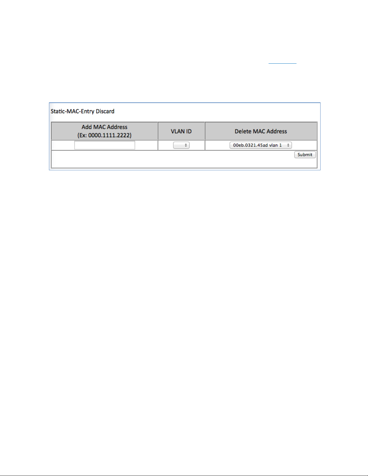
Removing a MAC address from the Static-MAC-Entry Discard Table
To remove a MAC address from the Static-MAC-Entry Discard table (see Figure 35):
1. From the drop down box underneath Delete MAC Address, select the MAC address
to be deleted.
2. Click on the Submit button.
Figure 35: Deleting a MAC – Static-MAC-Entry Table
EtherWAN Managed Switch Users Guide
92
Page 93

Port Mirroring
Port mirroring allows network traffic from one port to be copied or mirrored to another port.
This is a very useful troubleshooting feature in that all data from one port is sent to another
port which is attached to a computer or other network device that is configured to capture
packets. This enables a network administrator or technician to see the traffic that is entering
or leaving a particular port without disrupting normal network operations on the port that is
being mirrored.
To navigate to the Port Mirroring menu:
1. Click on the + next to Switching.
2. Click on Port Mirroring.
To configure port mirroring for a port or ports on the EtherWAN Managed Switch (see Figure
36):
1. Select the port or ports that traffic is to be mirrored from under the Mirror From
column.
2. Select the destination port under the Mirror To drop down box.
3. Select the type of traffic that should be mirrored from the Mirror Mode drop down
box. The available options are:
a. TX – transmit only
b. RX – Receive Only
c. TX/RX – Transmit and Receive.
4. Click on the Submit button.
EtherWAN Managed Switch Users Guide
93
Page 94

Figure 36: Port Mirroring
To disable port mirroring for a port or ports on the EtherWAN Managed Switch (see Figure
37):
1. Under the Current Settings section, the current port mirroring configuration should
be displayed.
2. Click on the Delete button.
.
Figure 37: Disabling Port Mirroring
EtherWAN Managed Switch Users Guide
94
Page 95

Link State Tracking
Link-state tracking binds the link state of multiple interfaces. Link-state tracking provides
redundancy in the network when used with server network interface card (NIC) adapter
teaming or bonding. When the server network adapters are configured in a primary or
secondary relationship known as teaming and the link is lost on the primary interface,
connectivity transparently changes to the secondary interface.
To navigate to the Link State Tracking menu:
1. Click on the + next to Switching.
2. Click on Link State Tracking.
Enable/Disable Link State Tracking
To enable Link State Tracking for a particular group on the EtherWAN Managed Switch (see
Figure 38):
1. Under Group Setting, click the check box of the Link State groups that are to be
enabled (or disabled).
2. Click on Update Setting.
Figure 38: Link State Tracking
Port Settings
To configure individual ports for a Link State group on the EtherWAN Managed Switch (see
Figure 39):
1. Under Port Setting, select the Link State Group that the port will belong to from the
Group drop down box
EtherWAN Managed Switch Users Guide
95
Page 96

2. Select if the port is upstream or downstream from the Up/Down Stream)drop down
box.
3. Click on Update Setting.
Figure 39: Link State Tracking – Port Settings
EtherWAN Managed Switch Users Guide
96
Page 97

PoE (Power over Ethernet) - System and Port Settings
This section only applies to Managed EtherWAN Switches with support for PoE.
To navigate to the PoE page:
1. Click on the + next to Switching.
2. Click on PoE.
PoE System Setting
The PoE Page provides access to PoE System Setting information and configuration. The
information provided is (See Figure 40):
1. Main Supply Voltage
2. System Temperature
3. Power Allocation – Actual wattage supplied to attached PoE device(s)
4. System Power Budget – Configurable. The default value depends on the model of
switch.
Figure 40: PoE System Setting
EtherWAN Managed Switch Users Guide
97
Page 98

PoE Port Setting
The PoE Port Setting section provides the following configurable settings and information:
1. Enable Mode – Set the PoE Enable Mode by selecting one of the following settings
in the drop-down box under PoE Mode (see Figure 41)
o Enable – Enable PoE on a specific port
o Disable – Disable PoE on a specific port
o Scheduling – Schedule time of day that PoE will be enabled per port (see
PoE Scheduling)
2. Power Limit by Classification – This setting tells the switch to negotiate with the
attached PoE device to determine the Watts that will be provided by the switch. To
change this setting, check (enable) or uncheck (disable) the check box located in the
Power Limit by Classification column. The default is checked (Enabled). This is a per
port setting (see Figure 41).
3. Fixed Power Limit – Provides a fixed Wattage to the attached PoE (PD) device.
This setting is only enabled after the Power Limit by Classification is disabled on a
port and the Submit button is clicked.
4. Power Priority – Use the Drop-Down box in the Power Priority column to set the
priority to High, Medium or Low.
5. Power Down Alarm – This setting only applies to EtherWAN Switches that have a
relay. If this box is check, losing PoE power on a port triggers the relay on the switch.
6. Status – Informational only. Provides the status of the PoE port
7. PD Class - Informational only. Provides the PoE Classification of the PoE (PD)
device attached to the PoE port
8. Current (mA) – Informational only. Shows the current draw from the attached PoE
(PD) device.
9. Consumption (W) - Informational only. Shows the power consumption of the
attached PoE (PD) device.
NOTE: For EX78000-T series switches, all eight ports (Ports 1 - 8) can now
support up to 30W PoE power. However, the total PoE power budget is still 181W.
EtherWAN Managed Switch Users Guide
98
Page 99

Figure 41: PoE Port Setting
EtherWAN Managed Switch Users Guide
99
Page 100

PoE Scheduling
PoE Scheduling allows PoE ports to have their power up time scheduled by hour of the day
and day of the week. In order for a port to follow a schedule defined here, the port must be
set to Scheduling on the PoE settings page (see PoE Port Setting)
To navigate to the PoE Scheduling page:
1. Click on the + next to Switching.
2. Click on PoE Scheduling.
Each PoE port on the switch can be schedule to power up and down automatically. To
configure a port:
1. Select the port from the drop-down list (See Figure 42)
Figure 42: Selecting a Port
2. Select the hour(s) of day for each day of the week (see Figure 43).
3. Click on the Submit button.
EtherWAN Managed Switch Users Guide
100
 Loading...