

Page 1

EtherWAN EX77900 Series Hardened Managed Switch
FastFind Links
User’s Guide
Unpacking and Installation
Computer Setup
Setting the initial IP address
1
EX77900 Series Managed Switch Users Guide
Page 2

All Rights Reserved
Dissemination or reproduction of this document, or its contents, is not authorized except
where expressly permitted. Violators are liable for damages. All rights reserved, for the
purposes of patent application or trademark registration.
Disclaimer of Liability
The information contained in this document is subject to change without notice. EtherWAN is
not liable for any errors or omissions contained herein or for resulting damage in connection
with the information provided in this manual.
Registered Trademarks
The following words and phrases are registered Trademarks of EtherWAN Systems Inc.
EtherOS™
Ethernet to the World™
All other Trademarks are property of their respective owners.
Warranty
For details on the EtherWAN warranty replacement policy, please visit our web site at:
https://kb.etherwan.com/index.php?CategoryID=13
Products Supported by this Manual:
E77900 Series Hardened Managed Switch with firmware version 2.01
Contact EtherWAN Systems
Corporate Headquarters
EtherWAN Systems Inc.
2301 E Winston Rd Anaheim
Anaheim, CA 92806
Tel: (714) 779 3800
Fax: (714) 779 3806
Email: support@etherwan.com
Page 3

Table of Contents
Preface ...................................................................................................................... 6
Audience ................................................................................................................... 6
Document Revision Level .......................................................................................... 6
Document Conventions ............................................................................................. 7
Typographic Conventions .......................................................................................... 7
Unpacking and Installation ..................................................................................... 7
Package Contents ..................................................................................................... 8
Unpacking ................................................................................................................. 8
Connecting power ...................................................................................................... 9
Required Equipment and Software (Web Interface) ................................................... 9
Computer Setup ..................................................................................................... 10
Management Methods and Protocols ...................................................................... 10
Default IP ................................................................................................................. 11
Login Process and Default Credentials .................................................................... 11
Setting the initial IP address ................................................................................. 12
Simple IP Addressing .............................................................................................. 12
CLI Command Usage ............................................................................................. 13
Navigating the CLI Hierarchy ................................................................................... 13
CLI Keyboard Shortcuts ........................................................................................... 13
System Menu (Web Interface) ............................................................................... 14
System Information .................................................................................................. 14
System Name/Password.......................................................................................... 15
System Name/Password using the CLI .................................................................... 16
In Case of Lost/Forgotten Password ........................................................................ 17
IP Address ............................................................................................................... 18
IP Address - Configuration using the CLI ................................................................. 19
Management Interface ............................................................................................. 22
Management Interface Configuration using the CLI ................................................. 24
Save Configuration Page ......................................................................................... 26
Save Configuration Page using the CLI ................................................................... 28
Firmware Upgrade ................................................................................................... 29
Firmware Update using the CLI ............................................................................... 30
Booting From Alternate (Backup) Firmware ............................................................. 31
Reboot ..................................................................................................................... 31
EX77900 Series Managed Switch Users Guide
3
Page 4

Reboot using the CLI ............................................................................................... 32
Logout ..................................................................................................................... 32
Logout from the CLI ................................................................................................. 32
Diagnostics ............................................................................................................ 32
Utilization ................................................................................................................. 32
System Log.............................................................................................................. 33
System log using CLI command .............................................................................. 33
Remote Logging ...................................................................................................... 34
Remote Logging using CLI commands ................................................................ .... 35
ARP Table ............................................................................................................... 36
ARP Table using CLI Commands ............................................................................ 37
Route Table ............................................................................................................. 37
Route Table Using CLI Commands ......................................................................... 38
Alarm Setting ........................................................................................................... 39
Port ......................................................................................................................... 41
Configuration ........................................................................................................... 41
Port Status ............................................................................................................... 43
Rate Control ............................................................................................................ 44
RMON Statistics ...................................................................................................... 45
Per Port VLAN Activities .......................................................................................... 46
Port Configuration Examples Using CLI Commands ................................ ................ 47
Switching ................................................................................................................ 50
Bridging ................................................................................................................... 50
Loopback Detect ...................................................................................................... 51
Storm Detect ............................................................................................................ 54
Static MAC Entry ..................................................................................................... 55
Port Mirroring ........................................................................................................... 58
Link State Tracking .................................................................................................. 59
Switch Configuration Examples Using CLI Commands ............................................ 61
Trunking ................................................................................................................. 67
Overview ................................................................................................................. 67
Port Trunking ........................................................................................................... 68
LACP Trunking ........................................................................................................ 69
Trunking Configuration Examples Using CLI Commands ......................................... 70
STP/Ring Page – Overview ................................ ................................................... 72
Choosing the Spanning Tree Protocols .................................................................... 72
EX77900 Series Managed Switch Users Guide
4
Page 5

STP/Ring Page - Configuring RSTP ..................................................................... 73
Global Configuration Page ....................................................................................... 73
RSTP Port Setting Page .......................................................................................... 78
RSTP Configuration Examples Using CLI Commands ............................................. 81
STP/Ring Page - Configuring MSTP ................................................................ ..... 83
Global Configuration Page ....................................................................................... 83
MSTP Properties Page ............................................................................................ 87
MSTP Instance Setting Page ................................................................................... 90
MSTP Port Setting page .......................................................................................... 92
MSTP Configuration Examples Using CLI Commands ............................................ 95
STP/RING PAGE - ALPHA RING ........................................................................... 98
Alpha Ring Setting Page .......................................................................................... 98
STP/Ring Page - Advanced Setting .................................................................... 100
Advanced Bridge Configuration ............................................................................. 101
Advanced Per Port Configuration ........................................................................... 101
Configuring Spanning Tree Advanced Settings using CLI commands.................... 103
VLAN ..................................................................................................................... 104
Port Based VLAN vs. Tagged Based VLAN ........................................................... 104
VLAN Configuration in 802.1Q Tag Based VLAN Mode ......................................... 104
802.1Q Tag Based VLAN Configuration Examples Using CLI Commands ............ 106
Add an IP to the Management VLAN ..................................................................... 108
Configuring the Port Type and the PVID setting ..................................................... 109
QoS ....................................................................................................................... 112
Global Configuration Page ..................................................................................... 113
QoS Global Configuration using the CLI Interface ................................................. 115
802.1p Priority Page .............................................................................................. 116
802.1p Priority Submenu – CLI Interface ............................................................... 117
ACL (Access Control List) .................................................................................. 119
General Overview .................................................................................................. 119
Configuring ACL .................................................................................................... 120
ACL Policy Map ..................................................................................................... 121
ACL Configuration Examples Using CLI Commands ............................................. 138
SNMP .................................................................................................................... 143
SNMP General Settings ......................................................................................... 143
Configuring SNMP v1 & v2 Community Groups ..................................................... 147
Configuring SNMP v3 Users .................................................................................. 147
EX77900 Series Managed Switch Users Guide
5
Page 6

Revision
Document Version
Date
Description
A
Version 2
5/12/2016
Firmware version 2.0.1
SNMP Configuration Examples Using CLI Commands .......................................... 152
IEEE 802.1X .......................................................................................................... 154
Configuring 802.1X from the Web Interface ........................................................... 155
LLDP ..................................................................................................................... 158
LLDP General Settings .......................................................................................... 159
LLDP Ports Settings .............................................................................................. 161
LLDP Neighbors .................................................................................................... 162
LLDP Statistics ...................................................................................................... 163
LLDP Configuration Examples Using CLI Commands ........................................... 164
Other Protocols.................................................................................................... 167
GVRP .................................................................................................................... 167
IGMP Snooping ..................................................................................................... 173
Network Time Protocol .......................................................................................... 187
GMRP .................................................................................................................... 193
DHCP Server ......................................................................................................... 199
PREFACE
Audience
This guide is designed for the person who installs, configures, deploys, and maintains the
Ethernet network. This document assumes the reader has moderate hardware, computer,
and Internet skills.
Document Revision Level
This section provides a history of the revision changes to this document.
6
EX77900 Series Managed Switch Users Guide
Page 7

Convention
Description
Bold
Indicates text on a window, other than the window title, including menus, menu options, buttons, fields, and labels.
Italic
Indicates a variable, which is a placeholder for actual text provided by the user or system. Angled brackets (< >) are
also used to indicate variables.
screen/code
Indicates text that is displayed on screen or entered by the user.
< > angled
brackets
Indicates a variable, which is a placeholder for actual text provided by the user or system. Italic font is also used to
indicate variables.
[ ] square
brackets
Indicates optional values.
| vertical bar
Indicates that you have a choice between two or more options or arguments.
Document Conventions
This guide uses the following conventions to draw your attention to certain information.
Typographic Conventions
This guide uses the following typographic conventions.
UNPACKING AND INSTALLATION
This chapter describes how to unpack and install the EtherWAN Managed Switch
The topics covered in this chapter are:
Package Contents (Page 8)
Unpacking (Page 8)
Required Equipment and Software (Page 9)
Computer Setup (Page 10)
Management Methods and Protocols (Page 10)
Default IP (Page 11)
Login Process and Default Credentials (Page 11)
Setting the initial IP address (Page 12)
EX77900 Series Managed Switch Users Guide
7
Page 8

Package Contents
When you unpack the product package, you will find the items listed below. Please inspect
the contents, and report any apparent damage or missing items immediately to your
authorized reseller.
Managed Switch
Product CD
Quick Installation Guide
External power adapter/Cable (depending on model)
Console cable (depending on model)
Unpacking
Follow these steps to unpack the EtherWAN Managed Switch and prepare it for operation:
1. Open the carton and carefully remove the contents.
2. Return all packing materials to the carton. If possible, save the carton and packing
material in case you need to ship or store the switch in the future.
3. Confirm that all items listed in the "Package Contents" section are included in the
shipment. Check each item for damage. If any item is damaged or missing, notify your
authorized EtherWAN representative.
EX77900 Series Managed Switch Users Guide
8
Page 9

Connecting power
Terminal Block
If your EX77900 comes with power cables, connect the cables into the power modules at the
back of the switch. If your switch comes with a terminal block (no cable), then connect the
switch to a suitable power supply using 12 to 24 AWG wire.
Redundant power supply is supported. However, only one power input is required to operate
the switch.
Relay Output Alarm
The switch provides relay output contacts for signaling of a user-defined power or port failure.
The relay output can be connected to an alarm signaling device. Current is 1A at 240VAC.
Normal state: 3 & 2 open, 2 & 1 closed
Alarm state: 3 & 2 closed, 2 & 1 open
Required Equipment and Software (Web Interface)
Computer with an Ethernet Interface (RJ-45)
Managing the switch requires a personal computer (PC) or notebook computer
equipped with a 10/100base-TX Ethernet interface and a physical RJ-45
connection. The preferred operating system for the computer is Microsoft Windows
7/8/8.1/10. It is possible to use Apple OSX or Linux systems as well, but, for the
sake of brevity, all web configurations in this manual will be shown using Windows
7 as the underlying operating system.
Cat 5+ Ethernet Cables
An Ethernet cable of at least Category 5 rating is required to connect your
computer to the switch. The cable can be configured as “straight-through” or
crossover.
TFTP Server Software
EX77900 Series Managed Switch Users Guide
9
Page 10

Trivial file transfer protocol (TFTP) server software is needed to update the switch
firmware and to upload/download configuration files to the switch. Users not
performing these tasks do not need TFTP software installed. Several good TFTP
servers are available for free online. The server that will be used in this manual is
TFTPD32 by Philippe Jounin.
Web Browser Software
The end user can employ any of the following web browsers during switch
configuration: Internet Explorer, Firefox, or Chrome. Internet Explorer is the
preferred browser for EtherWAN switch configuration. If there is trouble with other
browsers while attempting to program the switch, Internet Explorer should be used.
COMPUTER SETUP
The management computer may need to be reconfigured prior to connecting to the switch in
order to access the switch’s web interface through its default IP address (See Default IP).
Management Methods and Protocols
There are several methods that can be used to manage the switch. This manual
will show the details of configuring the switch using a web browser. Each section
will be followed by the CLI (Command Line Interface) commands needed to
achieve the same results as described in that section.
The methods available to manage the EtherWAN Managed Switch include:
SSH - Secure Shell CLI that is accessible over TCP/IP networks which and
is generally regarded as the most secure method of remotely accessing a
device.
Telnet - is like SSH in that it allows a CLI to be established across a
TCP/IP network, but it does not encrypt the data stream. This type of
connection requires a terminal, or a computer running a terminal emulation
application (such as HyperTerminal or Putty).
HTTP (Hypertext Transfer Protocol) is the most popular switch
management protocol involving the use of a web browser.
EX77900 Series Managed Switch Users Guide
10
Page 11
HTTPS (Hypertext Transfer Protocol) HTTP with encryption.
RS-232 – The EtherWAN Managed Switch is equipped with a RS-232
Default IP
The switch’s default IP address is 192.168.1.10. The management computer must
be set up so that it is on the same network as the switch. For example, the IP
address of the management computer can be set to 192.168.1.100 with a subnet
mask of 255.255.255.0.
serial port that can be used to access the switch CLI. The Serial port is DCE DB-9F. A straight through serial cable is used to connect to a typical
computer serial port (Also requires terminal emulation application).
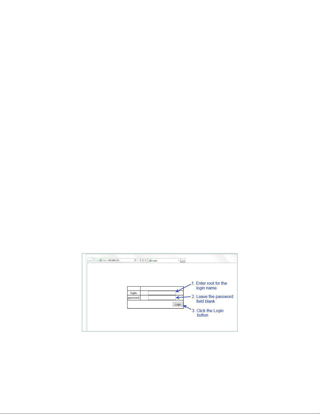
Login Process and Default Credentials
Once a compatible IP address has been assigned to the management computer,
the user is ready to log in to the switch. To log in, type the URL http://192.168.1.10/
into the address field of the browser and hit return. (See Figure 1)
The Default Login is root (case sensitive)
There is no password by default
Enter the login name and click the Login button
Figure 1: Login screen
EX77900 Series Managed Switch Users Guide
11
Page 12

SETTING THE INITIAL IP ADDRESS
Once logged in the user can now configure the switch per the network requirements. The
two major addressing options are:
Simple IP addressing
Multiple VLAN addressing (See Add an IP to the Management VLAN on page 108).
Simple IP Addressing
A new IP address can now be assigned to the switch. From the System Information screen,
go to the left hand navigation menu.
1. Click on the + next to System
2. Click on IP address
3. Enter the desired IP address and subnet mask in the IP Address/Subnet Mask
fields associated with VLAN 1
4. Click the Apply & Save button (See Figure 2)
Note: You will need to log in to the switch again after changing the IP address.
Figure 2: Assigning an IP address
EX77900 Series Managed Switch Users Guide
12
Page 13

CLI COMMAND USAGE
This chapter describes accessing the EtherWAN Managed Switch by using Telnet, SSH, or
serial ports to configure the switch, navigating the Command Line Interface (CLI), typing
keyboard shortcuts, and moving between the levels. This chapter assumes the user has a
working understanding of Telnet, SSH and Terminal emulation applications.
Note: For a serial port connection use a standard DB-9F to DB-9M Modem Cable. The
default Serial port parameters are Baud rate: 115,200bps, Data bits: 8, Parity: none, Stop bit:
1, Flow control: none.
Navigating the CLI Hierarchy
The CLI is organized into a hierarchy of command modes. The basic modes are User exec
mode, Privileged exec mode, and Global configuration mode. There are also other modes,
specific to certain configurations. Each mode has its own group of commands for a specific
purpose. Below are the CLI commands needed to enter a specific mode.
switch_a> ← User exec mode
switch_a>enable
switch_a# ← Privileged exec mode
switch_a#configure terminal
switch_a(config) ← Global configuration mode
switch_a(config) spanning-tree mst configuration
switch_a(config-mst)# ← MSTP configuration mode
switch_a(config)# interface fe1
switch_a(config-if)# ← Interface configuration mode
switch_a(config)#vlan database
switch_a(config-vlan)# ← VLAN database configuration mode
CLI Keyboard Shortcuts
Ctrl + a: place cursor at the beginning of a line
Ctrl + b: backspace one character
Ctrl + d: delete one character
Ctrl + e: place cursor at the end of the line
EX77900 Series Managed Switch Users Guide
13
Page 14

Ctrl + f: move cursor forward one character
Ctrl + k: delete from the current position to the end of the line
Ctrl + l: redraw the command line
Ctrl + n: display the next line in the history
Ctrl + p: display the previous line in the history
Ctrl + u: delete entire line and place cursor at start of prompt
Ctrl + w: delete one word back
SYSTEM MENU (WEB INTERFACE)
System Information
The System information link on the Left menu of the Web Configuration page takes you to a
page that shows the following (see Figure 3):
System Name
o The System name is typically used by network administrators. If SNMP is
enabled on the switch, the system name can be found using MIB II (RFC1213)
in the sysName property.
Firmware Version
o This displays the primary firmware version and date of last update
System Time
o System time can be changed using NTP
MAC Address
o The hardware (MAC) address of the Management interface
Default Gateway
o The IP address of your networks Gateway (Typically a Router on your
network)
DNS Server
o The Dynamic Name Server (DNS) for your network
14
EX77900 Series Managed Switch Users Guide
Page 15

Alternate Firmware
o This shows the backup firmware version mirrored on the switch. If the switch
becomes unbootable from the primary firmware image, it will boot to this
version on the next boot.
VLAN ID
o One or more listings depending on the number of VLANs defined on the
switch
o Lists VLAN ID, IP address, and subnet mask of the VLAN Interface(s)
Figure 3: System Information
System Name/Password
The System name is typically used by network administrators to make it easier to document
a networks infrastructure and locate equipment on large networks. If SNMP is enabled on
the switch, the system name can be found using MIB II (RFC1213) in the sysName property.
To change the system name:
1. Click on the + next to System.
2. Click on System Name/Password (see Figure 4).
15
EX77900 Series Managed Switch Users Guide
Page 16

3. Use your mouse to place the cursor in the System Name text box.
4. Replace the existing name with the name you want to assign to the switch.
5. Click on the Update Setting button.
By default there is no password assigned to the switch. To add or change a password:
1. Click on the + next to System.
2. Click on System Name/Password (see Figure 4).
3. Use your mouse to place the cursor in the Password text box.
4. Enter the new password.
5. Retype the password in the Retype Password text box.
6. Click on the Update Setting button below the Retype Password text box.
Figure 4: System Name/Password
System Name/Password using the CLI
For more information on CLI command usage see CLI Command Usage.
System Name
To set the system name on a switch, use the following CLI commands:
EX77900 Series Managed Switch Users Guide
16
Page 17

CLI Command Mode: Global Configuration Mode
CLI Command Syntax:
hostname <name>
no hostname
Usage Example 1: Setting a Hostname to “switch_a”
switch_a(config)#hostname switch_a
Password
To enable a password on a switch, use the following CLI commands:
CLI Command Mode: Global Configuration Mode
CLI Command Syntax:
enable password <password>
Usage Example: Setting switch password to “mypassword”
switch_a(config)#enable password mypassword
In Case of Lost/Forgotten Password
1. If the switch cannot be accessed because the password is not known, then the
switch must be reset. This must be done by connecting to the switch through the RS232 serial port.
2. Connect to the switch’s RS-232 port with a terminal emulator.
3. Power cycle the switch (turn the power off and then on).
4. While the switch is rebooting, hold down Ctrl + C. This will cause the switch to enter
CFE (Common Firmware Environment) mode. The prompt should look like this:
CFE_1.5>
5. Enter the command reset_default. This will reset the switch to its factory default
settings.
NOTE: Restoring the switch to factory defaults will reset all data and settings.
EX77900 Series Managed Switch Users Guide
17
Page 18

IP Address
To navigate to the IP Address page:
1. Click on the + next to System
2. Click on IP Address (see Figure 5)
There are 4 settings on this page:
Static IP (see Simple IP Addressing)
DHCP Client
Use this to enable or disable DHCP on a VLAN.
To enable the DHCP Client:
1. Use the drop down box to enable the DHCP client on a particular VLAN
2. Click the Submit Button
Default Gateway
If DHCP is enabled, the gateway setting is controlled by the DHCP server. The
setting will be grayed out and the gateway supplied by the DHCP server will be
displayed. The default gateway setting can be used when using a Static IP address.
To enable the default gateway:
1. Use the dropdown box to enable the default gateway.
2. Type in the default gateway in the Default Gateway text box.
3. Click on the Apply & Save button.
DNS Server
If DHCP is enabled, the DNS Server setting is controlled by the DHCP server. The
setting will be grayed out and the DNS Server supplied by the DHCP server will be
displayed. The DNS Server setting can be used when using a Static IP address. To
enable the DNS Server:
1. Use the dropdown box to enable the DNS Server.
2. Type in the default gateway in the Default Gateway text box.
3. Click on the Submit button.
Note: After making changes to settings in the IP address section, the
configuration needs to be saved using the System/Save configuration page
(See Save Configuration)
18
EX77900 Series Managed Switch Users Guide
Page 19
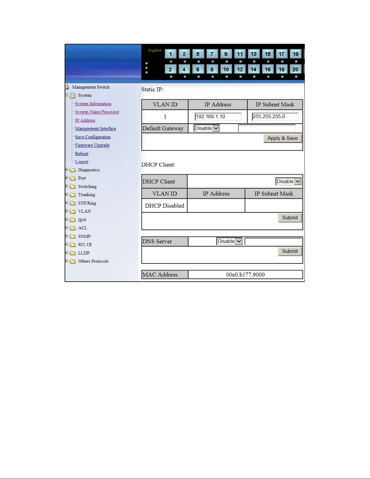
Figure 5: IP Address
IP Address - Configuration using the CLI
IP Address
To set the IP address, use the following CLI commands:
CLI Command Mode: Global Configuration Mode
CLI Command Syntax:
ip address <A.B.C.D/M> (IP Address/Mask e.g. 10.0.0.1/8)
no ip address
EX77900 Series Managed Switch Users Guide
19
Page 20

Note: The Subnet Mask is defined as a Network Prefix instead of the common dotted
decimal (ex. 255.255.255.0).
The most commonly used Network Prefixes are:
/8 – Known as Class A. Also known in dotted decimal as 255.0.0.0
/16– Known as Class B. Also known in dotted decimal as 255.255.0.0
/24– Known as Class C. Also known in dotted decimal as 255.255.255.0
Usage Example 1: Assigning an IP address of 192.168.1.1 with subnet mask of
255.255.255.0
switch_a(config)#ip address 192.168.1.1/24
switch_a(config)#q
switch_a#write memory
Building configuration.....
[OK]
Usage Example 2: Removing an IP address
switch_a(config)#no ip address
switch_a(config)#q
switch_a#write memory
Building configuration.....
[OK]
Default Gateway
To set the Default Gateway, use the following CLI commands:
CLI Command Mode: Global Configuration Mode
CLI Command Syntax:
ip default-gateway <A.B.C.D>
no ip default gateway
Usage Example 1: Setting the default gateway to 192.168.1.254
switch_a(config)#ip default-gateway 192.168.1.254
switch_a(config)#q
switch_a#write memory
Building configuration.....
[OK]
EX77900 Series Managed Switch Users Guide
20
Page 21

Usage Example 2: Removing the Gateway
switch_a(config)#no ip default-gateway
switch_a(config)#q
switch_a#write memory
Building configuration.....
[OK]
Domain Name Server (DNS)
To set the DNS, use the following CLI commands:
CLI Command Mode: Global Configuration Mode
CLI Command Syntax:
ip dns <A.B.C.D>
no ip dns
Usage Example: Set Domain name server to 192.168.1.253
switch_a(config)#ip dns 192.168.1.253
switch_a(config)#q
switch_a#write memory
Building configuration.....
[OK]
Usage Example 2: Remove a DNS IP Address
switch_a(config)#no ip dns
switch_a(config)#q
switch_a#write memory
Building configuration.....
[OK]
Enable/Disable DHCP Client on a VLAN
To enable the DHCP client on a VLAN, use the following CLI commands:
CLI Command Mode: Interface Configuration Mode
CLI Command Syntax:
get ip dhcp enable
no get ip dhcp enable
Usage Example – Enable DHCP Client on VLAN2:
switch_a(config)#interface vlan1.2
switch_a(config-if)#get ip dhcp enable
switch_a(config-if)#q
EX77900 Series Managed Switch Users Guide
21
Page 22

switch_a(config)#q
switch_a#write memory
Building configuration.....
[OK]
Enable/Disable Static IP on a VLAN
To set the IP address, use the following CLI commands:
CLI Command Mode: Interface Configuration Mode
CLI Command Syntax:
ip address <A.B.C.D>
no ip address <A.B.C.D>
Usage Example 1 – Enable Static IP of 192.168.1.11 with subnet mask 255.255.255.0 on
VLAN2:
switch_a(config)#interface vlan1.2
switch_a(config-if)#ip address 192.168.1.11/24
switch_a(config-if)#q
switch_a(config)#q
switch_a#write memory
Building configuration.....
[OK]
Usage Example 2 – Disable Static IP on VLAN2:
switch_a(config)#interface vlan1.2
switch_a(config-if)#no ip address
switch_a(config-if)#q
switch_a(config)#q
switch_a#write memory
Building configuration.....
[OK]
Management Interface
To navigate to the Management Interface page:
1. Click on the + next to System
2. Click on Management Interface
The Management Interface configuration page has three settings that allow the user to
configure the methods available to manage the EtherWAN Managed Switch.
EX77900 Series Managed Switch Users Guide
22
Page 23

HTTPS
HTTPS (Hypertext Transfer Protocol Secure) allows the user to determine what
method, if any, is used to configure the EtherWAN Managed Switch. The default is
unencrypted HTTP (see Figure 6).
To disable the Web interface:
1. Uncheck Http and Https.
2. Click on the Update setting button.
Warning! Once the Submit button is pressed, the Web console will no longer
function. As a safety precaution, the configuration is not saved by default. Rebooting
the EtherWAN Managed Switch will restore the Web Console. To save the
configuration, connect using the new IP address.
To enable the Web Interface:
1. Check HTTP, HTTPS or both
2. Click on the Update Setting button.
3. Save the Configuration (see Save Configuration)
Telnet.
Telnet is a network protocol that allows a remote computer to log into the EtherWAN
Managed Switch to access its CLI (Command Line Interface). The CLI can be access
using Telnet, SSH and the serial port on the EtherWAN Managed Switch. The secure
method of accessing the CLI over a network is SSH.
To enable or disable Telnet:
1. Click the Enable or Disable radio button in the Telnet section on the
Management Interface page (see Figure 6 below)
2. Click on the Update Setting button
3. Save the Configuration (see Save Configuration)
SSH (Secure Shell)
Secure Shell or SSH is a network protocol that allows data to be exchanged using a
secure channel between two networked devices such as a computer and the
EtherWAN Managed Switch. SSH is disabled by default on the V1.94.2 EtherWAN
Managed Switch.
To enable or disable SSH:
1. Click the Enable or Disable radio button in the SSH section on the
Management Interface page (see Figure 6)
EX77900 Series Managed Switch Users Guide
23
Page 24

2. Click on the Update Setting button
3. Save the Configuration (see Save Configuration)
Figure 6: Management Interface
Management Interface Configuration using the CLI
Enabling/Disabling Telnet
To enable or disable telnet, use the following CLI commands:
CLI Command Mode: Global Configuration Mode
CLI Command Syntax:
ip telnet
no ip telnet
Usage Example: Enabling Telnet:
switch_a(config)#ip telnet
EX77900 Series Managed Switch Users Guide
24
Page 25

switch_a(config)#q
switch_a#write memory
Building configuration.....
[OK]
Note: If using Telnet to run the CLI Commands that disable telnet you will lose your
connection. To Disable Telnet using the CLI, use SSH or the RS-232 Console port
on the switch.
Enabling/Disabling SSH
To enable or disable SSH, use the following CLI commands:
CLI Command Mode: Global Configuration Mode
CLI Command Syntax:
ip ssh
no ip ssh
Note: If using SSH to run the CLI Commands that disable SSH you will lose your
connection. To Disable SSH using the CLI, use Telnet or the RS-232 Console port
on the switch.
Enabling/Disabling HTTP and/or HTTPS
To enable or disable HTTP or HTTPS, use the following CLI commands:
CLI Command Mode: Global Configuration Mode
CLI Command Syntax:
ip http server
ip http secure-server
no ip http server
no ip http secure-server
25
EX77900 Series Managed Switch Users Guide
Page 26

Save Configuration Page
To navigate to the Save Configuration page:
1. Click on the + next to System
2. Click on Save Configuration
The Save Configuration page contains the following configuration functions (see Figure 7):
Save Configuration
To save the currently running configuration to the flash memory on the EtherWAN
Managed Switch:
1. Click the Save Configuration button
2. If the save is successful you will see the message:
Building configuration….. [OK]
Load Configuration
This function is used to load a previously saved configuration. Backing up and
loading a configuration is usually achieved using a TFTP server.
To load a configuration:
1. Enter the IP address of your TFTP server in the TFTP Server text box
2. Enter the name of the configuration file in the FILE text box
3. Click on the Backup button
4. If the file is successfully loaded the following message will be shown:
Success! System reboot is required!
Backup Configuration
This function is used to back up the current switch configuration. Backing up the
configuration is usually achieved using a TFTP server such as TFTPD32.
To back up a configuration:
1. Enter the IP address of your TFTP server in the TFTP Server text box
2. Enter the name of the configuration file in the FILE text box
3. Click on the Backup button
4. If the backup is successful the following message will be shown:
tftp <filename> to ip <ip address> success!!
26
EX77900 Series Managed Switch Users Guide
Page 27

Restore Default
To restore the switch to factory defaults:
1. Click on the Restore Default button.
2. The switch will ask for confirmation, then reboot.
NOTE: Restoring the switch to factory defaults will reset all data, including user
accounts and passwords.
Auto Save
The Auto Save function is used to set the switch to automatically save the
configuration to flash. If the saved configuration is the same as the running
configuration then a save is not made. The Auto Save interval is used to determine
how often the running configuration is checked for changes.
To set the Auto Save function:
1. Click the dropdown box next to Auto Save.
2. Set the Auto Save interval (5~65535 sec)
Note: If a Firewall is running on the PC that is running the TFTP server it may need
to be temporarily disabled.
Figure 7: Save Configuration Page
EX77900 Series Managed Switch Users Guide
27
Page 28

Save Configuration Page using the CLI
Saving a Configuration
To save a running configuration, use the following CLI commands:
CLI Command Mode: Global Configuration Mode
CLI Command Syntax:
write memory
Usage Example: Saving a Configuration
switch_a#write memory
Building configuration.....
[OK]
Restore Default Settings
To restore the switch to its default settings, use the following CLI commands:
CLI Command Mode: Global Configuration Mode
CLI Command Syntax:
restore default
Usage Example: Restoring a Configuration
switch_a#restore default
Load Configuration from a TFTP Server
To Load a Configuration from a TFTP server, use the following CLI commands:
CLI Command Mode: Privileged Exec Mode
CLI Command Syntax:
install config-file <tftpserver_ipaddress> <filename>
Usage Example: Loading a Configuration from TFTP server on 192.168.1.100, where
configuration file is file_name.tgz
switch_a#install config-file 192.168.1.100 file_name.tgz
EX77900 Series Managed Switch Users Guide
28
Page 29

Save Configuration to a TFTP Server
To Save a Configuration to a TFTP server, use the following CLI commands:
CLI Command Mode: Privileged Exec Mode
CLI Command Syntax:
write config-file <tftpserver_ipaddress> <filename>
Usage Example: Saving a Configuration to TFTP server on 192.168.1.100, where
configuration file is named flash.tgz
switch_a#write config-file 192.168.1.100 flash.tgz
Auto Save Configuration
To set the Auto Save Configuration, use the following CLI commands:
CLI Command Mode: Configure Mode
CLI Command Syntax:
service auto-config enable
no service auto-config enable
service auto-config interval <number>
Usage Example 1: Enabling Auto Save with interval of 10 seconds
switch_a(config)#service auto-config enable
switch_a(config)#service auto-config interval 10
Usage Example 2: Disabling Auto Save
switch_a(config)#no service auto-config enable
Firmware Upgrade
To navigate to the Firmware Upgrade page:
1. Click on the + next to System
2. Click on Firmware Upgrade
To upgrade the firmware, a TFTP server is required. The firmware file for the switch is in
a .TGZ or .IMG format. This is a compressed file; however, it should not be decompressed
before updating the switch.
To update the firmware on the EtherWAN Managed Switch (see Figure 8):
EX77900 Series Managed Switch Users Guide
29
Page 30

1. Copy the firmware file to the correct directory for your TFTP server. The correct
directory depends on your TFTP server settings
2. Enter the filename of the firmware in the Filename text box.
3. Enter the IP Address of your TFTP server in the TFTP Server IP text box.
4. Click on the Upgrade button.
5. During the firmware upgrade you will see the following messages. Do not reboot or
unplug the switch until the final message is received.
a. Downloading now, please wait...
b. tftp <filename>.img from ip <ip address> success!!
Install now. This may take several minutes, please wait...
c. Firmware upgrade success!
Note: If a Firewall is running on the PC that is running the TFTP server it may need to
be temporarily disabled.
Figure 8: Firmware Upgrade Page
Firmware Update using the CLI
To display the current primary and alternate firmware versions:
CLI Command Mode: Privileged Exec Mode
CLI Command Syntax:
show firmware
To update firmware from a TFTP server:
CLI Command Mode: Privileged Exec Mode
EX77900 Series Managed Switch Users Guide
30
Page 31

CLI Command Syntax:
install image <tftpserver_ipaddress> <filename>
Usage Example: Loading new firmware from TFTP server on 192.168.1.100, where filename
is file_name.tgz
switch_a#install image 192.168.1.100 flash.tgz
Note: Depending on the firmware being loaded, the extension may not be .tgz. The
Switch does not use the extension to validate firmware.
Booting From Alternate (Backup) Firmware
Under certain circumstances, such as when there is a loss of power during an upgrade, the
firmware build on the switch can become unstable. To prevent the switch from becoming
unbootable in this situation, there are two firmware images stored on the switch: primary and
backup. If the primary firmware image becomes unstable, the switch will detect it
automatically and boot from the backup image on the next boot.
You can also manually boot from the backup firmware image. To do so, follow these steps:
1. Connect to the switch’s RS-232 port with a terminal emulator.
2. Power cycle the switch (turn the power off and then on).
3. While the switch is rebooting, hold down Ctrl + C. This will cause the switch to enter
CFE mode. The prompt should look like this:
CFE_1.5>
4. Use the command boot_image0 and boot_image1 to manually boot from the
primary and alternate firmware images respectively. Future boots will be from the
image selected with this command.
Reboot
To navigate to the Reboot page:
1. Click on the + next to System
2. Click on Reboot
To reboot the EtherWAN Managed Switch:
1. Click on the Reboot button.
2. Click OK on the popup message.
EX77900 Series Managed Switch Users Guide
31
Page 32

Reboot using the CLI
CLI Command Mode: Privileged Exec Mode
CLI Command Syntax:
reload
Logout
To logout of the Web Configuration Console:
1. Click on the + next to System
2. Click on Logout
Logout from the CLI
CLI Command Mode: Exec mode or Privileged Exec Mode
CLI Command Syntax:
logout
DIAGNOSTICS
Utilization
To navigate to the Utilization page:
1. Click on the + next to Diagnostics.
2. Click on Utilization.
The Utilization page shows (see Figure 9):
CPU Utilization – Current and Max Utilization
Memory Utilization – Total, Used and Free Memory
EX77900 Series Managed Switch Users Guide
32
Page 33

Figure 9: Utilization Page
System Log
To navigate to the System Log page:
1. Click on the + next to Diagnostics.
2. Click on System Log.
The System Log shows the data and time of port links going up or down (see Figure 10)
Figure 10: System Log
System log using CLI command
CLI Command Mode: Exec Mode or Privileged Exec Mode
CLI Command Syntax:
show system-log
EX77900 Series Managed Switch Users Guide
33
Page 34

Remote Logging
To navigate to the Remote Logging page:
1. Click on the + next to Diagnostics.
2. Click on Remote Logging.
Remote Logging to a Syslog server allows administrators to log important system and
debugging information. The Remote Logging configuration page allows reporting to a Syslog
server to be enabled or disabled as well as management of a list of Syslog servers to report
to (see Figure 11).
To configure the Remote Logging on the EtherWAN Managed Switch:
1. Click on the Enable or Disable radio button under Remote Logging.
2. Click on the Update Setting button.
To add a Syslog server:
1. Enter the IP Address of the Syslog Server in the Syslog Server IP text box.
2. Click on the Add Syslog Server button.
To delete a Syslog server from the list of servers currently on the switch:
1. Select the Syslog server from the Drop down box
2. Click on the Delete Syslog Server button
EX77900 Series Managed Switch Users Guide
34
Page 35

Figure 11: Remote Logging Page
Remote Logging using CLI commands
Enable/Disable Remote Logging
CLI Command Mode: Global Config Mode
CLI Command Syntax:
remote-log enable
no remote-log enable
Usage Example 1: Enable Remote Logging
switch_a(config)#remote-log enable
Add/Delete a Remote Logging Host
CLI Command Mode: Global Config Mode
CLI Command Syntax:
remote-log add <ip_address>
remote-log del <ip_address>
remote-log del all
Usage Example 1: Add a Remote Logging Host at 192.168.1.100
switch_a(config)#remote-log add 192.168.1.100
EX77900 Series Managed Switch Users Guide
35
Page 36

Usage Example 2: Delete a Remote Logging Host at 192.168.1.100
switch_a(config)#remote-log del 192.168.1.100
ARP Table
To navigate to the ARP Table page:
1. Click on the + next to Diagnostics.
2. Click on ARP Table.
The ARP Table page shows ARP (Address Resolution Protocol) entries that are stored in
the Switches ARP Table. This is useful for troubleshooting purposes. The information shown
is:
IP Address of the listed device
Hardware Type – For Ethernet devices this will always be 1.
Flags
o 2 = Device responded to ARP Request
o 0 = No response to ARP Request
Hardware Address – MAC Address of the listed device
VLAN – The VLAN that the listed device is on
EX77900 Series Managed Switch Users Guide
36
Page 37

Figure 12: ARP Table
ARP Table using CLI Commands
CLI Command Mode: Global Configuration Mode
CLI Command Syntax:
show arp-table
Route Table
To navigate to the Route Table page:
1. Click on the + next to Diagnostics.
2. Click on Route Table.
The Route Table lists the routes to network destinations and metrics (distances) that are
associated with those routes. The Route Table contains information about the topology of
the network around it.
EX77900 Series Managed Switch Users Guide
37
Page 38

Figure 13: Route Table
Route Table Using CLI Commands
CLI Command Mode: Privileged Exec Mode
CLI Command Syntax:
show route-table
Usage Example:
switch_a#show route-table
Destination Gateway Genmask Flags Metric Ref Use VLAN
10.58.7.0 0.0.0.0 255.255.255.0 U 0 0 0 1
EX77900 Series Managed Switch Users Guide
38
Page 39
Alarm Setting
This setting applies only to Switch models that have a hardware relay.
To navigate to the Alarm Setting page:
1. Click on the + next to Diagnostics.
2. Click on Alarm Setting.
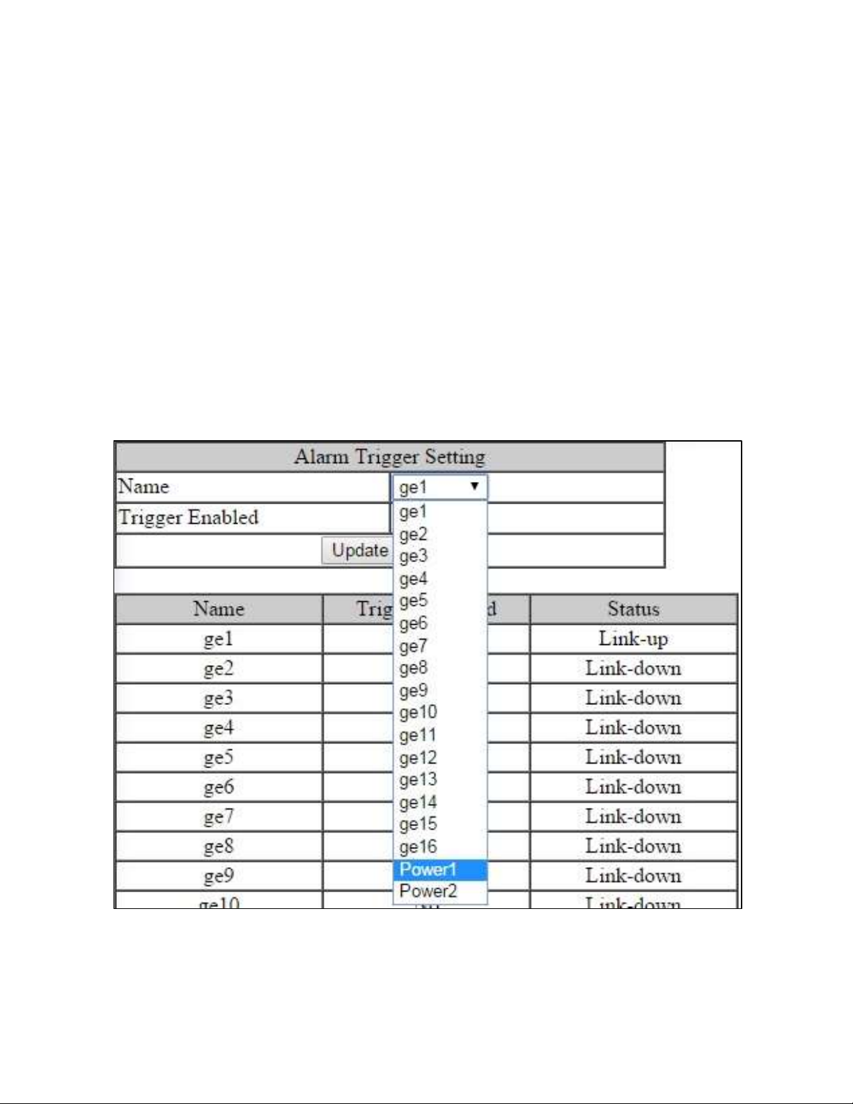
The Alarm Setting page allows users to define Ethernet port Link-down and Power failure
alarms for triggering an alarm using the relay on the switch.
To configure an Ethernet port or Power input:
1. Select an Ethernet port or Power input from the dropdown box (see Figure 14).
Figure 14: Alarm Trigger
39
EX77900 Series Managed Switch Users Guide
Page 40

3. Select YES or NO from the dropdown box next to Trigger Enabled (see Figure 15).
4. Click Update Setting to save any changes made.
Figure 15: Trigger Enable
Dying Gasp
The dying gasp function allows the switch to send a message to a syslog or SNMP server if
power to the switch is lost.
To set the notifications for Dying Gasp:
1. Select the Primary and Secondary notifications, either SNMP Trap or Syslog.
2. Click the Update Setting button.
Figure 16: Dying Gasp
Dying Grasp Using CLI Commands
Show current primary and secondary Dying Gasp settings
CLI Command Mode: Privileged Exec Mode
CLI Command Syntax:
show dying-gasp status
Set primary and secondary Dying Gasp messages
CLI Command Mode: Global Config Mode
CLI Command Syntax:
dying-gasp primary <delivery_method> secondary <delivery_method>
EX77900 Series Managed Switch Users Guide
40
Page 41

PORT
Configuration
To navigate to the Configuration page:
1. Click on the + next to Port.
2. Click on Configuration.
Port configuration contains features as flow control, port speed, and duplex settings. These
settings can be very useful when the switch is connected to a latency-critical device such as
a VOIP phone, IP camera, or video multiplexor. The ability to alter port settings can make
the difference between a poorly responding device and one that functions without loss of
data or clarity.
.The Configuration page shows (see Figure 17):
Port Number – fe(n) for 100mb ports and ge(n) for Gigabit ports
Link Status – Operational State of the Port’s Link (Read-Only)
Port Description – User-supplied Port Description
Admin Setting – Administratively Enable or Disable the Port.
Speed – Speed and Duplex Settings for Port.
Flow Control – State of Flow Control for the Port.
To provide a description to a port on the EtherWAN Managed Switch:
1. Click in the Description text box for the appropriate port.
2. Type in the description of the port.
3. Click on the Submit button.
To enable or disable a port on the EtherWAN Managed Switch:
1. Click on the drop-down box under Admin Setting and select either Link Up or Link
Down.
2. Click on the Submit button.
41
EX77900 Series Managed Switch Users Guide
Page 42

To set the Port Speed and/or Port Duplex Settings on the EtherWAN Managed Switch:
1. Click on the drop-down box under Speed and select the desired port speed / duplex
settings for that port. Please note, not all port types will have the same options. For
example, 100Mb fiber ports will typically be limited to a single option of 100M/FD
(100Mbps and Full Duplex) while running 1Gb UTP ports will have six options for
speed/duplex.
2. Click on the Submit button.
To enable or disable a port’s Flow Control settings on the EtherWAN Managed Switch:
1. Click on the drop-down box under Flow Control and select either Enable or Disable.
2. Click on the Submit button.
Figure 17: Port Configuration
42
EX77900 Series Managed Switch Users Guide
Page 43

Port Status
To navigate to the Port Status page:
1. Click on the + next to Port.
2. Click on Port Status.
This page is a read-only page that lists the settings described in the previous section. It is
useful if all the user intends to do is read the values of the port settings, not modify the port
settings. .The Port Status page shows (see Figure 18):
Port Number – fe(n) for 100mb ports and ge(n) for Gigabit ports
Link Status – Operational State of the Port’s Link.
Port Description – User-supplied Port Description
Admin Setting – Administratively State of the Port.
Speed – Speed and Duplex Settings for Port.
Flow Control – State of Flow Control for the Port.
Figure 18: Port Status
EX77900 Series Managed Switch Users Guide
43
Page 44
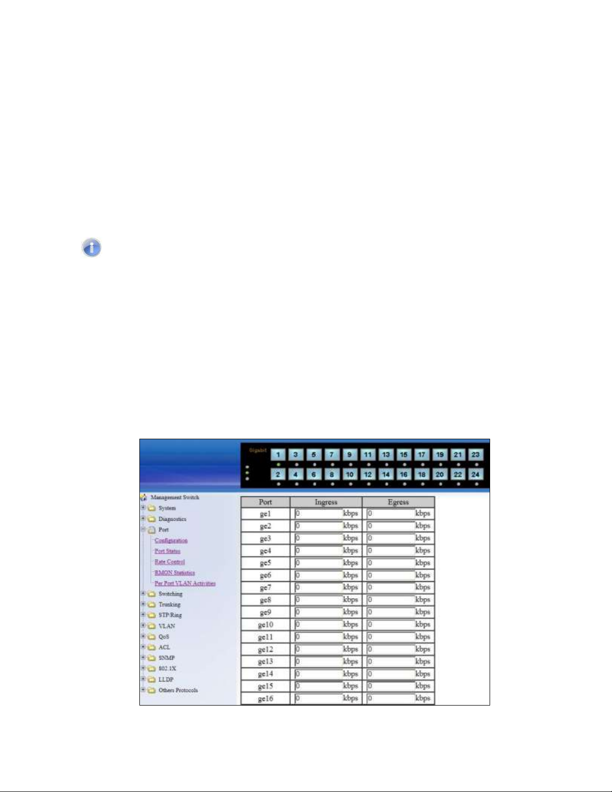
Rate Control
To navigate to the Rate Control page:
1. Click on the + next to Port.
2. Click on Rate Control.
The Rate Control page allows the user to set the maximum throughput on a port or ports on
both packets entering the port (from the connected device) or packets leaving the port.
The Ingress text box controls the rate of data traveling into the port while the Egress text
box controls the rate of data leaving the port.
Note: Entries will be rounded down to the nearest acceptable rate value. If the value
entered is below the lowest acceptable value then the lowest acceptable value will be
used.
The Rate Control page is shown below (see Figure 19):
To provide either an ingress or egress rate control for a port on the EtherWAN Managed
Switch:
1. Click in the Ingress or Egress Text Box for the appropriate port.
2. Type in the ingress/egress rate for the port according to the values listed above.
3. Click on the Update Setting button.
EX77900 Series Managed Switch Users Guide
44
Page 45

Figure 19: Rate Control
RMON Statistics
To navigate to the RMON Statistics page:
1. Click on the + next to Port.
2. Click on RMON Statistics.
RMON Statistics gives a detailed listing of the types and quantity of packets that a particular
port has seen since the last reboot of the switch (see Figure 20).
To view the RMON statistics for a particular port on the EtherWAN Managed Switch:
1. Click on the link to the port at the top of the RMON Statistics page.
To clear the RMON statistics for a particular port on the EtherWAN Managed Switch:
1. Click on the link to the port at the top of the RMON Statistics page.
2. Click on the Clear button at the bottom of the page.
3. The statistics for the port will update every ten seconds.
Pay particular attention to the values for CRC/Alignment errors and collisions. Nonzero
values for these fields can indicate that a port speed or duplex mismatch exists on the port.
EX77900 Series Managed Switch Users Guide
45
Page 46

Figure 20: RMON Page
Per Port VLAN Activities
To navigate to the Per Port VLAN Activities page:
1. Click on the + next to Port.
2. Click on Per Port VLAN Activities.
This is a read-only page that will allow the user to see what devices are connected to a
particular port and the vlan associated with that device and port.
To clear the MAC addresses for a particular port on the EtherWAN Managed Switch (see
Figure 21):
1. Click on the link to the port at the top of the Per Port VLAN Activities page.
2. Click on the Clear MAC button at the bottom of the page.
3. The statistics for the port will update every ten seconds.
46
EX77900 Series Managed Switch Users Guide
Page 47

Figure 21: Port VLAN Activities
Port Configuration Examples Using CLI Commands
Setting the Port Description
To provide a description of a port use the CLI commands below:
CLI Command Mode: Interface Configuration Mode
CLI Command Syntax: description <description text>
Usage Example:
switch_a(config-if)#description A_Port_Description
EX77900 Series Managed Switch Users Guide
47
Page 48

Enable or Disable a Port
To administratively enable or disable a port use the CLI commands below:
CLI Command Mode: Interface Configuration Mode
CLI Command Syntax:
shutdown
no shutdown
Setting the Port Speed
To set the port speed for a port use the CLI commands below:
CLI Command Mode: Interface Configuration Mode
CLI Command Syntax: bandwidth <1-10000000000 bits> (usable units : k, m, g)
Usage Example:
switch_a(config-if)#bandwidth 100m
Setting Port Duplex
To set the duplex for a port use the CLI commands below:
CLI Command Mode: Interface Configuration Mode
CLI Command Syntax: duplex <full | half | auto>
Usage Example:
switch_a(config-if)#duplex full
Enable or Disable Port Flow Control
To enable or disable flow control for a port use the CLI commands below:
CLI Command Mode: Interface Configuration Mode
CLI Command Syntax: flowcontrol on
Usage Example:
switch_a(config-if)#flowcontrol on
48
EX77900 Series Managed Switch Users Guide
Page 49

Display Port Status
To display the port status for a port use the CLI commands below:
CLI Command Mode: Privileged Exec Mode
CLI Command Syntax: show interface <ifname>
Usage Example:
switch_a#show interface fe1
Setting a Ports Rate Control
To set a ports rate control use the CLI commands below:
CLI Command Mode: Interface Configuration Mode
CLI Command Syntax: rate-control <ingress | egress> value <value in kbps>
Usage Example:
switch_a(config-if)#rate-control ingress value 100000
Display a Ports RMON Statistics
To display a ports RMON statistics use the CLI commands below:
CLI Command Mode: Privileged Exec Mode
CLI Command Syntax: show interface statistics <interface name>
Usage Example:
switch_a#show interface statistics fe1
Display a Ports VLAN Activities
To display a port’s VLAN activities use the CLI commands below:
CLI Command Mode: Privileged Exec Mode
CLI Command Syntax: show bridge interface <interface name>
Usage Example:
switch_a#show bridge interface fe1
49
EX77900 Series Managed Switch Users Guide
Page 50

SWITCHING
Bridging
To navigate to the Bridging page:
1. Click on the + next to Switching.
2. Click on Bridging.
Ageing Time
The Ageing Time value is a global value and represents the time that a networked device’s
MAC address will live in the switch’s memory before being removed. The default value is
300 seconds (5 minutes) (see Figure 22).
To update the Ageing Time value:
1. Click in the Error Disable Recovery text box at the top of the Port Security DynamicMAC page.
2. Type in the desired value. Values can be from 0 to 65535 seconds. A value of 0
indicates that the port is not to return to normal operating condition until an
administrator resets the port or the switch is restarted.
3. Click on the Update Setting button.
Threshold Level
The Threshold Level setting is a per port value. A traffic storm occurs when packets flood
the LAN, creating excessive traffic and degrading network performance. The traffic storm
control feature prevents LAN ports from being disrupted by a broadcast or multicast traffic
storm on physical interfaces. A Threshold is set to determine when the switch will react to
Broadcasts and/or Multicasts.
To set the Threshold level per port:
1. Type in the desired value. Values can be from 0.1 to 100. This value is a percentage
of allowable broadcast traffic for this port. Once this percentage of traffic is exceeded,
all broadcast traffic beyond this percentage is dropped.
2. Click on the Update Setting button.
EX77900 Series Managed Switch Users Guide
50
Page 51

Storm Control Type
The Storm Control Enabled Type setting is a per port value. The Storm Control Enabled
Type allows users to determine the type of storm control to be used by the switch.
To set the Storm Control Enabled Type:
1. Select the check box next to Broadcast and/or DFL-Multicast for the port that
needs to be changed
2. Click on the Update Setting button.
Figure 22: Bridging
Loopback Detect
To navigate to the Loopback Detect page:
1. Click on the + next to Switching.
2. Click on Loopback Detect.
EX77900 Series Managed Switch Users Guide
51
Page 52

Loopback Detection (Global)
To globally enable the Loopback Detect feature of the EtherWAN Managed Switch (see
Figure 23):
1. Click on the Loopback Detect drop-down box.
2. Select Enable from the drop down list.
3. Click on the Update Setting button.
Loopback Detect Action
To change the action that the switch takes when a loopback condition is detected (see
Figure 23):
1. Choose an action from the Loopback Detect Action dropdown list. The available
options are None and Error Disable.
2. Click on the Update Setting button.
Loopback Detect Recovery Time
To change the length of time that the Loopback Detect Action will stay in effect (see Figure
23):
1. Enter a value in the text box next to Error Disable Recovery. Valid values range
from 0 to 65535 seconds.
2. Click on the Update Setting button.
Polling Interval
To change the polling interval of the Loopback Detect function (see Figure 23):
1. Enter a value in the text box next to Interval. Valid values range from 1 to 65535
seconds.
2. Click on the Update Setting button.
EX77900 Series Managed Switch Users Guide
52
Page 53

Figure 23: Loopback Detection
Loopback Detection (Per Port)
To enable Loopback Detection for a particular port or ports on the EtherWAN Managed
Switch (see Figure 24):
1. Select the value Enable from the Mode drop down list for a port on the Loopback
Detect page.
2. Click on the Update Setting button.
EX77900 Series Managed Switch Users Guide
53
Page 54

Figure 24: Loopback Detection (port)
Storm Detect
The Storm Detect feature allows the switch to be configured to disable a port that is
receiving a large number of Broadcast and/or Multicast packets. The switch can monitor for
packets and take action based on percentage of bandwidth utilization or number of packets
per second.
Enable/Disable Storm Detection
1. Enable or Disable Storm Detection by Clicking on the drop down box in the StormDetect Configuration box (see Figure 24).
2. Set the Storm Detect interval to a number between 2 and 65535 seconds. The
default value is 10 seconds.
3. Set the Storm-Detect errdisable-recovery time to value between 0 and 65535
seconds. The Default is 0 (disabled). This value determines if the switch should reenable the port after the specified value or leave the port disabled.
EX77900 Series Managed Switch Users Guide
54
Page 55

Figure 25: Storm Detect — Global
4. Set the By Utilization(%) for each port in the Storm-Detect Per Port Configuration
box (see Figure 25). The default is 0 (not limited). Setting this to a value between 1
and 100 will cause the port to be disabled when the defined percentage of bandwidth
is reached.
5. Set the type of packet to be monitored in the Drop-down box under By Broadcast /
Multicast+Broadcast Packets Per Second. Set the value to BC to monitor
Broadcast packets and BC-MC to monitor both Broadcast and Multicast packets.
Figure 26: Storm Detect — Per Port
Static MAC Entry
Occasionally, it may be useful to specify a MAC address on a particular port and VLAN
rather than adjusting the ageing time for the entire switch. Alternatively, it is also possible
EX77900 Series Managed Switch Users Guide
55
Page 56

and even desirable to prevent a MAC address from ever being registered with a switch.
These features are offered under the Static MAC Entry menu.
To navigate to the Static MAC Entry menu:
1. Click on the + next to Switching.
2. Click on Static MAC Entry.
Adding a Static MAC Address to a Port
To add a static MAC entry for a particular port (see Figure 27):
1. Enter the MAC address for end the corresponding port’s text box. The format of the
MAC address should be in the form aaaa:bbbb:cccc).
2. Select the VLAN that this MAC address is associated with from the VLAN ID drop
down list for the port.
3. Click on the Submit button.
Figure 27: MAC Static Entry
Removing a Static MAC Address from a Port
To remove a static MAC entry for a particular port (see Figure 28):
1. For a particular port, select the MAC address to be deleted from the Delete MAC
Address drop down box.
2. Click on the Submit button.
56
EX77900 Series Managed Switch Users Guide
Page 57

Figure 28: Removing a Static MAC Address
Adding a MAC to the Static-MAC-Entry Discard Table
To add a MAC address to the Static-MAC-Entry Discard table (see Figure 29):
1. Enter a MAC address in the form “0000.1234.abdc” in the Add MAC Address text
box of the Static-MAC-Entry-Discard section.
2. Select the VLAN associated with the MAC address.
3. It should be noted that while static MAC address for forwarding are associated with
the switch on a per-port basis. Static MAC discards are associated with the switch for
all ports.
4. Click on the Submit button.
Figure 29: Adding a MAC – Static-MAC-Entry Table
Removing a MAC address from the Static-MAC-Entry Discard Table
To remove a MAC address from the Static-MAC-Entry Discard table (see Figure 30):
1. From the drop down box underneath Delete MAC Address, select the MAC address
to be deleted.
2. Click on the Submit button.
EX77900 Series Managed Switch Users Guide
57
Page 58

Figure 30: Deleting a MAC Address – Static-MAC-Entry Table
Port Mirroring
To navigate to the Port Mirroring menu:
1. Click on the + next to Switching.
2. Click on Port Mirroring.
To configure port mirroring for a port or ports on the EtherWAN Managed Switch (see Figure
31):
1. Select the port or ports that traffic is to be mirrored from under the Mirror From
column.
2. Select the destination port under the Mirror To drop down box.
3. Select the type of traffic that should be mirrored from the Mirror Mode drop down
box. The available options are:
a. TX – transmit only
b. RX – Receive Only
c. TX/RX – Transmit and Receive.
4. Click on the Submit button.
EX77900 Series Managed Switch Users Guide
58
Page 59

Figure 31: Port Mirroring
To disable port mirroring for a port or ports on the EtherWAN Managed Switch (see Figure
32):
1. Under the Current Settings section, the current port mirroring configuration should
be displayed.
2. Click on the Delete button.
.
Figure 32: Disabling Port Mirroring
Link State Tracking
Link-state tracking binds the link state of multiple interfaces. Link-state tracking provides
redundancy in the network when used with server network interface card (NIC) adapter
EX77900 Series Managed Switch Users Guide
59
Page 60

teaming or bonding. When the server network adapters are configured in a primary or
secondary relationship known as teaming and the link is lost on the primary interface,
connectivity transparently changes to the secondary interface.
To navigate to the Link State Tracking menu:
1. Click on the + next to Switching.
2. Click on Link State Tracking.
Enable/Disable Link State Tracking
To enable Link State Tracking for a particular group on the EtherWAN Managed Switch (see
Figure 33):
1. Under Group Setting, click the check box of the Link State groups that are to be
enabled (or disabled).
2. Click on Update Setting.
Figure 33: Link State Tracking
Port Settings
To configure individual ports for a Link State group on the EtherWAN Managed Switch (see
Figure 34):
1. Under Port Setting, select the Link State Group that the port will belong to from the
Group drop down box
2. Select if the port is upstream or downstream from the Up/Down Stream)drop down
box.
3. Click on Update Setting.
60
EX77900 Series Managed Switch Users Guide
Page 61

Figure 34: Link State Tracking – Port Settings
Switch Configuration Examples Using CLI Commands
Setting the Ageing Time Value
To update the Ageing Time value on the EtherWAN Managed Switch, use the CLI
commands below:
CLI Command Mode: Global Configuration Mode
CLI Command Syntax: bridge 1 ageing-time (time in ms)
Usage Example: Set ageing time to 300ms
switch_a(config)#bridge 1 ageing time 300
Enabling Port Isolation
To enable Port Isolation, use the CLI commands below:
CLI Command Mode: Interface Configuration Mode
CLI Command Syntax: port-isolation enable
Enabling Block Multicast
To enable Block Multicast, use the CLI commands below:
CLI Command Mode: Interface Configuration Mode
CLI Command Syntax: switchport block multicast
EX77900 Series Managed Switch Users Guide
61
Page 62

Setting Storm Control
To set the value for the Broadcast and or DLF-Multicast Storm Control value of a port on
the EtherWAN Managed Switch, use the CLI commands below:
CLI Command Mode: Interface Configuration Mode
CLI Command Syntax: stormcontrol <broadcast | dlf-multicast> <level>
Usage Example:
switch_a(config-if)#storm-control broadcast enable
switch_a(config-if)#storm-control level 20
Enabling Loopback Detect (Global)
To enable Loopback Detect on the EtherWAN Managed Switch, use the CLI commands
below:
CLI Command Mode: Global Configuration Mode
CLI Command Syntax: bridge 1 loopback-detect <enable | disable>
Usage Example:
switch_a(config)#bridge 1 loopback-detect enable
Setting the Loopback Detect Action
To set the action for Loopback Detect on the EtherWAN Managed Switch, use the CLI
commands below:
CLI Command Mode: Global Configuration Mode
CLI Command Syntax: bridge 1 loopback-detect action <err-disable | none>
Usage Example:
switch_a(config)#bridge 1 loopback-detect action errdisable
Setting the Loopback Detect Recovery Time
To set the recovery time for Loopback Detect on the EtherWAN Managed Switch, use the
CLI commands below:
EX77900 Series Managed Switch Users Guide
62
Page 63

CLI Command Mode: Global Configuration Mode
CLI Command Syntax: bridge 1 loopback-detect errdisable-recovery <0-65535>
Usage Example:
switch_a(config)#bridge 1 loopback-detect errdisable-recovery 30
Setting the Loopback Detect Polling Interval
To set the polling interval for Loopback Detect on the EtherWAN Managed Switch, use the
CLI commands below:
CLI Command Mode: Global Configuration Mode
CLI Command Syntax: bridge 1 loopback-detect interval <1-65535>
Usage Example:
switch_a(config)#bridge 1 loopback-detect interval 5
Enabling Loopback Detect (Port)
To enable Loopback Detection on a port on the EtherWAN Managed Switch, use the CLI
commands below:
CLI Command Mode: Interface Configuration Mode
CLI Command Syntax: loopback-detect enable
Configuring Storm-Detect
To Enable or Disable Storm-Detect use the CLI command Below:
CLI Command Mode: Global Configuration Mode
CLI Command Syntax:
bridge 1 storm-detect errdisable
no bridge 1 storm-detect errdisable
Default: Disabled
EX77900 Series Managed Switch Users Guide
63
Page 64

Usage Example – Enabling storm detect:
switch_a(config)# bridge 1 storm-detect errdisable
Usage Example – Disabling storm detect:
switch_a(config)# no bridge 1 storm-detect errdisable
To set the storm-detect interval use the following CLI commands:
CLI Command Mode: Global Configuration Mode
CLI Command Syntax: bridge 1 storm-detect interval <2-65535>
Default: 10
Usage Example:
switch_a(config)# bridge 1 storm-detect interval 10
To set the storm-detect recovery time use the following CLI commands:
CLI Command Mode: Global Configuration Mode
CLI Command Syntax: bridge 1 storm-detect errdisable-recovery <0-65535>
Default: 0 No errdisable recovery.
Usage Example:
switch_a(config)# bridge 1 storm-detect errdisable-recovery 60
Storm Detect Packet Type
Enable this port’s storm detect by detect number of broadcast or broadcast plus multicast
packets per second. Unit is packets per second. Set to 0 to disable this feature.
To set the storm-detect packet type use the following CLI commands:
CLI Command Mode: Interface Mode
CLI Command Syntax: storm-detect (bc | mc-bc) pps <0-100000>
bc = broadcast only
mc-bc = count broadcast & multicast packets together.
EX77900 Series Managed Switch Users Guide
64
Page 65

Default: 0 (Disabled)
Usage Example 1 – Enabling Multicast + Broadcast:
switch_a(config-if)#storm-detect mc-bc pps 50000
Usage Example 2 – Enabling Multicast + Broadcast:
switch_a(config-if)#storm-detect bc pps 50000
To set the storm-detect utilization use the following CLI commands:
CLI Command Mode: Interface Mode
CLI Command Syntax: storm-detect utilization <0-100>
Default: 0 (Disabled)
Usage Example:
switch_a(config-if)#storm-detect utilization 80
To disable storm-detect on a port use the following CLI commands:
CLI Command Mode: Interface Mode
CLI Command Syntax: no storm-detect port enable
Adding a MAC Address for Static-MAC-Entry Forwarding
To add a MAC address for Static-MAC-Entry Forwarding for a port on the EtherWAN
Managed Switch, use the CLI commands below:
CLI Command Mode: Global Configuration Mode
CLI Command Syntax:
bridge 1 address <mac address> forward <interface> vlan <vlan id>
Usage Example:
switch_a(config)# bridge 1 address 00e0.abcd.1245 forward fe1 vlan 1
65
EX77900 Series Managed Switch Users Guide
Page 66

Adding a MAC Address for Static-MAC-Entry Discarding
To add a MAC address for Static-MAC-Entry Discarding for a port on the EtherWAN
Managed Switch, use the CLI commands below:
CLI Command Mode: Global Configuration Mode
CLI Command Syntax: bridge 1 address <mac address> discard vlan <vlan id>
Usage Example:
switch_a(config)# bridge 1 address 00e0.abcd.1245 discard vlan 1
Configuring Port Mirroring
To configure a port for Port Mirroring on the EtherWAN Managed Switch, use the CLI
commands below:
CLI Command Mode: Interface Configuration Mode
CLI Command Syntax: mirror interface <interface> direction <both | tx | rx>
Usage Example:
switch_a(config-if)#mirror interface fe2 direction both
Enabling a Link State Tracking Group
To enable a Link State Tracking Group on the EtherWAN Managed Switch, use the CLI
commands below:
CLI Command Mode: Global Configuration Mode
CLI Command Syntax: link state track <group #>
Usage Example:
switch_a(config)# link state track 4
Assigning a Port to a Link State Tracking Group
To assign a port to a Link State Tracking group on the EtherWAN Managed Switch, use the
following CLI commands:
CLI Command Mode: Interface Configuration Mode
EX77900 Series Managed Switch Users Guide
66
Page 67

CLI Command Syntax: link state group <group #> <upstream | downstream>
Usage Example:
switch_a(config-if)# link state group 4 downstream
TRUNKING
Overview
Port Trunking refers to the use of multiple network connections in parallel to increase the link
speed beyond the limits of any one single cable or port. This is commonly called link
aggregation. These aggregated links may be used to interconnect switches or to connect
high-capacity servers to a network.
There are two popular types of port trunking, static and link aggregation control
protocol (LACP). We will take a minute to discuss both types of trunking and why one would
want to use them.
Static Channel Trunking
Originally specified in the IEEE802.3AD specification and now in the IEEE
802.1AX2008 specification, this type of trunking is the most basic and easiest to understand.
It simply is the aggregation of two or more Ethernet links to form a virtual link equivalent in
bandwidth to the sum of its individual links. For example, if one had four 100Mbps Ethernet
links composing a single static channel, the overall bandwidth of the static channel would be
400Mbps.
Prioritization of data through the channel is simple as well. When one of the links of
the channel becomes saturated the excess data spills over into the remaining channels. For
example, if one were sending a constant stream of data at 250Mbps through a static channel
composed of 4 individual 100Mbps links, the first two links of the channel would be
completely saturated while the half of the third channel would be utilized and none of the
forth channel would be used.
Link Aggregation Control Protocol
Within the IEEE specification, the Link Aggregation Control Protocol (LACP) provides
a method to control the bundling of several physical ports together to form a single logical
channel. LACP allows a network device to negotiate an automatic bundling of links by
sending LACP packets to the peer (directly connected device that also implements LACP).
67
EX77900 Series Managed Switch Users Guide
Page 68

This means that both sides of the LACP channel must be configured for LACP which implies
both devices must support it.
LACP also has a couple of very important advantages over static channel:
Failover when a link fails and there is (for example) a media converter between
the devices which means that the peer will not see the link down. With static link
aggregation the peer would continue sending traffic down the link causing it to be
lost.
The device can confirm that the configuration at the other end can handle link
aggregation. With Static link aggregation a cabling or configuration mistake could
go undetected and cause undesirable network behavior.
Port Trunking
To navigate to the Port Trunking menu:
1. Click on the + next to Trunking.
2. Click on Port Trunking.
To create a trunk consisting of 1000Mbps ports:
1. Select Static, LACP, or Disable for each trunk that is being configured.
2. Click on the corresponding checkbox for each desired port to be included in the
Trunk Group.
3. Click on the Submit button.
Figure 35: Port Trunking – Version 1
EX77900 Series Managed Switch Users Guide
68
Page 69

LACP Trunking
To navigate to the LACP Trunking menu:
1. Click on the + next to Trunking.
2. Click on LACP Trunking.
There are 2 versions of Port Trunking supported, depending on the model of managed
switch.
To create a LACP trunk:
1. In the Trunk Configuration section, select a port in the LACP trunk.
2. Select LACP from the Trunk Type dropdown box for this port.
3. Enter an admin key for this port in the Admin Key textbox. 100Mbps ports admin
keys must be 1 and 1Gbps ports must be 3.
4. Select the LACP Mode to either Active or Passive.
5. Enter a value in the Port Priority textbox.
6. Select a Timeout value of Short or Long.
7. Click on the Submit button.
8. Repeat steps 1-7 for each additional port that is to be used in the trunk.
To set the LACP System Priority
1. Enter a value between 1 and 65535. The default value is 32768.
2. Click on the Submit button.
EX77900 Series Managed Switch Users Guide
69
Page 70

Figure 36: LACP Trunking
Trunking Configuration Examples Using CLI Commands
Adding an Interface to a Static Trunk
To add an interface to a static trunk, use the CLI commands below:
CLI Command Mode: Interface Configuration Mode
CLI Command Syntax:
static-channel-group <static channel> (1-6 for 100Mbps, 7-8 for 1Gbps ports)
Usage Example:
EX77900 Series Managed Switch Users Guide
70
Page 71

switch_a(config-if)#static-channel-group 1
Adding an Interface to a LACP Trunk
To add an interface to a LACP trunk on the EtherWAN Managed Switch, use the CLI
commands below:
CLI Command Mode: Interface Configuration Mode
CLI Command Syntax:
channel-group <LACP Channel> mode <active | passive>
(LACP Channel is 1-6 for 100Mbps, 7-8 for 1Gbps ports)
Usage Example:
switch_a(config-if)#channel-group 2 mode passive
switch_a(config-if)#q
Setting the LACP Port Priority
To set the port priority for an interface attached to a LACP trunk on the EtherWAN Managed
Switch, use the CLI commands below:
CLI Command Mode: Interface Configuration Mode
CLI Command Syntax: lacp port-priority <1 - 65535>
Usage Example:
switch_a(config-if)#lacp port-priority 1
Setting the LACP Timeout
To set the timeout for an interface attached to a LACP trunk on the EtherWAN Managed
Switch, use the CLI commands below:
CLI Command Mode: Interface Configuration Mode
CLI Command Syntax: lacp timeout <long | short>
Usage Example:
switch_a(config-if)#lacp timeout long
EX77900 Series Managed Switch Users Guide
71
Page 72

STP/RING PAGE – OVERVIEW
Choosing the Spanning Tree Protocols
The Spanning Tree algorithm works by designating a single switch (The Root Bridge) in the
network, as the root or the parent to all the switches. All the switches in the network will use
the same algorithm to form unique paths all the way back to the Root Bridge. Some switches
establish a blocking point (a port on a switch) somewhere along the path to prevent a loop.
There are 3 versions of the Spanning Tree protocol, STP, RSTP, MSTP, and they are all
backwards compatible with each other.
Spanning Tree Protocol (STP)
This is the original Spanning Tree protocol, and it has been supersede by both the
RSTP and MSTP protocol. It is based on a network with a maximum diameter of no
more than 17 switches. It uses timers to synchronize any changes in the network
topology, and this could take minutes. It is not recommended that you use this
version of the Spanning Tree protocol.
Rapid Spanning Tree protocol (RSTP)
The RSTP protocol is the new enhanced version of the original STP protocol. It uses
an enhanced negotiation mechanism to directly synchronize any topology changes
between switches; it no longer uses timers as in the original STP protocol, which
results in a faster re-convergence time. The maximum allowed network diameter for
the RSTP protocol is 40 switches.
Multiple Spanning Tree Protocol (MSTP)
The MSTP protocol extends the RSTP protocol by simultaneously running multiple
instances of the Spanning Tree Protocol and mapping different VLANs to each
instance, thus providing load balance across multiple switches. The MSTP protocol
accomplishes this by creating new extended sections within the RSTP protocol,
called Regions. Each region runs its own instance of the Spanning Tree Protocol.
Within each Region, the MSTP protocol can accommodate a network diameter of up
to 40 switches. There can be a maximum of 40 Regions in a single MSTP network.
EX77900 Series Managed Switch Users Guide
72
Page 73

STP/RING PAGE - CONFIGURING RSTP
Global Configuration Page
To navigate to the STP/Ring Global Configuration page:
1. Click on the + next to STP/Ring.
2. Click on Global Configuration.
Enabling the RSTP Protocol
RSTP is enabled by Default. If RSTP has been disabled and you wish to enable it (see
Figure 37):
1. Click the dropdown box next to Spanning Tree Protocol and choose Enable.
2. Click on the dropdown box next to STP Version and select RSTP.
3. Click on the Update Setting button.
Additional Global Configuration page settings
Bridge Priority – Bridge Priority is used to set the Root and backup Root Bridge.
For more details see The Root Bridge & Backup Root Bridge.
o Default is 32768. Range is 0 to 61440.
Hello Time – This tells how often a BPDU (Bridge Protocol Data Unit) is sent
(see Bridge Protocol Data Units). Default is 2 seconds. Range is 1 to 10
seconds.
Max Age – Default is 20. Hop count limit for BPDU packets (see Setting the MAX
Age, Forward Delay and Hello Timer),
Forward Delay - Default is 15 sec.
Note: Bridge Protocol Data Units (BPDUs) are frames that contain information
about the Spanning tree protocol (STP). Switches send BPDUs using a
unique MAC address from its origin port and a multicast address as destination
MAC (01:80:C2:00:00:00). There are three kinds of BPDUs:
Configuration BPDU, used by Spanning Tree Protocol to provide information to
all switches.
TCN (Topology change), tells about changes in the topology.
TCA (Topology change Acknowledgment), confirm the reception of the TCN.
EX77900 Series Managed Switch Users Guide
73
Page 74

Figure 37: STP/Ring Global Configuration
The Root Bridge & Backup Root Bridge
To configure the Spanning Tree protocol on your network, you will need to setup a Root
Bridge and Backup Root Bridge. In order to configure a switch to be the Root Bridge of a
Spanning Tree network, you have to make sure that the Bridge Priority (which is the
most significant 4 bits of the Bridge ID) of the switch is the lowest among any of the
switches on the network. Similarly for the Backup Root Bridge, it must have the next
lowest Bridge Priority of all the switches.
Note: Since the Bridge Priority is the most significant 4 bit of the Bridge ID, the
lowest Bridge Priority will always be the Root Bridge and the second lowest
Bridge Priority will be the Backup Root Bridge. If all switches have the same
Bridge Priority, then The 12 bit System ID or MAC Address (if the system ID’s are
the same) will be used to determine the Root and Backup Root Bridge (See below).
EX77900 Series Managed Switch Users Guide
74
Page 75

Figure 38: Bridge ID
Bridge ID is a concatenation of 3 values: a 4 bit Bridge Priority (most significant), a 12 bit
System ID (less significant), and the 48 bit MAC address of the local switch (least
significant).
Setting the Root Bridge and Backup Root Bridge
To navigate to the STP/Ring Global Configuration page:
1. Click on the + next to STP/Ring.
2. Click on Global Configuration.
To set the Bridge Priority:
1. Enter the Bridge Priority ID in the text box to the right of Bridge Priority
(0..61440)
2. Click on the Update Setting button.
Note: The valid values for this parameter are from 0 to 61440, in increments of
4096; you will see this value reflected in the first hexadecimal digit of the Bridge ID field
after you click the Update Setting button (See Figure 39). Set this value to be less than
any other switch on the network, in order to make this switch the Root Switch. To set a
Backup Root Bridge set the Bridge ID to be between the Root Bridge and the rest of
the network switches.
EX77900 Series Managed Switch Users Guide
75
Page 76
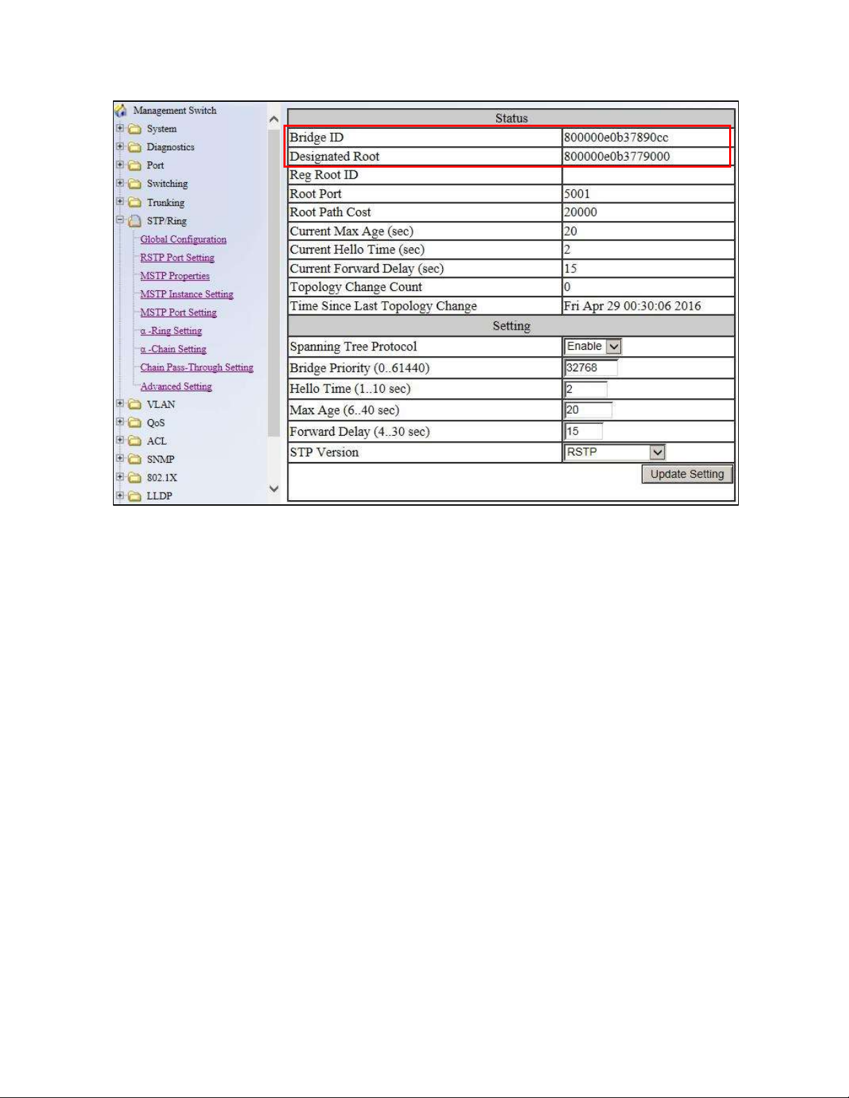
Figure 39: Bridge ID Display
EX77900 Series Managed Switch Users Guide
76
Page 77

Setting the MAX Age, Forward Delay and Hello Timer
To navigate to the STP/Ring Global Configuration page:
1. Click on the + next to STP/Ring.
2. Click on Global Configuration.
The Network Diameter
The Diameter of a network depends on the type of topology your network uses. In a ring
topology, the Network Diameter is the total number of switches in a network minus the
Root Bridge. In a star topology, the Network Diameter is the maximum number of hops
to get from Root Bridge to the switch that is the most hops away. the In the RSTP
protocol, the Max Age parameter is used as a hop count limit on how far the Spanning
Tree protocol packet can propagate throughout the network topology, therefore, it must
be configured with a value that is greater than the network diameter.
Relationship between Max Age, Forward Delay and Hello Time
The following rules must be followed when setting the Max Age, Forward Delay and
Hello Timer:
Max Age >= 2 × (Hello Time + 1.0 second)
2 × (Forward Delay – 1.0 second) >= Max Age
To change the Max Age, Forward Delay and Hello Timer (see Figure 40):
1. Enter the Max Age in the text box to the right of Max Age (6..40 sec) label.
2. Enter the Hello Time in the text box to the right of the Hello Time (1..10 sec)
label.
3. Enter the Forward Delay in the text box to the right of the Forward Delay (4..30
sec) label.
4. Click on the Update Setting button.
5. Save the configuration (see the Save Configuration Page)
77
EX77900 Series Managed Switch Users Guide
Page 78

Figure 40: Max Age, Hello Timer & Forward Delay
RSTP Port Setting Page
To navigate to the STP/Ring RSTP Port Setting page:
1. Click on the + next to STP/Ring.
2. Click on RSTP Port Setting.
Spanning Tree Port Roles
In a stable RSTP topology, each port on a switch can function in any one of 4 different
Spanning Tree port roles. These Spanning Tree port roles are (see Figure 41):
Root Port
Designated Port
Alternate Port
Backup Port
78
EX77900 Series Managed Switch Users Guide
Page 79

Link speed
Recommended value
Less than or equal 100Kb/s
200,000,000
1 Mb/s
20,000,000
10 Mb/s
2,000,000
100 Mb/s
200,000
1 Gb/s
20,000
10 Gb/s
2,000
100 Gb/s
200
1 Tb/s
20
10 Tb/s
2
Figure 41: Spanning Tree Port Roles
Path Cost & Port Priority
By default, each port on a Spanning Tree switch will be assigned a Path Cost based on
the port’s transmission speed according to the IEEE standard below:
By default each port on a Spanning Tree switch will be assigned a Port Priority of
128, according to the IEEE standard. This Port Priority is part of the Port ID, which is
a concatenation of 2 values: Port Priority (4 bits) + Interface ID (12 bits) (see below)
79
EX77900 Series Managed Switch Users Guide
Page 80

Figure 42: Port ID
Port Priority is part of the Port ID, which is a concatenation of 2 values: Port Priority
(4 bits) + Interface ID (12 bits).
The default values will work fine in most scenarios; however, there are times when
you may need to adjust these values manually in order to influence the location of
the Alternate Port, the Root Port or the Backup Port.
To adjust the Port Priority value or the Path Cost value on a port:
1. Choose the correct port from the drop down list under Port (see below)
2. Enter the proper value under the Priority (Granularity 16)
a. The Port Priority range is between 0 and 240 in multiples of 16.
3. Enter the proper value under the Admin. Path Cost text entry box.
a. The Path Cost range is between 1 and 200,000,000.
4. Click on the Update Setting button
5. Save your configuration (see the Save Configuration Page).
Figure 43: Port Priority and Path Cost
Point to Point Link
By default, RSTP will assume any full-duplex link as a Point to Point Link, but if the
switch detects that the neighbor switch is not running the RSTP protocol, it will assume
the port to be a Shared Port. You can force a port to be a Shared Port, if you know in
advance that there will be more than one switch connecting to this link (through an
unmanaged switch, for example), or if you know in advance that the other switch on this
link will be running the older STP protocol.
EX77900 Series Managed Switch Users Guide
80
Page 81

To manually force a port to be a Shared Port or a Point to Point Link:
1. Choose the correct port from the drop down list under Port, and choose Enable
or Disable under Point to Point Link (see Figure 43).
2. Click on the Update Setting button.
3. Save the configuration (see the Save Configuration Page)
Edge Port
By enabling the Edge Port feature on a port, the switch will stop reacting to any linkup
event on this port, and will not send out any Topology Change notification to the
neighbor bridges.
1. Choose the correct port from the drop down list under Port, and choose Enable
or Disable under Edge Port (see Figure 43).
2. Click on the Update Setting button.
3. Save the configuration (see the Save Configuration Page)
RSTP Configuration Examples Using CLI Commands
Enabling the Spanning Tree Protocol
To enable the Spanning Tree function on a switch, use the following CLI commands:
CLI Command Mode: Global Configuration Mode
CLI Command Syntax:
no bridge shutdown 1
bridge 1 protocol rstp vlan-bridge
Usage Example:
switch_a(config)#no bridge shutdown 1
switch_a(config)#bridge 1 protocol rstp vlan-bridge
Bridge Priority, Max Age, Forward Delay, and Hello Time
To configure the Bridge Priority, Max Age, Forward Delay, and Hello Time of a Spanning
Tree Bridge, please use the following CLI commands:
CLI Command Mode: Global Configuration Mode
EX77900 Series Managed Switch Users Guide
81
Page 82

CLI Command Syntax:
bridge 1 priority <0-61440>
bridge 1 max-age <6-40>
bridge 1 forward-time <4-30>
bridge 1 hello-time <1-10>
Usage Example:
switch_a(config)#bridge 1 priority 4096
switch_a(config)#bridge 1 max-age 20
switch_a(config)#bridge 1 forward-time 15
switch_a(config)#bridge 1 hello-time 2
Modifying the Port Priority and Path Cost
To modify the Port Priority and Path Cost on a switch, use the below CLI commands:
CLI Command Mode: Interface Configuration Mode
CLI Command Syntax:
bridge-group 1 path-cost <1-200000000>
bridge-group 1 priority <0-240>
Usage Example:
switch_a(config-if)#bridge-group 1 path-cost 200000
switch_a(config-if)#bridge-group 1 priority 128
Manually Setting a Port to be a Shared or Point to Point Link
To manually force a port to be a shared link or Point-to-point link, use the below CLI
commands:
CLI Command Mode: Interface Configuration Mode
CLI Command Syntax:
spanning-tree link-type point-to-point
spanning-tree link-type shared
Usage Example 1: Setting port 1 to be point-to-point:
switch_a(config-if)#spanning-tree link-type point-to-point
Usage Example 2: Setting port 1 to be shared:
switch_a(config-if)#spanning-tree link-type shared
EX77900 Series Managed Switch Users Guide
82
Page 83

Enabling/Disabling a port to be an Edge Port
To manually enable or disable a port to be an Edge Port, use the following CLI commands:
CLI Command Mode: Interface Configuration Mode
CLI Command Syntax:
spanning-tree edgeport
no spanning-tree edgeport
Usage Example 1: Enabling edge port on port 1:
switch_a(config-if)#spanning-tree edgeport
Usage Example 2: Disabling edge port on port 1:
switch_a(config-if)#no spanning-tree edgeport
STP/RING PAGE - CONFIGURING MSTP
The MSTP protocol adds a new concept called a Region to the Spanning Tree algorithm.
Unlike RSTP and STP, inside each MSTP Region, there can be more than one instance of
Spanning Tree Protocol running simultaneously. The MSTP protocol can then map multiple
VLANs to each instance of Spanning Tree protocol to provide load balancing among the
switches. Between Regions, the MSTP runs a single instance of Spanning Tree similar to,
and is backward compatible with, the RSTP protocol.
Global Configuration Page
Enabling the MSTP Protocol
Navigate to the STP/Ring Global Configuration page:
1. Click on the + next to STP/Ring.
2. Click on Global Configuration.
3. Verify that the Spanning Tree Protocol is enabled (see Figure 44), if not, choose
Enabled from the Spanning Tree Protocol drop down list.
4. Choose MSTP in the STP Version drop down list.
5. Click on the Update Setting button.
6. Save the configuration (see the Save Configuration Page).
EX77900 Series Managed Switch Users Guide
83
Page 84

Figure 44: Enabling MSTP on STP/Ring Global Configuration Page
The CIST Root Bridge & Backup CIST Root Bridge
In order to configure a switch to be the CIST Root Bridge of a Spanning Tree network, you
just have to make sure that the Bridge Priority (which is the most significant 4 bits of the
Bridge ID) of the switch is the lowest among any of the switches on the network. Similarly for
the Backup CIST Root Bridge, it must have the next lowest Bridge Priority of all the switches.
This Bridge ID is a concatenation of 3 values: a 4 bit Bridge Priority (most significant), a 12
bit System ID (less significant), and the 48 bit MAC address of the local switch (least
significant) (see below).
Figure 45: Bridge ID
84
EX77900 Series Managed Switch Users Guide
Page 85

Setting Bridge Priority
To set the Bridge Priority:
1. Enter the Bridge Priority ID in the text box to the right of Bridge Priority
(0..61440)
2. Click on the Update Setting button.
Note: The valid values for this parameter are from 0 to 61440, in increments of
4096; you will see this value reflected in the first hexadecimal digit of the Bridge ID field
after you click the Update Setting button (See Figure 46). Set this value to be less than
any other switch on the network, in order to make this switch the Root Switch. To set a
Backup Root Bridge set the Bridge ID to be between the Root Bridge and the rest of
the network switches.
Figure 46: Bridge ID Display
85
EX77900 Series Managed Switch Users Guide
Page 86

Configuring the CST Network Diameter
When using MSTP, the Max Age parameter is used for the CST (Common Spanning Tree)
topology simply as a hop count limit on how far the Spanning Tree protocol packet can
propagate throughout the CST topology, therefore, the Max Age must be configured with a
value that is greater than the network diameter of the CST topology. The Max Age
parameter will need to be configured correctly on both the CIST Root Bridge as well as on
the Backup CIST Root Bridge (in the event when the CIST Root Bridge fails).
Setting the MAX Age, Forward Delay and Hello Timer
Navigate to the STP/Ring Global Configuration page:
1. Click on the + next to STP/Ring.
2. Click on Global Configuration.
Relationship between Max Age, Forward Delay and Hello Time
The following rules must be followed when setting the Max Age, Forward Delay and
Hello Timer:
Max Age >= 2 × (Hello Time + 1.0 second)
2 × (Forward Delay – 1.0 second) >= Max Age
To change the Max Age, Forward Delay and Hello Timer (see Figure 47):
1. Enter the Max Age in the text box to the right of Max Age (6..40 sec) label.
2. Enter the Hello Time in the text box to the right of the Hello Time (1..10 sec)
label.
3. Enter the Forward Delay in the text box to the right of the Forward Delay (4..30
sec) label.
4. Click on the Update Setting button.
5. Save the configuration (see the Save Configuration Page)
EX77900 Series Managed Switch Users Guide
86
Page 87

Figure 47: Max Age, Hello Timer & Forward Delay
MSTP Properties Page
Configuring an MSTP Region
In order to form a MSTP Region, the switches that will be connected together to form the
MSTP Region must have the same values for the configuration parameters listed below.
Two of the parameters can be configured directly, the third parameter (Configuration Digest)
will be automatically calculated by the switch based on the VLAN to MSTI (Multiple
Spanning Tree Instance) mapping. The VLAN to MSTI instance mapping must be the
same for all the switches within the same MSTP Region (see MSTP Instance Setting Page).
Region name
Revision level
Configuration Digest
To navigate to the STP/Ring MSTP Properties page:
1. Click on the + next to STP/Ring.
EX77900 Series Managed Switch Users Guide
87
Page 88

2. Click on MSTP Properties.
To configure both the MSTP Regional Configuration Name and the Revision Level for each
of the switches located in the same MSTP Region (see below):
1. Enter the Region Name of the Region that the switch will belong to in the Region
Name text entry box,
2. Enter the Revision Level value for the corresponding Region in the Revision Level
text entry box,
3. Click on the Update Setting button.
4. Save the configuration (see the Save Configuration Page)
Figure 48: MSTP Region and Revision Level
88
EX77900 Series Managed Switch Users Guide
Page 89

Configuring the IST Network Diameter
To navigate to the STP/Ring MSTP Properties page:
1. Click on the + next to STP/Ring.
2. Click on MSTP Properties.
In the MSTP protocol, the Max Hops parameter is used for the IST (Internal Spanning Tree)
and the MSTI (Multiple Spanning Tree Instance) topology as a hop count limit on how far the
Spanning Tree protocol packet can propagate inside of a MSTP Region, therefore, it must
be configured with a value that is greater than the network diameter of the IST/MSTI
topology. The Max Hops parameters should be configured correctly on the CIST Root and
the Backup CIST Root switch and on all of the Boundary switches of a MSTP Region (if
there are multiple Regions within your MSTP network).
Follow the steps below to configure the Max Hops parameter:
1. Enter the desired hop count in the text entry box next to Max Hops
2. Click on the Update Setting button (see below).
3. Save the configuration (see the Save Configuration Page)
Figure 49: MSTP Properties – Max Hops
89
EX77900 Series Managed Switch Users Guide
Page 90

MSTP Instance Setting Page
Setting an MSTP Instance
Navigate to the STP/Ring MSTP Instance Setting page:
1. Click on the + next to STP/Ring.
2. Click on MSTP Instance Setting.
To create the Spanning Tree instances to be run inside a MSTP Region and its VLAN
mappings, follow the below steps.
1. Click on the VLAN Instance Configuration button (see Figure 50),
2. Choose the VLAN that you want to map to a MSTI instance from the VLAN ID drop
down box (see Figure 51).
3. Enter the Instance ID that you want the VLAN to map to In the text entry box next to
Instance ID (1..15).
4. Click on the Update Settings button.
5. Save the configuration (see the Save Configuration Page)
Note: You can enter a new instance number here, which is how a new MSTI instance
is created. You can use an existing MSTI instance if it has already been created on
another switch.
EX77900 Series Managed Switch Users Guide
90
Page 91
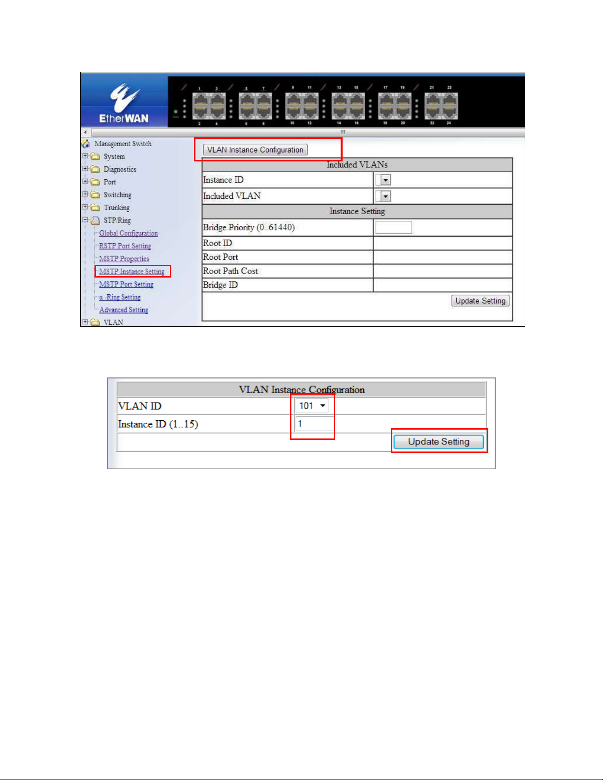
Figure 50: VLAN Instance Configuration
Figure 51: VLAN Instance ID
Modifying MSTP parameters for load balancing
To navigate to the STP/Ring MSTP Instance Setting page:
1. Click on the + next to STP/Ring.
2. Click on MSTP Instance Setting.
To load balance switches within a MSTP Region, set different switches within the MSTP
Region to be the Root Bridge for different MSTI instances. A Root Bridge in a particular
MSTI instance is called a MSTI Regional Root Bridge.
EX77900 Series Managed Switch Users Guide
91
Page 92
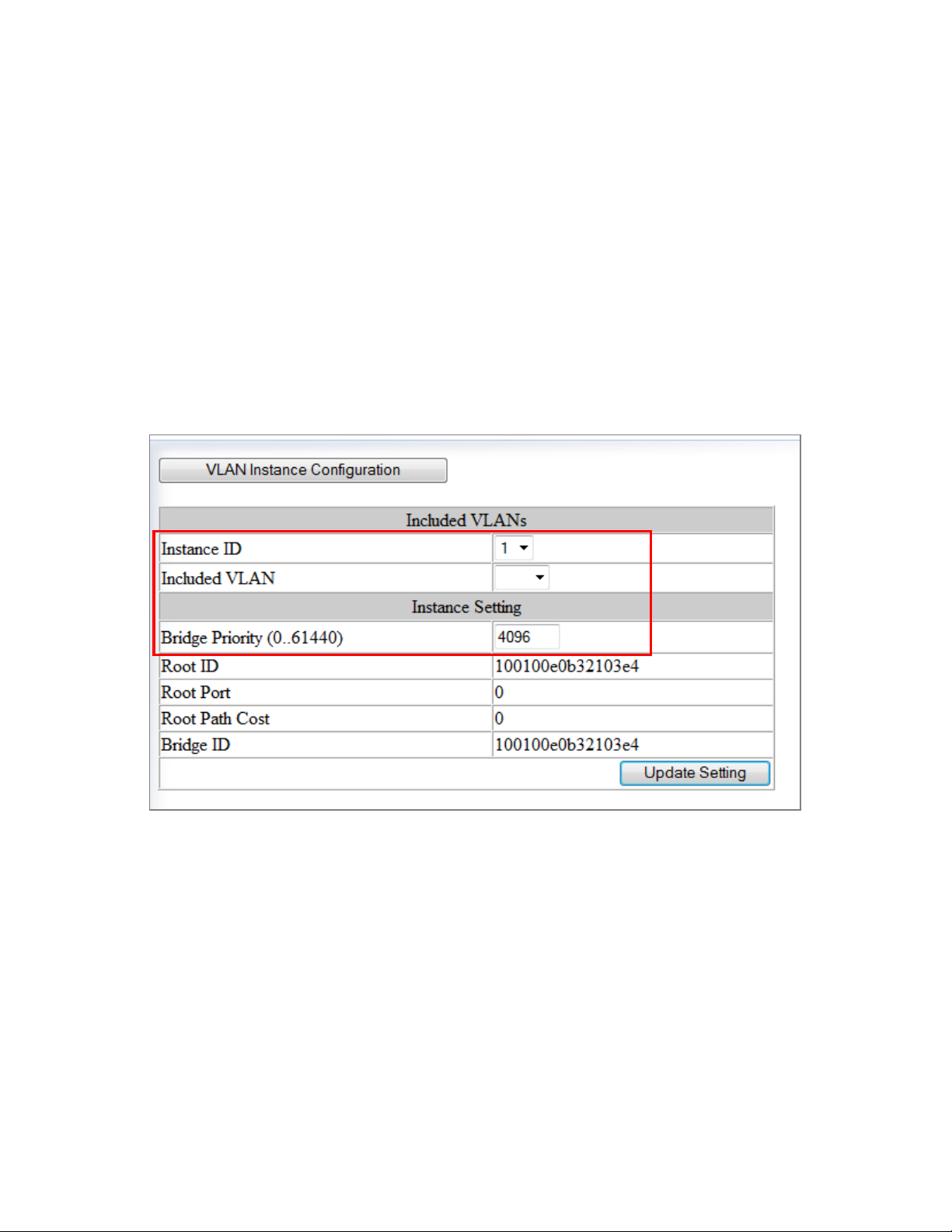
To designate a specific switch in a MSTP Region to be the Root Bridge in a specific MSTI
instance, the bridge priority must be set to be the lowest number of all the switches in a
particular MSTI instance.
To set the bridge priority on the switch for a specific MSTI Instance (see Figure 52):
1. Choose the particular instance in the Instance ID drop down list for which the switch
will be a MSTI Regional Root Bridge;
2. Enter the desired value in the Bridge Priority text box
3. Click on the Update Setting button. The valid values for this parameter are from 0 to
61440, in increments of 4096.
4. Save the configuration (see the Save Configuration Page)
Figure 52: Setting the MSTI Regional Root Bridge
MSTP Port Setting page
Adjusting the blocking port in a MSTP network
To navigate to the STP/Ring MSTP Port Setting page:
1. Click on the + next to STP/Ring.
2. Click on MSTP Port Setting.
EX77900 Series Managed Switch Users Guide
92
Page 93

You can adjust the location of the blocking port in a MSTP network by modifying the Port
Priority and the Path Cost of the ports on the switch. Modifying the Port Priority adjusts
the blocking port between two switches. Modify the Port Cost adjusts the location of the
blocking port in a MSTP loop.
To modify the Port Priority and the Path Cost of the ports on a MSTP switch for the MSTI
instance only, please follow the below steps:
1. Choose the correct MSTI Spanning Tree instance from the drop down list under
Instance ID (see Figure 53).
2. Choose the correct port number from the drop down list under Port, and enter the
proper value under the Priority and the Admin. Path Cost text box,
3. Click on the Update Setting button (see Figure 53).
4. Save the configuration (see the Save Configuration Page)
Figure 53: Port Cost & Priority
MSTP Instance Port Membership
To navigate to the STP/Ring MSTP Port Settings page:
1. Click on the + next to STP/Ring.
EX77900 Series Managed Switch Users Guide
93
Page 94

2. Click on MSTP Port Setting.
If changes have been made to the port membership of a VLAN, you must also reconfigure
the MSTP port membership for the MSTP instance that the VLAN maps to.
To reconfigure the MSTP instance port membership:
1. Click on the Port Instance Configuration button (see Figure 54)
2. Choose the correct MSTP instance from the drop down list next to Instance ID (see
Figure 55).
3. Check the box next to all the ports that should be part of this instance
4. Click on the Update Setting button.
5. Save the configuration (see the Save Configuration Page)
Figure 54: Port Instance Configuration
EX77900 Series Managed Switch Users Guide
94
Page 95

Figure 55: Port Instance - Adding Ports
MSTP Configuration Examples Using CLI Commands
Enabling Spanning Tree for MSTP
To enable the Spanning Tree function on a switch use the below CLI commands.:
CLI Command Mode: Global Configuration Mode
CLI Command Syntax:
no bridge shutdown 1
bridge 1 protocol mstp
Usage Example:
switch_a(config)#no bridge shutdown 1
switch_a(config)#bridge 1 protocol mstp
Bridge Priority, Max Age, Forward Delay, and Hello Time
To configure the CIST Bridge Priority, Max Age, Forward Delay, and Hello Time of a
Spanning Tree Bridge, use the following CLI commands:
CLI Command Mode: Global Configuration Mode
CLI Command Syntax:
bridge 1 priority <0-61440>
bridge 1 max-age <6-40>
EX77900 Series Managed Switch Users Guide
95
Page 96

bridge 1 forward-time <4-30>
bridge 1 hello-time <1-10>
Usage Example:
switch_a(config)#bridge 1 priority 4096
switch_a(config)#bridge 1 max-age 20
switch_a(config)#bridge 1 forward-time 15
switch_a(config)#bridge 1 hello-time 2
IST MAX Hops
To configure the IST Max Hops parameter on a switch, use the following CLI commands:
CLI Command Mode: Global Configuration Mode
CLI Command Syntax: bridge 1 max-hops <1-40>
Usage Example:
switch_a(config)#bridge 1 max-hops 20
MSTP Regional Configuration Name and the Revision Level
To configure both the MSTP Regional Configuration Name and the Revision Level on a
switch, use the following CLI commands:
CLI Command Mode: MSTP Configuration Mode
CLI Command Syntax:
bridge 1 region <region_name>
bridge 1 revision <revision_number>
Usage Example:
switch_a(config)#spanning-tree mst configuration
switch_a(config-mst)#bridge 1 region R1
switch_a(config-mst)#bridge 1 revision 0
Creating an MSTP Instance
To create a MSTP instance and map it to a VLAN, use the following CLI commands:
EX77900 Series Managed Switch Users Guide
96
Page 97

CLI Command Mode: MSTP Configuration Mode
CLI Command Syntax: bridge 1 instance <1-15> vlan <vlan_ID>
Usage Example:
switch_a(config)#spanning-tree mst configuration
switch_a(config-mst)#bridge 1 instance 1 vlan 10
Setting MSTP Priority
To set the MSTI priority of a switch in a MSTP Region, use the following CLI commands:
CLI Command Mode: Global Configuration Mode
CLI Command Syntax: bridge 1 instance <1-15> priority <0-61440>
Usage Example:
switch_a(config)#bridge 1 instance 1 priority 0
Modifying CIST Port Priority and Port Path Cost
To modify the CIST Port Priority and CIST Port Path Cost on a switch, use the below CLI
commands:
CLI Command Mode: Interface Configuration Mode (port)
CLI Command Syntax:
bridge-group 1 path-cost <1-200000000>;
bridge-group 1 priority <0-240>
Usage Example:
switch_a(config-if)#bridge-group 1 path-cost 200000
switch_a(config-if)#bridge-group 1 priority 128
To modify the MSTP Port Priority and MSTP Port Path Cost for an Instance on a switch,
please use the below CLI commands:
CLI Command Mode: Interface Configuration Mode
EX77900 Series Managed Switch Users Guide
97
Page 98

CLI Command Syntax:
bridge-group 1 instance <1-15> path-cost <1-200000000>
bridge-group 1 instance <1-15> priority <0-240>
Usage Example:
switch_a(config-if)# bridge-group 1 instance 1 path-cost 20000
switch_a(config-if)# bridge-group 1 instance 1 priority 128
Adding a Port to an MSTP Instance
To add a port to a MSTP instance (this port must be a member port of the VLAN that is
mapped to the MSTP instance), please use the below CLI commands:
CLI Command Mode: Interface Configuration Mode
CLI Command Syntax: bridge-group 1 instance <1-15>
Usage Example:
switch_a(config-if)#bridge-group 1 instance 1
STP/RING PAGE - ALPHA RING
Alpha Ring Setting Page
To navigate to the STP/Ring α-Ring Settings page:
1. Click on the + next to STP/Ring.
2. Click on α-Ring Setting.
EtherWAN α-Ring Technology
The α-Ring protocol was designed and developed by EtherWAN to overcome traditional
STP and RSTP’s inability to provide fast network recovery and minimize packet loss caused
by link failure. Among the advantages of α-Ring are:
98
EX77900 Series Managed Switch Users Guide
Page 99

High-speed Recovery – Less than 15 milliseconds
Flexibility for Network Deployment – Coexistence with STP, RSTP, and MSTP
Ring Coupling – Smaller rings coupled together to increase network efficiency
Implementing a Simple α-Ring
1. Change the Ring State to Enabled
2. Click on the Update Setting button.
Next, the ports that will be used to connect this switch to the α-Ring need to be assigned to
provide the connection redundancy.
1. Change Ring Port 1 to the port you will be using for the first redundant connection
2. Change Ring Port 2 to the port you will be using for the second redundant
connection.
3. Click on the Update Setting button.
4. Save the configuration
Figure 56: α-Ring Settings
EX77900 Series Managed Switch Users Guide
99
Page 100

Connecting two α-Ring Networks together
To navigate to the STP/Ring α-Ring Settings page:
1. Click on the + next to STP/Ring.
2. Click on α-Ring Setting.
As additional switches are added to a network, it may become necessary to connect multiple
α-Ring networks together. This is called Ring-coupling and uses two additional Ethernet
ports on the switch. To setup Ring-coupling (see Figure below):
1. Change the Ring-coupling state to Enable.
2. Click on the Update Setting button next to the Ring-coupling state.
3. Choose the desired port from the drop-down list under Ring Coupling Port 1
4. Choose the desired port from the drop-down list under Ring Coupling Port 2
5. Click on the Update Setting button.
6. Save the configuration.
Figure 57: Ring Coupling
STP/RING PAGE - ADVANCED SETTING
To navigate to the STP/Ring Advanced Setting page:
1. Click on the + next to STP/Ring.
EX77900 Series Managed Switch Users Guide
100
 Loading...