

Page 1
EX49000 www.etherwan.com
Quick Start Guide
This quick start guide describes how to install and use the Hardened
Web-Smart PoE (Power over Ethernet) Ethernet Switch. Port and LED
number will vary on different models. This user's manual will only use
EX49162 to cover all models.
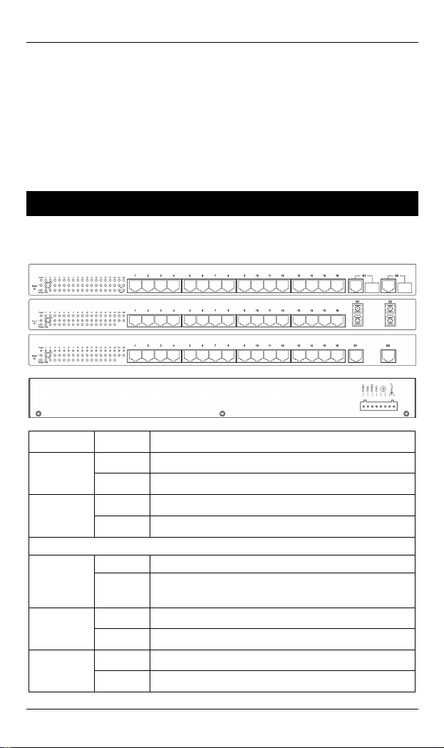
Physical Description
The Port Status LEDs and Power Inputs
LED State Indication
Power1
Power2
Fault
10/100Base-TX
Link/ACT
10/100
PoE
Steady Power on.
Off Power off.
Steady Power redundant system failure occurred.
Off Power redundant system failure is not occurred.
Steady A valid network connection established.
Flashing
Steady Valid port connection at 100Mbps.
Off Valid port connection at 10Mbps.
Steady Powered device (PD) is connected.
Off Powered device (PD) is disconnected.
Transmitting or receiving data.
ACT stands for ACTIVITY.
User’s Manual 1
Page 2
Hardened Web-Smart PoE Ethernet Switch
LED State Indication
Gigabit Ethernet
Stead blished.y A valid network connection esta
Link/A
TX
SFP
CT
Flashi
Steady A valid TX connection established.
Off No valid TX connection established.
Steady connection established. A valid SFP
Off No valid SFP connection established.
Transmitting or receiving data
ng
ACT stands for ACTIVITY.
.
DC T B o wo pairs of
erminal lock P
power inputs c tch. Redundant
power supplies n
an be us
functio is supported.
wer Inputs: There are t
ed to power up this swi
Power Input Ass
Powe
r2
Power1
Relay Output Rating 1A @ 24VDC
ignment
+
47-57VDC
-
P
ower Ground
+
47-57VDC
-
Power Ground
Earth Ground
Terminal Block
The 10/100Base-TX (PoE) and Gigabit Ethernet Connectors
1. The 10/10 a n
The following lists the /100Base-TX ports.
2 User’s Manual
0B se-TX (PoE) Con ections
pinouts of 10
Page 3
EX49000 www.etherwan.com
Pin Signal Name Signal Definition
1
TD+ Output Transmit Data +
2
TD- Output Transmit Data -
3
RD+ Input Receive Data +
4
PoE Positive (VCC+)
5
PoE Positive (VCC+)
6
RD- Input Receive Data -
7
PoE Negative (VCC-)
8
PoE Negative (VCC-)
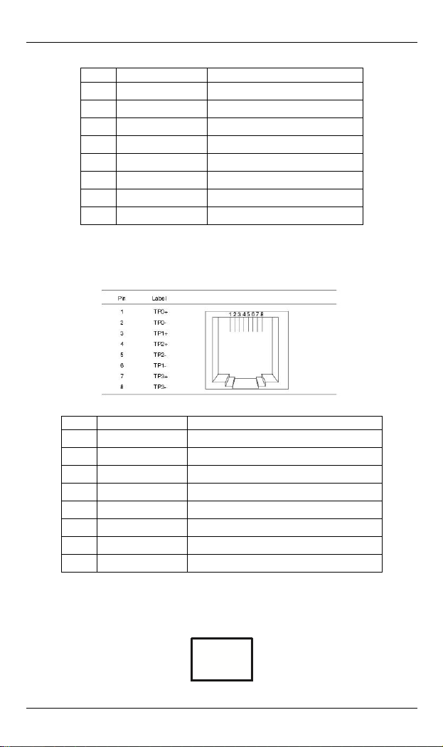
2. The 1 0Ba Connec
The followi lists the pinouts .
00 se-T tions
ng of 1000Base-T ports
Pin Signal Name Signal Definition
1
TP0+ Transmit and Receive Data 0 +
2
TP0- Transmit and Receive Data 0 -
3
TP1+ Transmit and Receive Data 1 +
4
TP2+ Transmit and Receive Data 2 +
5
TP2- Transmit and Receive Data 2 -
6
TP1- Transmit and Receive Data - 1
7
TP3+ Transmit and Receive Data 3 +
8
TP3- Transmit and Receive Data 3 -
3. The SFP t Conn
The SF cket for Gigabit
Socke ections
P so fiber optic expansion.
User’s Manual 3
Page 4
Hardened Web-Smart PoE Ethernet Switch
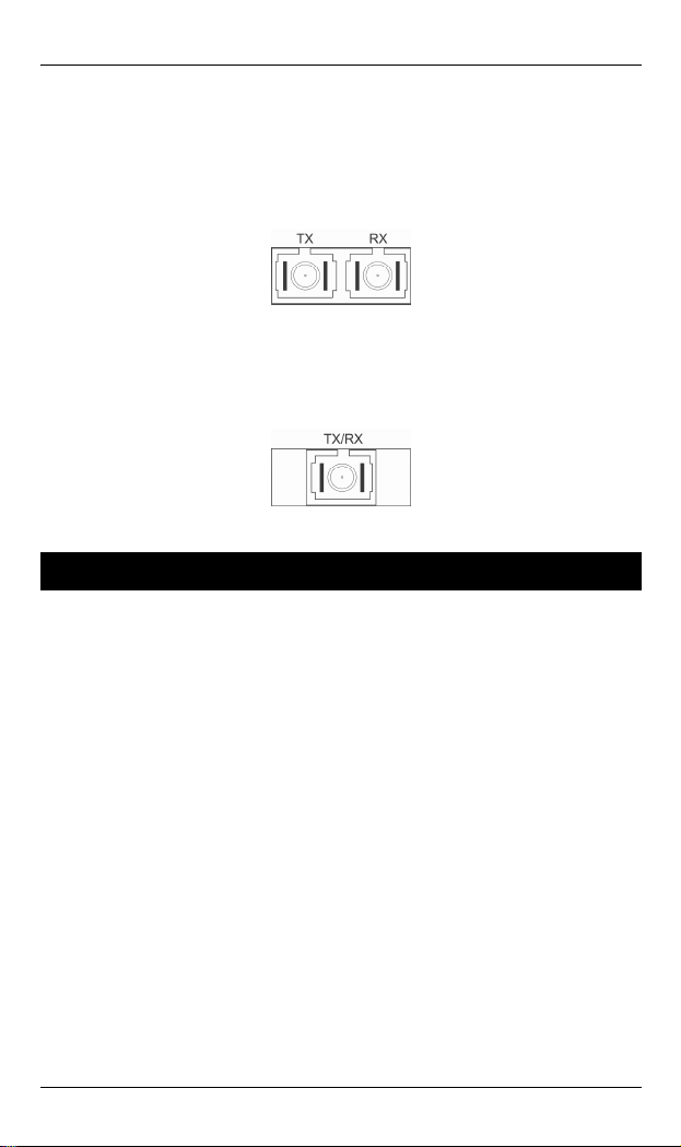
. The 1000Base-SX/LX Connections
4
The fiber port pinouts: The Tx (tran
connected to the Rx (receive) port of device II, a
eceive) port of device I to the Tx (transmit) port of device II.
(r
smit) port of device I is
nd the Rx
5. The WDM 1000Base-BX Connections
The fiber port pinouts: Only one optical fiber is required to
transmit and receive data.
Functional Description
Meets NEMA TS2 Environmental requirements suc h as temperature,
shock, and vibration for traffic control equipment.
Meets EN61000-6-2 & EN61000-6-4 EMC Generic Standard Immunity
for industrial environment.
Manageable via Web browser interface.
Supports IEEE802.3at Power over Ethernet (PoE) Power Sourcing
Equipment (PSE
Up to Max. 16 IEEE802.3at compliant PoE PSE (30W) ports.
2 Gigabit SFP combo ports.
1000Mbps-Full-duplex, 10/100Mbps-Full/Half-duplex.
Auto-Negotiation, Auto-MDI/MDIX.
Supports 4096 MAC addresses. Provides 2.25M bits memory buffer.
Alarms for power and port link failure by r
Power Supply: Redundant 55VDC Terminal Block power inputs.
Device power consumption: 15W Max. (without PoE). PoE power
budget: 480W Max.
).
elay output.
) operating temperature range. -40℃ to 75℃ (-40℉ to 167℉
4 User’s Manual
Page 5
EX49000 www.etherwan.com
Supports Rack Mounting installation.
Web Configuration
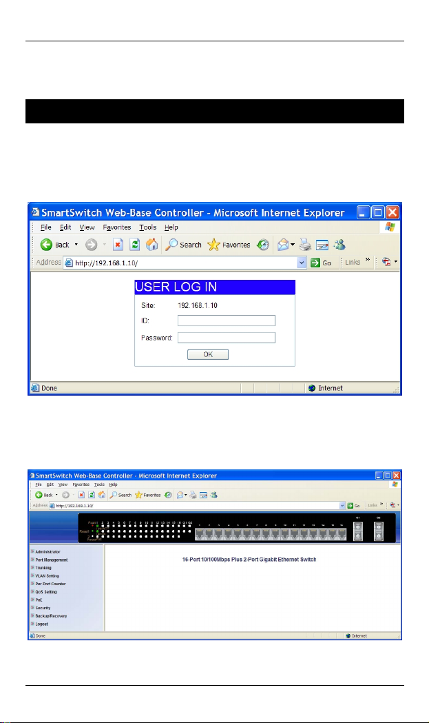
Login the switch:
Specify the default IP address (192.168.1.10) of the switch in the
bro ser. A login w ndow wil be shown as below:
w i l
web
Enter the factory default user name: admin.
Enter the factory default password: admin.
Then click on the “OK” button to log on to the switch.
User’s Manual 5
Page 6

Hardened Web-Smart PoE Ethernet Switch
Preface
This manual describes how to install and use the Hardened
Web-Smart PoE Ethernet Switch. This switch introduced here
is designed to deliver full scalability with web-based
management functions. Capable of operating at temperature
extremes of -40℃ to +75℃, this is the switch of choice for
harsh environments.
P
ort 1 to port 16 on this Switch supports IEEE802.3at Power
over Ethernet (PoE) Power Sourcing Equipment (PSE) and
can detect an IEEE802.3at compliant Powered Device (PD).
Using external 47~57VDC power inputs through Terminal
Block, data and power can be transmitted to a Powered
Device (PD) over the same twisted-pair Ethernet cable
through port 1 to port 16 on the Switch.
To get the most out of this manual, you should have an
understanding of Ethernet networking concepts.
In this manual, you will find:
Features on the Hardened Web-Smart PoE Ethernet Switch
Illustrative LED functions
Installation instructions
Management Configuration
Specifications
6 User’s Manual
Page 7

EX49000 www.etherwan.com
Table of Contents
Quick Start Guide 1
PHYSICAL DESCRIPTION 1
The Port Status LEDs and Power Inputs 1
The 10/100Base-TX (PoE) and Gigabit Ethernet Connectors 2
FUNCTIONAL DESCRIPTION 4
WEB CONFIGURATION 5
reface P
Table of Contents 7
6
Product Overview 9
HARDENED WEB-SMART POE ETHERNET SWITCH 9
PACKAGE CONTENTS 10
PRODUCT HIGHLIGHTS 10
Basic Features 10
FRONT PANEL DISPLAY
P P 12
HYSICAL ORTS
S
WITCH MANAGEMENT 13
Web-based browser interface 13
nstallation I
SELECTING A SITE FOR THE SWITCH
ONNECTING TO OWER
C P 14
Redundant DC Terminal Block Power Inputs
C Y NONNECTING TO OUR ETWO
Cable Type & Length
Cabling
Switch Management
17
14
ailure Alarms for Power and Port Link F
RK 15
11
14
14
15
15
16
MANAGEMENT ACCESS OVERVIEW 17
WEB MANAGEMENT 18
Web-Based Browser Management 19
LOGGING ON TO THE SWITCH 19
UNDERSTANDING THE BROWSER INTERFACE 20
ADMINISTRATOR 22
Authentication Configuration 22
System IP Configuration 23
System Status 24
Load Default Setting 25
Firmware Update 26
Reboot Device 27
PORT MANAGEMENT 28
Port Configuration 29
User’s Manual 7
Page 8

Hardened Web-Smart PoE Ethernet Switch
Port Mirroring 30
Bandwidth Control
Broadcast Storm Control
Port Alarm Setting
TRUNKING 34
Port Trunking 34
VLAN SETTING 35
VLAN Member Setting (Port Based) 36
Multi to 1 Setting 3
VLAN Member Setting (Tag Based) 40
E
R PORT COUNTER 4P 1
Port Counter 4 1
QOS SETTING 42
Port Based, 802.1p, IP/DS 43
POE 44
PoE System Setting 44
PoE Port Setting 45
PoE Scheduling 46
SECURITY 48
MAC Address Bindi g
n 48
BACKUP/RECOVERY 49
LOGOUT 50
Sp
e cifications 51
31
32
33
7
Priority Mode 42
8 User’s Manual
Page 9
EX49000 www.etherwan.com
Product Overview
Hardened Web-Smart PoE Ethernet Switch
Front and Back View
User’s Manual 9
Page 10

Hardened Web-Smart PoE Ethernet Switch
Package Contents
When you unpack the product package, you shall find the
items listed below. Please inspect the contents, and report
any apparent damage or missing items immediately to your
authorized reseller.
The Hardened Web-Smart PoE Ethernet Switch
User’s Manual
Product Highlights
asic Features
B
Meets NEMA TS2 Environmental requirements suc
shock, and vibration for traffic control equipment.
Meets EN61000-6-2 & EN61000-6-4 EMC Generic Standard Immunity
for industrial environment.
Manageable via Web browser interface.
Supports IEEE802.3at Power over Ethernet (PoE) Power Sourcing
Equipment (PSE).
Up to Max. 16 IEEE802.3at compliant PoE PSE (30W) ports.
2 Gigabit SFP combo ports.
h as temperature,
1000Mbps-Full-duplex, 10/100Mbps-Full/Half-duplex.
Auto-Negotiation, Auto-MDI/MDIX.
Supports 4096 MAC addresses. Provides 2.25M bits memory buffer.
Alarms for power and port link failure by relay output.
Power Supply: Redundant 55VDC Terminal Block power inputs.
Device power consumption: 15W Max. (without PoE). PoE power
budget: 480W Max.
-40℃ to 75℃ (-40℉ to 167℉) operating temperature range.
Supports Rack Mounting installation.
10 User’s Manual
Page 11

EX49000 www.etherwan.com
Front Panel Display
Power (Power1, Power2)
This LED comes on w
turned on.
Port Status LEDs
The LEDs are located on the front panel, display
respective port.
LED State Indication
Power1
Power2
Fault
10/100Base-TX
Link/ACT
10/100
PoE
Steady Power on.
Off Power off.
Steady Power redundant system failure occurred.
Off Power redundant system failure is not occurred.
Steady A valid network connection established.
Flashing
Steady Valid port connection at 100Mbps.
Off Valid port connection at 10Mbps.
Steady Powered device (PD) is connected.
Off Powered device (PD) is disconnected.
hen the switch is properly connected to power and
Please refer to the following table for more details.
Transmitting or receiving data.
ACT stands for ACTIVITY.
ing status for each
User’s Manual 11
Page 12

Hardened Web-Smart PoE Ethernet Switch
LED State Indication
Gigabit Ethernet
Steady A valid network connection established.
Link/ACT
TX
SFP
Flashing
Steady A valid TX connection established.
Off No valid TX connection established.
Steady A valid SFP connection established.
Off No valid SFP connection established.
Transmitting or receiving data.
ACT stands for ACTIVITY.
Physical Ports
This switch series provides different combinations of RJ-45
opper and fiber poc
16 x 10/100Base-TX PoE ports + 2 x Gigabit Ethernet
ports
12 x 10/100Base-TX PoE ports + 2 x Gigabit Ethernet
rts
po
0/1 s + 2 x Gigabit Ethernet ports
8 x 1 00Base-TX PoE port
CONNECTIVITY
-45 co rs
SC or S nnec
se-BX fiber port.
SC connector on 1000Ba
SFP soc n er port.
nnecto RJ
T co tor on 1000Base-SX/LX fiber port.
ket con ection on 1000Base-SX/LX/BX fib
<Note> Diffe ferent type of fiber
connector.
rent product model supports dif
rts as below:
12 User’s Manual
Page 13

EX49000 www.etherwan.com
Switch Ma
Web-based b
The s also rface that
witch boasts a point-and-click browser-based inte
lets user access full swi from a
Netscape or Internet Ex
nagement
rowser interface
tch configuration and functionality
plorer browser.
User’s Manual 13
Page 14

Hardened Web-Smart PoE Ethernet Switch
Installation
This chapter gives step-by-step instructions about how to
install the switch:
Selecting a Site for the Switch
As with any electric device, you should place the switch
where it will not be subjected to extreme temperatures,
humidity, or electromagnetic interference. Specifically, the
site you select should meet the following requirements:
-The ambient temperature should be between -40℃ to 75℃ (-40℉ to
167℉).
-The relative humidity should be less than 95 percent, non-condensing.
-Surrounding electrical devices should not exceed the electromagnetic field
(RFC) standards.
-Make sure that the switch receives adequate ventilation. Do not block the
ventilation holes on each side of the switch.
-The power outlet should be within 1.8 meters of the switch.
Connecting to Power
Redundant DC Terminal Block Power Inputs:
Redundant DC Terminal Block Power Inputs
There are two pairs of power inputs for use with redundant
power sources. You only need to have one power input
connected to run the switch.
Step 1: Connect the DC power cord to the plug-able terminal block on the
Step 2: Disconnect the power cord if you want to shut down the switch.
14 User’s Manual
switch, and then plug it into a standard DC outlet.
Page 15

EX49000 www.etherwan.com
Back View
Alarms for Power and Port Link Failure
There are two pins on the terminal bloc ed fo
failure detection. Use this as a dry contact applic n to send
a signal for power failure detection.
Power Input Assignment
Power2
Power1
Relay Output Rating 1A @ 24VDC
+
47-57VDC
-
Power Ground
+
47-57VDC
-
Power Grou
Earth Ground
nd
k are us r power
atio
Terminal Block
Connecting to Your Network
Cable Type & Length
It is necessary to follow the cable
the switch to your network. Use ap
and cabling req
able Specifications C
peed Connector Port Speed Cable
S
10Base-T RJ-45 10/20 Mbps 4-pair UTP/STP
100Base-TX RJ-45 100/200 Mbps 4-pair UTP/STP
1000Base-T RJ-45 2000 Mbps 4-pair UTP/STP 100 m
1000Base-SX SC, ST 2000 Mbps MMF (50 or
1000Base SC 2000 Mbps MMF (50 or 2 km -SX
1000Base-LX SC 2000 Mbps SMF (9 or 10μm) 10, 20 km
1000Base-BX SC 2000 Mbps SMF (9 or 10μm) 20 km
User’s Manual 15
uirements.
specifications below when connecting
propriate cables that meet your speed
Half/Full
Duplex
Cat. 3, 4, 5
Cat. 5
Cat. 5
62.5μm)
62.5μm)
Max.
D
100 m
100 m
275, 550 m
istance
Page 16

Hardened Web-Smart PoE Ethernet Switch
SFP
1000Base-SX Duplex LC 2000 Mbps MMF (50 or
62.5μm)
1000Base-LX Duplex LC 2000 Mbps SMF (9μm) 10, 20, 40,
1000Base-BX Single LC 2000 Mbps MMF (50 or
62.5μm)
1000Base-BX Single LC 2000 Mbps SMF (9μm) 10, 20 km
275 m, 550
m, 2 km
70 km
550 m
Cabling
Step 1: First, ensure the power of the switch and end devices are turned off.
<Note> Alw u a is off before any installation.
Step 2: Prepare cable t connectors for each type of port
Step 3: Consult Cable Sp le on previous section for cabling
Step 4: Connect one end of the cable to the switch and the other end to a
Step 5: Once the connections between two end devices are made
ays ens re th t the power
wi h corresponding
use.
in
ecifications Tab
requirements based on connectors and speed.
desired device.
successfully, turn on the power and the switch is operational.
16 User’s Manual
Page 17

EX49000 www.etherwan.com
Switch Management
This chapter s ods to
config a nt a the It desc
ure m nageme
types of managem ns an communication
a
nd management protocols that deliver data between your
manageme
the system
options.
This chapter covers the following topics:
explain the meth that you ca
ccess to
ent a
pplicatio
nt device (workstation or personal computer) and
. It also contains information about port connection
switch
d the
.
n use
ribes the
• Management Access Overview
• Key Concepts
•
Key Guidelines for Implementation
• Web Management Access
•
Manag
The switch gives you the flexibility to access and manage the
switch using any or all of the following methods.
The web browser interface support is embedded in the switch
software and is available for immediate use.
tandards, Protocols, and Related Rea
S ding
ement Access Overview
User’s Manual 17
Page 18

Hardened Web-Smart PoE Ethernet Switch
Web Management
The switch provides a browser interface that lets you
configure and manage the switch remotely.
After you set up your IP address for the switch, you can
access the switch’s web interface applications directly in your
web browser by entering the IP address of the switch. You
an then use your web browser to list and manage switch
c
configuration parameters from one centr
ou were directly connected to the switch’s console port.
y
al location, just as if
18 User’s Manual
Page 19

EX49000 www.etherwan.com
Web-Based Browser Management
The switch provides a web-based browser interface for
configuring and managing the switch. This interface allows
you to access the switch using a preferred we
This chapter describes how to configure the switch using its
web-based browser interface.
Logging on to the switch
b browser.
SWITCH IP ADDRESS
your web browser, specify the IP address of the switch. Default IP address
In
is 192.168.1.10.
USER NAME
Enter the factory default user name: admin.
PASSWORD
Enter the factory default password: admin.
enter a user-defined password if you followed the instructions later and
Or
changed the factory default password.
Then click on the “OK” button to log on to the switch.
User’s Manual 19
Page 20

Hardened Web-Smart PoE Ethernet Switch
Understanding the Browser Interface
The web browser interface provides groups of point-and-click
buttons at the left field of the screen for configuring and
anaging the switch. m
Administrator
Authentication Configuration, System IP Configuration, System Status, Load
Default Setting, Firmware Update, Reboot Device
Port Management
Port Configu
Control, Port Alarm Setting
Trunking
Port T
VLAN Setting
VLAN Mode, V
Per Port Counter
P
ort Counte
QoS Setting
Priorit
P
oE
PoE S
20 User’s Manual
ration, Port Mirroring, Bandwidth Control, Broadcast Storm
runking
L
AN Member Setting, Multi to 1 Setting
r
y Mode, Port Based, 802.1p, IP/DS
ystem Setting, PoE Port Setting, PoE Schedulin
g
Page 21

EX49000 www.etherwan.com
Security
MAC Address Binding
Backup/Recovery
Logout
User’s Manual 21
Page 22

Hardened Web-Smart PoE Ethernet Switch
Administrator
Authentication Configuration
1. Username: Click in “Username” text box and type in a new username.
2. Password: Click in “Password” text box and type in a new password.
3. Confirm: Click in “Confirm” text box. Type the same password in
“Password” text box again to verify it.
4. Update: Click “Update” button to update your settings.
<Note> Username & Password can only use “a-z”, “A-Z”, “0-9”, “_”, “+”, “-”,
and “=”.
22 User’s Manual
Page 23

EX49000 www.etherwan.com
System IP Configuration
1. IP Address: Click in “IP Address” text box and type a new address to
change the IP Address.
2. Subnet Mask: Click in “Subnet Mask” text box and type a new address
to change the Subnet Mask.
3. Gateway: Click in “Gateway” text box an
the Gateway.
4. Update: Click “Update” button to update your settings.
d type a new address to change
User’s Manual 23
Page 24

Hardened Web-Smart PoE Ethernet Switch
System Status
1. Comment: Click in “Comment” text box and type a new comment for this
Switch.
2. Idle Time Security: Click and choose “Idle Time Security” to enable or
disable protection security for managing the Switch after a period of idle
time.
3. Idle Time (1~3
time. This is for protection security to manage the Switch af
of idle time.
4. Auto Logout (Default): Click and choose “Auto Logout” to automatically
log the user out after a period of idle time. And this is the default setting
for Idle Time Security.
5. Back to the last display: Click and choose “Back to the last display” to
back to the last displayed web screen before a period of idle time.
6. Update: Click “Update” button to update your settings.
<Note> Comment name can only use “a-z”, “A-Z”, “0-9”, “_”, “+”, “-”, and
“=”.
0 Minutes): Click in “Idle Time” text box and type an idle
ter a period
24 User’s Manual
Page 25

EX49000 www.etherwan.com
Load Default Setting
Load: Click “Load” button to restore the default setting of the Switch including
the IP Address, User Name, and Password.
User’s Manual 25
Page 26

Hardened Web-Smart PoE Ethernet Switch
Firmware Update
1. Password: Click in “Password” text box and type in the password.
2. ReConfirm: Click in “ReConfirm” text box. Type the same password in
“Password” text box again to verify it.
3. Update: Click “Update” button to continue the Firmware Update process.
26 User’s Manual
Page 27

EX49000 www.etherwan.com
Reboot Device
Confirm: Click “Confirm” button to reboot the Switch.
User’s Manual 27
Page 28

Hardened Web-Smart PoE Ethernet Switch
Port Management
28 User’s Manual
Page 29

EX49000 www.etherwan.com
Port Configuration
1. Tx/Rx Ability: Click “Tx/R
or “Disable” from the “Tx
transmitting/receiving ability for the port.
2. Auto-Negotiation: Click “Auto-Negotiation” drop-down menu to choose
“Enable” or “Disable” from the “Auto-Negotiation” drop-down list to
enable or disable auto-negotiation for the port.
3. Speed: Click “Speed” drop-down menu to choose “1G”, “100M”, or
“10M” from the “Speed” drop-down list to change the line speed for the
port.
4. Duplex: Click “Duplex” drop-down menu to choose “Full” or “Half” from
the “Duplex” drop-down list to set Full Duplex mode or Half Duplex
mode for the port.
5. Pause: Click “Pause” drop-down menu to choose “Enable” or “Disable”
from the “Pause” drop-down list to enable or disable pause function for
the port.
6. Backpressure: Click “Backpressure” drop-down menu to choose
“Enable” or “Disable” from the “Backpressure” drop-down list to enable
or disable backpressure function for the port.
7. Addr. Learning: Click “Addr. Learning” drop-down menu to choose
“Enable” or “Disable” from the “Addr. Learning” drop-down list to enable
or disable MAC address learning function for the port.
8. Select Port No.: By clicking the checking box of the port to select the
port to be configured the functions above.
9
. Update: Click “Update” button to update your settings.
10. Refresh: Click “Refresh” button to refresh port configuration information.
x Ability” drop-down menu to choose “Enable”
/Rx Ability” drop-down list to enable or disable
User’s Manual 29
Page 30

Hardened Web-Smart PoE Ethernet Switch
Port Mirroring
1. Dest Port: By clicking the checking box to select the destination port.
2. Monitored Packets: Click “Monitored Packets” drop-down menu to
Choose “Disable”, “Rx”, “Tx”, or “Tx & Rx” from “Monitored Packets”
drop-down list.
3. Source Port: By clicking the checking box to select the source port.
4. Update: Click “Update” button to update your settings.
30 User’s Manual
Page 31

EX49000 www.etherwan.com
Bandwidth Control
1. Port No: Click “Port No” drop-down menu to choose port from “Port No”
drop-down list.
2. TX Rate: Set the transmission rate for the port.
3. RX Rate: Set the receiving rate for the port.
4. Speed Base:
Low: 32Kbps Tx/Rx bandwidth resolution for port 1 ~ port 18. Actual
Tx/Rx bandwidth = Rate value x 32Kbps. The rate value is 1~255.
High:
Port 1 ~ port 16: 256Kbps Tx/Rx bandwidth resolution for port 1 ~ port
16. Actual Tx/Rx bandwidth = Rate value x 256Kbps. The rate value is
1~255. The rate value is 1~39 when link speed is 10MB.
Port 17 ~ port 18: The bandwidth resolution is 2048Kbps for port 17 ~
port 18. Actual Tx/Rx bandwidth = Rate value x 2048Kbps. The rate
value is 1~255. The rate value is 1~4 when link speed is 10MB. The
rate value is 1~48 when link speed is 100MB.
5. Update: Click “Update” button to update your settings.
6. LoadDefault: Click “LoadDefault” button to load default settings.
<Note> This system will use the link speed as user’s setting if the link speed
of selected port is lower than the rate set by user.
User’s Manual 31
Page 32

Hardened Web-Smart PoE Ethernet Switch
Broadcast Storm Control
1. Threshold: Set the threshold for port from 1~63.
2. Enable Port: By clicking the checking box to select the port.
3. Update: Click “Update” button to update your settings.
32 User’s Manual
Page 33

EX49000 www.etherwan.com
Port Alarm Setting
1. Port: Click “Port” drop-down menu to choose port from the “Port”
drop-down list.
2. Trigger Enabled: Click “Trigger Enabled” drop-down menu to choose
“YES” or “NO” from the “Trigger Enabled” drop-down list to enable or
disable Trigger.
3. Update: Click “Update” button to update settings to the switch.
User’s Manual 33
Page 34

Hardened Web-Smart PoE Ethernet Switch
Trunking
Port Trunking
1. Trunk Hash Algorithm Selection: Click and choose “Port ID”, “SA”, “DA”,
or “SA & DA” Trunk Hash Algorithm.
2. Trunk0: Click and choose Port1 ~
3. Trunk1: Click and choos
4. Update: Click “Update” butt
e Port5 ~ Port8 to be added into the Trunk1.
Port4 to be added into the Trunk0.
on to update your settings.
34 User’s Manual
Page 35

EX49000 www.etherwan.com
VLAN Setting
There are two VLAN m
Click “Change VLAN m
<Note> Tag Based VLAN and Multi to 1 setting function will be disabled
automatically if the Port Based VLAN func
User’s Manual 35
odes: Port Based VLAN and Tag Based VLAN.
ode” to select the mode.
tion is enabled.
Page 36

Hardened Web-Smart PoE Ethernet Switch
VLAN Member Setting (Port Based)
1. Port: Click “Port” drop-down menu to choose port from the “Port”
drop-down list.
2. Read: Click “Read” button to read the VLAN member setting information
of the port.
3. Dest PORT: Click and choose ports to be added to VLAN member.
4. Update: Click “Update” button to update your settings.
5. LoadDefault: Click “LoadDefault” button to load default settings.
36 User’s Manual
Page 37

EX49000 www.etherwan.com
Multi to 1 Setting
choose destination port from the “Destination PortNo.” drop-down list.
2. Disable Port: Click and choose the port which you don’t want to use.
3. Update: Click “Update” button to update your settings.
User’s Manual 37
.” drop-down menu to 1. Destination PortNo.: Click “Destination PortNo
Page 38

Hardened Web-Smart PoE Ethernet Switch
Click “Change VLAN mode” to change to Tag Based VLAN mode.
Change to Tag Based VLAN mode if you click on “Continue” button.
Otherwise, click on “Back” button to cancel.
38 User’s Manual
Page 39

EX49000 www.etherwan.com
. Tag Mode: Click and choose “AddTag”, “don’t care”, or “RemoveTag” fo1 r
ports.
. Update: Click “Update” button to update your settings. 2
User’s Manual 39
Page 40

Hardened Web-Smart PoE Ethernet Switch
VLAN Member Setting (Tag Based)
1. VID: Enter a VLAN ID entry (1~4094).
2. Add: Press “Add” button to add a VLAN ID entry.
3. VID: Click “VID” drop-down menu to choose VLAN ID entry from the
“VID” drop-down list.
4. Delete: Press “Delete” button to remove a selected VLAN ID entry.
5. Update: Click “Update” button to update your settings.
6. VID Source port: Click and choose VLAN ID source port. This VLAN ID
will be treated as a VLAN ID embedded in an 802.1Q tag if you don not
select any port.
<Note> Please don’t add VLAN tag on your control port.
40 User’s Manual
Page 41

EX49000 www.etherwan.com
Per Port Counter
Port Counter
1. Counter Mode Selection: Click “Counter Mode Selection” drop-d
menu to choose “Transmit Packet & Receive Packet”, “
Transmit Packet”, “Drop Packet & Receive Packet”, or “CRC error
Packet & Receive Packet” from the “Counter Mode Selection”
drop-down list.
. Update: Click “U2
3. Clear: Click “Clear” button to clear port counter inform
. Refresh: Click “Refresh” button to refresh port counter information.4
User’s Manual 41
pdate” button to update your settings.
Collision Cou
ation.
own
nt &
Page 42

Hardened Web-Smart PoE Ethernet Switch
QoS Setting
Priority Mode
1. First-In-First-Out: First received packet will be transmitted first.
2. All-High-before-Low: Packets set in high priority mode will be
transmitted first before packets set in low priority mode.
3. Weight-Round-Robin: Set the ratio of the transmitting packet for the low
priority to high priority.
4. Update: Click “Update” button to update your settings.
42 User’s Manual
Page 43

EX49000 www.etherwan.com
Port Based, 802.1p, IP/DS
1. Port Based: Click and select the port which you want to configure as
high priority. It means the packet of the port will be transmitted first.
2. VLAN Tag: Click and select the port which you want to configure as high
priority. The VLAN Tag
0~3.
. IP/DS: Click and select the port which you want to configure as 3
priority. The IP/DS priority class: High priority (DEC): 10, 18, 26, 34, 46,
56. Low priority: others.
4. Update: Click “Update” button to update your settings.
priority class: High priority: 4~7. Low priority:
high
User’s Manual 43
Page 44

Hardened Web-Smart PoE Ethernet Switch
PoE
PoE System Setting
1. System power budget: Click in “System power budget” text box and type
a new system power budget.
Update: Click “Update” button to update your settings. 2.
44 User’s Manual
Page 45

EX49000 www.etherwan.com
PoE Port Setting
1. Port: Click “Port” drop-down menu to choose port from the “Port”
drop-down list.
2. Enable Mode: Click “Enable Mode” drop-down menu to choose “Enable”,
“Disable”, or “Scheduling from the “Enable Mode” drop-down list to
enable, disable, or schedule port to discover Powered Device (PD)
connected to port of the Switch.
3. Fix Power Limit(W): Click in “Fix Power Limit(W)” text box and type a
new fixed power limit for port to provide power to PD.
4. Power Priority: Click “Power Priority” drop-down menu to choose “Low”,
“Middle”, or “High” from the “Power priority” drop-down list to determine
power priority of port.
5. Update: Click “Update” button to update your settings.
User’s Manual 45
Page 46

Hardened Web-Smart PoE Ethernet Switch
PoE Scheduling
Adjust RTC Time: Adjust system time for this Switch.
1. Year(2000-2037): Click in “Year” text box and specify year 2000 to 2037.
2. Month: Click in “Month” text box and specify 1 to 12.
3. Day: Click in “Day” text box and specify 1 to 31. Click drop-down menu
to choose “Mon” to “Sun” from the drop-down list.
4. Hour: Click in “Hour” text box and specify 0 to 23.
5. Minute: Click in “Minute” text box and specify 0 to 59.
6. Second: Click in “Second” text box and specify 0 to 59.
7. Update: Click “Update” button when you finished Adjust RTC Time.
1. Port: Click “Port” drop-down menu to choose port from the “Port”
drop-down list.
. Day: Click “Day” drop-down menu to choose “Mon” to “Sun2 ” from the
“Day” drop-down list.
3. Time: Click the “Time” check box to enable PoE scheduling to this port
during these time periods.
4. Update: Click “Update” button to update your settings.
Status
1. Port: Click “Port” drop-down menu to choose port from the “Port”
46 User’s Manual
Page 47

EX49000 www.etherwan.com
drop-down list.
2. Update: Click “Update” button to update the PoE Schduling status of this
port.
User’s Manual 47
Page 48

Hardened Web-Smart PoE Ethernet Switch
Security
MAC Address Binding
1. MAC Address: Set MAC address to be activated on the selected port.
2. Read: Click “Read” button to read the MAC address binding information
of the port.
3. Select Port: Click “Select Port” drop-down menu to choose port from the
“Select Port” drop-down list.
4. Binding: Click “Binding” drop-down menu to choose “Enable” or
“Disable” from the “Binding” drop-down menu. Click the “Enable” check
box to enable Port Security for each port. The MAC address learning
function will be disabled for the port automatically if you enable the MAC
address binding function.
5. Update: Click “Update” button to update your settings.
<Note> Please don’t enable MAC address binding on your control port.
48 User’s Manual
Page 49

EX49000 www.etherwan.com
Backup/Recovery
Backup(Switch→PC): Click “Download” button to download EEPROM
contents.
Recovery(PC→Switch)
1. Select the image file: Click “Browse” button to select the image file to be
recovered to the Switch.
2. Password: Click in “Password” text box and type in the password.
confirm the recovery process. 3. Update: Click “Update” button to
User’s Manual 49
Page 50

Hardened Web-Smart PoE Ethernet Switch
Logout
1. Accept: Click “Accept” button to logout of the Switch.
2. Back: Click “Back” button to cancel the logout of the Switch.
50 User’s Manual
Page 51

EX49000 www.etherwan.com
Specifications
Applicable Standards
Switching Method Store-and-Forward
Forwarding Rate
10Base-T
100Base-TX
1000Base-T/SX/LX
Performance
Cable
10Base-T
100Base-TX
1000Base-T
1000Base-SX/LX/BX
LED Indicators Per unit – Power status (Power1, Power2), Fault
Dimensions 442mm (W) x 205mm (D) x 44.2mm (H)
Net Weight 3Kg (6.61lbs.)
Power Input
Operating Voltage &
Max. Current
Consumption
Power Consumption
Operating
Temperature
Storage Temperature
Humidity 5%-95% non-condensing
EMI FCC Part 15, Class A
EMS EN61000-6-2:
Environmental Test
Compliance
NEMA TS2 Environmental requirements for traffic control equipment
IEEE802.3 10Base-T
IEEE802.3u 100Base-TX/FX
IEEE802.3ab 1000Base-T
IEEE802.3z 1000Base-SX/LX
10/20Mbps half / full-duplex
100/200Mbps half / full-duplex
2000Mbps full-duplex
14,880pps for 10Mbps
148,810pps for 100Mbps
1,488,100pps for 1000Mbps
4-pair UTP/STP Cat. 3, 4, 5 Up to 100m (328ft)
4-pair UTP/STP Cat. 5 Up to 100m (328ft)
4-pair UTP/STP Cat. 5 Up to 100m (328ft)
MMF (50 or 62.5μm), SMF (9 or 10μm)
Per port –
10/100TX: Link/ACT, 10/100, PoE
Gigabit Ethernet: Link/ACT, TX, SFP
(17.4” (W) x 8.07” (D) x 1.73” (H))
Terminal Block: 55VDC
9A @ 55VDC
495W Max.
-40℃ to 75℃ (-40℉ to 167℉)
-40℃ to 85℃ (-40℉ to 185℉)
EN61000-6-4: EN55022, EN61000-3-2, EN61000-3-3
EN61000-4-2 (ESD Standard)
EN61000-4-3 (Radiated RFI Standards)
EN61000-4-4 (Burst Standards)
EN61000-4-5 (Surge Standards)
EN61000-4-6 (Induced RFI Standards)
EN61000-4-8 (Magnetic Field Standards)
IEC60068-2-6 Fc (Vibration Resistance)
IEC60068-2-27 Ea (Shock)
FED STD 101C Method 5007.1 (Free Fall w/ package)
User’s Manual 51
 Loading...