

Page 1

EX39924 www.etherwan.com
Quick Start Guide
This quick start guide describes how to install and use the
Industrial Gigabit Ethernet Switch. This is the switch of choice
for harsh environments.
Functional Description
1000Mbps-Full-duplex, 10/100Mbps-Full/Half-duplex,
Auto-Negotiation, Auto-MDI/MDIX.
Supports 8192 MAC addresses. Provides 512KB buffer
memory.
None-blocking architecture and full wire-speed
forwarding rate.
Supports IEEE802.3x Flow Control for Full-duplex and
Back Pressure for Half-duplex.
Supports IEEE802.3az Energy Efficient Ethernet (EEE)
standards on copper ports.
Supports Quality of Service (QoS) based on layer 2
priorities.
Jumbo frame supports up to 16379 Bytes.
100~240VAC, 50~60Hz internal universal PSU.
-10°C to 60°C (14°F to 140°F) operating temperature
range.
Supports Rack Mounting installation.
1
Page 2
EX39924 www.etherwan.com
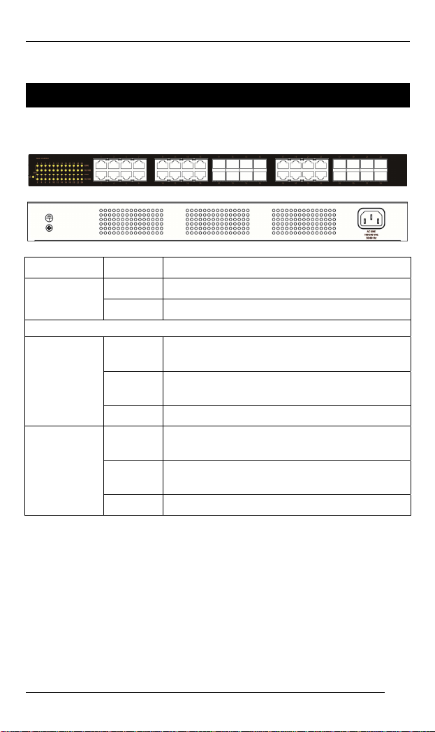
Physical Description
The Port Status LEDs and Power Inputs
LED State Indication
Power
10/100/1000Base-TX / SFP Ports
Link/Act
10/100Base
(Green)
Link/Act
1000Base
(Green)
Steady Power on.
Off Power off.
Steady
Flashing
Off No valid network connection established.
Steady
Flashing
Off No valid network connection established.
A valid network connection established at
10/100Mbps.
Transmitting or receiving data.
Act stands for Activity.
A valid network connection established at
1000Mbps.
Transmitting or receiving data.
Act stands for Activity.
The 10/100/1000Base-TX and Gigabit SFP Connectors
The 10/100/1000Base-TX Connections
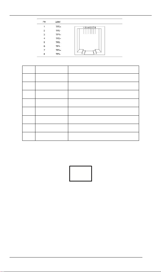
The following lists the pinouts of 10/100/1000Base-TX ports.
2
Page 3
EX39924 www.etherwan.com
Pin Signal Name Signal Definition
TP0+ Transmit and Receive Data 0 +
1
TP0- Transmit and Receive Data 0 -
2
TP1+ Transmit and Receive Data 1 +
3
TP2+ Transmit and Receive Data 2 +
4
TP2- Transmit and Receive Data 2 -
5
TP1- Transmit and Receive Data 1 -
6
TP3+ Transmit and Receive Data 3 +
7
TP3- Transmit and Receive Data 3 -
8
The SFP Socket Connections
The SFP socket for SFP optic modules.
3
Page 4

EX39924 www.etherwan.com
Preface
A member of the growing family of rugged switches, this
Industrial Gigabit Ethernet Switch provides an affordable
solution for rugged and outdoor environment, transportation
road-side cabinet, industrial floor shop, multitenant dwellings
or Fiber To The Home (FTTH) applications. Capable of
operating at temperature extremes of -10
the switch of choice for harsh environments.
Port 9 to port 24 on this Switch supports 16-port combo SFP
slots. This manual describes how to install and use the
Industrial Gigabit Ethernet Switch. This switch integrates full
wire speed switching technology. This switch brings the
answer to complicated hardened networking environments.
To get the most out of this manual, you should have an
understanding of Ethernet networking concepts.
In this manual, you will find:
Features on the switch
Illustrative LED functions
Installation instructions
Specifications
°C to +60°C, this is
4
Page 5

EX39924 www.etherwan.com
Table of Contents
QUICK START GUIDE 1
FUNCTIONAL DESCRIPTION 1
PHYSICAL DESCRIPTION 2
The Port Status LEDs and Power Inputs 2
The 10/100/1000Base-TX and Gigabit SFP Connectors 2
REFACE 4
P
T
ABLE OF CONTENTS 5
RODUCT OVERVIEW 6
P
INDUSTRIAL GIGABIT ETHERNET SWITCH 6
PACKAGE CONTENTS 6
PRODUCT HIGHLIGHTS 7
Basic Features 7
FRONT PANEL DISPLAY 8
PHYSICAL PORTS 8
INSTALLATION 9
SELECTING A SITE FOR THE SWITCH 9
CONNECTING TO POWER 9
AC Inlet Power Socket 9
CONNECTING TO YOUR NETWORK 10
Cable Type & Length 10
Cabling 10
SPECIFICATIONS 11
5
Page 6

EX39924 www.etherwan.com
Product Overview
Industrial Gigabit Ethernet Switch
Package Contents
When you unpack the product package, you shall find the
items listed below. Please inspect the contents, and report
any apparent damage or missing items immediately to your
authorized reseller.
This Switch
User’s Manual
6
Page 7

EX39924 www.etherwan.com
Product Highlights
Basic Features
1000Mbps-Full-duplex, 10/100Mbps-Full/Half-duplex,
Auto-Negotiation, Auto-MDI/MDIX.
Supports 8192 MAC addresses. Provides 512KB buffer
memory.
None-blocking architecture and full wire-speed
forwarding rate.
Supports IEEE802.3x Flow Control for Full-duplex and
Back Pressure for Half-duplex.
Supports IEEE802.3az Energy Efficient Ethernet (EEE)
standards on copper ports.
Supports Quality of Service (QoS) based on layer 2
priorities.
802.1Q VLAN Tag Based Priority, Class of
Service.
Output Queue Schedule Mode: Weighted Round
Robin (WRR) with 2 priority queues.
The configurations of QoS are as below:
CoS Field Value Packet Count Priority
0, 1, 2, 3 1 Low
4, 5, 6, 7 2 High
Jumbo frame supports up to 16379 Bytes.
100~240VAC, 50~60Hz internal universal PSU.
-10°C to 60°C (14°F to 140°F) operating temperature
range.
Supports Rack Mounting installation.
7
Page 8

EX39924 www.etherwan.com
Front Panel Display
Status LEDs
LED State Indication
Power
10/100/1000Base-TX / SFP Ports
Link/Act
10/100Base
(Green)
Link/Act
1000Base
(Green)
Steady Power on.
Off Power off.
Steady
Flashing
Off No valid network connection established.
Steady
Flashing
Off No valid network connection established.
A valid network connection established at
10/100Mbps.
Transmitting or receiving data.
Act stands for Activity.
A valid network connection established at
1000Mbps.
Transmitting or receiving data.
Act stands for Activity.
Physical Ports
This switch series provides:
24-port Industrial Gigabit Ethernet Switch with 16-port combo
SFP slots.
Connectivity:
RJ-45 connectors.
SFP socket connection on 1000Base-SX/LX/BX fiber
ports.
8
Page 9

EX39924 www.etherwan.com
Installation
This chapter gives step-by-step instructions about how to
install the switch:
Selecting a Site for the Switch
As with any electric device, you should place the switch
where it will not be subjected to extreme temperatures,
humidity, or electromagnetic interference. Specifically, the site
you select should meet the following requirements:
The ambient temperature should be between -10 to 60
degrees Celsius.
The relative humidity should be less than 95 percent,
non-condensing.
Surrounding electrical devices should not exceed the
electromagnetic field (RFC) standards.
Make sure that the switch receives adequate ventilation.
Do not block the ventilation holes on each side of the
switch
The power outlet should be within 1.8 meters of the
switch.
Connecting to Power
AC Inlet Power Socket
Connect the supplied AC power cord to the receptacle on the
back of the switch, and then plug it into a standard AC outlet
with a voltage range from 100 to 240 VAC.
9
Page 10

EX39924 www.etherwan.com
Connecting to Your Network
Cable Type & Length
It is necessary to follow the cable specifications below when
connecting the switch to your network. Use appropriate
cables that meet your speed and cabling requirements.
Cable S ecifications p
Speed
Connector Port Speed
Half/Full
Duplex
10Base-T RJ-45 10/20 Mbps 4-pair UTP/STP
100Base-TX RJ-45 100/200 Mbps 4-pair UTP/STP
1000Base-T RJ-45 2000 Mbps 4-pair UTP/STP
SFP
1000Base-SX Duplex LC 2000 Mbps MMF (50 or
1000Base-LX Duplex LC 2000 Mbps SMF (9μm) 10, 20, 40,
1000Base-BX Single LC 2000 Mbps MMF (50 or
1000Base-BX Single LC 2000 Mbps SMF (9μm) 10, 20 km
Cable
Cat. 3, 4, 5
Cat. 5
Cat. 5
62.5μm)
62.5μm)
Max.
Distance
100 m
100 m
100 m
275 m, 550
m, 2 km
70 km
550 m
Cabling
Step 1: First, ensure the power of the switch and end devices are turned off.
<Note> Always ensure that the power is off before any installation.
Step 2: Prepare cable with corresponding connectors for each type of port
Step 3: Consult the previous section for cabling requirements based on
Step 4: Connect one end of the cable to the switch and the other end to a
Step 5: Once the connections between two end devices are made
in use.
connectors and speed.
desired device.
successfully, turn on the power and the switch is operational.
10
Page 11

EX39924 www.etherwan.com
Specifications
Industrial Gigabit
Ethernet Switch
Applicable Standards IEEE 802.3 10Base-T
Switching Method Store-and-Forward
Forwarding Rate
10Base-T:
100Base-TX:
1000Base-T/SX/LX:
Performance 14,880pps for 10Mbps
Cable
10Base-T:
100Base-TX:
1000Base-T:
1000Base-SX/LX/BX:
LED Indicators Per unit – Power
Dimensions 440mm (W) × 210mm (D) × 44mm (H)
Net Weight 2.9Kg (6.4lbs.)
Power 100 – 240VAC, 50 – 60Hz Internal Universal
Operating
Temperature
Storage Temperature
Humidity 5%-95% non-condensing
24-port Industrial Gigabit Ethernet Switch with
16-port combo SFP slots
IEEE 802.3u 100Base-TX
IEEE 802.3ab 1000Base-T
IEEE 802.3z 1000Base-SX/LX
IEEE 802.1x Full-duplex Flow Control
IEEE 802.1az Energy Efficient Ethernet
IEEE 802.1p Quality of Service (QoS)
10 / 20Mbps half / full-duplex
100 / 200Mbps half / full-duplex
2000Mbps full-duplex
148,810pps for 100Mbps
1,488,100pps for 1000Mbps
4-pair UTP/STP Cat. 3, 4, 5
4-pair UTP/STP Cat. 5
4-pair UTP/STP Cat. 5
Up to 100m (328ft)
MMF (50 or 62.5μm), SMF (9 or 10μm)
Per port – Link/Act
(17.32” (W) × 8.19” (D) × 1.73” (H))
PSU
-10°C to 60°C (14°F to 140°F)
-10°C to 70°C (14°F to 158°F)
11
Page 12

EX39924 www.etherwan.com
Emission Compliance CE Mark Class A, FCC Part 15 Class A
12
 Loading...