

Page 1

User’s Guide
EX17908 Web-Smart Switch
FastFind Links
Introduction
Unpacking and Installation
Preparing to Configure the Switch
Configuring the Switch
Page 2

All Rights Reserved
Dissemination or reproduction of this document, or its contents, is not authorized except where expressly
permitted. Violators are liable for damages. All rights reserved, for the purposes of patent application or
trademark registration.
Disclaimer of Liability
The information contained in this document is subject to change without notice. EtherWAN is not liable for any
errors or omissions contained herein or for resulting damage in connection with the information provided in this
manual.
Registered Trademarks
The following words and phrases are registered Trademarks of EtherWAN Systems Inc.
EtherOS™
Ethernet to the World™
All other trademarks are property of their respective owners.
Warranty
For details on the EtherWAN warranty replacement policy, please visit our web site at:
https://kb.etherwan.com/index.php?View=entry&EntryID=27
Products Supported by this Manual:
EX17908
Page 3

Revision
Document Version
Date
Description
A
Version 1
08/05/2014
Initial release
Preface
Audience
This guide is designed for the person who installs, configures, deploys, and maintains the Ethernet
network. This document assumes the reader has moderate hardware, computer, and Internet skills.
Document Revision Level
This section provides a history of the revision changes to this document.
Changes in this Revision
N/A - this is first version of this document.
iii
EX17908 Web-Smart Switch User Guide
Page 4
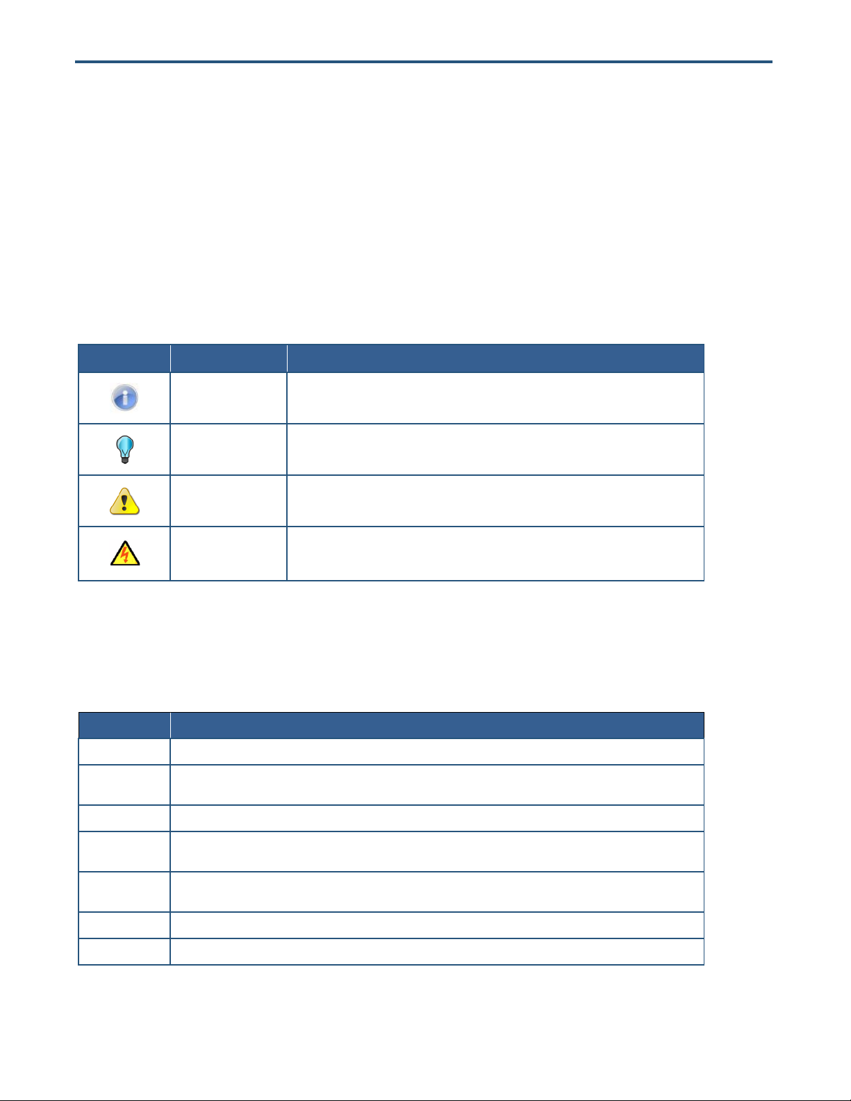
Symbol
Meaning
Description
Note
Notes emphasize or supplement important points of the main text.
Tip
Tips provide helpful information, guidelines, or suggestions for performing tasks more
effectively.
Warning
Warnings indicate that failure to take a specified action could result in damage to the
device, or could result in serious bodily injury.
Electric Shock Hazard
This symbol warns users of electric shock hazard. Failure to take appropriate precautions
such as not opening or touching hazardous areas of the equipment could result in injury or
death.
Convention
Description
Bold
Indicates text on a window, other than the window title, including menus, menu options, buttons, fields, and labels.
Italic
Indicates a variable, which is a placeholder for actual text provided by the user or system. Angled brackets (< >) are
also used to indicate variables.
screen/code
Indicates text that is displayed on screen or entered by the user.
< > angled
brackets
Indicates a variable, which is a placeholder for actual text provided by the user or system. Italic font is also used to
indicate variables.
[ ] square
brackets
Indicates optional values.
{ } braces
Indicates required or expected values.
| vertical bar
Indicates that you have a choice between two or more options or arguments.
Document Conventions
This guide uses the following conventions to draw your attention to certain information.
Safety and Warnings
This guide uses the following symbols to draw your attention to certain information.
Typographic Conventions
This guide also uses the following typographic conventions.
iv
EX17908 Web-Smart Switch User Guide
Page 5

Contents
Preface ..................................................................................................................... iii
Changes in this Revision ............................................................................................. iii
Document Conventions ...............................................................................................iv
Safety and Warnings ...................................................................................................iv
Typographic Conventions ...........................................................................................iv
Contents ................................................................................................................... v
1 Introduction ........................................................................................................... 7
Key Features ............................................................................................................... 8
Quick Start Guide ........................................................................................................ 9
2 Unpacking and Installation ................................................................................ 10
Unpacking the Hardware ........................................................................................... 11
System Requirements ............................................................................................... 11
Hardware Features ................................................................................................... 12
Front Panel .......................................................................................................... 12
Rear Panel .......................................................................................................... 13
Side and Bottom Panels ...................................................................................... 14
Installing the Switch .................................................................................................. 14
Preparing the Site ................................................................................................ 15
Installing the Switch ............................................................................................. 15
Connecting to the 10/100/1000 Mbps RJ-45 Ports ............................................. 16
Checking the Installation ..................................................................................... 17
Applying AC Power ............................................................................................. 17
Where to Go from Here ............................................................................................. 18
3 Preparing to Configure the Switch .................................................................... 19
Connecting the PC .................................................................................................... 20
Configuring TCP/IP Settings for Microsoft Windows 7 .............................................. 20
v
EX17908 Web-Smart Switch User Guide
Page 6

Disabling Proxy Settings ........................................................................................... 22
Disabling Proxy Settings in Internet Explorer ...................................................... 22
Disabling Proxy Settings in Firefox ...................................................................... 23
Disabling Proxy Settings in Safari ....................................................................... 23
Disabling Firewall and Security Software .................................................................. 24
4 Configuring the Switch ....................................................................................... 25
Logging in to the Web Management Interface .......................................................... 26
Inactivity Timeout ...................................................................................................... 27
Understanding the Web Management Interface ....................................................... 27
Web Management Interface Menus .......................................................................... 28
Configuration Menu ............................................................................................. 29
Monitoring Menu .................................................................................................. 53
Maintenance Menu .............................................................................................. 59
5 Troubleshooting ................................................................................................. 65
Troubleshooting Chart ............................................................................................... 66
Additional Troubleshooting Suggestions ................................................................... 67
Network Adapter Cards ....................................................................................... 67
Configuration ....................................................................................................... 67
Switch Integrity .................................................................................................... 67
Auto-Negotiation .................................................................................................. 67
Technology ................................................................................................................ 68
Power ........................................................................................................................ 68
Mechanical ................................................................................................................ 69
Interface .................................................................................................................... 69
Environment .............................................................................................................. 69
Regulatory Approvals ................................................................................................ 69
Index ....................................................................................................................... 71
vi
EX17908 Web-Smart Switch User Guide
Page 7
Topics:
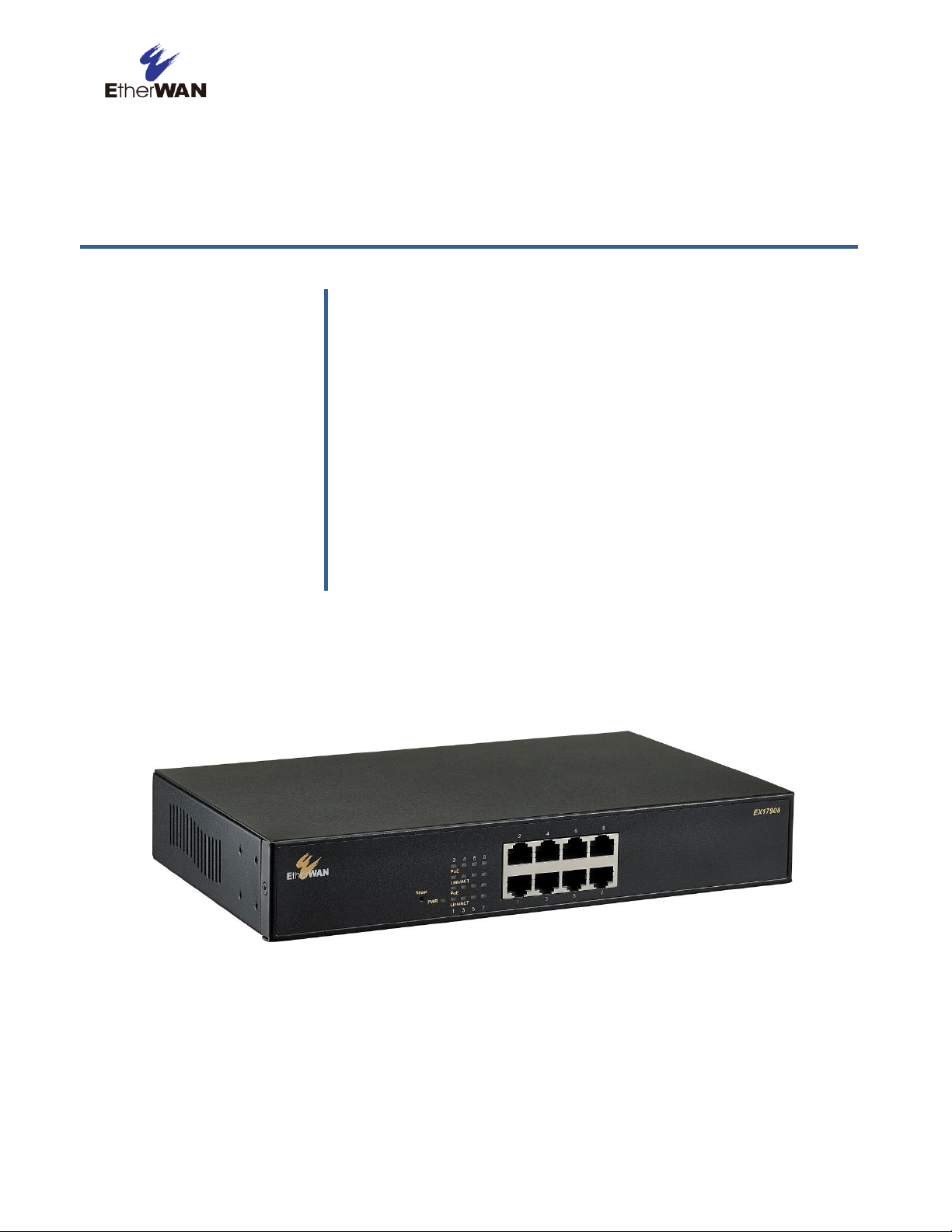
Congratulations on your purchase of the EX17908 Web-Smart
Switch from EtherWAN Systems, Inc. Your EtherWAN switch is a
state-of-the-art IEEE-compliant network solution designed for
users who require high-performance along with the power of
management to eliminate bottlenecks and increase productivity.
Your switch is also a Power Sourcing Equipment (PSE) device. All
10/100/1000 Mbps ports support Power over Ethernet (PoE),
which detects and supplies power with IEEE 802.3af-complaint
powered devices automatically. To simplify installation, the switch
is shipped ready for use.
Key Features (page 8)
Quick Start Guide (page 9)
1 Introduction
Figure 1-1. EX17908 Series Switch
EX17908 Web-Smart Switch User Guide
7
Page 8

Key Features
This section summarizes the key features of the EX17908 switch.
8 10/100/1000BASE-TX ports supporting IEEE 802.3af Power over Ethernet (PoE) Power Sourcing
Equipment (PSE)
PoE power budget up to 30 W/port, with a total power budget of 240 Watts
All 10/100/1000TX ports support full/half-duplex, auto-negotiation, and auto-MDI/MDIX
Web management interface for configuring PoE (power status, link status), system, IP configuration,
port-based VLAN, and QoS priority
QoS support based on IEEE802.1p and DSCP
Jumbo frame support up to 9.6 KB
Port mirroring supported for network traffic monitoring
PoE enable/disable power budget configuration
Back pressure flow control for half-duplex and IEEE 802.3x for full-duplex
100 – 240 VAC, 50 – 60 Hz internal universal power supply
0°C to 40°C (32°F to 104°F) operating temperature range
Supports rack mounting
8
EX17908 Web-Smart Switch User Guide
Page 9

Step
Description
For Reference, See…
1.
Find a Location for the Switch
Set the switch on a flat surface or mount it in a standard rack (1 rack unit high) using the supplied
rack-mounting hardware brackets.
“Preparing the Site” (page 15)
2.
Connect to the 10/100/1000 Mbps Switch Ports
Connect one end of a Category 5 or better Ethernet cable to the Ethernet port of a computer,
printer, network storage, or other network device.
Connect the other end to a 10/100/1000 Mbps RJ-45 port on the switch designated 1 through
8.
Repeat this step for each additional device you want to connect to the 10/100/1000 Mbps
ports.
“10/100/1000 Mbps RJ-45 Ports" (page
12)
and
“Connecting to the 10/100/1000 Mbps
RJ-45 Ports” (page 16)
3.
Power On
Connect the female end of the supplied AC power adapter cable to the power receptacle on
the back of the switch.
Connect the 3-pronged end of the AC power adapter cable to a grounded 3-pronged AC outlet.
Move the ON/OFF switch on the rear panel of the switch to the ON position.
Wait for the switch to complete its Power On Self Test.
Confirm that the LEDs for ports connected to a device are green. If not, replace the Ethernet
cable, and then check the port LED again.
“Applying AC Power” (page 17)
4.
Configure the Switch
Configure a PC for subnet 192.168.2.n, where n is a number other than 1 in the range 0 to 255.
Connect the PC to a 10/100 Mbps RJ-45 port on the switch, launch a browser, and specify the
switch’s default IP address 192.168.2.1.
At the initial page, type admin in the Password field, and then click Apply.
Click Configuration > System.
If your switch will be used with a DHCP server that allocates IP addresses automatically,
check DHCP Enabled. Otherwise, leave DHCP Enabled unchecked and complete the
following fields: Fallback IP Address, Fallback Subnet Mask, and Fallback Gateway.
Next to Name, enter a new case-sensitive username.
Next to Password, enter a new case-sensitive password.
Change any other settings, as necessary.
Click Apply.
Chapters 3 and 4
Quick Start Guide
The following procedure enables advanced users to get their switch up and running in the shortest
possible time. For detailed installation instructions, refer to the sections in the right column below.
EX17908 Web-Smart Switch User Guide
9
Page 10

Topics:
This chapter describes how to unpack and install the EX17908
switch.
Unpacking the Hardware
(page 11)
System Requirements
(page 11)
Hardware Features (page
12)
Installing the Switch (page
14)
Where to Go from Here
(page 18)
2 Unpacking and Installation
EX17908 Web-Smart Switch User Guide
10
Page 11

Unpacking the Hardware
Unpack the items and confirm that no items are missing or damaged. Your package should include:
One EX17908 switch
One external power adapter
Rack-mounting hardware brackets
One CD containing this user’s guide
If any item is damaged or missing, notify your authorized EtherWAN representative. Keep the carton,
including the original packing material, in case you need to store the product or return it.
System Requirements
To complete your installation, you need the following items:
Computer with an Ethernet (RJ-45) Interface
Managing the switch requires a personal or notebook computer (PC) with a 10/100base-TX
Ethernet interface and a physical RJ-45 connection. The preferred operating system for the
computer is Microsoft Windows XP/Vista/7. You can use Apple OSX or Linux systems as well, but
for brevity, all web configurations in this manual use Windows 7 as the underlying operating
system.
Category 5+ Ethernet Cables
An Ethernet cable of at least Category 5 rating is required to connect your PC to the switch. The
cable can be configured as "straight-through" or crossover.
Web Browser Software
Use any of the following web browsers when configuring the switch:
– Internet Explorer
– Mozilla Firefox
– Google Chrome
Internet Explorer is the preferred browser for EtherWAN switch configuration.
11
EX17908 Web-Smart Switch User Guide
Page 12
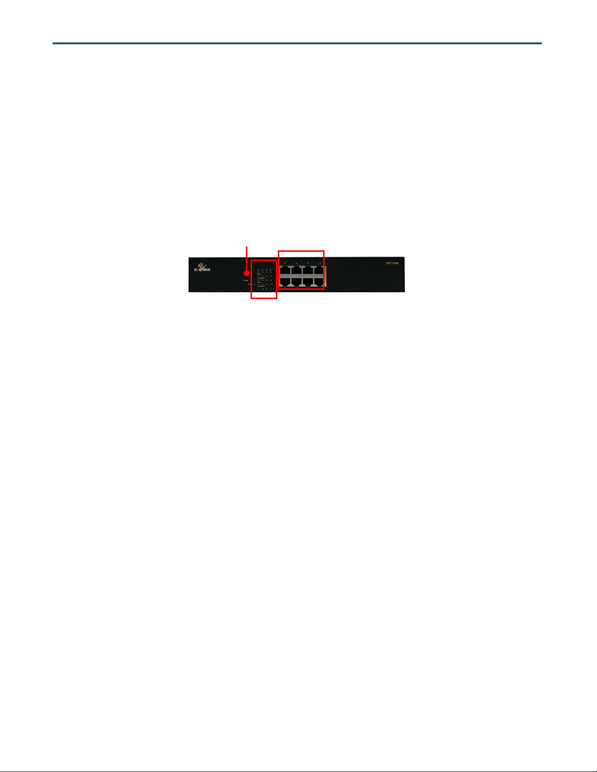
Reset Button
Status
LEDs
10/100 /1000
Mbps Ports
Hardware Features
The following sections describe the hardware features of the EX17908 switch.
Front Panel
Figure 2-1 shows the front panels of the EX17908 switch.
Figure 2-1. Front Panel of the EX17908 Switch
10/100/1000 Mbps RJ-45 Ports
The EX17008 switch has 8 10/100/1000 Mbps RJ-45 ports designated 1 through 8 (see Figure 2-1).
These ports are auto-sensing, auto-MDIX 10/100/1000 Mbps ports.
When you insert a cable into an RJ-45 port, the switch:
Determines whether the cable is a straight-through or crossover cable.
Automatically ascertains the maximum speed (10, 100, or 1000 Mbps) and duplex mode (half- or
full-duplex) of the attached device.
After determining this information, the switch configures the RJ-45 port automatically to enable
communications with the attached device, without requiring user intervention.
Reset Button
The EX17908 front panel has a reset button to reset the switch to its factory default settings. This
button is recessed to prevent accidental resets of the switch.
To reset the switch to its factory default settings and remove all customized overrides you made to the
default settings:
12
EX17908 Web-Smart Switch User Guide
Page 13

Note: You can perform a “warm” restart that reboots the switch and keeps all overrides made
to the switch’s default settings using the Warm Restart page in the switch’s Web management
interface (see “Warm Restart Page” on page 60). You can also return the switch to its factory
default settings using the Factory Default page (see “Factory Default Page” on page 61).
LED
Color
Status
Description
Power
Yellow
ON
Power is supplied to the switch.
PoE
(the port number)
Yellow
ON
Power Device (PD) is connected.
OFF
PD is disconnected.
Link/ACT
(the port number)
Green
ON
A valid network connection has been established.
OFF
Data transmission is not occurring on the port.
Flashing
Data is being sent or received on the port.
1. Leave power cord connected to the switch.
2. Using a pin or paper clip, press and hold the reset button for about 10 seconds, then release the
reset button.
3. Wait for the switch to reboot.
LEDs
The EX17908 front panel LEDs show power, PoE, and link/activity status. Table 2-1 summarizes the
LEDs on the switch.
Table 2-1. Front Panel LEDs
Rear Panel
The EX17908 rear panel has a receptacle for connecting the supplied external power adapter. Use
only the external power adapter supplied with the switch.
The rear panel also has one fan that allows air to pass through the switch enclosure and exit through
the rear of the chassis. Be sure the fan is not blocked.
EX17908 Web-Smart Switch User Guide
13
Page 14

Fan
ON/OFF
Switch
Power
Receptacle
Figure 2-2. Rear Panel of the EX17908 Switch
Side and Bottom Panels
The EX17908 side panels have vents for cooling. Be sure these vents are not blocked.
The bottom panel has a product label that shows regulatory compliance, product serial number, and
other information.
Installing the Switch
Switch installation involves the following steps:
1. Preparing the site. See page 15
2. Installing the switch. See page 15.
3. Connecting to the 10/100 Mbps RJ-45 ports. See page 16.
4. Checking the installation. See page 17.
5. Applying AC power. See page 17.
14
EX17908 Web-Smart Switch User Guide
Page 15

Characteristics
Requirements
Mounting
Desktop installations:
Provide a flat table or shelf surface.
Rack-mount installations:
Use a 19-inch (48.3-centimeter) EIA standard equipment rack that is grounded and physically secure. You
also need the rack-mount guide supplied with your switch.
Access
Locate the switch in a position that lets you access the front panel RJ-45 ports, view the front panel LEDs,
and access the rear-panel power connector.
Power source
Provide a power source within 6 feet (1.8 meters) of the installation location. Power specifications for the
switch are shown in Appendix A. Be sure the AC outlet is not controlled by a wall switch, which can
accidentally turn off power to the outlet and the switch.
Environmental
Temperature:
Install the switch in a dry area, with ambient temperature between 0 and 40ºC (32 and 104ºF). Keep the
switch away from heat sources such as direct sunlight, warm air exhausts, hot-air vents, and heaters.
Operating humidity:
The installation location should have a maximum relative humidity of 90%, non-condensing.
Ventilation:
Do not restrict airflow by covering or obstructing the vents on the rear and side panels of the switch. Keep at
least 2 inches (5.08 centimeters) free on all sides for cooling.
Be sure there is adequate airflow in the room or wiring closet where you intend to install the switch.
Operating conditions:
Keep the switch at least 6 ft (1.83 m) away from nearest source of electromagnetic noise, such as a
photocopy machine.
Stacking
If you intend to stack two or more switches, be sure:
The mounting surface can safely support the stack.
There is adequate space around the stack for ventilation and cooling.
Preparing the Site
Before you install your switch, be sure your operating environment meets the operating environment
requirements in Table 2-2.
Table 2-2. Site Requirements
Installing the Switch
You can install your switch on a flat surface or in a standard EIA 19-inch rack that can be placed in a
wiring closet with other equipment.
If installing the switch on a desktop or shelf, allow sufficient ventilation space between the device
and the objects around it.
If installing the switch in a rack, attach the supplied rack-mounting brackets to the switch's front
panel (one on each side), and secure them with the screws provided with the equipment rack. For
more information, refer to the documentation that came with the equipment rack.
15
EX17908 Web-Smart Switch User Guide
Page 16
Note: PoE faults are caused when noncompliant cabling or powered devices are connected to
a PoE port. Use only standard-compliant cabling to connect IEEE 802.3af-compliant devices to
PoE ports. A cable or device that causes a PoE fault must be removed from the network.
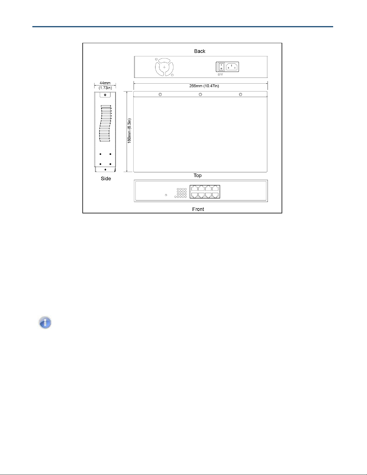
Figure 2-3. EX17908 Switch Dimensions
Connecting to the 10/100/1000 Mbps RJ-45 Ports
The front panel of the switch provides 8 10/100/1000 Mbps RJ-45 ports (see “10/100/1000 Mbps
RJ-45 Ports” on page 12). To prevent ESD damage, follow normal board and component handling
procedures.
To connect devices to the switch’s 10/100/1000 Mbps RJ-45 ports:
1. Insert one end of a Category 5 or better Ethernet cable into a switch port.
2. Insert the other cable end into the Ethernet port of a computer, printer, network storage, or other
network device.
3. Repeat steps 1 and 2 for each additional device you want to connect to the switch.
16
EX17908 Web-Smart Switch User Guide
Page 17

Checking the Installation
Before you apply power:
Inspect the equipment thoroughly.
Verify that all cables are installed correctly.
Check cable routing to make sure cables are not damaged or create a safety hazard.
Be sure all equipment is mounted properly and securely.
Applying AC Power
The EX17908 switch has an ON/OFF switch that controls power to the switch. Before you connect the
power cord, select an AC outlet that is not controlled by a wall switch, which can turn off power to the
switch. After you select an appropriate outlet, use the following procedure to apply AC power.
1. Connect the female end of the supplied AC power adapter cable to the power receptacle on the back
of the switch.
2. Connect the 3-pronged end of the AC power adapter cable to a grounded 3-pronged AC outlet.
3. On the rear panel, move the ON/OFF switch to the ON position ( ).
When you apply power:
All green PoE and Link/ACT LEDs blink momentarily.
The fan starts.
The yellow Power LED goes ON.
The Link/ACT LEDs for every port connected to a device flash, as the switch conducts a brief
Power On Self-Test (POST).
After the switch passes the POST, the Link/ACT LEDs for every port connected to a device go ON.
The PoE LEDs also go ON if Power Devices are connected. The switch is now functional and ready to
pass data.
If you do not hear the fan, or if the Power LED is not ON, check that the power cable is plugged in
correctly, the ON/OFF switch is set to the ON position, and that the power source is good and not
controlled by a wall switch. If this does not resolve the problem, see Chapter 5, Troubleshooting.
17
EX17908 Web-Smart Switch User Guide
Page 18

Where to Go from Here
After you power-up the switch for the first time, you configure it using the switch’s built-in management
software. For more information, see Chapters 3 and 4.
18
EX17908 Web-Smart Switch User Guide
Page 19

Topics:
After you install the switch, configure it using the switch’s built-in
Web management interface and a Web browser on a PC.
For the Web browser to access the switch’s Web management
interface, the PC and switch must be on the same subnet. This
means the first time you configure the switch, you must change
your PC’s TCP/IP settings to match the switch’s default subnet of
192.168.2.1.
The procedure for changing your PC’s TCP/IP settings depends
on the PC’s operating system. This chapter describes how to
configure TCP/IP settings for PCs that have a Microsoft Windows
7 operating system.
If your PC is running an operating system other than Windows 7,
refer to the documentation for your operating system to find out
how to change the PC’s TCP/IP settings.
Connecting the PC (page
20)
Configuring TCP/IP
Settings for Microsoft
Windows 7 (page 20)
Disabling Proxy Settings
(page 22)
Disabling Firewall and
Security Software (page
24)
3 Preparing to Configure the Switch
EX17908 Web-Smart Switch User Guide
19
Page 20
Connecting the PC
To connect a PC to the switch:
1. Insert one end of a Category 5 or better Ethernet cable into an available 10/100 Mbps RJ-45 port on
the front panel of the switch.
2. Connect the other end of the cable to the Ethernet port on the PC you will use to configure the
switch.
3. Confirm that the Link/ACT LED for the port to which the PC is connected is ON. If the LED is OFF,
replace the Ethernet cable connecting your computer and switch.
Configuring TCP/IP Settings for Microsoft Windows 7
After connecting the PC to the switch, change the PC’s TCP/IP settings to the switch’s default subnet.
The following procedure describes how to change the TCP/IP settings for a PC running Windows 7.
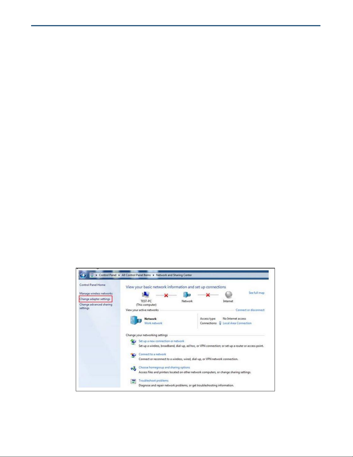
1. Click Start >Control Panel > Network and Internet >View network status and tasks.
2. In the left pane, click Change adapter settings.
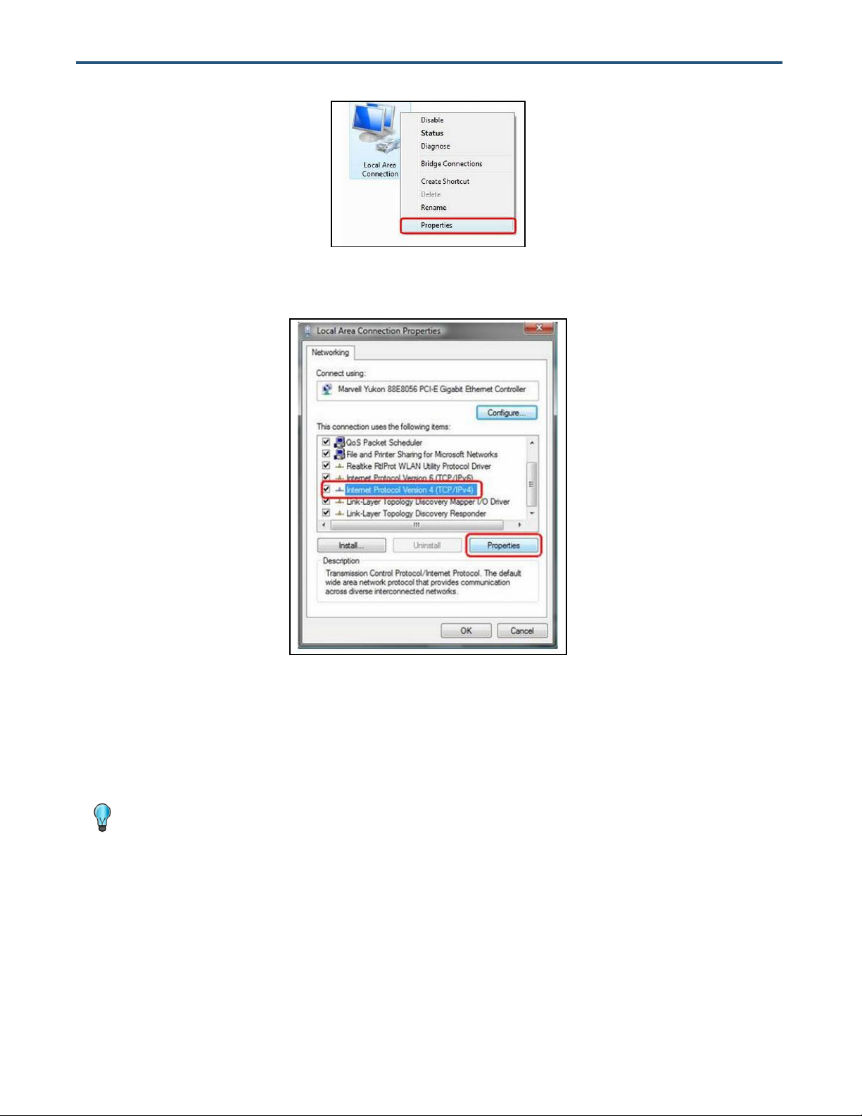
3. On the right side of the page, select the connection, right click it, and then select Properties.
20
EX17908 Web-Smart Switch User Guide
Page 21
Tip: Although the last digit in the previous step is 10, in reality, this digit can be any number
between 0 and 255, except the number 1 because the address 192.168.2.1 is already being
used by the switch.
4. Click Internet Protocol Version 4 (TCP/IPv4), and then click Properties.
5. In the General tab, click Use the following IP address.
6. In the IP address field, type 192.168.2.10.
7. Press the Tab key to populate the Subnet mask field automatically. You can leave the Default
gateway field blank.
21
EX17908 Web-Smart Switch User Guide
Page 22
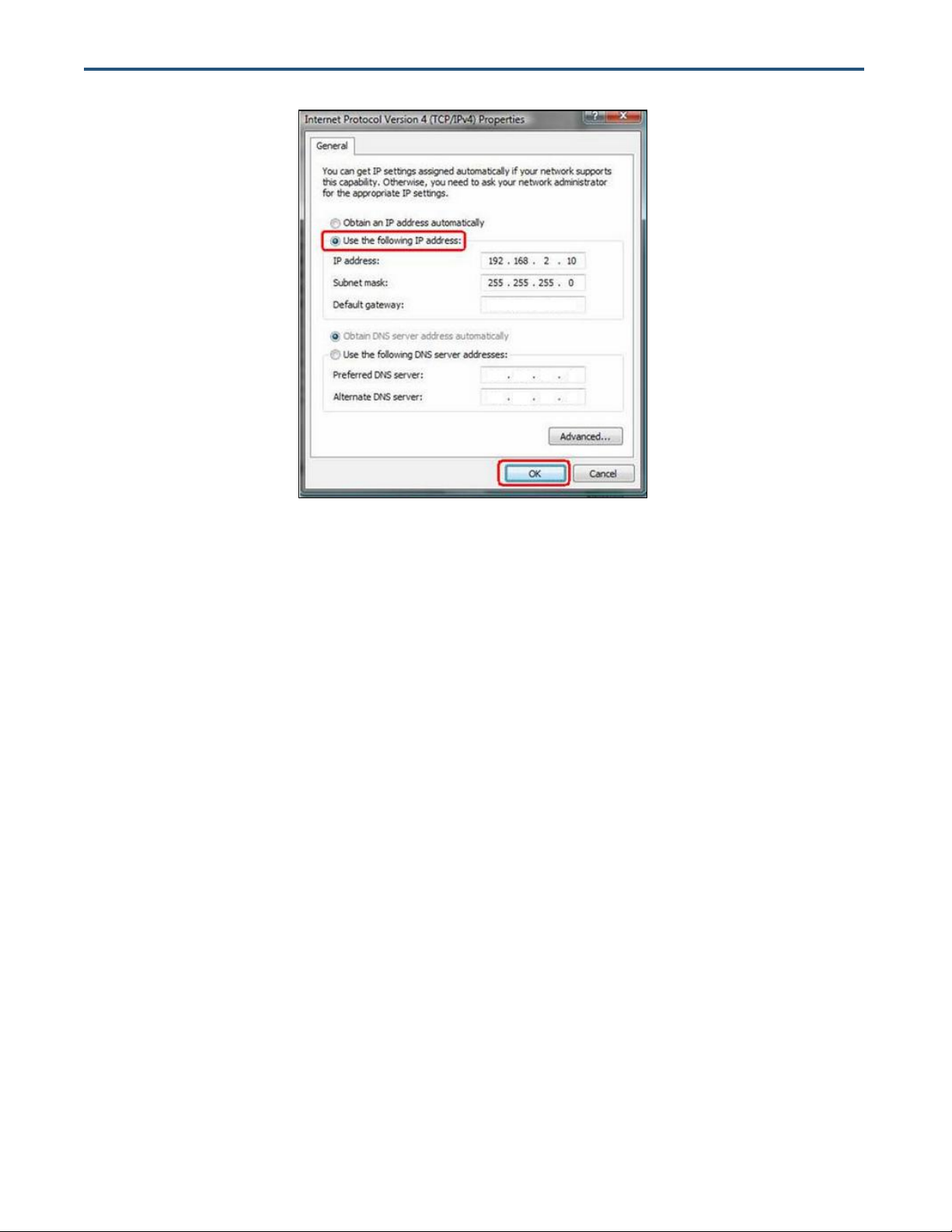
8. Click OK to exit the current dialog box, and then click OK again to exit the initial dialog box.
Disabling Proxy Settings
Before using the switch’s Web management interface, disable proxy settings in your Web browser.
Otherwise, you might not be able to view the switch’s Web-based configuration pages.
Disabling Proxy Settings in Internet Explorer
The following procedure describes how to disable proxy settings in Internet Explorer 5 and later.
1. Start Internet Explorer.
2. On your browser’s Tool menu, click Options. The Internet Options dialog box appears.
3. In the Internet Options dialog box, click the Connections tab.
4. In the Connections tab, click the LAN settings button. The Local Area Network (LAN) Settings
dialog box appears.
5. In the Local Area Network (LAN) Settings dialog box, uncheck all check boxes.
6. Click OK until the Internet Options window appears.
7. In the Internet Options window, under Temporary Internet Files, click Settings.
22
EX17908 Web-Smart Switch User Guide
Page 23

8. For the option Check for newer versions of stored pages, select Every time I visit the webpage.
9. Click OK until you close all open browser dialog boxes.
Disabling Proxy Settings in Firefox
The following procedure describes how to disable proxy settings in Firefox.
1. Start Firefox.
2. On your browser’s Tools menu, click Options. The Options dialog box appears.
3. Click the Advanced tab.
4. In the Advanced tab, click the Network tab.
5. Click the Settings button.
6. Click Direct connection to the Internet.
7. Click the OK button to confirm this change.
Disabling Proxy Settings in Safari
The following procedure describes how to disable proxy settings in Safari.
1. Start Safari.
2. Click the Safari menu and select Preferences.
3. Click the Advanced tab.
4. In the Advanced tab, click the Change Settings button.
5. Choose your location from the Location list (this is generally Automatic).
6. Select your connection method. If using a wired connection, select Built-in Ethernet. For wireless,
select Airport.
7. Click the Proxies tab.
8. Be sure each proxy in the list is unchecked.
9. Click Apply Now to finish.
23
EX17908 Web-Smart Switch User Guide
Page 24

Disabling Firewall and Security Software
If you encounter problems connecting to the switch, disable any firewall or security software that may
be running on your PC before configuring the switch. For more information, refer to the documentation
for your firewall.
24
EX17908 Web-Smart Switch User Guide
Page 25

Topics:
After you attach a PC to the switch and configure the PC to
the same subnet as the switch, use the information in this
chapter to configure the switch.
Logging in to the Web
Management Interface
(page 26)
Inactivity Timeout (page
27)
Understanding the Web
Management Interface
(page 27)
Web Management
Interface Menus (page
28)
4 Configuring the Switch
EX17908 Web-Smart Switch User Guide
25
Page 26

Note: Your computer does not have to be online to configure your switch.
Logging in to the Web Management Interface
To access the switch’s configuration settings, launch a Web browser on the PC you
configured in Chapter 3 and log in to the switch’s Web management interface.
1. Launch a Web browser.
2. In the browser address bar, type the switch’s default TCP/IP address of http://192.168.2.1:
3. Press the Enter key. The password screen appears (see Figure 4-1).
Figure 4-1. Password Screen
4. In the Password field, type admin as the default password. The password is case
sensitive.
5. Click Apply. The message Password Successfully Entered appears and the Web
management interface starts.
26
EX17908 Web-Smart Switch User Guide
Page 27

Note: First-time logins must set the switch’s DHCP setting (see page 33), default username,
and default password (see page 30).
Menus and
Submenus
Workspace
Inactivity Timeout
For security, the switch has an inactivity timeout feature that closes the current Web
management session automatically if the interface is not used for 60 seconds. This feature
prevents a session from remaining open to unauthorized users if the operator should walk
away from the management PC. You can change this default value using the Inactivity
Timeout setting on the Configuration > System page (see “System Configuration Page” on
page 30).
Understanding the Web Management Interface
The left side of the Web management interface contains the menus and submenus you use
to configure the switch. When you click a submenu, the configuration settings associated with
the menu appear in the workspace (see Figure 4-2).
Figure 4-2. Main Areas on the Web Management Interface
27
EX17908 Web-Smart Switch User Guide
Page 28

Table 4-1. Web Management Interface Menus and Submenus
Menus and Submenus
Description
See Page
Configuration > System
Sets the switch’s system configuration parameters.
30
Configuration > Ports
Enables jumbo frames, shows the link status of the switch ports, and configures the
switch port mode and flow control settings.
33
Configuration > VLANs
Adds, modifies, deletes virtual LANs (VLANs), and configures VLAN port settings.
37
Configuration > Aggregation
Configures trunk ports.
42
Configuration > RSTP
Configures Rapid Spanning Tree Protocol (RSTP) settings.
43
Configuration > IGMP Snooping
Configures Internet Group Management Protocol ( (IGMP) snooping settings.
45
Configuration > Mirroring
Configures port mirroring settings.
47
Configuration > Quality of Service
Configures Quality of Service (QoS) settings.
48
Configuration > Power over Ethernet
Configures Power over Ethernet settings.
50
Configuration > Storm Control
Configures settings for avoiding broadcast storms on the network.
51
Monitoring > Statistics Overview
Shows port, along with transmit and receive frames, bytes, and errors.
54
Monitoring > Detailed Statistics
Shows detailed statistics for each switch port.
55
Monitoring > RSTP Status
Shows RSTP VLAN bridge and RSTP port status information.
56
Monitoring > IGMP Status
Shows IGMP status information.
57
Monitoring > Ping
Checks connectivity between the switch and another device.
58
Maintenance > Warm Restart
Restarts the switch.
60
Maintenance > Factory Default
Returns the switch to factory default settings.
61
Maintenance > Software Upload
Updates the switch firmware.
62
Maintenance > Configuration File Transfer
Uploads or downloads configuration files.
63
Maintenance > Logout
Logs you out of the current Web management interface session.
Web Management Interface Menus
Table 4-1 describes the pages in the Web management interface. The first time you configure
the switch, you must configure the following settings on the Configuration > System page:
DHCP Enabled to specify whether the switch will receive an IP address allocated
dynamically by a DHCP server located on the network.
Name to change the default username.
Password to change the default password used to log in to the Web management
interface.
EX17908 Web-Smart Switch User Guide
28
Page 29

System changes the system configuration
settings, including the DHCP setting, and the default
username and password used to log in to the Web
management interface. See page 30.
Ports enables jumbo frames, power saving mode,
and port settings. See page 33.
VLANs adds, modifies, and deletes virtual Local
Area Network (VLAN) settings. See page 37.
Aggregation bundles switch port. See page 42.
RSTP configures RSTP system and port
configuration settings. See page 43.
IGMP Snooping configures IGMP settings. See
page 45.
Mirroring configures mirroring and mirror port
settings. See page 47.
Quality of Service enables or disables QoS
settings. See page 48.
Power over Ethernet configures PoE settings.
See page 50.
Storm Control configures the number of frames
transmitted per second . See page 51.
Configuration Menu
The Configuration menu lets you perform the following tasks:
EX17908 Web-Smart Switch User Guide
29
Page 30

System Configuration Page
Path: Configuration > System
The System Configuration page is organized into two areas:
The top area contains read-only fields that show the switch’s current configuration
settings.
The bottom area lets you change the switch’s configuration settings.
30
EX17908 Web-Smart Switch User Guide
Page 31

Field
Description
MAC Address
Switch’s unique Media Access Channel (MAC) address assigned by the manufacturer.
S/W Version
Version of the firmware running on the switch.
H/W Version
Version of switch hardware.
Active IP Address
Current static IP address assigned to the switch.
Active Subnet Mask
Current subnet mask assigned to the switch.
Active Gateway
Current gateway setting assigned to the switch.
DHCP Server
Current IP address assigned to the switch by a DHCP server.
Lease Time Left
Amount of time that a network device is allowed connection to the switch using its current dynamic IP address.
When this lease time expires, the device is assigned a new dynamic IP address automatically.
Field
Description
Default
DHCP Enabled
If your network has a DHCP server to allocate IP addresses dynamically, check this
check box. Otherwise, leave this check box unchecked to configure the switch for a
static IP address, and then complete the Fallback IP Address, Fallback Subnet
Mask, and Fallback Gateway settings.
Not Checked
Fallback IP Address
If DHCP Enabled is unchecked, enter a static IP address for the switch using the
format 00.00.00.00.
192.168.2.1
Fallback Subnet Mask
If DHCP Enabled is unchecked, enter a subnet mask using the format 00.00.00.00..
255.255.255.0
Fallback Gateway
If DHCP Enabled is unchecked, enter a gateway for the switch using the format
00.00.00.00..
192.168.2.254
Management VLAN
ID of a configured VLAN (1-4096) through which you can manage the switch. By
default, all ports on the switch are members of VLAN 1. However, if the
management VLAN is changed, the management station must be attached to a port
belonging to this VLAN.
1
Name
Case-sensitive username.
admin
The first time you log in, we recommend you:
Confirm the DHCP setting
Change the default username and password used to log in to the switch’s Web
management interface to prevent unauthorized individuals from gaining access to the
switch.
System Configuration Read-Only Fields
The following read-only fields appear under System Configuration.
System Configuration
Use the following fields under System Configuration to configure the switch.
31
EX17908 Web-Smart Switch User Guide
Page 32

Field
Description
Default
Password
Case-sensitive password used to log in to the Web management interface
admin
Inactivity Timeout
Number of minutes a Web management session can be idle before the switch ends
the session. Range: 60 – 10000 seconds.
60
SNMP enabled
Enables or disables the switch’s Simple Network Management Protocol (SNMP)
capabilities. The switch supports SNMP version 1 and 2c management clients.
Checked = enable SNMP. Complete the fields below.
Unchecked = disable SNMP.
Checked
SNMP Trap
destination
IP address of the destination for receiving SNMP traps.
0.0.0.0
SNMP Read
Community
Read-only community string. Enables requests accompanied by this string to
display MIB-object information.
public
SNMP Write
Community
Read/Write. Enables requests accompanied by this string to display MIB-object
information and set MIB objects.
private
SNMP Trap
Community
Enables requests accompanied by this string to receive SNMP traps.
public
EX17908 Web-Smart Switch User Guide
32
Page 33

Port Configuration Page
Path: Configuration > Ports
The Port Configuration page lets you enable jumbo frames, configure power saving mode,
and view the switch port status and configure port modes.
33
EX17908 Web-Smart Switch User Guide
Page 34

Jumbo Frames
Power Saving Mode
The switch provides efficient large sequential data transfers by supporting jumbo frames up
to 9000 bytes. Compared to standard Ethernet frames that run up to 1500 bytes, using jumbo
frames significantly reduces the per-packet overhead required to process protocol
encapsulation fields, reduce processing time, and increase transfer performance.
By default, jumbo frames are enabled on the switch. To use jumbo frames, both the source
and destination end nodes (such as a computer or server) must support jumbo frames. In
addition, when the connection operates at full-duplex, all switches in the network between the
two end nodes must be able to accept the extended frame size. For half-duplex connections,
all devices in the collision domain must support jumbo frames.
To disable jumbo frames, uncheck Enable Jumbo Frames.
By default, the switch is configured for full power saving mode. This mode automatically
adjusts the power provided to ports. The following power saving mode selections are
available:
Choices are:
Full = activate maximum power saving mode. This is the default setting.
Link-up = save power when the switch port link is up (operational).
Link-down = save power when the switch port link is down (non-operational).
Disable = deactivate power saving mode.
34
EX17908 Web-Smart Switch User Guide
Page 35

Port Settings
Field
Description
Port
Number corresponding to each port on the switch.
Link
Read-only fields that show whether the switch ports are up or down.
Up ports are color-coded green and show the speed of the connection. In the example above, port 4 is
operating at 1000 Mbps full-duplex.
Down ports are color-coded red.
Mode
Configures the negotiation mode for the switch port. Choices are:
Auto Speed = port adjusts automatically to the speed and duplex setting of the device connecting to this port.
(default)
10 Half = port is configured for 10 Mbps half-duplex transmission only.
10 Full = port is configured for 10 Mbps full-duplex transmission only.
100 Half = port is configured for 100 Mbps half-duplex transmission only.
100 Full = port is configured for 100 Mbps full-duplex transmission only.
1000 Half = port is configured for 1000 Mbps half-duplex transmission only.
1000 Full = port is configured for 1000 Mbps full-duplex transmission only.
Disabled = port is out of action and not operational.
Flow Control
Enables or disables flow control for each port.
Check = enable flow control. Flow control handles situations where a transmitting computer is sending data
faster than a receiving machine can handle it. The IEEE 802.3x standard specifies a PAUSE flow control
mechanism communicated via MAC Control frames in full duplex Ethernet link segments. Like jumbo frames,
the PAUSE mechanism requires all device in the data flow path to support it. By default, flow control is
enabled on all switch ports. In small networks, however, you may want to disable flow control if you experience
throughput loss or low performance.
Uncheck = disable flow control.
The port settings appear in the center of the Port Configuration page. Each row of the page
corresponds to one port. The following table describes the port settings.
35
EX17908 Web-Smart Switch User Guide
Page 36

Drop Frames After
Excessive Collisions
Apply and Refresh Buttons
When the Drop frames after excessive collisions check box is checked, the switch drops
frames after an excessive number of collisions. By default, this check box is checked.
If you change any settings on the Port Configuration page, click Apply to apply the changes.
Clicking the Refresh button updates the screen with the latest status.
36
EX17908 Web-Smart Switch User Guide
Page 37

Port Segmentation (VLAN) Configuration
Path: Configuration > VLANs
The switch supports up to 16 VLANs based on the 802.1Q standard. From the Port
Segmentation (VLAN) Configuration page, you can create and delete VLANs, and change
the VLAN port membership.
The Add a VLAN area lets you add a VLAN. The VLAN Configuration List shows the
VLANs that have been configured. Buttons below the list let you modify, delete, or refresh the
VLAN information shown.
A Port Config button lets you configure the VLAN ports.
Adding a VLAN
To add a VLAN:
1. Under Add a VLAN, click in the VLAN ID field and enter an ID for the new VLAN.
2. Click Add. The VLAN Setup page appears, listing the switch’s eight ports.
37
EX17908 Web-Smart Switch User Guide
Page 38

Example of two VLANs,
with VLAN 1 selected
3. By default, all switch ports are members of the VLAN. To exclude a port from this VLAN,
uncheck the Member check box for the port.
4. Click Apply. The Port Segmentation (VLAN) Configuration page reappears, with the VLAN
you configured shows below VLAN Configuration List.
5. To configure additional VLANs, repeat steps 1 through 4.
The following example shows a switch that has two VLANs.
38
EX17908 Web-Smart Switch User Guide
Page 39

Note: A warning message does not appear when you click Delete. Therefore, be sure you
want to delete the VLAN before clicking Delete.
Modifying a VLAN
There may be times when you need to modify the port membership in a VLAN.
To modify a VLAN:
1. Under VLAN Configuration List, click the ID of the VLAN you want to edit.
2. Click Modify. The VLAN Setup page appears, with the settings for the VLAN you selected.
3. Change the VLAN settings as desired, and then click Apply.
Deleting a VLAN
If you no longer need a VLAN, you can delete it.
To delete a VLAN:
1. Under VLAN Configuration List, click the ID of the VLAN you want to delete.
2. Click Delete to delete the VLAN
Configuring VLAN Ports
The Port Config button on the Port Segmentation (VLAN) Configuration page lets you
change the VLAN parameters for individual ports or trunks. You can configure VLAN
behavior for specific interfaces, including the accepted frame types and default VLAN
identifier (PVID). Each row of the page corresponds to one port.
To configure VLAN ports:
1. Click the Port Config button. The VLAN Per Port Configuration page appears.
39
EX17908 Web-Smart Switch User Guide
Page 40

Field
Description
Port
Number corresponding to each port on the switch.
VLAN aware Enabled
Enables or disables VLAN awareness for each port.
Checked = makes the port VLAN-aware. VLAN aware ports use VLAN-tagged frames to determine the
destination VLAN of a frame. VLAN-aware ports strip the VLAN tag from received frames and insert the tag
into transmitted frames (except for the PVID).
Unchecked = makes the port VLAN-unaware. VLAN unaware ports do not strip the tag from received frames
or insert the tag into transmitted frames.
Ingress Filtering
Enabled
Enables or disables ingress filtering for each port.
Checked = enable ingress filtering. The switch discards incoming frames for VLANs that do not include this
ingress port in their member set.
Unchecked = disables ingress filtering.
Packet Type
Sets the interface to accept all frame types, including tagged or untagged frames, or only tagged frames. Choices
are:
All = port can accept incoming tagged and untagged packets. Any received packets that are untagged are
assigned to the default VLAN. Any tagged packets are dropped, unless the port is a member of the VLAN
identified by the VLAN tag in the packet.
Tagged Only = port drops untagged packets and receives tagged packets only. Tagged packets are dropped,
unless the port is a member of the VLAN identified by the VLAN tag in the packet. Switches should be
connected to each other with the Packet Type set to Tagged Only.
2. Complete the settings in the page, and then click Apply.
EX17908 Web-Smart Switch User Guide
40
Page 41

Field
Description
Pvid
The PVID (Port VLAN ID) is associated with untagged, ingress packets and assigned to untagged frames
received on the specified interface. The PVID has no effect on ports whose Packet Type is set to “Tagged Only.”
You cannot remove a port from VLAN 1, unless its PVID is changed to a value other than 1. Outgoing packets are
tagged unless the packet’s VLAN ID is the same as the PVID.
If the PVID is set to “None”, all outgoing packets are tagged.
If you select “Tagged Only” mode for a port, we recommend setting the PVID to “None” as the standard
configuration.
EX17908 Web-Smart Switch User Guide
41
Page 42

Aggregation/Trunking Page
Path: Configuration > Aggregation
The Aggregation/Trunking Configuration page lets you bundle (or aggregate”) multiple links
together to act as a single physical link for increased throughput. Bundling links provides load
balancing and redundancy of links in a switched inter-network.
In reality, the link does not have an inherent total bandwidth equal to the sum of its
component physical links. Traffic in a trunk is distributed across an individual link within the
trunk in a deterministic method using a hash algorithm. The hash algorithm applies load
balancing to the ports in the trunk automatically. A port failure within the trunk group redirects
network traffic to the remaining ports. Load balancing is maintained whenever a link in a trunk
is lost or returned to service.
You can configure up to four trunks. To assign ports to a trunk:
1. On the Group 1 row, click the trunk numbers you want to aggregate.
2. Click Apply.
3. To configure up to three additional trunks, repeat steps 1 and 2 on the next Group row.
42
EX17908 Web-Smart Switch User Guide
Page 43

RSTP System Configuration Page
Path: Configuration > RSTP
For optimal performance, there should be a single active path between two networking
devices in an Ethernet network. Rapid Spanning Tree Protocol (RSTP) provides redundant
paths and prevents network loops that can create excessive traffic and slow down
performance. RSTP calculates the best path for network traffic; if the best path fails, RSTP
recalculates and finds the next best path
The RSTP Configuration page lets you configure the switch’s RSTP settings.
The top area lets you specify the switch’s RSTP system configuration settings.
The bottom area lets you specify the switch’s RSTP port configuration settings.
43
EX17908 Web-Smart Switch User Guide
Page 44

Field
Description
Default
System Priority
Identifies the root bridge. The bridge with the lowest value has the highest priority and is selected as
the root. If the value has been changed, user has to reboot the switch. The value must be multiple of
4096 according to the protocol standard rule
32768
Hello Time
Interval, in seconds, that determines how often the switch broadcasts hello messages to other
switches. Range: 1 – 10 seconds.
2
Max Age
Amount of time, in seconds, that protocol information received on a port is stored by the switch.
Range: 6 – 40 seconds.
20
Forward Delay
Number of seconds that determines how long each of the listening and learning states lasts before the
port begins forwarding. Range: 4 – 30 seconds.
15
Force version
Select the RSTP default protocol. Choices are:
Normal = RSTP protocol.
Compatible = compatible with STP protocol
Normal
Field
Description
Default
Protocol Enabled
Enables or disables the RSTP protocol for the port.
Unchecked
Edge
Check to set the port as an edge port. An edge port prevents directly connected to end stations from
creating a bridging loop in the network.
Checked
Path Cost
Used by the STP to determine the best path between devices. Assign low values to ports attached to
fast media, and assign high values assigned to ports with slow media. Range: 1 - 200,000,000. 0 =
auto generated path cost.
auto
RSTP System Configuration
RSTP Port Configuration
44
EX17908 Web-Smart Switch User Guide
Page 45

Field
Description
Default
IGMP Enabled
Enables or disables IGMP functions.
Checked = enable IGMP functions. Configure the settings below.
Unchecked = disable IGMP functions.
Unchecked
Router Ports
Check the check boxes beside the port number.
Unchecked
Unregistered IPMC
Flooding enabled
Set the forwarding mode for unregistered (not-joined) IP multicast traffic. The traffic will flood when
enabled, and forward to router-ports only when disabled.
Checked
IGMP Snooping
Enabled
Enables or disables IGMP snooping.
Checked = port monitors network traffic to determine which hosts want to receive the multicast
traffic.
Unchecked = port does not monitor network traffic.
Checked
IGMP Configuration Page
Path: Configuration > IGMP
The IGMP Configuration page lets you configure the switch’s Internet Group Management
Protocol (IGMP) settings. IGMP allows the switch to “listen in” on IGMP conversations
between hosts and routers by processing Layer 3 IGMP packets sent in a multicast network.
When IGMP is enabled, the switch analyzes all IGMP packets between hosts connected to
the switch and multicast routers in the network.
When the switch hears an IGMP report from a host for a given multicast group, the switch
adds the host’s port number to the multicast list for that group.
When the switch hears an IGMP Leave, it removes the host’s port from the table entry.
If you change the settings on this page, click Apply to apply your settings. A Refresh button
lets you update the information on the screen.
EX17908 Web-Smart Switch User Guide
45
Page 46

Field
Description
Default
IGMP Querying
Enabled
Enables or disables IGMP querying.
Checked = port can serve as the Querier, which is responsible for asking hosts if they want to
receive multicast traffic.
Unchecked = port cannot serve as the Querier.
Checked
EX17908 Web-Smart Switch User Guide
46
Page 47

Field
Description
Default
Port
Number corresponding to each port on the switch.
Mirror Source
Check the ports that you want to mirror.
Unchecked
Mirror Port
Port that will duplicate (or “mirror”) the traffic on the source port. Only incoming packets can be
mirrored. Packets are dropped when the available egress bandwidth is less than ingress bandwidth.
1
Mirroring Configuration Page
Path: Configuration > Mirroring
The Mirroring Configuration page lets you configure the switch’s port mirroring settings. Port
mirroring is used on a network switch to send a copy of network packets seen on one switch
port (or an entire VLAN) to a network monitoring connection on another switch port. This
feature is commonly used for network appliances that require monitoring of network traffic,
such as an intrusion-detection system.
If you change the settings on this page, click Apply to apply your settings. A Refresh button
lets you update the information on the screen.
47
EX17908 Web-Smart Switch User Guide
Page 48

Field
Description
Default
Queue Mode
Selects the QoS configuration. Choices are:
Strict = services the egress queues in sequential order, transmitting all traffic in the higher priority
queues before servicing lower priority queues.
WRR = Weighted Round-Robin shares bandwidth at the egress ports by using scheduling weights
with default values of 1, 2, 4, 8 for queues 0 through 7, respectively. WRR can be selected only if
Enable Jumbo Frame is unchecked on the Port Configuration page (see page 33).
Strict
QoS Mode
Selects the QoS mode. Choices are:
QoS Disabled = disable QoS.
802.1p = prioritizes packets using the 802.1p field in the VLAN tag. This field is three bits long,
representing the values 0 - 7. If you click this option, the 802.1p configuration table in Figure 4-3
lets you map each of the eight 802.1p values to a local priority queue (low, normal, medium or
high).
DSCP = prioritizes packets using the Differentiated Services Code Point (DSCP) value. The DSCP
is a 6-bit field contained in an IP (TCP or UDP) header. The six bits allow the DSCP field to take
any value in the range 0 - 63. When QoS Mode is set to DSCP, the DSCP configuration table in
Figure 4-4 lets you map each of the DSCP values to a hardware output queue (low, normal,
medium or high). The default settings map all DSCP values to the high priority egress queue.
QoS Disabled
QoS Configuration Page
Path: Configuration > Quality of Service
The QoS Configuration page lets you configure the switch to deliver better resource
reservation control.
If you change the settings on this page, click Apply to apply your settings. A Refresh button
lets you update the information on the screen.
EX17908 Web-Smart Switch User Guide
48
Page 49

Figure 4-3. QoS Configuration Page when QoS Mode is Set to 802.1p
Figure 4-4. QoS Configuration Page when QoS Mode is Set to DSCP
49
EX17908 Web-Smart Switch User Guide
Page 50

Field
Description
Default
Port
Number corresponding to each port on the switch.
PoE Enabled
Enables or disables PoE on the port.
Checked = enable PoE on the port.
Unchecked = disable PoE on the port.
Checked
PD Class
Read-only field that shows the class of PD detected.
Delivering Power
Read-only field that shows the amount of power being delivered to the device, in Watts.
Current
Read-only field that shows the amount of current being delivered to the device, in Milliamperes.
Voltage
Read-only field that shows the amount of voltage being delivered to the device, in Volts.
Power Budget
Read-only field that shows the total PoE power per port.
PoE (Power over Ethernet) Configuration Page
Path: Configuration > Power over Ethernet
Power over Ethernet (PoE) is a mechanism for supplying power to network devices over the
same cabling used to carry network traffic. PoE allows devices that require power, called
Powered Devices (PDs), to receive power and data over existing infrastructure without
having to upgrade the infrastructure.
The PoE (Power over Ethernet) Configuration page lets you enable PoE on a per-port basis.
If you change the settings on this page, click Apply to apply your settings. A Refresh button
lets you update the information on the screen.
50
EX17908 Web-Smart Switch User Guide
Page 51

Storm Control Configuration Page
Path: Configuration > Storm Control
Broadcast storms can occur when a device on your network malfunctions, or if application
programs are not well designed or properly configured. If there is too much broadcast traffic
on your network, performance can be degraded severely or all traffic can come to complete
halt.
To protect your network from broadcast storms, use the Storm Control Configuration page to
set a threshold for broadcast traffic for all ports. This page lets you limit the rate on three
types of traffic:
Broadcast frames
Multicast frames
Flooded unicast rate frames
Each frame type has a drop-down list that lets you select a threshold. Any broadcast packets
that exceed the specified threshold are dropped. The default setting of No Limit does not
enforce storm control.
If you change the settings on this page, click Apply to apply your settings. A Refresh button
lets you update the information on the screen.
51
EX17908 Web-Smart Switch User Guide
Page 52

52
EX17908 Web-Smart Switch User Guide
Page 53

Statistics Overview provides a statistical overview of
each switch port. See page 54.
Detailed Statistics copies network traffic from one
port to another port. See page 55.
RSTP Status limits the rates at which the switch
accepts incoming data and retransmits outgoing data.
See page 56.
IGMP Status prevents LAN traffic from being disrupted
by a broadcast, multicast, or unicast storm on a port. See
page 57.
Ping enables or disables PoE on switch ports. See
page 58.
Monitoring Menu
The Monitoring menu lets you perform the following tasks:
53
EX17908 Web-Smart Switch User Guide
Page 54

Statistics Overview Page
Path: Monitoring > Statistics Overview
The Statistics Overview page is a read-only page that shows the following information for
each switch port:
Transmitted bytes
Transmitted frames
Received bytes
Received frames
Transmit errors
Receive errors
A Clear button lets you clear the information shown and a Refresh button lets you update the
information shown.
54
EX17908 Web-Smart Switch User Guide
Page 55

Detailed Statistics Page
Path: Monitoring > Detailed Statistics
The Detailed Statistics page is a read-only page that shows detailed port information
arranged in the following categories:
Receive total
Receive size counters
Receive error counters
Transmit total
Transmit size counters
Transmit error counters
Buttons are provided for selecting the port whose detailed statistics you want to view. A Clear
button lets you clear the information shown and a Refresh button lets you update the
information shown.
55
EX17908 Web-Smart Switch User Guide
Page 56

Field
Description
VLAN Id
VLAN identifier.
Bridge Id
Unique identifier for the switch in the Spanning Tree.
Hello Time
Time interval, in seconds, at which the root device transmits a configuration message.
Max Age
Maximum time, in seconds, that the switch waits before attempting to reconfigure if it has not received a
configuration message.
Fwd Delay
Maximum time, in seconds, the root device waits before changing states from listening to learning to forwarding.
Topology
Indicates whether spanning tree topology is steady or undergoing reconfiguration. (The time required for
reconfiguration is extremely short, so no values other that “steady” state are likely to be seen in this field.)
Root Id
Priority and MAC address of the device in the Spanning Tree that this switch has accepted as the root device, and
the port connected to the root device.
RSTP VLAN Bridge Overview Page
Path: Monitoring > RSTP Status
The RSTP VLAN Bridge Overview page is a read-only page that shows the switch’s Rapid
Spanning Tree Protocol information.
56
EX17908 Web-Smart Switch User Guide
Page 57

Field
Description
VLAN ID
VLAN identifier.
Querier
Shows whether Querying is enabled.
Queries transmitted
Number of transmitted Query packets.
Queries received
Number of received Query packets.
v1 reports
Number of received v1 Report packets.
v2 reports
Number of received v2 Report packets.
v3 reports
Number of received v3 Report packets.
v2 Leaves
Number of v2 leave packets received.
IGMP Status Page
Path: Monitoring > IGMP Status
The IGMP Status page is a read-only page that shows the switch’s IGMP snooping statistics.
57
EX17908 Web-Smart Switch User Guide
Page 58

Field
Description
Target IP address
IP address you entered for the switch to contact.
Status
Status of the ping operation.
Received replies
Number of replies received from the ping.
Request timeouts
Number of request timeouts experienced during the ping.
Average Response Time
Average response time, in milliseconds, when the target device replied to the switch pings.
Ping Parameters Page
Path: Monitoring > Ping
The Ping Parameters page lets you check connectivity between the switch and devices on
the network.
.
To perform a ping:
1. In the Target IP address field, enter the IP address you want the switch to contact.
2. In the Count field, enter the number of packets you want the switch to send. Range: 1 – 20.
3. In the Time Out field, enter the number of seconds that the switch should ping the target IP
address.
4. Click Apply. The results of the ping appear under Ping Results.
EX17908 Web-Smart Switch User Guide
58
Page 59

Warm Restart restarts the switch. See page 60.
Factory Default returns the switch to factory default
settings. See page 61.
Software Upload updates switch firmware. See page 62.
Configuration File Transfer uploads and downloads
configuration files. See page 63.
Logout ends the current Web management interface
session.
Maintenance Menu
The Maintenance menu lets you perform the following tasks:
59
EX17908 Web-Smart Switch User Guide
Page 60

Warm Restart Page
Path: Maintenance > Warm Restart
The Warm Restart page lets you restart the switch. Any changes you made to the switch’s
factory default configuration are maintained after the warm start.
60
EX17908 Web-Smart Switch User Guide
Page 61

Factory Default Page
Path: Maintenance > Factory Default
The Factory Default page lets you restart the switch and return it to its factory default settings.
Any changes you made to the switch’s factory default configuration will be discarded after the
reboot.
61
EX17908 Web-Smart Switch User Guide
Page 62

Software Upload Page
Path: Maintenance > Software Upload
The Software Upload page lets you upgrade the switch firmware.
1. Download the switch firmware.
2. At the Software Upload page, click the Browse button.
3. In the Choose File to Upload dialog box, go to the location where the firmware file is located,
and then click the file and click Open.
4. Click Upload to load the new firmware.
62
EX17908 Web-Smart Switch User Guide
Page 63

Configuration Upload Page
Path: Maintenance > Configuration File Transfer
The Configuration Upload page lets you lets you save the switch configuration on your
computer or restore the switch configuration by uploading a configuration file that you saved
previously on your computer.
To save the switch configuration:
1. Under Configuration Download, click Download.
2. When the File Download dialog box appears, click Save.
3. In the Save As dialog box, go to the location where you want to save the file, and then click
Save.
63
EX17908 Web-Smart Switch User Guide
Page 64

To recover switch settings using a configuration file you saved using the procedure above:
1. Under Configuration Upload, click Browse.
2. When the Choose File to Upload dialog box appears, use the dialog box to go to the
location where the bin file resides, and then click the file and click Open.
3. Click Upload.
64
EX17908 Web-Smart Switch User Guide
Page 65

Topics:
This chapter provides information about troubleshooting
the switch.
Troubleshooting Chart
(page 66)
Additional
Troubleshooting
Suggestions (page 67)
5 Troubleshooting
EX17908 Web-Smart Switch User Guide
65
Page 66

Symptom
Cause
Solution
Power LED is OFF.
The switch is not receiving
power.
Check the power cord connections for the switch at the switch and the
connected device.
Be sure all cables used are correct and comply with Ethernet
specifications.
Link/ACT LED is OFF or
intermittent.
Port connection is not
working.
Check the crimp on the connectors and be sure the plug is inserted
properly and locked into the port at both the switch and the connecting
device.
Be sure all cables used are correct and comply with Ethernet
specifications.
Check for a defective adapter card, cable, or port by testing them in an
alternate environment where all products are functioning.
File transfer is slow or
performance degradation
is a problem.
Half- or full-duplex setting on
the switch and the connected
device are not the same.
Configure the switch and the attached device to auto-negotiate.
A segment or device is
not recognized as part of
the network.
One or more devices are not
connected properly or cabling
does not meet Ethernet
guidelines.
Verify that the cabling is correct.
Be sure all connectors are securely positioned in the required ports.
Equipment may have been disconnected accidentally.
Collisions are occurring
on the connected
segment.
Some collisions are normal
when the connection is
operating in half-duplex
mode.
Recheck the settings of the device attached to the switch port.
Be sure the switch and the attached device are using the same duplex
setting.
Be sure the switch and the attached device are set to auto-negotiate.
Check and, if necessary, change the settings on the Configuration >
Storm Control page (see page 51).
Link/ACT LED is flashing
continuously on all
connected ports and the
network is disabled.
A network loop (redundant
path) has been created.
Use the RSTP System Configuration to use the Rapid Spanning Tree
Protocol to eliminate loops (see page 43).
Break the loop by ensuring that there is only one path from any networked
device to any other networked device.
Troubleshooting Chart
Table 5-1 symptoms, causes, and solutions of possible problems.
Table 5-1. Troubleshooting Chart
EX17908 Web-Smart Switch User Guide
66
Page 67

Additional Troubleshooting Suggestions
If the suggestions in Table 5-1 do not resolve your problem, refer to the troubleshooting
suggestions in this section.
Network Adapter Cards
Be sure the network adapter cards installed in the PC used to configure the switch are in
working condition and the latest software driver has been installed.
Configuration
If problems occur after altering the switch’s network configuration, restore the original
connections and determine the problem by implementing the new changes one step at a time.
Be sure cable distances, repeater limits, and other physical aspects of the installation do not
exceed the Ethernet limitations.
Switch Integrity
If required, verify the integrity of the switch by resetting it. To reset the switch, use the reset
button on the front panel (see “Reset Button” on page 12) or use the Maintenance > Warm
Restart page on the switch’s Web management interface (see “Warm Restart Page” on page
60). If the problem continues, contact EtherWAN Systems technical support.
Auto-Negotiation
The 10/100 Mbps ports negotiate the correct duplex mode and speed if the switch is
configured for auto-negotiation (this is the switch’s default setting) and the device at the other
end of the link supports auto-negotiation. If the device does not support auto-negotiation, the
switch determines only the speed correctly and the duplex mode defaults to half-duplex.
67
EX17908 Web-Smart Switch User Guide
Page 68

Specification
Description
Standards:
IEEE802.3, 10BASE-T
IEEE802.3u, 100BASE-TX
IEEE802.3ab, 1000BASE-T
IEEE802.3x,full-duplex and flow control
IEEE802.3at, Power over Ethernet (PoE)
Forward and Filtering
Rate:
10 Mbps: 14,880 pps
100 Mbps: 148,810 pps
1000 Mbps: 1,488,100 pps
Packet Buffer Memory:
2 M bits
Processing Type:
Store-and-Forward
Half-duplex back-pressure and IEEE802.3x full-duplex flow control
Jumbo Frame:
9.6 K bytes
Address Table Size:
8 K MAC addresses
Specification
Description
Power Input:
100 – 240 VAC, 50 / 60 Hz
Power Consumption:
Device: Max. 8.8 W (without PoE)
PoE power budget: 240 W Max.
PoE Power Output:
IEEE802.3af: up to 30 W/port, 55 VDC, 545 mA Max.
Technology
Appendix A - Specifications
Power
EX17908 Web-Smart Switch User Guide
68
Page 69

Specification
Description
Casing:
Metal case
Dimensions:
266 mm (W) x 160 mm (D) x 44 mm (H)
(10.47" (W) x 6.30" (D) x 1.73" (H))
Weight:
1.52 Kg (3.35 lbs)
Installation:
Desktop
Rack Mounting
Specification
Description
Ethernet Ports:
10/100/1000BASE-T: 8 ports (PoE)
LED Indicators:
Per unit: Power Status
Per port: Link/Activity, PoE Act/status
Specification
Description
Operating Temperature:
0°C to 40°C (32°F to 104°F)
Storage Temperature:
-10°C to 70°C (14°F to 158°F)
Ambient Relative
Humidity:
10% to 95% (non-condensing)
Specification
Description
ISO:
Manufactured in an ISO9001 facility
Emission Compliance:
FCC Part 15, Class A, CE mark Class A
Mechanical
Interface
Environment
Regulatory Approvals
69
EX17908 Web-Smart Switch User Guide
Page 70

70
EX17908 Web-Smart Switch User Guide
Page 71

Index
A
Adding a VLAN, 37
Aggregation, 42
Auto-negotiation, 66
B
Backup, 62
Broadcast storms, 51
C
Configuration
download, 62
upload, 62
Configuration menu, 29
Configuring VLAN ports, 39
Controlling storms, 51
D
Deleting a VLAN, 39
DHCP, 30
Disabling proxy settings, 22
Download configuration, 62
Drop Frames After Excessive Collisions, 36
Duplex settings, 35
Dynamic IP address, 30
F
Factory default, 60
Firmware, 61
Flow control, 35
I
IGMP, 45
status, 56
Inactivity timeout, 27
Internet Group Management Protocol, 45, 47
J
Jumbo frames, 30, 34
K
Key features, 8
M
Maintenance menu, 58
Menus
Configuration, 29
Maintenance, 58
Monitoring, 52
Mirroring, 47
Modifying a VLAN, 39
Monitoring menu, 52
N
Negotiation of ports, 35
P
Package contents, 11
Password, 30
Pinging, 57
PoE configuration, 50
Port negotiation, 35
Port settings, 35
Power over Ethernet configuration, 50
Power saving mode, 34
Proxy settings, disabling, 22
Q
QoS, 48
71
EX17908 Web-Smart Switch User Guide
Page 72

Quality of Service, 48
R
Rapid spanning tree protocol, 43
Recovery, 62
Reset button, 12
Restarting the switch
reset button, 12
Warm Restart page, 59
S
Spanning tree, 43
Specifications, 67
Speed settings, 35
Static IP address, 30
Statistics
detailed, 54
overview, 53
Storm control, 51
Switch
integrity, 66
key features, 8
package contents, 11
system requirements, 11
Switch restart
reset button, 12
Warm Restart page, 59
System requirements, 11
T
Timeout, 27
Troubleshooting
chart, 65
suggestions, 66
Trunking, 42
U
Unpacking, 11
Upload
configuration, 62
firmware, 61
Username, 30
V
VLAN
adding, 37
configuring ports, 39
deleting, 39
modifying, 39
W
Web management interface, 27
logging in, 26
menus
Configuration, 29
Maintenance, 58
Monitoring, 52
menus and submenus, 28
pages
Aggregation/Trunking, 42
Configuration Upload, 62
Detailed Statistics, 54
Factory Default, 60
IGMP Configuration, 45
IGMP Status, 56
Mirroring Configuration, 47
Ping Parameters, 57
PoE (Power over Ethernet) Configuration, 50
Port Configuration, 33
Port Segmentation (VLAN) Configuration, 37
QoS Configuration, 48
RSTP, 43
RSTP VLAN Brige Overview, 55
Software Upload, 61
Statistics Overview, 53
Storm Control, 51
System Configuration, 30
Warm Restart, 59
72
EX17908 Web-Smart Switch User Guide
Page 73

USA Office
4570 E. Eisenhower Circle
Anaheim, CA 92807
TEL: +1-714-779-3800
Email: info@etherwan.com
Pacific Rim Office
8F., No.2, Alley 6, Lane 235, Baoqiao Rd.,
Xindian District, New Taipei City 231,
Taiwan (R.O.C.)
TEL: +886 -2- 6629-8986
Email: info@etherwan.com.tw
EtherWAN System, Inc.
www.etherwan.com
EtherWAN has made a good faith effort to ensure the accuracy of the information in this document and disclaims
the implied warranties of merchantability and fitness for a particular purpose, and makes no express warranties,
except as may be stated in its written agreement with and for its customers.
EtherWAN shall not be held liable to anyone for any indirect, special or consequential damages due to omissions
or errors. The information and specifications in this document are subject to change without notice.
Copyright © 2014. All Rights Reserved.
All trademarks and registered trademarks are the property of their respective owners
EX17908 Web-Smart Switch User Guide
August 13, 2014
Document version: Version 1
 Loading...