

Page 1
Hardened Media Converter
V5 1
This quick start guide describes how to install and use the hardened media converter. This is the media converter of choice for harsh
environments constrained by space.
Physical Description
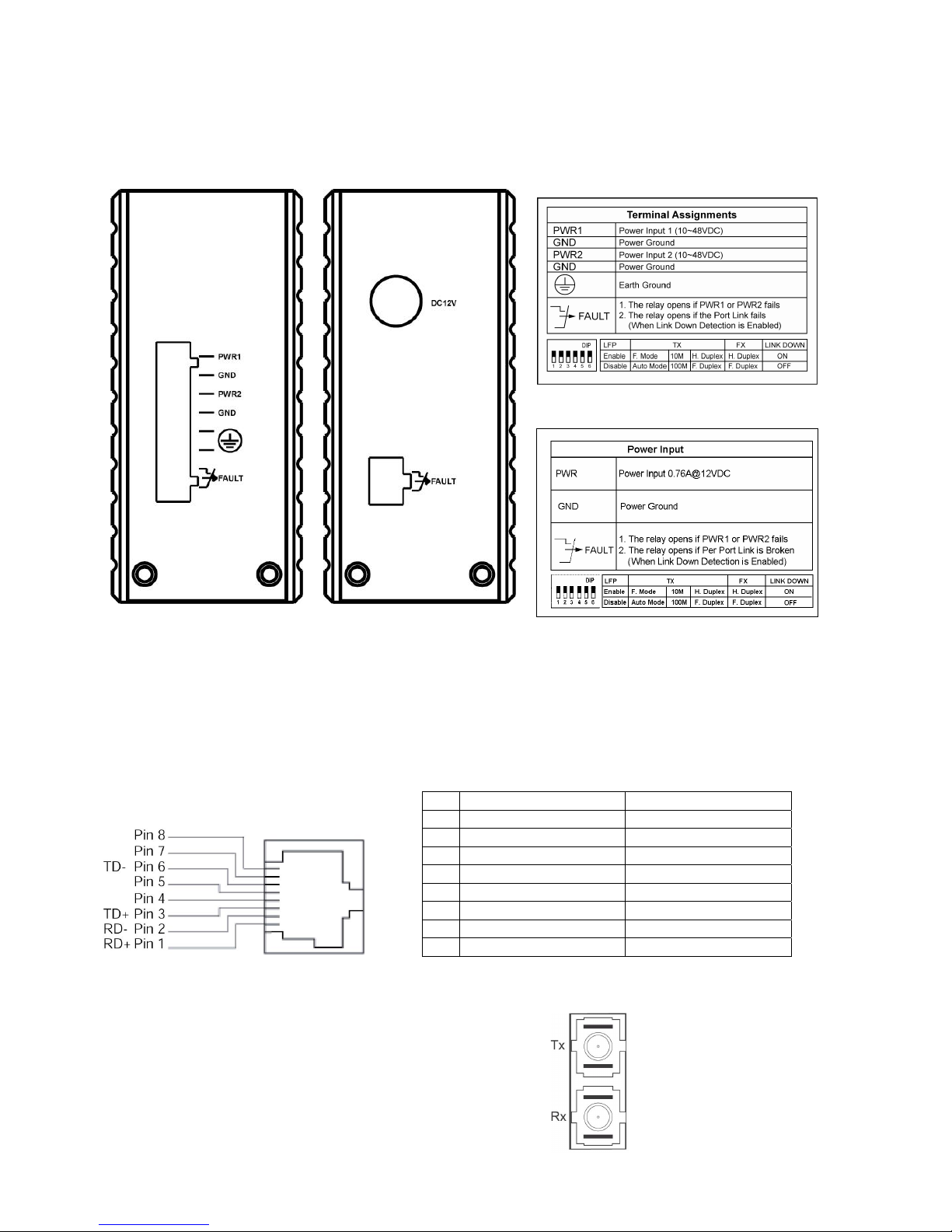
The Terminal Block and Power inputs
y DC Terminal Block Power Inputs: There are two pairs of power inputs can be used to power up this device. You need to have two power
inputs connected to run the media converter, but the FAULT LED indicator will light up to remind that the power redundant system
functions abnormal in case either PWR1 or PWR2 is dead. Media Converter, however, continues working normally even fault LED
indicator lights up.
• DC JACK Power input: 12VDC.
The 10/100Base-TX and 100Base-FX Connectors
The 10/100Base-TX Connections
The following lists the pinouts of 10/100Base-T/TX ports.
Pin Regular Ports Uplink port
1 Input Receive Data + Output Transmit Data +
2 Input Receive Data - Output Transmit Data -
3 Output Transmit Data + Input Receive Data +
4 NC NC
5 NC NC
6 Output Transmit Data - Input Receive Data -
7 NC NC
8 NC NC
The 100Base-FX Connections
The fiber port pinouts
The Tx (transmit) port of device I is connected to the Rx (receive) port of device II,
and the Rx (receive) port of device I to the Tx (transmit) port of device II.
Page 2
Hardened Media Converter
V5 2
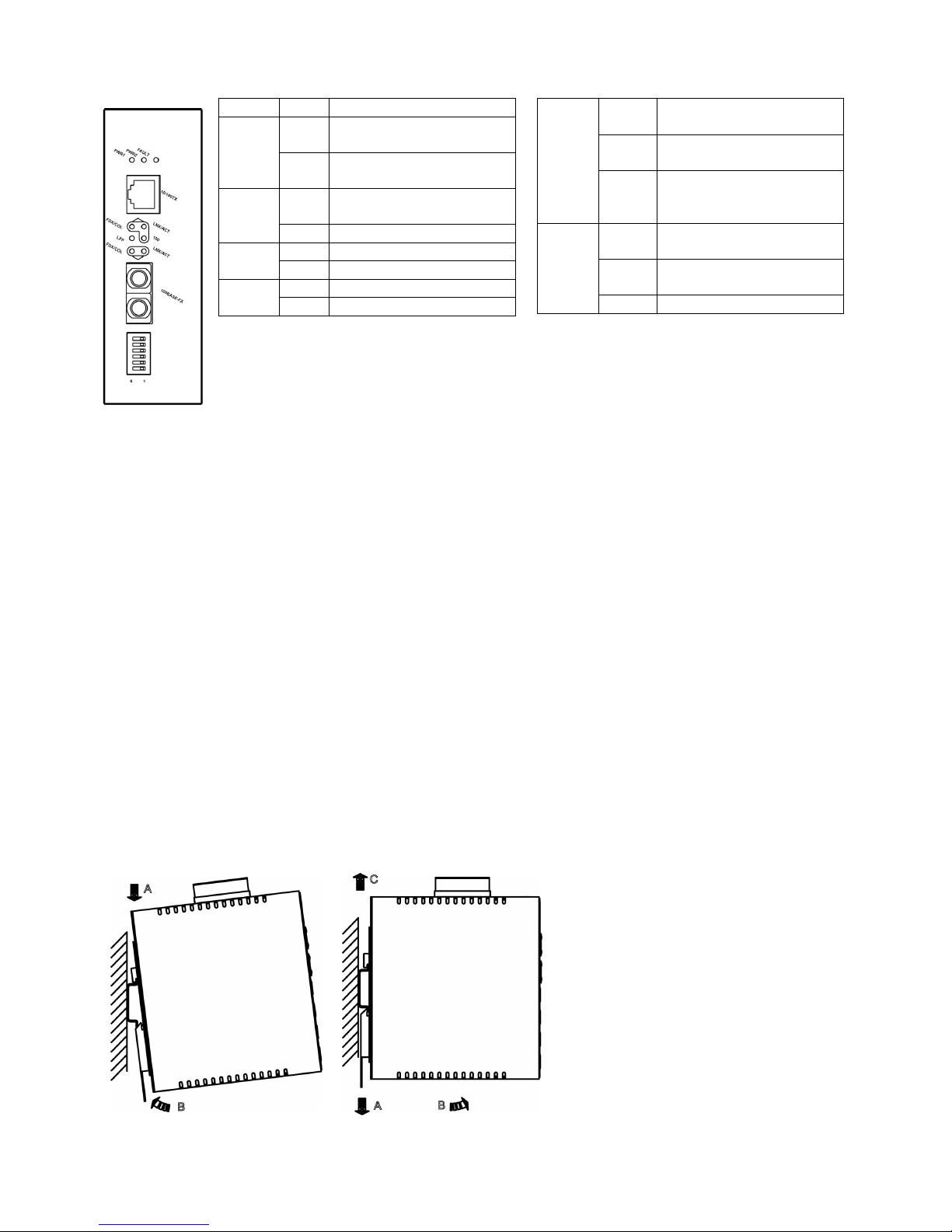
The Port Status LEDs
LEDs State Indication
Steady Power redundant system or ports
function abnormally
FAULT
Off Power redundant system and ports
function normally
Steady Power on
PWR stands for POWER
PWR1
PWR2
Off Power off
Steady Connection at the speed of 100Mbps100 (Mbps)
Off Connection at the speed of 10Mbps
Steady LFPT function enabled LFP
Off LFPT function disabled
Steady Valid network connection established
LNK stands for LINK
Flashing Transmitting or receiving data
ACT stands for ACTIVITY
LNK/ACT
Off Neither valid network connection
established nor
transmitting/receiving data
Steady Connection in full duplex mode
FDX stands for FULL-DUPLEX
Flashing Collision occurred
COL stands for COLLISION
FDX/COL
Off Connection in half-duplex mode
Functional Description
• Meets NEMA TS1/TS2 Environmental requirements: temperature, shock, and vibration for traffic control equipment.
• Meets IEC61000-6-2 EMC Generic Standard Immunity for industrial environment.
• Support 802.3/802.3u/802.3x. Auto-negotiation: 10/100Mbps, full/half-duplex; Auto MDI/MDIX.
• 100Base-FX: Multi mode SC or ST type; Single mode SC or ST type; WDM Single mode SC type.
• One DIP switch for configuring link-fault-pass-through, fixed speed, full/half duplex, and link down alarm.
• Alarms for power and port link failure by relay output. Relay contact rating with current 1A @ 30VDC, 0.5
A @ 120VAC.
• Operating voltage and Max. current consumption: 0.76A @ 12VDC, 0.38A @ 24VDC, 0.19A @ 48VDC. Power consumption: 9.12W Max.
• Power Supply: Redundant DC Terminal Block power inputs or 12VDC DC JACK with 100-240VAC external power supply.
• -40 to 75 (℃℃-40℉ to 167℉) operating temperature range. Tested for functional operation @ -40 to ℃ 85 (℃ -40℉ to 185℉).
• Supports Din-rail, Panel, or Rack Mounting installation.
• UL1604 Class 1, Division 2 Classified for use in hazardous locations (applicable to versions with terminal block power option).
This equipment is suitable for use in Class I, Division 2, Groups A, B, C and D OR non-hazardous locations only.
WARNING – EXPLOSION HAZARD – Do not disconnect equipment unless power has been removed or the area is known to be
non-hazardous.
WARNING – EXPLOSION HAZARD – Substitution of components may impair suitability for Class I, Division 2.
Assembly, Startup, and Dismantling
• Assembly: Place the media converter on the DIN rail from above using the slot. Push the front of the media converter toward the mounting
surface until it audibly snaps into place.
• Startup: Connect the supply voltage to start up the media converter via the terminal block (or DC JACK).
• Dismantling: Pull out the lower edge and then remove the media converter from the DIN rail.
 Loading...