

Page 1

User’s Guide
ED3541 Hardened Ethernet Extender
FastFind Links
Introduction
Unpacking and Installation
Page 2

All Rights Reserved
Dissemination or reproduction of this document, or its contents, is not authorized except where expressly
permitted. Violators are liable for damages. All rights reserved, for the purposes of patent application or
trademark registration.
Disclaimer of Liability
The information contained in this document is subject to change without notice. EtherWAN is not liable for any
errors or omissions contained herein or for resulting damage in connection with the information provided in this
manual.
Registered Trademarks
The following words and phrases are registered Trademarks of EtherWAN Systems Inc.
EtherOS™
Ethernet to the World™
All other trademarks are property of their respective owners.
Warranty
For details on the EtherWAN warranty replacement policy, please visit our web site at:
https://kb.etherwan.com
Products Supported by this Manual:
ED3541
Page 3

Revision
Document Version
Date
Description
A
Version 2
06/16/2015
Initial release
Preface
Audience
This guide is designed for the person who installs, configures, deploys, and maintains the Ethernet
network. This document assumes the reader has moderate hardware, computer, and Internet skills.
Document Revision Level
This section provides a history of the revision changes to this document.
Changes in this Revision
This is second version of this document.
iii
ED3541 Industrial Ethernet Extender User Guide
Page 4

Symbol
Meaning
Description
Note
Notes emphasize or supplement important points of the main text.
Tip
Tips provide helpful information, guidelines, or suggestions for performing tasks more
effectively.
Warning
Warnings indicate that failure to take a specified action could result in damage to the
device, or could result in serious bodily injury.
Electric Shock Hazard
This symbol warns users of electric shock hazard. Failure to take appropriate precautions
such as not opening or touching hazardous areas of the equipment could result in injury or
death.
Convention
Description
Bold
Indicates text on a window, other than the window title, including menus, menu options, buttons, fields, and labels.
Italic
Indicates a variable, which is a placeholder for actual text provided by the user or system. Angled brackets (< >) are
also used to indicate variables.
screen/code
Indicates text that is displayed on screen or entered by the user.
< > angled
brackets
Indicates a variable, which is a placeholder for actual text provided by the user or system. Italic font is also used to
indicate variables.
[ ] square
brackets
Indicates optional values.
{ } braces
Indicates required or expected values.
| vertical bar
Indicates that you have a choice between two or more options or arguments.
Document Conventions
This guide uses the following conventions to draw your attention to certain information.
Safety and Warnings
This guide uses the following symbols to draw your attention to certain information.
Typographic Conventions
This guide also uses the following typographic conventions.
iv
ED3541 Industrial Ethernet Extender User Guide
Page 5

Contents
Preface ..................................................................................................................... iii
Changes in this Revision ........................................................................................... iii
Document Conventions ............................................................................................ iv
Safety and Warnings ................................................................................................ iv
Typographic Conventions ......................................................................................... iv
Contents ................................................................................................................... v
1 Introduction ........................................................................................................... 7
Key Features ............................................................................................................. 8
Quick Start Guide ................................................................ ...................................... 9
2 Unpacking and Installation ................................................................................ 10
Unpacking the Hardware ......................................................................................... 11
Hardware Features .................................................................................................. 11
Front Panel ........................................................................................................ 11
Top Panel .......................................................................................................... 13
Side Panels ....................................................................................................... 13
Installing the Hardened Ethernet Extender .............................................................. 14
Preparing the Site .............................................................................................. 15
Installing the Hardened Ethernet Extender ........................................................ 15
Connecting to the 10/100 Mbps RJ-45 Port ....................................................... 16
Connecting to Ethernet Extender Port ............................................................... 16
Checking the Installation .................................................................................... 16
Applying DC Power ........................................................................................... 16
3 Troubleshooting.................................................................................................. 18
Troubleshooting Chart ............................................................................................. 19
Additional Troubleshooting Suggestions .................................................................. 20
Configuration ..................................................................................................... 20
v
ED3541 Industrial Ethernet Extender User Guide
Page 6

Hardened Ethernet Extender Integrity ................................................................ 20
Auto-Negotiation ................................................................................................ 20
Technology .............................................................................................................. 21
Power ...................................................................................................................... 21
Mechanical .............................................................................................................. 21
Interface .................................................................................................................. 22
Environment ............................................................................................................ 23
Regulatory Approvals .............................................................................................. 23
vi
ED3541 Industrial Ethernet Extender User Guide
Page 7
Topics:
Congratulations on your purchase of the ED3541 Hardened
Ethernet Extender from EtherWAN Systems, Inc. Your EtherWAN
Hardened Ethernet Extender is a state-of-the-art IEEE-compliant
network solution designed for users who require
high-performance to eliminate bottlenecks and increase
productivity.
To simplify installation, the Hardened Ethernet Extender is
shipped ready for use.
Key Features (page 8)
Quick Start Guide (page 9)
1 Introduction
Figure 1-1. ED3541 Hardened Ethernet Extender
7
ED3541 Industrial Ethernet Extender User Guide
Page 8

Key Features
This section summarizes the key features of the ED3541 Hardened Ethernet Extender.
One 10/100Base-TX Ethernet port with RJ-45 connector
Auto negotiation of speed and duplex mode on Ethernet port
Auto MDIX on Ethernet port
Complies with IEEE 802.3 10Base-T and IEEE 802.3u 100Base-TX standards
One Ethernet Extender port with RJ-11 connector or Termianl Block
Ethernet Extender port auto senses the speed
DIP switch for configuring Ethernet Extender Auto or Local mode, to turn on or off link down relay
Status LEDs
8
ED3541 Industrial Ethernet Extender User Guide
Page 9

Step
Description
For Reference, See…
1.
Find a Location for the Hardened Ethernet Extender
Set the Hardened Ethernet Extender on a flat surface, Wall-mount, or DIN-Rail mount.
“Preparing the Site” (page 15)
2.
Connect to the 10/100 Mbps Ethernet Port
Connect one end of a Category 5 or better Ethernet cable to the Ethernet port of a computer,
printer, network storage, or other network device.
Connect the other end to a 10/100 Mbps RJ-45 port on the Hardened Ethernet Extender.
“10/100 Mbps RJ-45 Port" (page 12)
and
“Connecting to the 10/100 Mbps RJ-45
Port” (page 16)
3.
Connect to the Ethernet Extender Port
Insert the voice grade copper wire between one pair of Ethernet Extenders via Ethernet
Extender port (RJ-11 connector or Terminal Block).
4.
Power On
Connect the DC power cord to the plug-able terminal block on the Ethernet Extender, and then
plug it into a standard DC outlet.
Connect the ground connection from the terminal block to the grounding surface.
Wait for the Hardened Ethernet Extender to complete its Power On Self Test.
Confirm that the LEDs for ports connected to a device are green. If not, replace the Ethernet
cable, and then check the port LED again.
“Applying DC Power” (page 16)
Quick Start Guide
The following procedure enables advanced users to get their Hardened Ethernet Extender up and
running in the shortest possible time. For detailed installation instructions, refer to the sections in the
right column below.
ED3541 Industrial Ethernet Extender User Guide
9
Page 10

Topics:
This chapter describes how to unpack and install the ED3541
Hardened Ethernet Extender.
Unpacking the
Hardware (page 11)
Hardware Features
(page 11)
Installing the Hardened
Ethernet Extender
(page 14)
2 Unpacking and Installation
10
ED3541 Industrial Ethernet Extender User Guide
Page 11

Unpacking the Hardware
Unpack the items and confirm that no items are missing or damaged. Your package should
include:
One ED3541 Hardened Ethernet Extender
One CD containing this user’s guide
If any item is damaged or missing, notify your authorized EtherWAN representative. Keep the
carton, including the original packing material, in case you need to store the product or return
it.
Hardware Features
The following sections describe the hardware features of the ED3541 Hardened Ethernet
Extender.
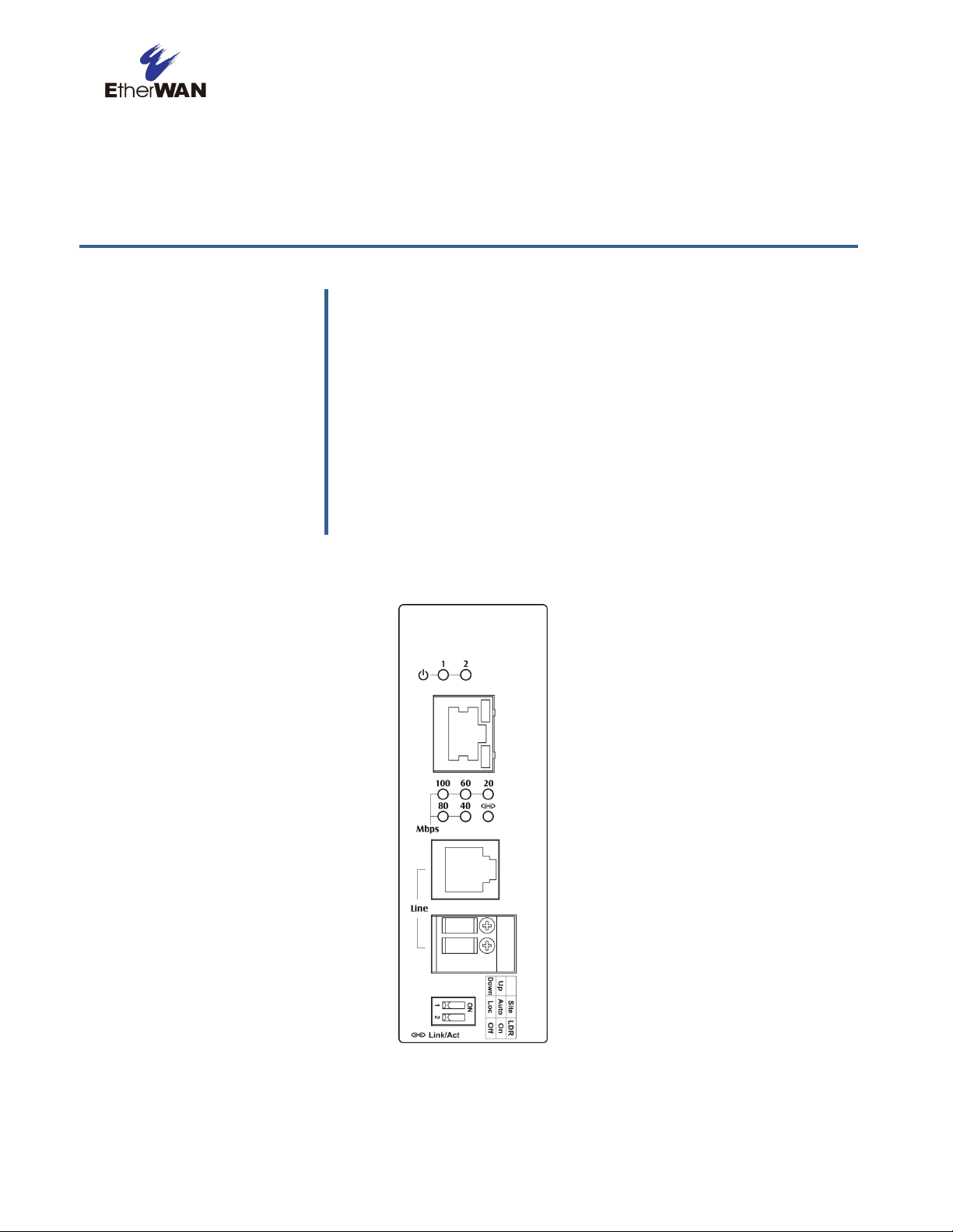
Front Panel
Figure 2-1 shows the front panels of the ED3541 Hardened Ethernet Extender.
Figure 2-1. Front Panel of the ED3541 Hardened Ethernet Extender
11
ED3541 Industrial Ethernet Extender User Guide
Page 12

10/100 Mbps RJ-45 Port
The ED3541 Hardened Ethernet Extender has one 10/100 Mbps RJ-45 port (see Figure 2-1).
This port is auto-sensing, auto-MDIX 10/100 Mbps port.
When you insert a cable into an RJ-45 port, the Hardened Ethernet Extender:
Determines whether the cable is a straight-through or crossover cable.
Automatically ascertains the maximum speed (10 or 100 Mbps) and duplex mode (half- or
full-duplex) of the attached device.
After determining this information, the Hardened Ethernet Extender configures the RJ-45 port
automatically to enable communications with the attached device, without requiring user
intervention.
Ethernet Extender Port
The ED3541 Hardened Ethernet Extender has one Ethernet Extender port (RJ-11 connector
or Terminal Block, see Figure 2-1).
Insert the voice grade copper wire between one pair of Ethernet Extenders via Ethernet
Extender port (RJ-11 connector or Terminal Block).
LEDs
The ED3541 front panel LEDs show power and link/activity status. Table 2-1 summarizes the
LEDs on the Hardened Ethernet Extender.
12
ED3541 Industrial Ethernet Extender User Guide
Page 13

LED
Color
Status
Description
PWR 1, 2
Green
ON
Receiving power.
OFF
Power off.
Ethernet Extender Port
Link/Activity
Green
ON
Connection is established.
OFF
No connection is established.
Flashing
Port is sending or receiving data.
Line Speed
Green
ON
Displays the link speed in Mbps.
10/100TX Port
Link/Activity
Green
ON
Valid network connection.
OFF
No data transmission on port.
Flashing
Port is sending or receiving data.
Speed
Yellow
ON
Link speed at 100Mbps.
OFF
Link speed at 10Mbps.
Table 2-1. Front Panel LEDs
Top Panel
The ED3541 top panel has a Termianl Block for connecting the external power supply.
Figure 2-2. Top Panel of the ED3541 Hardened Ethernet Extender
Side Panels
The ED3541 side panel has a product label that shows regulatory compliance, product serial
number, and other information.
13
ED3541 Industrial Ethernet Extender User Guide
Page 14

Installing the Hardened Ethernet Extender
Hardened Ethernet Extender installation involves the following steps:
1. Preparing the site. See page 15
2. Installing the Hardened Ethernet Extender. See page 15.
3. Connecting to the 10/100 Mbps RJ-45 Port. See page 16.
4. Connecting to Ethernet Extender Port. See page 16.
5. Checking the installation. See page 16.
6. Applying DC Power. See page 16.
14
ED3541 Industrial Ethernet Extender User Guide
Page 15

Characteristics
Requirements
Mounting
Desktop installations:
DIN-Rail installations:
Provide a flat table or shelf surface.
Top hat type 35mm.
Access
Locate the Hardened Ethernet Extender in a position that lets you access the front panel RJ-45 port
and Ethernet Extender port, view the front panel LEDs, and access the top-panel power connector.
Power source
Provide a power source within 6 feet (1.8 meters) of the installation location. Power specifications
for the Hardened Ethernet Extender are shown in Appendix A.
Environmental
Temperature:
Install the Hardened Ethernet Extender in a dry area, with ambient temperature between -40 and
75ºC (-40 and 167ºF). Keep the Hardened Ethernet Extender away from heat sources such as
direct sunlight, warm air exhausts, hot-air vents, and heaters.
Operating humidity:
The installation location should have a maximum relative humidity of 95%, non-condensing.
Ventilation:
Do not restrict airflow by covering or obstructing the top and side panels of the Hardened Ethernet
Extender. Keep at least 2 inches (5.08 centimeters) free on all sides for cooling.
Be sure there is adequate airflow in the room where you intend to install the Hardened Ethernet
Extender.
Operating conditions:
Keep the Hardened Ethernet Extender at least 6 ft (1.83 m) away from nearest source of
electromagnetic noise, such as a photocopy machine.
Stacking
If you intend to stack two or more Hardened Ethernet Extenders, be sure:
The mounting surface can safely support the stack.
There is adequate space around the stack for ventilation and cooling.
Preparing the Site
Before you install your Hardened Ethernet Extender, be sure your operating environment
meets the operating environment requirements in Table 2-2.
Table 2-2. Site Requirements
Installing the Hardened Ethernet Extender
You can install your Hardened Ethernet Extender on a flat surface or DIN-Rail with other
equipment.
If installing the Hardened Ethernet Extender on a desktop, shelf, or DIN-Rail, allow
sufficient ventilation space between the device and the objects around it.
ED3541 Hardened Ethernet Extender Dimensions: 42mm (W) x 90mm (D) x 100mm (H)
(1.65” (W) x 3.54” (D) x 3.94” (H))
15
ED3541 Industrial Ethernet Extender User Guide
Page 16

Connecting to the 10/100 Mbps RJ-45 Port
The front panel of the Hardened Ethernet Extender provides one 10/100 Mbps RJ-45 port
(see “10/100 Mbps RJ-45 Port” on page 12). To prevent ESD damage, follow normal board
and component handling procedures.
To connect devices to the Hardened Ethernet Extender’s 10/100 Mbps RJ-45 port:
1. Insert one end of a Category 5 or better Ethernet cable into a Ethernet port.
2. Insert the other cable end into the Ethernet port of a computer, printer, network storage, or
other network device.
Connecting to Ethernet Extender Port
The front panel of the Hardened Ethernet Extender provides one RJ-11 connector or
Terminal Block (see “Ethernet Extender Port” on page 12). To prevent ESD damage, follow
normal board and component handling procedures.
To connect the Hardened Ethernet Extender’s Ethernet Extender port:
Insert the voice grade copper wire between one pair of Ethernet Extenders via Ethernet
Extender port (RJ-11 connector or Terminal Block).
Checking the Installation
Before you apply power:
Inspect the equipment thoroughly.
Verify that all cables are installed correctly.
Check cable routing to make sure cables are not damaged or create a safety hazard.
Be sure all equipment is mounted properly and securely.
Applying DC Power
1. Connect the DC power cord to the plug-able terminal block on the Ethernet Extender, and
then plug it into a standard DC outlet.
2. Connect the ground connection from the terminal block to the grounding surface.
When you apply power:
All green Link/Activity LEDs blink momentarily.
The green Power LED goes ON.
The Link/Activity LEDs for every port connected to a device flash, as the Hardened
Ethernet Extender conducts a brief Power On Self-Test (POST).
16
ED3541 Industrial Ethernet Extender User Guide
Page 17

After the Hardened Ethernet Extender passes the POST, the Link/Activity LEDs for every
port connected to a device go ON. The Hardened Ethernet Extender is now functional and
ready to pass data.
If the Power LED is not ON, check that the power source is plugged in correctly and that the
power source is good. If this does not resolve the problem, see Chapter 3,
17
ED3541 Industrial Ethernet Extender User Guide
Page 18

Troubleshooting.
18
ED3541 Industrial Ethernet Extender User Guide
Page 19

Topics:
This chapter provides information about troubleshooting
the Hardened Ethernet Extender.
Troubleshooting Chart
(page 19)
Additional
Troubleshooting
Suggestions (page 20)
3 Troubleshooting
ED3541 Industrial Ethernet Extender User Guide
19
Page 20

Symptom
Cause
Solution
Power LED is OFF.
The Hardened Ethernet
Extender is not receiving
power.
Check the power connections for the Hardened Ethernet Extender at the
Hardened Ethernet Extender and the connected device.
Be sure all cables used are correct and comply with Ethernet
specifications.
Link/Activity LED is OFF
or intermittent.
Port connection is not
working.
Check the crimp on the connectors and be sure the plug is inserted
properly and locked into the port at both the Hardened Ethernet Extender
and the connecting device.
Be sure all cables used are correct and comply with Ethernet
specifications.
Check for a defective adapter card, cable, or port by testing them in an
alternate environment where all products are functioning.
File transfer is slow or
performance degradation
is a problem.
Half- or full-duplex setting on
the Hardened Ethernet
Extender and the connected
device are not the same.
Configure the Hardened Ethernet Extender and the attached device to
auto-negotiate.
A segment or device is
not recognized as part of
the network.
One or more devices are not
connected properly or cabling
does not meet Ethernet
guidelines.
Verify that the cabling is correct.
Be sure all connectors are securely positioned in the required ports.
Equipment may have been disconnected accidentally.
Collisions are occurring
on the connected
segment.
Some collisions are normal
when the connection is
operating in half-duplex
mode.
Recheck the settings of the device attached to the Hardened Ethernet
Extender port.
Be sure the Hardened Ethernet Extender and the attached device are
using the same duplex setting.
Be sure the Hardened Ethernet Extender and the attached device are set
to auto-negotiate.
Link/Activity LED is
flashing continuously on
all connected ports and
the network is disabled.
A network loop (redundant
path) has been created.
Break the loop by ensuring that there is only one path from any networked
device to any other networked device.
Troubleshooting Chart
Symptoms, causes, and solutions of possible problems.
Table 3-1. Troubleshooting Chart
ED3541 Industrial Ethernet Extender User Guide
20
Page 21

Additional Troubleshooting Suggestions
If the suggestions in Table 3-1 do not resolve your problem, refer to the troubleshooting
suggestions in this section.
Configuration
If problems occur after altering the Hardened Ethernet Extender’s network configuration,
restore the original connections and determine the problem by implementing the new
changes one step at a time. Be sure cable distances, repeater limits, and other physical
aspects of the installation do not exceed the Ethernet limitations.
Hardened Ethernet Extender Integrity
If required, verify the integrity of the Hardened Ethernet Extender by resetting it.
Auto-Negotiation
The 10/100 Mbps ports negotiate the correct duplex mode and speed since the Hardened
Ethernet Extender is configured for auto-negotiation (this is the Hardened Ethernet
Extender’s default setting) and the device at the other end of the link supports
auto-negotiation. If the device does not support auto-negotiation, the Hardened Ethernet
Extender determines only the speed correctly and the duplex mode defaults to half-duplex.
21
ED3541 Industrial Ethernet Extender User Guide
Page 22

Specification
Description
Standards:
IEEE802.3, 10BASE-T
IEEE802.3u, 100BASE-TX
IEEE802.3x, full-duplex and flow control
Forward and Filtering
Rate:
10 Mbps: 14,880 pps
100 Mbps: 148,810 pps
Processing Type:
Store-and-Forward
Half-duplex back-pressure and IEEE802.3x full-duplex flow control
Auto Negotiation
Auto MDI/MDIX
Specification
Description
Power Input:
12 to 48 VDC (Terminal Block)
Power Consumption:
4.2 W Max.
Specification
Description
Casing:
Aluminum case
IP30
Dimensions:
42 mm (W) x 90 mm (D) x 100 mm (H)
(1.65" (W) x 3.54" (D) x 3.94" (H))
Weight:
410 g (0.9 lb)
Installation:
DIN-Rail (Top hat type 35 mm) Mounting
Technology
Appendix A - Specifications
Power
Mechanical
ED3541 Industrial Ethernet Extender User Guide
22
Page 23

Specification
Description
Ethernet Port:
One 10/100BASE-TX port
Ethernet Extender Port:
One RJ-11 and Terminal Block port
DIP Switch
DIP Switch 1: Auto/Local mode
DIP Switch 2: Link down relay
LED Indicators:
Per unit: Power Status
Ethernet port: Link/Activity, Speed
Ethernet Extender port: Link/Activity, Line Speed
Distance (m)
Data Rate (Mbps)
300
100
400
80
600
60
800
40 … …
2600
1
Interface
Auto mode: This is the factory default setting. The Extender will automatically select the
Extender port to operate in Local or Remote mode.
Local mode: Operation mode of the Extender is fixed as Local mode.
A pair of Extenders can only have one Extender set to Local mode.
Connection establishment time for Extender port:
One Extender is set as Local mode, the other is set as Auto mode: Around 40 seconds.
A pair of Extenders are set to Auto mode: Connection establishment time may be longer,
sometimes the connection establishment time may be up to a few minutes.
The data rates will vary according to the quality of the connected cable. The information
below is only for reference of applications.
This distance/data rate information is measured according testing standard in EtherWAN
laboratory. The actual installation will be affected by the quality of copper wire and the impact
of noise disturbance. The connection speed will be affected.
NOTE: After making changes to the position of any DIP switch, the Ethernet Extender must be
rebooted for the new settings to take effect.
23
ED3541 Industrial Ethernet Extender User Guide
Page 24

Specification
Description
Operating Temperature:
-40°C to 75°C (-40°F to 167°F)
Storage Temperature:
-40°C to 85°C (-40°F to 185°F)
Ambient Relative
Humidity:
5% to 95% (non-condensing)
Specification
Description
ISO:
Manufactured in an ISO9001 facility
Safety:
UL60950-1, EN60950-1
EMI:
FCC Part 15B, Class A
EN61000-6-4: EN55022, EN61000-3-2, EN61000-3-3
EMS:
EN61000-6-2:
EN61000-4-2 (ESD Standard)
EN61000-4-3 (Radiated RFI Standards)
EN61000-4-4 (Burst Standards)
EN61000-4-5 (Surge Standards)
EN61000-4-6 (Induced RFI Standards)
EN61000-4-8 (Magnetic Field Standards)
Environmental Test
Compliance
IEC60068-2-6 Fc (Vibration Resistance)
IEC60068-2-27 Ea (Shock)
FED STD 101C Method 5007.1 (Free fall w/ package)
Environment
Regulatory Approvals
24
ED3541 Industrial Ethernet Extender User Guide
Page 25

USA Office
4570 E. Eisenhower Circle
Anaheim, CA 92807
TEL: +1-714-779-3800
Email: info@etherwan.com
Pacific Rim Office
8F., No.2, Alley 6, Lane 235, Baoqiao Rd.,
Xindian District, New Taipei City 231,
Taiwan (R.O.C.)
TEL: +886 -2- 6629-8986
Email: info@etherwan.com.tw
EtherWAN System, Inc.
www.etherwan.com
EtherWAN has made a good faith effort to ensure the accuracy of the information in this document and disclaims
the implied warranties of merchantability and fitness for a particular purpose, and makes no express warranties,
except as may be stated in its written agreement with and for its customers.
EtherWAN shall not be held liable to anyone for any indirect, special or consequential damages due to omissions
or errors. The information and specifications in this document are subject to change without notice.
Copyright 2016. All Rights Reserved.
All trademarks and registered trademarks are the property of their respective owners
ED3541 Hardened Ethernet Extender User Guide
April 15, 2016
Document version: Version 1.2
 Loading...