

Page 1

12-Bay Media Converter System
Preface
This manual describes how to install and use the 12-Bay Media
Converter System. The system introduced here is capable of
housing up to twelve media converters, each of which offers a
single channel media conversion solution:
10/100Base-TX ↔ 100Base-FX
100Base-TX ↔ 100Base-FX
100Base-FX ↔ 100Base-FX
10/100/1000Base-TX ↔ 1000Base-SX/LX
1000Base-T ↔ 1000Base-SX/LX
1000Base- SX/LX ↔ 1000Base-SX/LX
In this manual, you will find:
• An introduction to the system
• Product features
• Illustrative LED functions
• Installation instructions
• Specifications
User’s Manual 1
Page 2

12-Bay Media Converter System
Table of Contents
PREFACE 1
TABLE OF CONTENTS 2
RODUCT OVERVIEW 3
P
12-BAY MEDIA CONVERTER SYSTEM 3
PACKAGE CONTENTS 3
PRODUCT FEATURES 4
FRONT PANEL DISPLAY 4
Front Panel 4
Understanding LEDs 5
INSTALLATION 8
SELECTING A SITE FOR THE EQUIPMENT 8
CONNECTING TO POWER 9
SPECIFICATIONS 10
2 User’s Manual
Page 3
12-Bay Media Converter System
Product Overview
12-Bay Media Converter System
The 12-Bay Media Converter System can house up to twelve media
converters in a 1U standard 19” rackmountable size. The front
panel of the 12-Bay Media Converter System provides status LEDs.
Figure 1: 12-Bay Media Converter System
Package Contents
When you unpack the product’s package, you should find the items
listed below:
3
12-Bay Media Converter System
3
Two AC power cords
3
User’s manual
3
Rackmount ears with screws
Please inspect the contents, and report any apparent damage or
missing items immediately to your authorized reseller.
User’s Manual 3
Page 4

12-Bay Media Converter System
Product Features
♦ Houses twelve channels of media conversion
♦ Front panel status LEDs
♦ Standard 19” rackmountable size, 1U high
♦ 2 Redundant Power Supplies
♦ 12-Bay 10/100Base-TX to 100Base-FX converters,
100Base-TX to 100Base-FX converters, 100Base-FX to
100Base-FX converters, 10/100/1000Base-TX to
1000Base-SX/LX converters, 1000Base-T to 1000BaseSX/LX converters, or 1000Base-SX/LX to 1000BaseSX/LX converters
Front Panel Display
FRONT PANEL
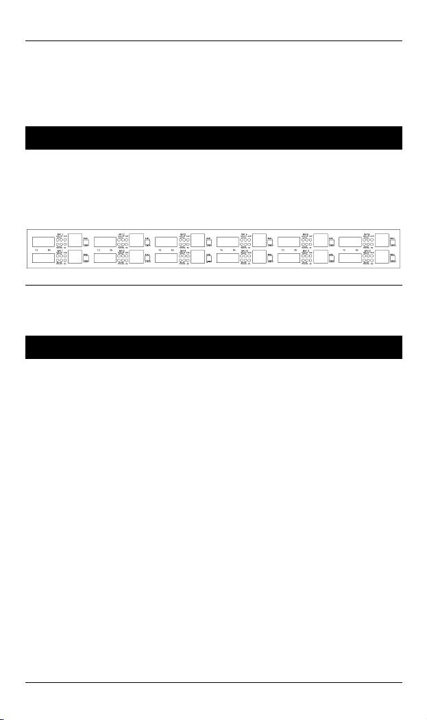
The front panel of this 12-Bay Media Converter System shows the
layout of the twelve media converter channels.
There are 12 sets of LED indicators, which provide you with
instant feedback on the status of each media converter channel.
Figure 2: Front Panel of the 12-Bay Media Converter System
4 User’s Manual
Page 5

12-Bay Media Converter System
UNDERSTANDING LEDS
10/100TX to 100FX Media Converter
LEDs State Indication
PWR
LNK/ACT
FDX/COL
100TX to 100FX Media Converter
LEDs State Indication
ACT
Steady Power on
PWR stands for POWER
Off Power off
Steady Connection at the speed of 100Mbps 100 (Mbps)
Off Connection at the speed of 10Mbps
Steady A valid network connection established
LNK stands for LINK
Flashing Transmitting or receiving data
ACT stands for ACTIVITY
Off
Steady Connection in full duplex mode
Flashing Collision occurred
Off Connection in half-duplex mode
Steady Power on Power
Off Power off
Steady Connection at the speed of 100Mbps LNK
Off No connection at the Speed of 100Mpbs
Steady A valid network connection established
Flashing Transmitting or receiving data
Off
Neither valid network connection
established nor transmitting/receiving
data.
FDX stands for FULL-DUPLEX
COL stands for COLLISION
Neither valid network connection nor
transmitting/ receiving data
User’s Manual 5
Page 6

12-Bay Media Converter System
100FX to 100FX Media Converter
LEDs State Indication
Steady Power on PWR
Off Power off
SDA/ SDB
(100FX)
Steady A valid network connection established,
Transmitting and Receiving
Off
Neither valid network connection nor
transmitting established
10/100/1000TX to 1000SX/LX Media Converter
LEDs State Indication
Steady Power feeding in PWR
Off No power
LNK/ACT
(TX)
LNK/ACT
(SX/LX)
FDX
1000 Steady Connection at 1000Mbps speed.
100 Steady Connection at 100Mbps speed.
1000, 100 Off Connection at 10Mbps speed.
Steady A valid network connection established.
LNK stands for LINK.
Flashing Transmitting and receiving data.
ACT stands for ACTIVITY.
Off Neither connection nor activity existing.
Steady A valid network connection established.
LNK stands for LINK.
Flashing Transmitting and receiving data.
ACT stands for ACTIVITY.
Off Neither connection nor activity existing.
Steady Connection in full duplex mode.
FDX stands for FULL DUPLEX.
Flashing Collision occurred.
Off Connection in half duplex mode
6 User’s Manual
Page 7

12-Bay Media Converter System
1000T to 1000SX/LX Media Converter
LEDs State Indication
Steady Power feeding in Power
Off No power
LNKC
Steady
TX port: A valid network connection
established. LNKC stands for LINK/Copper
Off No connection
LNKF
Steady
FX port: A valid network connection
established. LNKF stands for LINK/Fiber
Off No connection
FDX/COL Steady Connection in full duplex mode
FDX stands for FULL DUPLEX
Steady Receiving data RX
Off No reception
Steady Transmitting data TX
Off No transmission
1000SX/LX to 1000SX/LX Media Converter
LEDs State Indication
Steady Power feeding in Power
Off No power
SDA
Steady Port A Signal Detect:
A valid network connection established.
Off No connection
SDB
Steady Port B Signal Detect:
A valid network connection established.
Off No connection
User’s Manual 7
Page 8

12-Bay Media Converter System
Installation
Selecting a Site for the Equipment
As with any electric device, you should place the equipment where
it will not be subjected to extreme temperatures, humidity, or
electromagnetic interference. Specifically, the site you select
should meet the following requirements:
- The ambient temperature should be between 32 and 113
degrees Fahrenheit (0 to 45 degrees Celsius).
- The relative humidity should be less than 95 percent,
non-condensing.
- Surrounding electrical devices should not exceed the
electromagnetic field (RFC) standards for IEC 801-3, Level 2
(3V/M) field strength.
- Make sure that the equipment receives adequate ventilation.
Do not block the ventilation holes on each side of the
equipment or the fan exhaust port on the side or rear of the
equipment.
- The power outlet should be within 6 feet (1.8 meters) of the
equipment.
8 User’s Manual
Page 9

Connecting to Power
12-Bay Media Converter System
Step 1: Connect the supplied AC power cords to the receptacles on the
rear panel of the system.
Step 2: Attach the plugs from each of the dual power supplies into
standard AC outlets with a voltage range from 100~240VAC.
Step 3: Turn on the system by flipping the ON/OFF switches beside the
dual power supplies’ receptacles to the ON position.
Step 4: The power LED of each media converter will shine after turning on
the system.
Step 5: The link LED of each media converter will shine after connecting
twisted pair copper cabling between the TX port (or fiber optic
cabling between the FX port) and another working networked
device.
Figure 3: Rear view of the 12-Bay Media Converter System
User’s Manual 9
Page 10

12-Bay Media Converter System
Specifications
Applicable
Standards
Speed –
10Base-T
100Base-TX/FX
1000Base-T/SX/LX
Forwarding rate
Dimensions
Weight
Power
Power Consumption
Operating
Temperature
Storage
Temperature
Humidity
Emission
Compliance
IEEE 802.3 10Base-T, IEEE 802.3u
100Base-TX/FX, IEEE 802.3ab
1000Base-T, IEEE 802.3z 1000BaseSX/LX
10/20Mbps for half/full-duplex
100/200Mbps for half/full-duplex
2000Mbps for full-duplex
14,880pps for 10Mbps
148,810pps for 100Mbps
1,488,100pps for 1000Mbps
440mm (W) × 243mm (D) × 45mm (H)
(17.32” (W) x 9.57” (D) x 1.77” (H))
3.1Kg (6.82lbs.)
100 ~ 240VAC, 50 ~ 60Hz
55.2W Max.
0℃ ~ 45℃ (32℉ ~ 113℉)
-10℃ ~ 70℃ (14℉ ~ 158℉)
5 ~ 95%, non-condensing
CE Mark Class A, FCC Part 15 Class A
10 User’s Manual
 Loading...