

EtherTek Circuits RMS-200, RMS-300 Owner's Manual

RMS-200
(C) EtherTek Circuits

O w n e r s
M a n u a l

R E M O T E M O N I T O R I N G M A D E E A S Y !
RMS-200 Owners Manual (Rev 1b)
June 6, 2011
EtherTek Circuits
473 Corina Ave • Unit 38
Princeton, B.C. Canada

V0X 1W0 • Phone 250.295.6794
Table of Contents
Introduction ................................................................................ 1
Possible Applications ................................................................. 1
A/C or Battery Powered Microwave, Telephony, Network Equipment ... 1
Configuration .............................................................................. 4
Setting up RMS-200 .......................................................................... 4
RMS-200 is powered up, Now What ? .............................................. 5
Installation .................................................................................. 7
Basic installation example 1 .............................................................. 7
Basic installation example 2 .............................................................. 8
Basic installation example 3 .............................................................. 9
Basic installation example 4 ............................................................ 10
The Relays ............................................................................... 11
Need More Relays? ........................................................................ 15
The Voltmeters ......................................................................... 18
Voltmeter Graphs ............................................................................ 21
How to measure amperage by using a shunt ................................. 22
Need More Voltmeters? .................................................................. 26
The Temperature ..................................................................... 30
The I/O Pins and Push Buttons ................................................ 32
GPIO
........................................................................................................ 34
ALARMS
........................................................................................................ 34
PUSH BUTTONS ............................................................................ 35
USB Support ............................................................................ 36
CAMERAS ...................................................................................... 36
USB to SERIAL ............................................................................... 36
USB WIRELESS ............................................................................. 36
GENERAL USB SUPPORT ........................................................... 36
Firmware Upgrades ................................................................. 37
Web Based Upgrade ....................................................................... 37
........................................................................................................ 38
........................................................................................................ 38

FTP Based Upgrade ....................................................................... 39
Downloads ............................................................................... 42
Specs ....................................................................................... 42
Base System 256Mb Flash / 64Mb Ram ........................................ 42
General Board Information .............................................................. 42
Block Diagram ................................................................................. 43
Graphs ..................................................................................... 44
Warranty .................................................................................. 45

R E M O T E M O N I T O R I N G M A D E E A S Y !
Introduction
RMS-200 Is a unique remote monitoring, data acquisition, and control device
specifically designed for use with Battery powered wireless internet repeater sites, or
other AC & DC powered remote equipment
RMS-200 Has ultra low power consumption and won't put a drain on your power
source. Uses less than 2 watts.
RMS-200 Is powered by DC voltage from 10 to 60 volts.
RMS-200 Uses embedded Ethernet technology for internet data acquisition and
remote voltage monitoring.
RMS-200 Uses the LINUX operating system for versatility, stability, and security.
RMS-200 Gives you the situational awareness you need to keep your equipment
operational and reliable.
Possible Applications
A/C or Battery Powered Microwave, Telephony, Network Equipment
Use RMS-200 to monitor battery levels, room temperature, signal strength (RSSI) on
radios and more. RMS-200 has 6 onboard isolated voltmeters giving it the ability to
measure DC voltage from -100 to +100 volts with 24 bit accuracy. RMS-200 also has
3 power relays giving it the unique ability to turn on/off devices remotely using an
Internet connection. Use the power relays to remote start a generator. RMS-200 has 5
dedicated input pins used for door alarms or to monitor motion sensors. RMS-200 has
a full featured serial port, control modems, cell phones, gsm modules, and other
devices that use serial communication. RMS-200 has two USB 2.0 ports that supports
several USB devices concurrently using a USB hub. Control USB cameras, store data
on USB flash drives, control USB speakers etc. RMS-200 has input and output pins
used to control your own custom devices. RMS-200 can alert you via email or SMS
messages when your battery bank is low. RMS-200 has ping monitor software that
allows you to monitor network devices and alert you to failure and possibly power
cycle the device. Monitor all this information remotely over an Internet connection
using an ordinary web browser. RMS-200 gives you direct hardware control of fans,
lights, computers, cameras, modems, radios, etc... No more guessing what your
battery levels are. No more wondering if your signal strengths are at an acceptable
level. No more long drives to reset a fussy radio. Let RMS-200 do this all remotely via
the Internet.
1

R E M O T E M O N I T O R I N G M A D E E A S Y !
Features
• Six layer PCB with Nickel Immersion Gold plating and red solder mask.
• 400 - MHz Arm Processor (500 Mips !).
• 256 - megs of Nand Flash. Create and store custom applications.
• 64 - megs of SD-Ram.
• Dual Low Noise Switching Power Supplies accepts 8 - 60 vdc input. Can be powered
directly from 12, 24, or 48 volt battery banks.
• Battery backed-up, real time clock.
• One onboard temperature sensor –25c +100c.
• Six 24 bit isolated voltmeters (+/- 100 VDC). Each voltmeter has its own 24 bit Delta
Sigma ADC.
• Each voltmeter can be put into low voltage shunt mode (+/- 2 VDC).
• Two Power Relays for devices using 1 – 240v -5 amps AC/DC current.
• One Power Relay for devices using 1 – 240v -15 amps AC/DC current.
• Two programmable push buttons.
• Four general purpose I/O pins.
• Five dedicated alarm pins.
• Power output port, 5.0vdc (500ma).
• One full serial port for controlling cell phones, modems, etc.
• One console serial port.
• Two USB 2.0 ports for cameras, wireless clients, extra Ethernet, etc.
• Runs real Linux! 2.6.33 kernel.
• Send SMS messages, Email alerts, SNMP traps, Remote Syslog Messages.
• Ping watchdog, power cycle equipment after a set amount of ping timeouts.
• Command line utilities: ping, ftp, email, relays, etc.
• Flash new firmware over the internet.
• Duel Watchdog Reset circuits, processor integrated, and extra hardware.
2

R E M O T E M O N I T O R I N G M A D E E A S Y !
• Control RMS-200 via web page, telnet, ssh, or snmp.
• Full SNMP v1, v2, v3 support (default v3).
• Supports external USB relays and voltmeters.
• Hardware is user accessible from files on the board.
• Make your own utilities and scripts to upload. (Bash, PHP, Python, Lua)
• Pluggable connectors for ease of use.
A partial list of programs and packages included:
SQLlite v3 database, Telnet ,Drop Bear SSH, Light Http and Https Server, Pro FTP, Cron
scheduling agent, Busy Box, PPP, Net SNMP, NanoCom, Easy Edit, Nano, and Vi,
Fping, SMTP email client, IPtables, Lrz and Lsz, Open SSL, Modbus Library, RRD Tool,
USB Web Camera Support.
A programmers dream:
RMS-200 comes with PHP, Python, and Lua. Make your own custom monitoring
programs and upload them to the RMS-200 board, or create your own branded interface!
3
R E M O T E M O N I T O R I N G M A D E E A S Y !
Configuration
Setting up RMS-200
Connect 8 - 60 volts dc power (minimum 500 ma) to the green terminal block that is
beside the on/off switch (See figure 1). Connect an Ethernet cable to the rj-45 jack on the
RMS-200 board. Turn the device on with the on/off switch. It takes the RMS-200 board
approximately 30 seconds to bring up the Linux operating system. The RMS-200 will
signal it is ready by first blinking the green status light in a continuous heartbeat
sequence. After a few seconds the red alarm leds will display a light sequence. The
board is now fully booted up and is ready for configuration.
Note1: RMS-200 units should be mounted inside a steel enclosure that is grounded
properly to prevent Electro Magnetic Interference.
FIGURE 1
4

R E M O T E M O N I T O R I N G M A D E E A S Y !
RMS-200 is powered up, Now What ?
We recommend configuring RMS-200 before deploying it in the field. Simply plug RMS200 into your network or computer using an Ethernet cable (Straight or Cross).
When RMS-200 is turned on it boots the Linux operating system and uses the values
stored in its configuration files to bring up the system. The default values consist of an IP
address, username, and password. The default IP address is 10.10.10.10. The default
username is root. The default password is pass.
Note: You may at anytime restore the RMS-200 device to
factory default values by pressing and holding down the
micro push button #2 located near the console port and then
turning the RMS-200 device on with the on/off switch.
Release the button when the alarm leds start to flash. When
the alarm leds stop flashing, the RMS-200 unit will be ready
to configure.
Give your computer an ip address in the 10.10.10.X class. For instance use 10.10.10.1.
Set your computers Netmask to 255.255.255.0 There is no need to set a Gateway at this
time. Open your favorite web browser and enter 10.10.10.10 into the address bar, press
enter or the go button. You should be presented with a password box like the one below.
Enter in the default username and password then press the OK button. You will be taken
to the RMS-200 Home page. This page contains an overview of all of the functionality of
the RMS-200 board.
5

R E M O T E M O N I T O R I N G M A D E E A S Y !
In the left side panel, click on the Setup icon. This takes you to the System Setup area
shown below.
Here you will want to visit the following areas: Company Setup , Network , System Time ,
and Change Password. Adjust the Station Name, Location, Domain Name, IP Address,
Subnet Mask, Gateway, DNS, and password you want the RMS-200 device to have.
6
R E M O T E M O N I T O R I N G M A D E E A S Y !
Caution must be taken when configuring the device, entering incorrect values may cause
you to lose connectivity with the device, forcing the need for a factory reset. Once you
have RMS-200 configured properly, it is ready to deploy in the field. Below are some
basic examples of how to install the RMS-200 unit.
Installation
Basic installation example 1
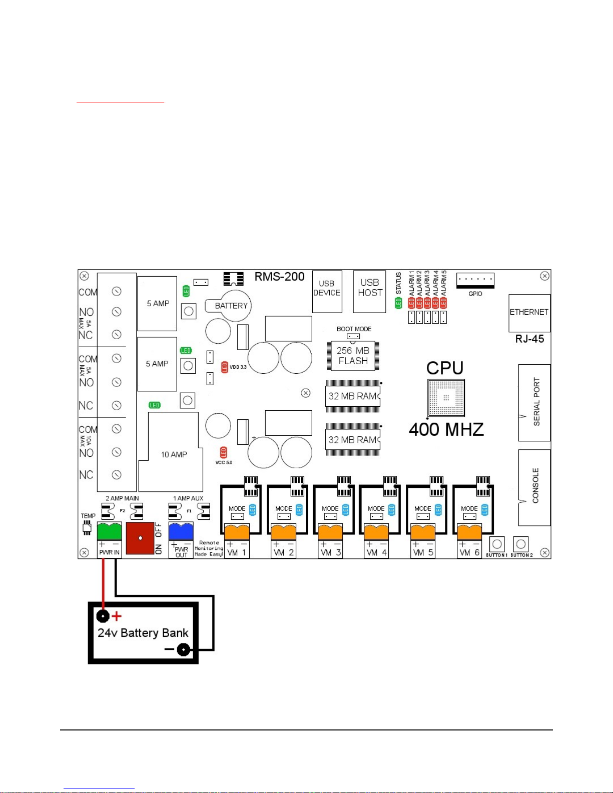
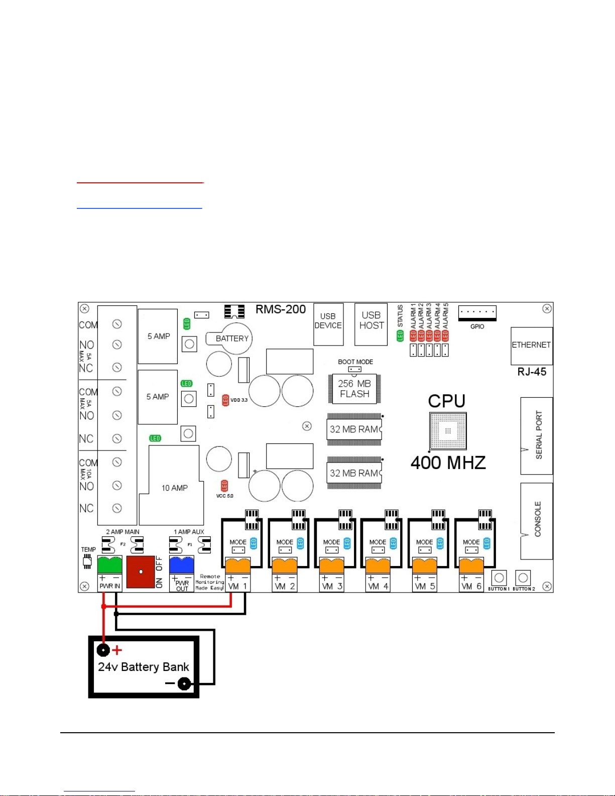
Monitoring your Battery Bank
To monitor your main battery power supply, run a wire from the positive side of the
battery bank to one of the Voltmeter positive inputs. Run a second wire from the negative
side of the battery bank to the corresponding Voltmeter negative input as shown in Figure
2. Connect RMS-200 to the internet with a common Ethernet cable and monitor the
voltage level of your battery bank with a web browser.
FIGURE 2
7
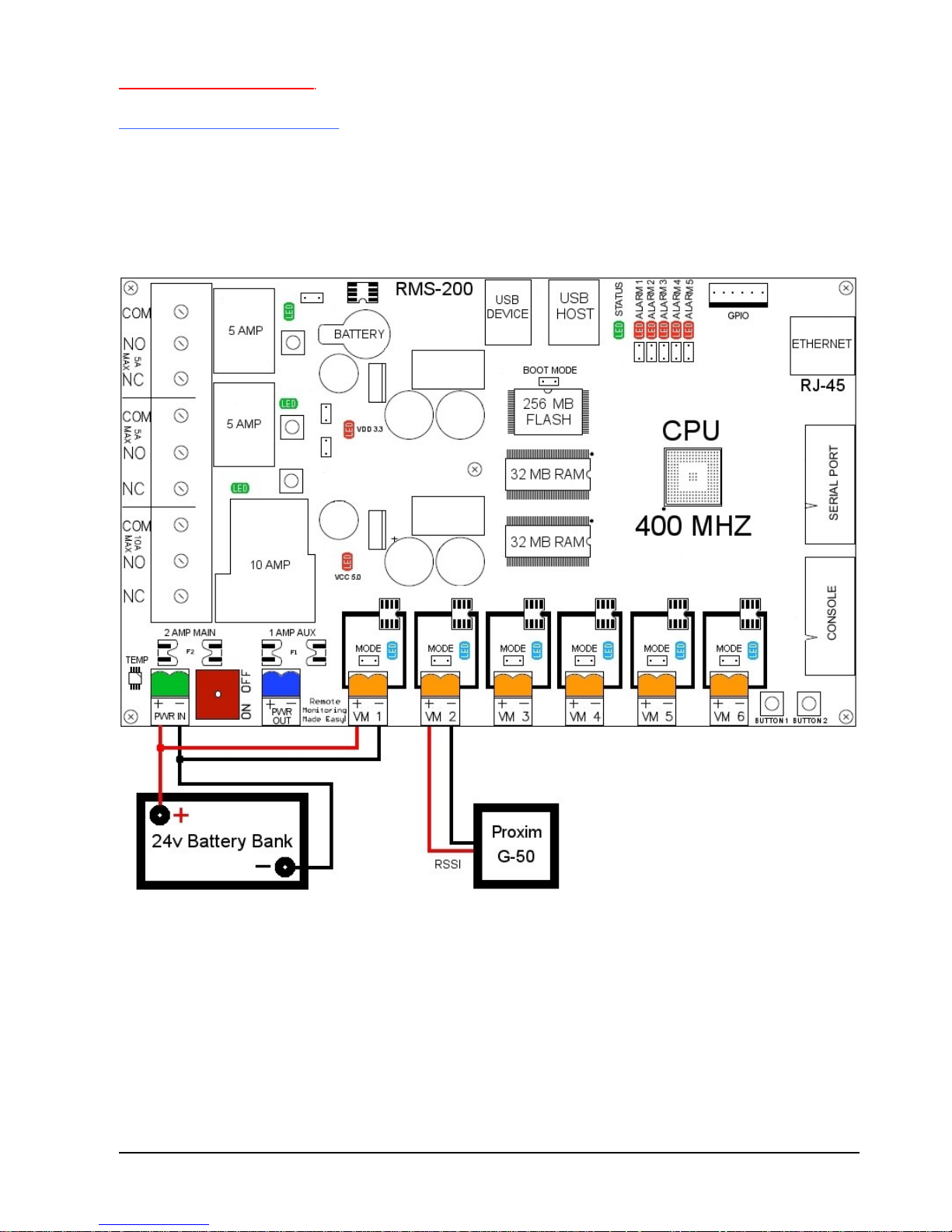
Basic installation example 2
Signal strength on Link CX Radios
Radios that have an external RSSI port for checking signal strength can be monitored
with ease. Simply attach the RSSI output from the radio to one of the Voltmeter inputs on
the RMS-200 board (see Figure 3). Monitor the signal strength of your radios with a web
browser and/or have RMS-200 alert you by email if the signal falls below a certain
threshold.
FIGURE 3

Basic installation example 3
Turning Devices ON/OFF
To make any device remotely reset able, simply cut one of the wires in the power cord of
a device. Attach one side of the cut wire to the COM terminal on one of the Power
Relays. Attach the other side of the cut wire to the NC (normally closed) terminal on the
corresponding Power Relay. Reset your device at any time using RMS-200. Note: in the
Normally Closed configuration, power still flows to your device even when the RMS-200
device is turned off. Virtually any 1 to 240 volt AC or DC device can be turned ON/OFF
remotely this way. The two small Power Relays can pass up to 5 amps each, the larger
Power Relay up to 15 amps!. For devices that should be by default turned off, use the
COM and NO (normally open) configuration. Figure 4 illustrates just one of the many
ways you can set up devices for remote reset.
FIGURE 4

Basic installation example 4
Using the alarm pins to monitor door contacts
To give your equipment room some security you can use widely available common door
contacts. These contacts allow current to flow through them when they are in close
proximity with each other. RMS-200 can sense when the contacts are together or apart.
Program the alarm pins to send an email, run a custom file, and/or toggle a relay when
the door gets opened. The diagram below (figure 5) shows how to use Alarm pin 5 to
monitor door contacts.
Note1: the LED5 light is on when the contacts are together. This is the armed position.
Note2: each Alarm pin has a corresponding LED.
FIGURE 5

The Relays
FIGURE 6
RMS-200 has three power relays for remote control of AC/DC powered equipment. Each
relay has a manual override button that can toggle the relay; useful for on-site testing.
Each relay also has a jumper shunt connector that allows the relay to be engaged
manually for hands free testing.
Control of each relay can be done with a web browser. The picture below shows a portion
of the RMS-200 relays web interface. In the picture below all relays are in the default
"Normally Closed" position. By clicking on the relay 1 icon…
 Loading...