

Page 1

SFFR
-
6
USER MANUAL
Small Form Factor Tactical Repeater and Base Station
SFFR-6 User Manual
Version 5.04 | May 2019
Page 2

SFFR-6 User Manual
Contents
1 Introduction ................................................................................................................. 5
1.1 Overview ..................................................................................................................................................................... 6
1.2 Document Conventions............................................................................................................................................... 6
1.3 Features ...................................................................................................................................................................... 7
1.4 Technical Specifications .............................................................................................................................................. 9
2 Getting Started .......................................................................................................... 10
2.1 Package Contents ...................................................................................................................................................... 11
2.2 Overview ................................................................................................................................................................... 12
2.2.1 Locking Clamps ................................................................................................................................................... 12
2.2.2 Lid ....................................................................................................................................................................... 12
2.2.3 External Interfaces ............................................................................................................................................. 13
2.2.3.1 AC Power Connector ...................................................................................................................................... 13
2.2.3.2 DC Power Connector ...................................................................................................................................... 13
2.2.3.3 Ethernet Connector ........................................................................................................................................ 13
2.2.3.4 Tx/Rx Antenna Connector .............................................................................................................................. 13
2.2.4 Internal Modules ................................................................................................................................................ 14
2.2.5 Battery Compartment ........................................................................................................................................ 14
2.2.6 Control Module .................................................................................................................................................. 15
2.2.6.1 Ethernet Connector ........................................................................................................................................ 15
2.2.6.2 Accessory Connector ...................................................................................................................................... 15
2.2.6.3 Status Display ................................................................................................................................................. 16
2.2.6.4 Function Button 1 ........................................................................................................................................... 16
2.2.6.5 Power/Function Button 2 ............................................................................................................................... 16
2.2.6.6 Rotary Dial/Button ......................................................................................................................................... 16
2.2.6.7 Rx LED ............................................................................................................................................................. 16
2.2.6.8 Tx LED ............................................................................................................................................................. 16
2.2.6.9 Power/Status LED ........................................................................................................................................... 16
2.2.7 Radio Module ..................................................................................................................................................... 17
2.2.8 Duplexer ............................................................................................................................................................. 17
2.2.9 Power Amplifier.................................................................................................................................................. 17
3 Configuration ............................................................................................................. 18
3.1 Before you begin ....................................................................................................................................................... 19
3.1.1 About GoBox Configuration ............................................................................................................................... 19
3.1.2 About Operational Profiles ................................................................................................................................. 19
3.1.3 About Duplexer Group Tags ............................................................................................................................... 19
3.1.4 What you need to program and test your GoBox .............................................................................................. 20
3.1.4.1 Laptop or PC with an Ethernet Interface ........................................................................................................ 20
3.1.4.2 Mobile/Portable Radios ................................................................................................................................. 20
3.2 Connecting to your GoBox configuration interface .................................................................................................. 20
3.2.1 Direct Connection ............................................................................................................................................... 20
3.2.2 Connection via a Network .................................................................................................................................. 20
3.3 Managing Operational Profiles ................................................................................................................................. 22
3.3.1 Adding a P25 Conventional Repeating Profile .................................................................................................... 22
3.3.1.1 Standalone Mode ........................................................................................................................................... 22
3.3.1.2 Networked Mode ........................................................................................................................................... 23
3.3.2 Adding an Analog Conventional Repeating Profile ............................................................................................. 24
3.3.2.1 Standalone Mode ........................................................................................................................................... 24
3.3.2.2 Networked Mode ........................................................................................................................................... 25
3.3.3 Adding a Mixed Mode Conventional Repeating Profile...................................................................................... 26
3.3.3.1 Standalone Mixed Mode ................................................................................................................................ 26
Doc ID: ES1002-UM02-v504
Copyright © 2019 Etherstack London Limited
Page ii
Page 3

SFFR-6 User Manual
Contents
3.3.3.2 Network Mixed Mode .................................................................................................................................... 26
3.3.4 Profile Field Descriptions .................................................................................................................................... 27
3.3.4.1 Common Profile Fields ................................................................................................................................... 27
3.3.4.2 P25 Profile Fields ............................................................................................................................................ 27
3.3.4.3 Analog Profile Fields ....................................................................................................................................... 27
Networked Profile Fields .............................................................................................................................................. 28
RNC Networked Profile Fields ...................................................................................................................................... 28
DFSI Networked Profile Fields ...................................................................................................................................... 28
3.3.5 Setting the Operational Profile Order ................................................................................................................ 29
3.4 Managing Duplexers ................................................................................................................................................. 30
3.4.1 Writing a Duplexer Group Tag ............................................................................................................................ 30
3.4.2 Setting the start-up profile for a Duplexer ......................................................................................................... 31
4 Using the GoBox ........................................................................................................ 33
4.1 Turning your GoBox On ............................................................................................................................................. 34
4.2 Selecting an Operational Profile................................................................................................................................ 34
4.2.1 Front Panel ......................................................................................................................................................... 34
4.2.2 Web Configuration Interface .............................................................................................................................. 34
4.3 Stopping Repeater Operation ................................................................................................................................... 35
4.3.1 Front Panel ......................................................................................................................................................... 35
4.3.2 Web Interface ..................................................................................................................................................... 36
4.4 Checking GoBox Status.............................................................................................................................................. 36
4.4.1 Status Window ................................................................................................................................................... 36
4.4.1.1 Checking Battery Status ................................................................................................................................. 36
4.4.1.2 Checking External Power Source .................................................................................................................... 37
4.4.1.3 Checking the current operational profile ....................................................................................................... 38
4.4.2 Web configuration interface .............................................................................................................................. 38
4.4.2.1 Checking Battery Status ................................................................................................................................. 38
4.4.2.2 Checking Duplexer Status ............................................................................................................................... 39
4.4.3 Checking Active Profile ....................................................................................................................................... 39
4.5 Administration .......................................................................................................................................................... 41
4.5.1 Backing up GoBox Configuration Data ............................................................................................................... 41
4.5.2 Restoring GoBox Configuration Data from a Backup ......................................................................................... 41
4.5.3 Downloading GoBox Log Files ............................................................................................................................ 42
4.5.4 Clearing the GoBox Configuration from memory ............................................................................................... 42
4.5.5 Settings ............................................................................................................................................................... 43
4.5.5.1 GoBox Name .................................................................................................................................................. 43
4.5.5.2 Web Access Controls ...................................................................................................................................... 43
4.5.5.3 Adjusting the LED and LCD Backlight Brightness ............................................................................................ 43
4.5.5.4 NTP and DNS Servers ...................................................................................................................................... 44
4.5.5.5 Programmable Time-Out Timer ..................................................................................................................... 44
4.5.5.6 Repeat FNE-addressed Data ........................................................................................................................... 44
4.5.6 Network Configurations ..................................................................................................................................... 45
4.5.6.1 Network Configuration Fields ......................................................................................................................... 46
4.5.6.2 VPN Certificate Management ......................................................................................................................... 46
4.5.7 Firmware Versions.............................................................................................................................................. 48
4.5.8 Upgrading Firmware ........................................................................................................................................... 50
4.5.8.1 Uploading a Firmware Distribution File .......................................................................................................... 50
4.5.8.2 Installing Firmware Updates .......................................................................................................................... 50
5 Troubleshooting ......................................................................................................... 53
5.1 Cannot connect to the GoBox web interface ............................................................................................................ 54
Doc ID: ES1002-UM02-v504
Copyright © 2019 Etherstack London Limited
Page iii
Page 4

SFFR-6 User Manual
Contents
5.2 Network Status icon displays REG ERR ...................................................................................................................... 54
5.3 Network Status icons displays PSWD ........................................................................................................................ 54
5.4 Network Status icon WWW does not turn solid ....................................................................................................... 54
5.5 Network Status icon VPN does not turn solid ........................................................................................................... 54
5.6 Network Status icon RNC does not turn solid ........................................................................................................... 54
5.7 Status window displays Err:Ctrl ................................................................................................................................. 54
5.8 Status window displays Err:Rad1, Err:Rad2 or Err:Rad12 ......................................................................................... 54
5.9 There are no profiles to select on the GoBox control panel ..................................................................................... 55
5.10 GoBox web interface displays “Template Syntax Error” ........................................................................................... 55
5.11 The LEDs and the LCD backlight do not turn on ........................................................................................................ 55
5.12 When turning on the GoBox, the LEDs flash rapidly for a second, and the LCD stays blank ..................................... 55
6 Glossary ..................................................................................................................... 56
Doc ID: ES1002-UM02-v504
Copyright © 2019 Etherstack London Limited
Page iv
Page 5

SFFR-6 User Manual
Contents
Important Safety Information/Consignes de sécurité importantes
CAUTION: Changes or modifications not expressly approved by the party responsible for compliance could void the user’s
authority to operate the equipment.
FCC Class B
This equipment has been tested and found to comply with the limits for a Class B digital device, pursuant to part 15 of the
FCC Rules. These limits are designed to provide reasonable protection against harmful interference in a residential
installation. This equipment generates, uses and can radiate radio frequency energy and, if not installed and used in
accordance with the instructions, may cause harmful interference to radio communications. However, there is no
guarantee that interference will not occur in a particular installation. If this equipment does cause harmful interference to
radio or television reception, which can be determined by turning the equipment off and on, the user is encouraged to try
to correct the interference by one or more of the following measures:
• Reorient or relocate the receiving antenna
• Increase the separation between the equipment and receiver.
• Connect the equipment into an outlet on a circuit different from that to which the receiver is connected.
• Consult the dealer or an experienced radio/TV technician for help.
Industry Canada RSS 119
This device complies with RSS-119 of the Industry Canada Rules. Operation is subject to the following two conditions: (1)
This device may not cause harmful interference, and (2) this device must accept any interference received, including
interference that may cause undesired operation.
Ce dispositif est conforme à la norme CNR-119 d'Industrie Canada applicable aux appareils radio exempts de licence. Son
fonctionnement est sujet aux deux conditions suivantes: (1) le dispositif ne doit pas produire de brouillage préjudiciable, et
(2) ce dispositif doit accepter tout brouillage reçu, y compris un brouillage susceptible de provoquer un fonctionnement
indésirable.
Human Exposure to Radio Waves
The equipment contains a transmitter which is designed to generate radio frequency (RF) energy. The RF energy can be
radiated by an external antenna when attached by the end user to the antenna port. The antenna port has a 50 ohm
characteristic impedance and must be operated with an antenna also with a 50 ohm impedance.
The system is designed to be operated so as to avoid contact with the antennas by the end user. It is recommended to set
the system in a location where the antenna can remain at least a minimum distance as specified from the user in
accordance to the regulatory guidelines that are designed to reduce the overall exposure of the user or operator.
Compliance to FCC and Industry Canada Guidelines for Human Exposure to Radio Waves
The equipment has been evaluated for RF exposure for humans in reference to methods and limits as per FCC 47 CFR 1.310
and IC RSS-102 Issue 5. To maintain compliance with both standards, for the general public (Uncontrolled Environment),
below Table 1 lists the minimum separation distance for the antennas from bystanders for each radio transmitter with
reference to the approved maximum antenna gain for each radio transmitter.
L'équipement a été évalué pour l'exposition aux radiofréquences pour les humains en référence aux méthodes et limites
selon FCC 47 CFR 1.310 et IC CNR-102 5e édition. Pour maintenir la conformité aux deux normes, pour le grand publique
(Environnement non contrôlé), le tableau (Table 1) ci-dessous énumérés la distance de séparation minimale des antennes
des passants pour chaque émetteur radio, en référence au gain d'antenne maximal approuvé pour chaque émetteur radio..
FCC ID IC Max Antenna
Gain (dBi)
Minimum
Separation
Distance
2ADAKSFFR6V2 9487A-SFFR6V2 5.15 96.9 inches (246 cm)
2ADAKSFFR6UL2 9487A-SFFR6UL2 7.15 110.3 inches (280 cm)
2ADAKSFFR6UH2 9487A-SFFR6UH2 7.15 107.1 inches (272 cm)
Table 1
Doc ID: ES1002-UM02-v504
Copyright © 2019 Etherstack London Limited
Page v
Page 6
SFFR-6 User Manual
Contents
Approved Transmit Antennas
The radio transmitter FCC ID: 2ADAKSFFR6V2/IC: 9487A-SFFR6V2 has been approved by Innovation, Science and Economic
Development Canada to operate with the antenna types listed below (Table 2), with the maximum permissible gain
indicated. Antenna types not included in this list that have a gain greater than the maximum gain indicated for any type
listed are strictly prohibited for use with this device.
Le émetteur radio FCC ID: 2ADAKSFFR6V2/IC: 9487A-SFFR6V2 a été approuvé par Innovation, Sciences et Développement
économique Canada pour fonctionner avec les types d'antenne énumérés ci-dessous (Table 2) et ayant un gain admissible
maximal. Les types d'antenne non inclus dans cette liste, et dont le gain est supérieur au gain maximal indiqué pour tout
type figurant sur la liste, sont strictement interdits pour l'exploitation de l'émetteur.
Antenna Type Gain (dBi) Impedance
1/4 wave omnidirectional 2.15 50 Ω
1/2 wave dipole omnidirectional 2.15 50 Ω
1/2 wave omnidirectional 4.15 50 Ω
5/8 wave omnidirectional 5.15 50 Ω
Table 2 Approved Antennas FCC ID: 2ADAKSFFR6V2/IC: 9487A-SFFR6V2
The radio transmitter FCC ID: 2ADAKSFFR6UL2/IC: 9487A-SFFR6UL2 and the radio transmitter FCC ID: 2ADAKSFFR6UH2/IC:
9487A-SFFR6UH2 have been approved by Innovation, Science and Economic Development Canada to operate with the
antenna types listed below (Table 2), with the maximum permissible gain indicated. Antenna types not included in this list
that have a gain greater than the maximum gain indicated for any type listed are strictly prohibited for use with this device.
L'émetteur radio FCC ID: 2ADAKSFFR6UL2/IC: 9487A-SFFR6UL2 et l'émetteur radio FCC ID: 2ADAKSFFR6UL2/IC: 9487ASFFR6UL2 ont été approuvé par Innovation, Sciences et Développement économique Canada pour fonctionner avec les types
d'antenne énumérés ci-dessous (Table 2) et ayant un gain admissible maximal. Les types d'antenne non inclus dans cette
liste, et dont le gain est supérieur au gain maximal indiqué pour tout type figurant sur la liste, sont strictement interdits
pour l'exploitation de l'émetteur.
Antenna Type Gain (dBi) Impedance
1/4 wave omnidirectional 2.15 50 Ω
1/2 wave dipole omnidirectional 2.15 50 Ω
1/2 wave omnidirectional 4.15 50 Ω
5/8 wave omnidirectional 5.15 50 Ω
1/2 wave collinear omnidirectional 5.65 50 Ω
5/8 wave collinear omnidirectional 7.15 50 Ω
Table 3 Approved Antennas FCC ID: 2ADAKSFFR6UL2/IC: 9487A-SFFR6UL2 and FCC ID: 2ADAKSFFR6UH2/IC: 9487ASFFR6UH2
Doc ID: ES1002-UM02-v504
Copyright © 2019 Etherstack London Limited
Page vi
Page 7

1 Introduction
SFFR-6 User Manual
Page 8
SFFR-6 User Manual
This is a hint or useful tip box
Introduction
1.1 Overview
The SFFR-6, also known as the GoBox, is a small form factor, highly portable, self-powered, APCO P25 standalone repeater
and base station capable of delivering Analog and P25 conventional networked and standalone functionality.
The GoBox weighs in at just over 9.0Kgs, and can deliver up to 28W of RF output power from its 2 hot swappable Lithium
Ion rechargeable batteries.
When connected to external AC or DC power source, the GoBox is able to operate continuously while simultaneously
acting as a battery recharger.
Unlike any other portable P25 tactical repeater on the market, the GoBox is also a fully featured networkable base station
that can extend existing fixed station network infrastructure coverage. The GoBox can deliver a full suite of P25 network
services and functionality including support for all P25 call types, supplementary and data services such as AVL and OTAR
when connected to a core network.
GoBoxes can also be networked together when connected to Etherstack’s RFSS Network Controller via its on-board
Ethernet interface. The GoBox can connect to an IP backhaul using Cat5/Cat6 or can connect to an external 3G/4G cellular,
Wi-Fi or Satellite based IP uplink via the Ethernet interface.
Multiple Go Boxes can also be used to provide P25 digital to digital cross-band operation (e.g. VHF and UHF cross-banding),
or P25 digital and Analog interoperability (e.g. UHF P25 & VHF analog) when used with Etherstack’s RFSS Network
Controller.
To further simplify operation and enable fast deployment and setup, multiple operational configurations can be preprogrammed and permanently saved into the GoBox for quick selection and activation via the GoBox control dial.
In addition, a default configuration profile can be keyed to a specific duplexer such that on insertion of a duplexer, an
associated default profile can be selected. This feature totally eliminates the need for any configuration in the field and
truly speaks to why we love to call this product … the Go Box !
1.2 Document Conventions
Within the document you will see two text highlights as shown below.
!
!
This is a key highlight or important information box
Doc ID: ES1002-UM02-v504
Copyright © 2019 Etherstack
Page 6 of 60
Page 9

SFFR-6 User Manual
1.3 Features
Protocols
P25 Conventional (Repeat Only) Standard
P25 Conventional Network Option
Analog Option
Analog Network Option
Mixed Mode Option
Mixed Mode Network Option
Operational Modes
Repeater (Standalone) Standard
Base Station (Networked) Option
• DFSI
• ISSI/CSSI
Network Options
Ethernet 100Mbs Standard
3G IP Bridge Option
4G IP Bridge Option
Wi-Fi IP Bridge Option
Satellite IP Bridge Option
OpenVPN Option
Duplexer Modules
Quick Change Duplexer Module Standard
1 Duplexer Module Standard
2 or more Duplexer Modules Option
Power Options
AC Power Standard
DC Power Standard
2 x Lithium Ion Batteries Standard
Hot Swappable Batteries Standard
Inbuilt battery charger with overcharge protection Standard
External battery charger Option
Additional Lithium Ion Batteries Option
Redundant Power Supplies Standard
Connectors
AC Power Standard
DC Power Standard
Control Module Ethernet (RJ45) Standard
Interface Module Ethernet (RJ45) Standard
RF Transmit/Receive (N type) Standard
Accessory Connector Standard
User Interface
Power Button Standard
Option
Option
Introduction
Doc ID: ES1002-UM02-v504
Copyright © 2019 Etherstack
Page 7 of 60
Page 10

SFFR-6 User Manual
Function Buttons Standard
Rotary Dial / Button Standard
Status Indicators
Power On Standard
Receive Signal Detected Standard
Transmit Enabled Standard
AC Power Detected Standard
DC Power Detected Standard
Battery 1 Detected Standard
Battery 1 Power Level Standard
Battery 1 Charging Status Standard
Battery 2 Detected Standard
Battery 2 Power Level Standard
Battery 2 Charging Status Standard
Active Profile Standard
Network Connection Status Standard
Network Controller Status Standard
LCD Backlight Standard
Software Features
Profile Management Standard
Profile Ordering Standard
Accidental Profile Change Protection Standard
Remote Profile Change Standard
Auto Profile Filtering via Duplexer Group Tag on GoBox Interface Standard
Auto Profile Selection for Duplexer Group Tag Standard
Duplexer Viewer Standard
Auto LCD Backlight Enable Standard
Configurable LCD Backlight Level Standard
Tamper Protection and PIN Access Option
AES 256 Software Encryption Option
AES 256 Hardware Encryption (FIPS 140-2) Option
Administration
Web Based Configuration Tool Standard
Access Control Standard
Configuration Backup Standard
Configuration Restore Standard
Firmware Update Standard
Introduction
Doc ID: ES1002-UM02-v504
Copyright © 2019 Etherstack
Page 8 of 60
Page 11
1.4 Technical Specifications
SFFR-6 User Manual
Introduction
General
Dimensions 259 mm (D) x 216 mm (W) x 198 mm (H)
Weight1 9.0 kgs
External Casing Aluminium Alloy
Certifications
(10.2 in (D) x 8.5 in (W) x 7.8 in (H))
(19.8 lbs)
FCC Parts 90, 80, 74, 22
IC RSS-119
AS/NZS 4295
Input Power
AC 100 – 250 VAC
DC 10.8 - 15.6 VDC / 10Amps
Batteries 2 x Lithium Ion 11.25V 8850mAh
RF Specifications
Supported Frequency Ranges 136-174 MHz 380-470 MHz 440-520 MHz
FCC ID 2ADAKSFFR6V2 2ADAKSFFR6UL2 2ADAKSFFR6UH2
IC 9487A-SFFR6V2 9487A-SFFR6UL2 9487A-SFFR6UH2
Channel Spacing 12.5 kHz
Channel Step Size 2.5 / 3.125 kHz
Modulation C4FM / FM
Duplexer Internal notch type single antenna
Transmitter
VHF UHF
4.5MHz Minimum Split
Internal notch type single antenna
5Mhz Minimum Split
Output Power 28W2 (Max)
Conducted Spurious Emissions <-20 dBm
Modulation Fidelity <1%
Frequency Accuracy +/- 1.0 ppm
Adjacent Channel Power Ratio 67 db (C4FM), 60dB (FM)
Receiver
Reference Sensitivity -116 dBm
Selectivity 60 db
Intermodulation Rejection 75 dB
Conducted Spurious Emissions -57 dBm
1
Includes duplexer and two batteries
2
Maximum power at antenna port with duplexer bypassed. Use with duplexers will reduce the output power.
Doc ID: ES1002-UM02-v504
Copyright © 2019 Etherstack
Page 9 of 60
Page 12

SFFR-6 User Manual
2 Getting Started
Page 13
2
3
4
5
2.1 Package Contents
SFFR-6 User Manual
Getting Started
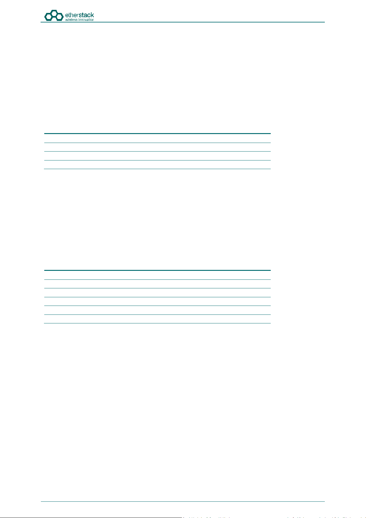
Go Box
1
The GoBox will be in the carry mode with its lid closed and both locking
clamps engaged.
The GoBox will be pre-fitted with a GoBox control module, GoBox radio
modules, GoBox duplexer (in the band/frequency requested at time of
order), 28W power amplifier and dual hot swappable battery module.
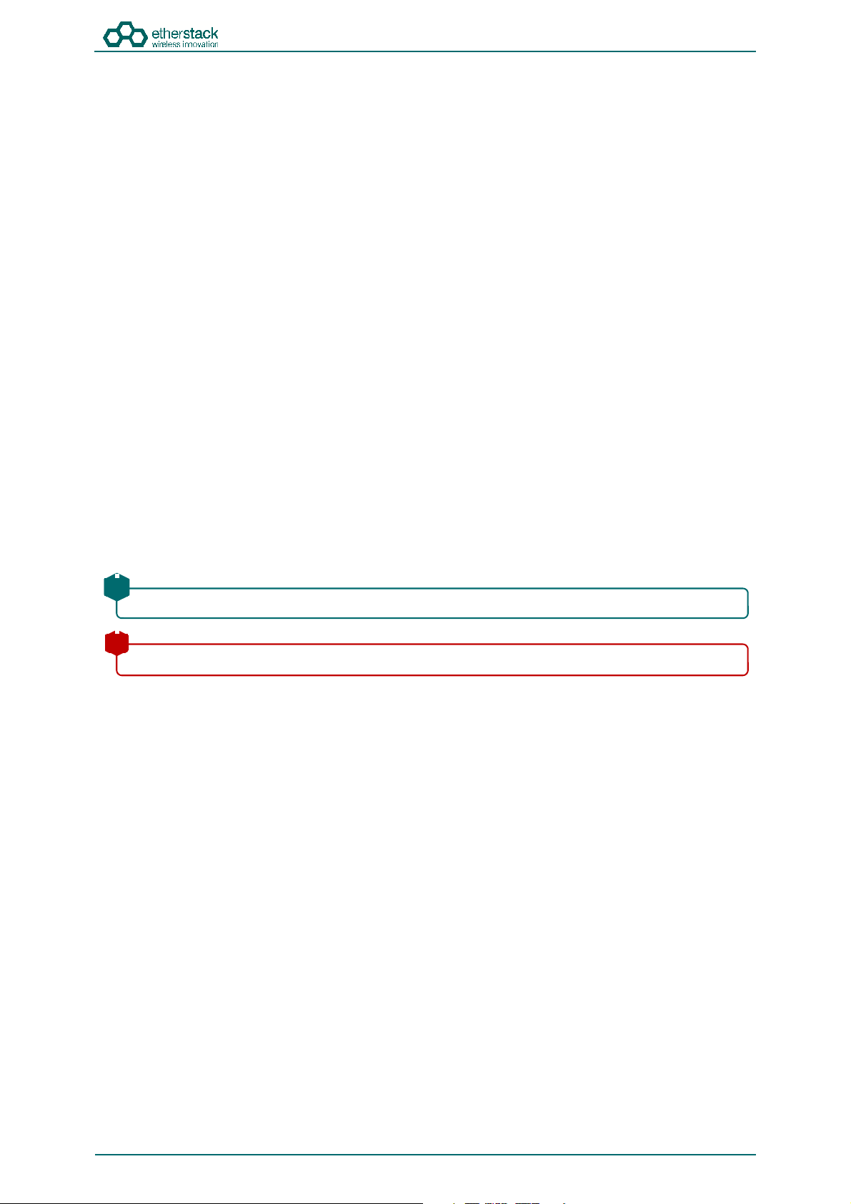
AC Power Cable
The AC power cable will have a standard AC power plug for your country
of operation (requested at time of order) on one end and will have an
IP67 rated coupling socket for connection to the GoBox on the other.
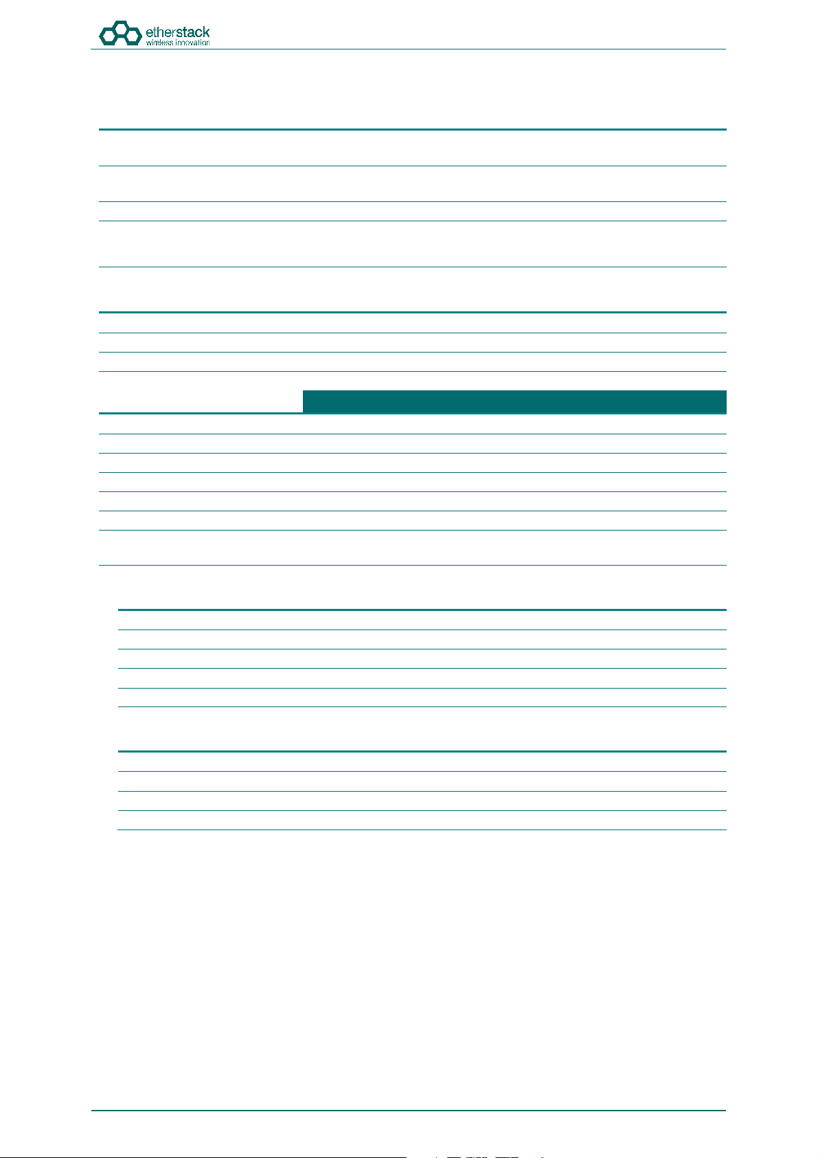
DC Power Cable
The DC power cable will be pre stripped for connection to standard
telecommunications grade power supplies on one end and will have an
IP67 rated coupling socket for connection to the GoBox on the other.
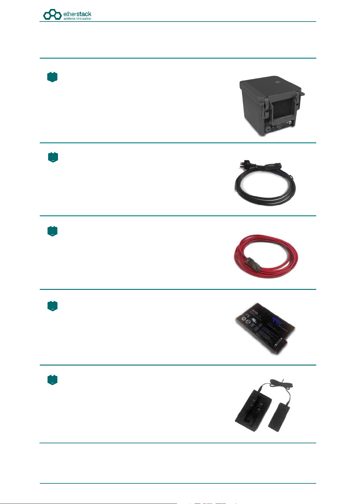
2 x Lithium Ion Rechargeable Batteries
Each battery will require a full charge prior to first use.
It is recommended that any additional batteries be sourced through an
authorised reseller.
Lithium Ion Battery Recharger (Optional Accessory)
An external battery charger is available as an option.
Doc ID: ES1002-UM02-v504
Copyright © 2019 Etherstack
Page 11 of 60
Page 14
2.2 Overview
SFFR-6 User Manual
Getting Started
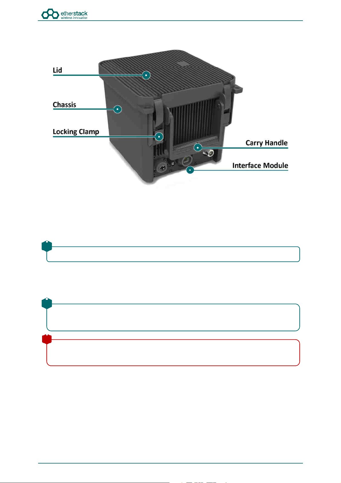
2.2.1 Locking Clamps
The GoBox has two locking clamps on either side of the carry handle to lock the lid firmly against the chassis.
To disengage the locking clamps, place your finger behind the clamps and pull away and up towards the lid. Lift the curved
section of the locking clamp up and out of the channel in the top of the lid and repeat for the other clamp to release the
GoBox lid.
!
Both locking clamps must be fully engaged to ensure a correct seal.
2.2.2 Lid
The GoBox lid has been designed to provide a seal to prevent dust and water from entering the GoBox when the locking
clamps are fully engaged.
!
Once the GoBox has been programmed, the lid only needs to be opened to turn the GoBox on when powered
under batteries. The lid does not need to be closed during operation however it is recommended to be closed
during field use.
!
The lid gasket located around the lid perimeter of the chassis must be kept clean and free of any debris. It should
be inspected before field operation and cleaned or replaced if damaged, otherwise water or dust could penetrate
and damage GoBox electronics.
Doc ID: ES1002-UM02-v504
Copyright © 2019 Etherstack
Page 12 of 60
Page 15
SFFR-6 User Manual
cause some network switches/routers to fail.
including tuning of anten
nas, and appropriate mounting over ground planes.
Getting Started
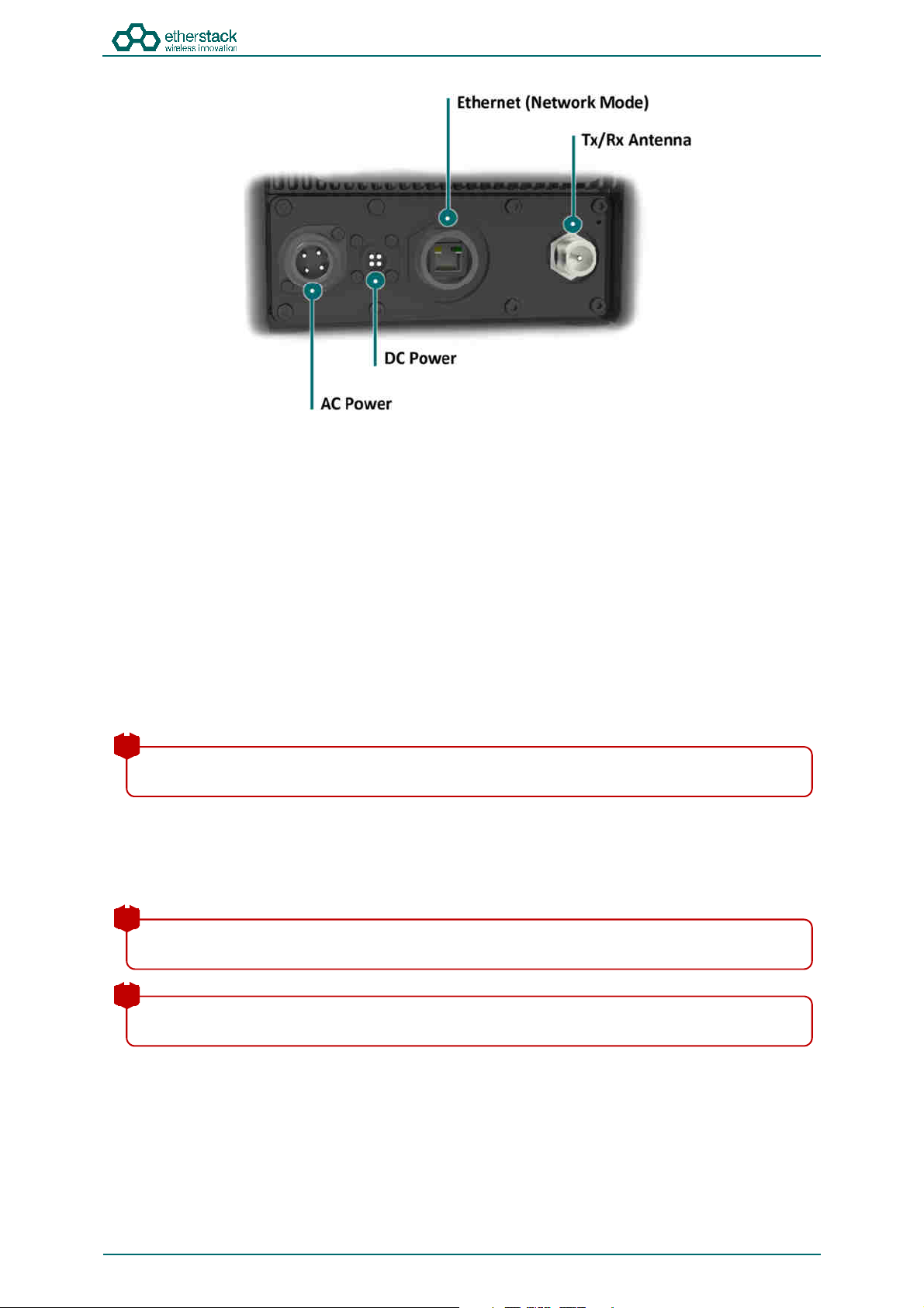
2.2.3 External Interfaces
The External Interfaces will vary based on the options purchased when your GoBox was ordered.
The interface module presents both AC and DC connectors, combined transmit and receive antenna connector or separate
transmit and receive antenna connectors and/or an Ethernet port for use in Network mode.
2.2.3.1 AC Power Connector
The AC Power Connector interfaces to the AC Power Cable. The GoBox supports 100 – 250 VAC.
2.2.3.2 DC Power Connector
The DC Power Connector interfaces to the DC Power Cable. The GoBox supports 10.8 - 15.6 VDC.
2.2.3.3 Ethernet Connector
The Ethernet port is used to access the GoBox’s internal programming menu and/or to connect multiple GoBoxes via
Etherstack’s optional RNC switch.
Attach a standard Ethernet cable to this port with the other end connected directly to a laptop/PC or to other network
equipment. See Section 3.2 below for details on how to program you GoBox.
!
Do not attach an Ethernet cable to both Ethernet ports on the GoBox at the same time to a switch/router as it may
2.2.3.4 Tx/Rx Antenna Connector
The Tx/Rx Antenna Connector is of an N-Type connector and is to be connected to 3rd party antennas. For details of
approved transmit antenna types, refer to the section Approved Transmit Antennas.
! !! !
!
To achieve optimum performance, antennas should be setup according to antenna manufacture specifications,
!
Refer to the safety guidelines in the section Human Exposure to Radio Waves.
Doc ID: ES1002-UM02-v504
Copyright © 2019 Etherstack
Page 13 of 60
Page 16
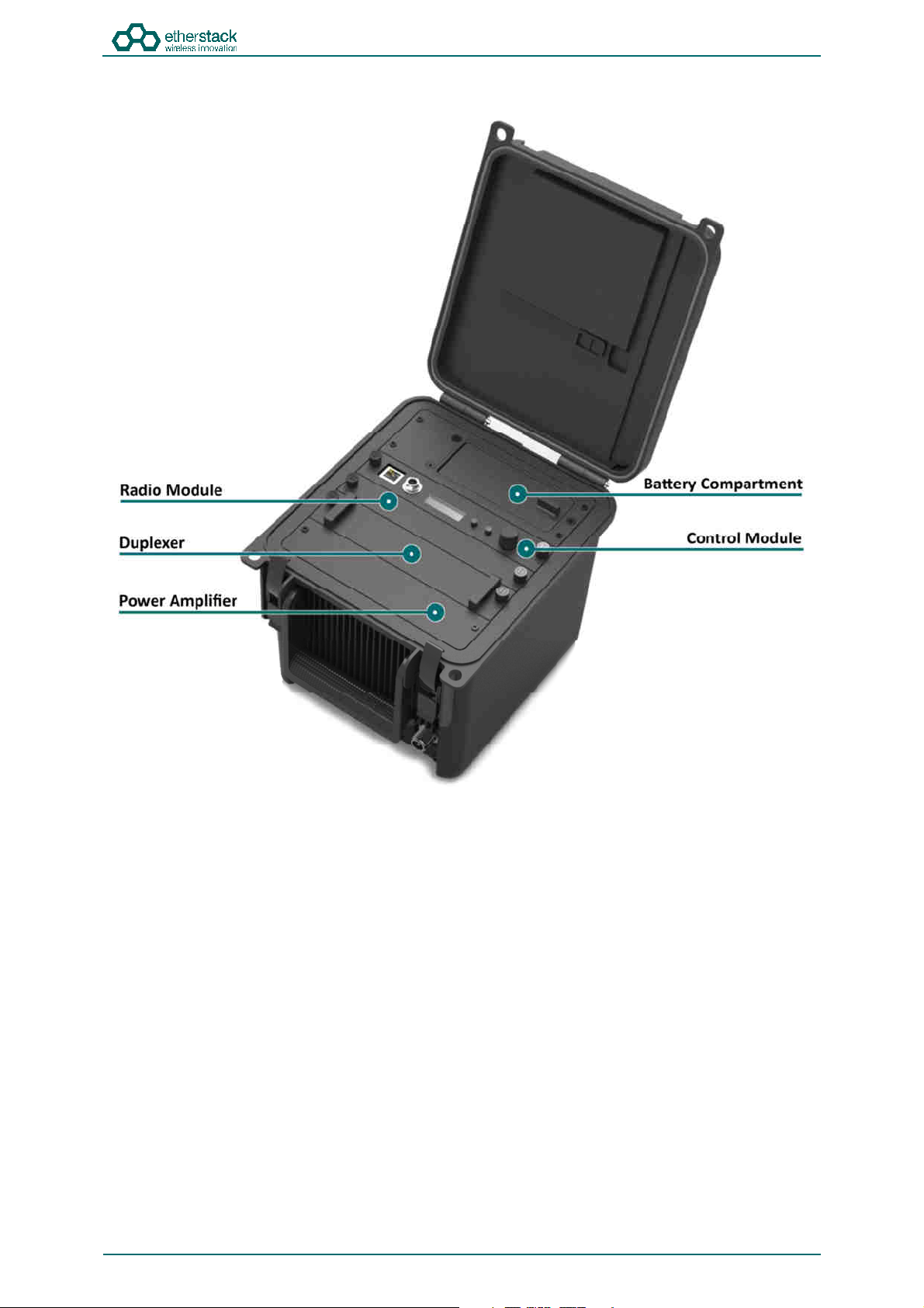
2.2.4 Internal Modules
SFFR-6 User Manual
Getting Started
2.2.5 Battery Compartment
The battery compartment supports two lithium ion batteries and while only one battery is required to operate the GoBox it
is recommended to install two batteries to maximise run time when no AC or DC power is connected.
To open the battery compartment, turn the locking dial on the battery compartment 90 degrees counter clockwise and pull
up to access the battery compartment. To lock the battery compartment, lower the battery compartment lid and turn the
dial 90 degrees clockwise.
Each battery supplied will have a small nylon tag attached to the battery so it can be easily removed when installed in the
GoBox Battery Compartment.
Each battery also has a battery charge status indicator that can be activated by pressing the small button located on the
corner of the battery.
The battery compartment has also been designed to allow battery hot swapping to quickly replace an exhausted battery
source without the need to turn the GoBox off.
The battery compartment has also been designed to recharge batteries when an external power source is applied. Battery
charge and charging state is explained under the control module section below.
Doc ID: ES1002-UM02-v504
Copyright © 2019 Etherstack
Page 14 of 60
Page 17
cause some network
switches/routers to fail.
2.2.6 Control Module
SFFR-6 User Manual
Getting Started
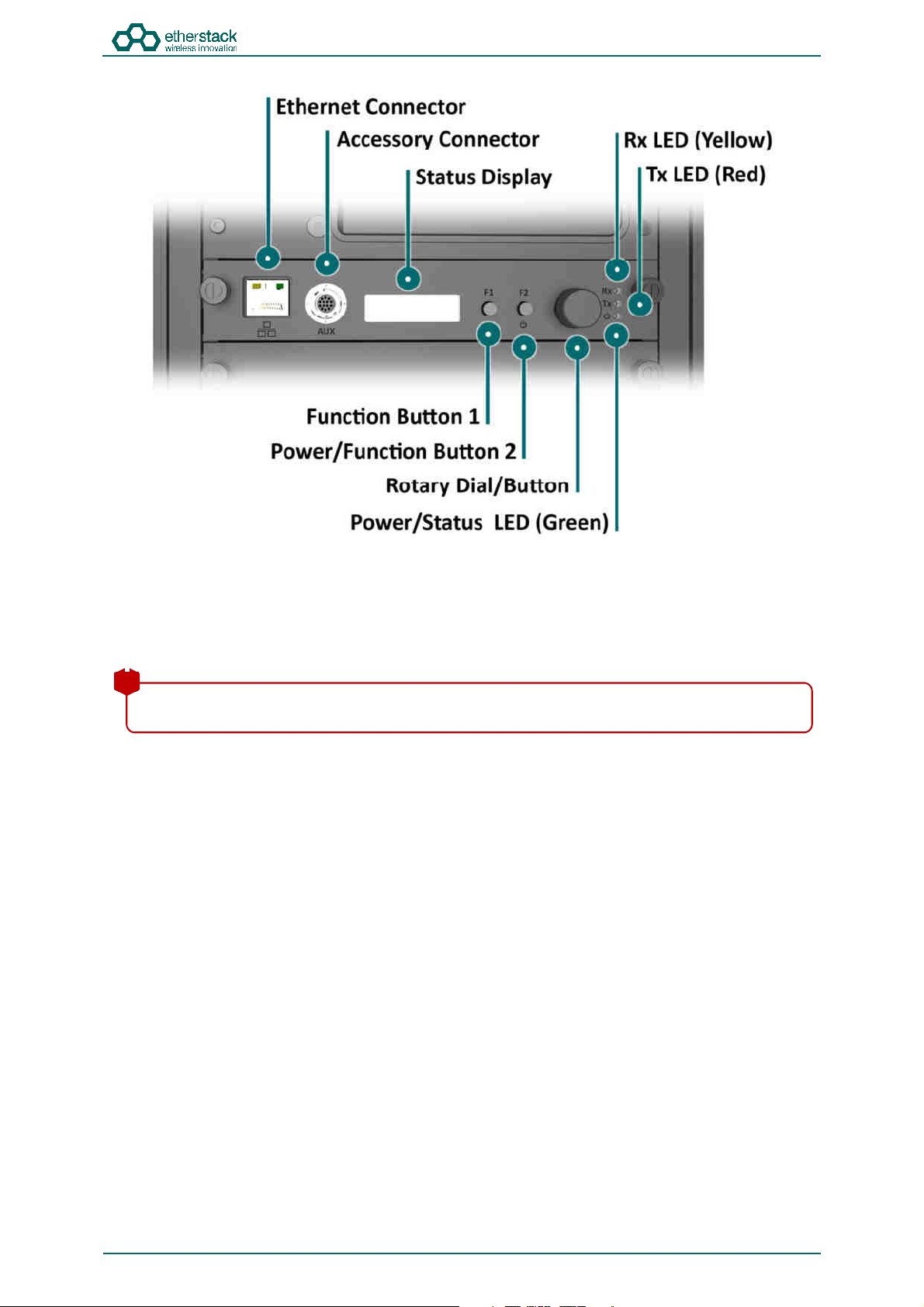
2.2.6.1 Ethernet Connector
The Ethernet port is used to access the GoBox’s internal programming menu and/or to connect multiple GoBoxes via
Etherstack’s optional RNC switch.
Attach a standard Ethernet cable to this port with the other end connected directly to a laptop/PC or to other network
equipment. See Section 3.2 below for details on how to program you GoBox.
!
Do not attach an Ethernet cable to both Ethernet ports on the GoBox at the same time to a switch/router as it may
2.2.6.2 Accessory Connector
The accessory connector is used to connect a local speaker microphone or short range wireless speaker microphone or
headset for operation with the GoBox.
For further information on available accessories please contact your authorised distributor.
Doc ID: ES1002-UM02-v504
Copyright © 2019 Etherstack
Page 15 of 60
Page 18

SFFR-6 User Manual
Getting Started
2.2.6.3 Status Display
The status display shows the currently selected operational profile or other status messages, the power level of each
battery, the status of the on-board battery charger and external power source mode if AC and/or DC power is connected.
The status display’s backlight turns on for several seconds whenever a button or rotary dial is rotated/pressed, so the
display can be more easily viewed if external lighting conditions are poor.
!
The backlight is on a timeout to ensure it is not left on and otherwise drain the batteries unnecessarily.
!
The backlight can be turned off before the timeout period by pressing any of the buttons or the front panel.
!
The intensity of the backlight can be modified to maintain covertness during night use.
2.2.6.4 Function Button 1
Pressing and holding down Function Button 1 turns off the display and LEDs. This normally occurs when the lid is closed
and is designed to save power.
2.2.6.5 Power/Function Button 2
Pressing and holding down Function Button 2 for several seconds will toggle the power status of the GoBox.
!
The power button must be held down for several seconds to avoid accidental power on/off scenarios.
2.2.6.6 Rotary Dial/Button
The rotary dial is used to quickly select different operational profiles.
On pressing the rotary dial, the status window backlight will automatically illuminate until the button is pressed again or
the backlight times out. You can turn the dial to select any of the available and pre-configured profiles when the rotary dial
is pressed.
Once a profile has been found, releasing the rotary dial push button will commence a reconfiguration of the GoBox. During
this time the power/status LED will flash green, indicating a reconfiguration is in progress. When the power/status LED
turns steady green, the GoBox is ready for operation.
!
To avoid accidental profile changes, the rotary dial must be pressed during rotation.
2.2.6.7 Rx LED
On receiving a carrier on the frequency the GoBox is programmed for, the yellow Rx LED will illuminate. Depending on the
operational profile, the received signal has to meet additional conditions before it is repeated.
2.2.6.8 Tx LED
The red Tx LED will illuminate to indicate that the GoBox is transmitting. This can be a locally received and repeated signal,
or when a networked profile is active, a signal forwarded from another GoBox or remote source such as a console or a
subscriber located near a fixed base station site.
2.2.6.9 Power/Status LED
On power-up, the GoBox will perform a series of self-tests to ensure all elements are operational. During this time the
power/status LED will flash green to indicate that power is on but the GoBox is not yet operational. Once the LED turns a
steady green, the GoBox is ready for use.
Doc ID: ES1002-UM02-v504
Copyright © 2019 Etherstack
Page 16 of 60
Page 19

SFFR-6 User Manual
configured, the power/status LED will continue to flash, indicating it is in
the programming state.
external power sources disconnected before removing the duplexer module.
performance may be impacted.
Getting Started
!
The GoBox when first unpacked will not have any operational profiles to execute. Until the GoBox has been
2.2.7 Radio Module
The radio module houses two high performance radio transmitters and receivers. These modules are specific to either the
VHF or UHF bands and will be pre fitted based on the band of the GoBox ordered.
!
The GoBox radio modules have been designed to run at high temperatures in order to support the power output
and high duty cycles typical of a heavy use repeater/base station. Care must be taken if the GoBox has been
running for several hours supporting a large volume of calls. The front panel of the radio module can exceed 50oC.
2.2.8 Duplexer
The GoBox will be fitted with a duplexer when the single antenna interface is fitted. The duplexer module will be tuned to
the centre frequencies requested at the time of order to maximise RF performance.
Additional duplexers in the same band can be ordered and swapped within minutes. Additionally the GoBox can auto sense
the installed duplexer and select the correct operational profile without any user interaction.
!
The duplexer may become hot during operation, particularly at high output power or high duty cycles. Care must
be taken if the GoBox has been running for several hours supporting a large volume of calls. The front panel of the
duplexer module can exceed 50oC.
!
The duplexer is not hot swappable. You must ensure the GoBox is powered down, batteries removed and all
To change the duplexer, ensure the GoBox is turned off and all power sources removed. Remove the duplexer, by turning
the locking screws counter clockwise until the duplexer module can be lift up and out of the GoBox.
When installing a duplexer, take care to ensure that the duplexer is fully inserted. To avoid damaging the module, the
GoBox or the locking screws, do not apply excessive downward force. Alternate between pushing the module in and
turning the locking screws clockwise.
If the GoBox is fitted with separate Rx and Tx antenna connectors (option), a bypass module will be fitted in place of the
duplexer module.
2.2.9 Power Amplifier
The GoBox will be fitted with a power amplifier specific to the band selected.
!
Power amplifiers are not recommended to be swapped and used in GoBoxes operating in another band as
!
The GoBox power amplifier has been designed to run at high temperatures in order to support the power output
and high duty cycles typical of a heavy use repeater/base station. Care must be taken if the GoBox has been running
for several hours supporting a large volume of calls. The chassis areas located near the handle can get hot. This
includes the heat sink and the top of the case near the front edge.
Doc ID: ES1002-UM02-v504
Copyright © 2019 Etherstack
Page 17 of 60
Page 20

3 Configuration
SFFR-6 User Manual
Page 21

SFFR-6 User Manual
network allowing easy transfer of profiles from one GoBox to another.
5.
Restore the configuration to other GoBoxes as required.
Configuration
3.1 Before you begin
3.1.1 About GoBox Configuration
The GoBox stores its configuration in a file that can be downloaded via the programming interface for the purposes of
backup and centralized management.
For users that maintain several GoBoxes, the configuration data can be shared and it is recommended that a single
configuration be used to simplify GoBox administration.
!
If your GoBox is ever damaged or you purchase additional units, your configuration backup can be easily used to
program a new GoBox within minutes using the Restore feature.
3.1.2 About Operational Profiles
To use your GoBox you need to program at least one operational profile which can then be assigned to a duplexer for auto
selection on power-up.
Up to 100 operational profiles can be pre-loaded into the GoBox. Each operational profile contains all information
necessary to configure the GoBox.
Profiles can then be selected and activated by pressing and turning the rotary dial on the GoBox control interface to select
and activate that profile.
!
Make sure you press and hold the rotary dial down when turning to select a new profile.
!
Operational profiles form part of the configuration file and as such can be backed up and restored over the
!
To setup multiple GoBoxes, we recommend using the following process on a single GoBox:
1. Assign a duplexer tag to each duplexer. Where multiple duplexers share the same frequency, you can
assign the same tag
2. Add operational profiles
3. Set the start-up profile for each duplexer
4. Backup the configuration
3.1.3 About Duplexer Group Tags
A duplexer tag can be programmed into a duplexer and then associated to an operational profile to essentially link the
operational profile with the duplexer.
The GoBox will only display operational profiles whose duplexer group tag field has been set to the same tag group as what
is programmed in the duplexer.
!
If an operational profile uses the All tag, the profile will always be visible in the GoBox control panel via the rotary
dial despite what duplexer is fitted, however the profiles frequency may not be supported by the currently
installed duplexer so care must be taken.
Additionally, an operational profile can be assigned as the start-up profile for when the GoBox powers on with a newly
installed duplexer. This feature allows duplexers to be easily moved around GoBoxes in the same band and provided the
configuration files are identical, the GoBox will automatically select the correct operational profile without requiring any
user intervention.
Doc ID: ES1002-UM02-v504
Copyright © 2019 Etherstack
Page 19 of 60
Page 22

SFFR-6 User Manual
Configuration
3.1.4 What you need to program and test your GoBox
3.1.4.1 Laptop or PC with an Ethernet Interface
The GoBox does not require any external programming application to be installed on your laptop/PC and does not require
a special programming cable.
A laptop or PC with a web browser and standard Ethernet cable is all that will be required to configure the GoBox. Once
configured the laptop is no longer required for GoBox operation.
3.1.4.2 Mobile/Portable Radios
Mobile and/or portable radios will be required to be programmed for the duplexer frequencies and other supported
operational parameters such as NACs configured in the GoBox.
!
A simple way to test GoBox operation is to PTT on a correctly programmed mobile/portable radio. If correctly
programmed, the GoBox Rx and Tx LEDs will illuminate.
3.2 Connecting to your GoBox configuration interface
Once your GoBox has been connected via an Ethernet cable using the Ethernet port on the control module to your
laptop/PC or network you will be able to:
View battery presence and charging status
View details of the installed duplexer
Read and write a tag to the duplexer
Create, edit and delete operational profiles
Backup and restore a GoBox configuration
Ensure the GoBox is connected, powered on and connected via Ethernet to your PC/laptop either directly or via a network.
Open your web browser and type the following http://172.16.10.1/
3.2.1 Direct Connection
If the PC/laptop and GoBox are connected directly, i.e. without a network between them, the PC should be configured as
follows:
IP Address: Any valid IP address in the range 172.16.0.1 thru 172.16.255.254, except 172.16.10.1
Subnet Mask: 255.255.0.0
!
The user is responsible for selecting an IP address which does not conflict with other networked equipment, if any
such equipment shares the network segment with the GoBox and PC/laptop.
3.2.2 Connection via a Network
If the PC/laptop is connected to the GoBox via a network, i.e. the PC does not have an address in the 172.16.x.x subnet:
The network to which the GoBox is directly attached should be configured as above.
Additionally, the GoBox expects a gateway capable of routing IP traffic to the PC/laptop at the address
172.16.1.254.
!
Some corporate IT policies may prevent accessing this subnet from your laptop/PC either directly or across your
network. Please contact your local IT support team if you have trouble accessing the GoBox configuration interface.
Doc ID: ES1002-UM02-v504
Copyright © 2019 Etherstack
Page 20 of 60
Page 23

SFFR-6 User Manual
Configuration
The configuration page above will display showing a navigation pane on the left and a content pane on the right.
!
If you see this page you have successfully connected to the GoBox configuration page. If you cannot see this page
contact your IT support department to check your IP configuration.
Doc ID: ES1002-UM02-v504
Copyright © 2019 Etherstack
Page 21 of 60
Page 24

SFFR-6 User Manual
displayed on the form in red.
form.
3.3 Managing Operational Profiles
GoBox profiles are managed under the Profiles heading in the navigation pane. The types of profiles which can be
configured depend on the installed options.
!
If the user enters an invalid value in any form field, the GoBox will reject the profile, and the reason will be
!
Hovering over any form field name that has a dotted underline will display a popup tip to assist completing the
3.3.1 Adding a P25 Conventional Repeating Profile
3.3.1.1 Standalone Mode
Configuration
To create a new P25 Conventional Standalone Repeat Profile, click the P25 Conventional menu item in the navigation pane
and click on + Add Profile button on the content pane.
The following fields will be required to be completed.
The fields are described in detail below in section 3.3.4.
Once the form has been completed, press the Save button to save the profile or Cancel to abort the operation.
Doc ID: ES1002-UM02-v504
Profile Name
Duplexer Group Tag
Rx P25 Type
Rx Frequency
Rx NAC (if the Rx P25 Type is Normal or Selective)
Rx/Tx Talkgroup (if the Rx P25 Type is Selective)
Tx Frequency
Tx NAC (if the Rx P25 Type is Normal or Selective)
Tx Power
Tx Hang Time
Copyright © 2019 Etherstack
Page 22 of 60
Page 25

!
Once Save is pressed and all fields contain valid values, the profile is written to the GoBox.
3.3.1.2 Networked Mode
SFFR-6 User Manual
Configuration
To create a new P25 Conventional Networked Repeat Profile, click the P25 Networked menu item in the navigation pane
and click on + Add Profile button on the content pane.
The following fields will be required to be completed.
Profile Name
Duplexer Group Tag
Rx P25 Type
Rx Frequency
Rx NAC (if Rx P25 Type is Normal or Selective)
Rx/Tx Talkgroup (if Rx P25 Type is Selective)
Tx Frequency
Tx NAC
Tx Power
Tx Hang Time
Network (reference to a Network configuration, see section 4.5.6)
Network Type
For RNC Network Type the following fields are required:
Site ID
Site Subscriber ID
Network Group Address (WACN ID, System ID, Group ID)
For DFSI Network Type the following fields are required:
DFSI Control Port
DFSI Voice Port
The fields are described in detail below in section 3.3.4.
Once the form has been completed, press the Save button to save the profile or Cancel to abort the operation.
!
Once Save is pressed and all fields contain valid values, the profile is written to the GoBox.
Doc ID: ES1002-UM02-v504
Copyright © 2019 Etherstack
Page 23 of 60
Page 26

!
Once a P25 Networked profile is selected, the IP address of the GoBox Web Interface will change to the new IP
address. To re-connect to the GoBox Web Interface at http://172.16.10.1 turn the rotary dial on the control
interface until “Standby” is displayed in the Status Window.
3.3.2 Adding an Analog Conventional Repeating Profile
3.3.2.1 Standalone Mode
SFFR-6 User Manual
Configuration
To create a new Analog Conventional Profile, click the Analog Conventional menu item in the navigation pane and click on
+ Add Profile button on the content pane.
The following fields will be required to be completed.
Profile Name
Duplexer Group Tag
Rx Frequency
Rx Subaudible
Rx RSSI
Tx Frequency
Tx Subaudible
Tx Power
Tx Hang Time
The fields are described in detail below in section 3.3.4.
Once the form has been completed, press the Save button to save the profile or Cancel to abort the operation.
!
Once Save is pressed and all fields contain valid values, the profile is written to the GoBox.
Doc ID: ES1002-UM02-v504
Copyright © 2019 Etherstack
Page 24 of 60
Page 27

3.3.2.2 Networked Mode
SFFR-6 User Manual
Configuration
To create a new Analog Networked Profile, click the Analog Networked menu item in the navigation pane and click on +
Add Profile button on the content pane.
The following fields will be required to be completed.
Profile Name
Duplexer Group Tag
Rx Frequency
Rx Subaudible
Rx RSSI
Tx Frequency
Tx Subaudible
Tx Power
Tx Hang Time
Network (reference to a Network setup, see section 4.5.6)
Network Type
For RNC Network Type the following fields are required:
Site ID
Site Subscriber ID
Network Group Address (WACN ID, System ID, Group ID)
P25 Network Format
For DFSI Network Type the following fields are required:
DFSI Control Port
DFSI Voice Port
The fields are described in detail below in section 3.3.4.
Once the form has been completed, press the Save button to save the profile or Cancel to abort the operation.
!
Once Save is pressed and all fields contain valid values, the profile is written to the GoBox.
!
Once an Analog Networked profile is selected, the IP address of the GoBox Web Interface will change to the new IP
address. To re-connect to the GoBox Web Interface at http://172.16.10.1 turn the rotary dial on the control
interface until “Standby” is displayed in the Status Window.
Doc ID: ES1002-UM02-v504
Copyright © 2019 Etherstack
Page 25 of 60
Page 28

SFFR-6 User Manual
Configuration
3.3.3 Adding a Mixed Mode Conventional Repeating Profile
3.3.3.1 Standalone Mixed Mode
To create a new Mixed Mode Standalone Profile, click the Mixed Mode Conventional menu item in the navigation pane
and click on + Add Profile button on the content pane.
The fields required are a combination of both P25 and Analog profiles, enabling both voice formats to be repeated
depending upon the transmitting subscriber unit.
3.3.3.2 Network Mixed Mode
To create a new Mixed Mode Networked Profile, click the Mixed Mode Networked menu item in the navigation pane and
click on + Add Profile button on the content pane.
The fields required are a combination of both P25 and Analog profiles, enabling both voice formats to be repeated locally
and via the network connection.
Doc ID: ES1002-UM02-v504
Copyright © 2019 Etherstack
Page 26 of 60
Page 29

3.3.4 Profile Field Descriptions
3.3.4.1 Common Profile Fields
Field Description
Profile Name
Duplexer Group Tag
Rx Frequency
Tx Frequency
Tx Power The transmit power in Watts to use for this operational profile.
Create a unique profile name that will appear in the status window of the GoBox control interface. This
name is what your operational profile will be called.
The Profile Name is limited to 8 characters and may only include letters, numbers or a hyphen '-'. The
names “Standby” and “None” cannot be used.
If duplexer group tags have been created, you can select a duplexer group to associate this profile with.
Selecting a specific duplexer tag means this profile will only be available on the GoBox control interface if
the corresponding duplexer is installed.
If duplexer group tags have not been created, you can select All and then edit the profile once duplexer
group tags have been created. Selecting All means this profile option will always be available to select on
the GoBox control interface regardless of what duplexer is installed.
Once an operational profile is associated with a duplexer group tag, it may also be chosen as the start-up
profile for a newly installed duplexer.
This should be set to the desired centre receive frequency. The installed duplexer must be calibrated to this
frequency to ensure optimal RF performance.
This should be set to the desired centre transmit frequency. The installed duplexer must be calibrated to
this frequency to ensure optimal RF performance.
SFFR-6 User Manual
Configuration
3.3.4.2 P25 Profile Fields
Field Description
Rx P25 Type
Monitor All detected P25 signals will be repeated with the same NAC as was received.
Normal Only P25 signals with the specified Rx NAC code will be repeated/forwarded.
Selective
Rx NAC
Tx NAC
0x293 ($293) the default NAC
0xf7e ($F7E)
0xf7f ($F7F)
Talkgroup The GoBox may be configured to only repeat P25 signals matching a certain Talkgroup Id.
Tx Hang Time
The Rx P25 Type field indicates the level of filtering the GoBox will apply to a received signal before
repeating the signal.
Only P25 signals with the specified Rx NAC code and Talkgroup Id will be
repeated/forwarded.
The NAC is a feature similar to CTCSS or DCS for analog radios. Repeaters can be programmed to only
repeat P25 signalling when receiving the correct NAC.
NACs are programmed as a three-hexadecimal-digit code that is transmitted along with the digital signal
being transmitted.
Three of the possible NACs have special functions
a repeater set for this NAC will repeat P25 signalling on any decoded signal
received
a repeater set for this NAC will allow all incoming decoded signals and the
repeater transmitter will retransmit the received NAC
Allowed values are 1 to 65535 inclusive.
The GoBox may be configured with an additional duration that is included at the end of every voice
transmission. In P25 this transmission consists of additional terminator data units that enable subscribers
to check that their uplink reached the repeater and was rebroadcast successfully.
Allowed values are 0 (no hang time) to 30000 milliseconds.
3.3.4.3 Analog Profile Fields
Field Description
Rx Subaudible
Tx Subaudible
None
CTCSS Use CTCSS tone signalling. Select the tone frequency from the option field.
Doc ID: ES1002-UM02-v504
The Rx subaudible field sets the subaudible tone signalling which a received signal must contain in order to
be repeated.
The Tx subaudible field sets the tone signalling for the transmitted signal.
All detected analog signals, subject to the Rx RSSI, will be repeated.
Transmitted signals carry no tone signalling.
Copyright © 2019 Etherstack
Page 27 of 60
Page 30

Field Description
CDCSS
Rx RSSI Minimum receive signal strength, measured in approximate equivalent SINAD dB units.
Tx Hang Time
The GoBox may be configured with an additional duration that is included at the end of every voice
transmission. In Analog this transmission consists of additional carrier, with no subaudible content, that
enables subscribers to check that their uplink reached the repeater and was rebroadcast successfully.
Allowed values are 0 (no hang time) to 30000 milliseconds.
Use DCS digital subaudible signalling. Two options fields are available: the
first allows selecting inverted DCS, the second selects the code. All codes are
shown in octal notation.
Networked Profile Fields
Field Description
Network
Network Type This option is used to select the type of network connection. It must be one of RNC or DFSI.
P25 Network Format
This option references a Network configuration that has already been created in the Administration ->
Network Configurations section. Details of the IP Address, Subnet Mask, Default Gateway and VPN options
are all part of the Network configuration that can be re-used by multiple network profiles. This prevents
the need to enter common networking parameters multiple times.
See section 4.5.6 for details on how to create network configuration that can be selected by one or more
network profiles.
A RNC connection can be used to establish multi-site GoBox functionality or other ISSI interconnections. A
DFSI is used to connect to a DFSI Host, usually a console user.
This option is only available for Analog Network profiles and is used to select the type of network traffic
used for Analog voice.
If checked, Analog voice from the air interface will be encoded into P25 IMBE on the network. Likewise P25
voice from the network will be decoded into Analog on the air interface.
This option enables the GoBox to bridge Analog subscriber units with P25 network users.
SFFR-6 User Manual
Configuration
RNC Networked Profile Fields
Field Description
Site ID
Site Subscriber ID
WACN ID P25 Wide Area Communications Network ID.
System ID P25 System ID.
Group ID P25 Network Talkgroup ID.
The Site ID indicates the identity of the P25 site and is inserted into over-the-air traffic. The Site ID must be
unique within an RFSS when the GoBox is used in Network mode.
The Site ID is limited to values between 0 and 255 (decimal).
The site subscriber ID is used to register and affiliate with the RNC to allow multisite conventional
repeating. The value should be unique and homed to an RFSS.
Allowed values are hexadecimal (00000 to FFFFF)
Allowed values are hexadecimal (000 to FFF)
Allowed values are hexadecimal (0000 to FFFF)
DFSI Networked Profile Fields
Field Description
DFSI Control Port The local UDP port to listen for incoming DFSI Host control messaging.
The default value for DFSI is port 7000
DFSI Voice Port The local UDP port to use for voice communication with the DFSI Host
Doc ID: ES1002-UM02-v504
Copyright © 2019 Etherstack
Page 28 of 60
Page 31

3.3.5 Setting the Operational Profile Order
SFFR-6 User Manual
Configuration
If you have created a large number of profiles, it may be useful to set the order in which they appear on the GoBox control
interface.
To change the display order, select the page All Profiles from the Profiles section of the navigation pane, and click Change
Order.
The stored profiles are initially all shown in the left column, and can be sorted there either in the current order or
alphabetically by name. Move them to the right column in the desired order, using the following operations:
1. Select one or more profiles by clicking and sweeping up and down within either column.
2. Select all profiles in the left column by clicking on Select All.
3. Move selected profiles from the left to the right column by clicking the right-arrow button. The profiles will be
inserted in the new ordering at the cursor (the row with the dashed border).
4. Move the cursor up and down in the right column by clicking on the up-arrow or down-arrow buttons.
5. Move selected profiles from the right column back to the left column by clicking the left-arrow button. The
profiles will be shown according to the selected sorting criterion.
6. Once all profiles are in the right column in the desired order, click Save. Alternatively click Cancel to return to
the profile list without changing the order.
Doc ID: ES1002-UM02-v504
Copyright © 2019 Etherstack
Page 29 of 60
Page 32

SFFR-6 User Manual
Configuration
3.4 Managing Duplexers
3.4.1 Writing a Duplexer Group Tag
Before the GoBox will recognise a duplexer and allow operational profiles to be associated with it, you must write a
duplexer group tag to the duplexer’s internal memory. To do this use the following steps:
Click on the Duplexer menu item on the navigation pane and press the Edit button on the content pane to show the Edit
Duplexer form.
The following fields will be required to be completed.
Field Description
Tag
Once the form has been completed, press the Save button to write to the duplexer or Cancel to abort the operation.
A unique name for this duplexer group. Allowed characters are A-Z, a-z, 0-9 and '-'. Up to 8 characters can
be entered. The tag “All” is reserved and cannot be used.
!
Writing to the duplexer will take several seconds. If the page does not update automatically after a short time, it
may be necessary to click the Refresh button to verify the tag has been written.
Doc ID: ES1002-UM02-v504
Copyright © 2019 Etherstack
Page 30 of 60
Page 33

SFFR-6 User Manual
!
Configuration
3.4.2 Setting the start-up profile for a Duplexer
To define different start-up profiles for different duplexers use the following steps:
!
At least one operational profile is required.
Click on the Duplexer Group Tags menu item on the navigation pane and press the + Add Duplexer Group Tag button on
the content pane to show the Add Duplexer Group Tag form.
The following fields will be required to be completed.
Field Description
Duplexer Group Tag
Comment (Optional) An optional comment describing this duplexer group tag.
Rx Freq The receive frequency of the duplexer group
Tx Freq The transmit frequency of the duplexer group
Start-up Profile The operational profile to be selected when the GoBox powers on
The last active profile (before the GoBox was shut down) takes precedence over the Start-up Profile. However, if
this profile is not compatible with the currently installed duplexer, the Start-up profile will be used..
A unique name for this duplexer group. Allowed characters are A-Z, a-z, 0-9 and '-'. Up to 8 characters can
be entered. The name “All” cannot be used.
Doc ID: ES1002-UM02-v504
Copyright © 2019 Etherstack
Page 31 of 60
Page 34

SFFR-6 User Manual
Create or edit each operational profile, and link it to a specific duplexer by setting the Duplexer Group Tag field.
Configuration
Back in the Duplexer Group Tag menu item, select a start-up profile for each duplexer.
Doc ID: ES1002-UM02-v504
Copyright © 2019 Etherstack
Page 32 of 60
Page 35

SFFR-6 User Manual
4 Using the GoBox
Page 36

SFFR-6 User Manual
accidental power
-
on/off.
Using the GoBox
4.1 Turning your GoBox On
The GoBox will automatically turn on when AC or DC power is first applied or a battery is inserted with sufficient charge.
If a power source has already been connected and the GoBox was previously turned off via the GoBox Power Button,
pressing and holding down the Power button will turn the GoBox on.
!
The power button must be held down for several seconds to turn the GoBox on and off. This is a feature to avoid
During the GoBox’s power-on self-test, the status window backlight and all control panel LEDs will turn on briefly to
indicate these subsystems are fully operational.
During the GoBox’s power-on self-test, the Power LED will flash to indicate that power is supplied but the GoBox is not
ready for use. During this time, the status window shows a progress bar to provide an approximate indication of the
remaining time.
After approximately 30 seconds, the Power LED will turn solid indicating that the GoBox is ready for use if a suitable
operational profile can be found otherwise the Power LED will continue to flash and the word Standby displayed in the
GoBox status window.
!
If the GoBox cannot find a profile matching the installed duplexer during start-up, it displays “Standby” in the status
window. You will need to attach a laptop/PC to the GoBox and follow the steps in section 3.4 to address the issue.
If operational profiles have been programmed into the GoBox, and a valid operational profile found, this operational
profile will be selected and the GoBox will be ready for operation, indicated by a solid green power/status LED.
4.2 Selecting an Operational Profile
4.2.1 Front Panel
Once the GoBox has been programmed with operational profiles, you can change the operating profile by pressing the
rotary dial and turning to select the required profile. Releasing the button activates the currently displayed profile.
During profile changes, the GoBox will perform a soft reset, indicated by a flashing Power LED. When the Power LED
returns to a solid state the operational profile will have been loaded and the GoBox is ready for use.
If the selected profile is networked, status indicators on the bottom row of the display will indicate the network status. A
blinking “WWW” or “VPN” icon indicates that the GoBox is awaiting network connectivity for clear and encrypted
connections, respectively. Once connected, the status icon will turn solid and an adjacent “RNC” icon will start blinking.
When the GoBox successfully registers with the RNC, the “RNC” icon will turn solid and the GoBox shall be fully network
operational.
!
The GoBox will always power up using the last active profile if it is compatible with the installed duplexer.
Otherwise, it will use the duplexer’s default profile, if configured.
4.2.2 Web Configuration Interface
To activate an operational profile remotely, navigate to the All Profiles page or to one of the pages showing details of one
type of profile, such as the P25 Conventional page, find the row with the profile you want to activate, and click on the
Select action in that row.
Doc ID: ES1002-UM02-v504
Copyright © 2019 Etherstack
Page 34 of 60
Page 37

SFFR-6 User Manual
Using the GoBox
The profiles which can be selected this way are the same as on the GoBox front panel. I.e. only profiles which have a
duplexer group tag of All or match the installed duplexer have a Select action.
4.3 Stopping Repeater Operation
The GoBox can be returned to a standby state whereby it does not repeat according to any operational profile, but can be
programmed using the web interface.
4.3.1 Front Panel
Press the rotary dial, turn it while holding the dial down until “Standby” appears in the display, and release the dial.
Doc ID: ES1002-UM02-v504
Copyright © 2019 Etherstack
Page 35 of 60
Page 38

SFFR-6 User Manual
An external battery charger is also available.
Using the GoBox
The GoBox will continue to display “Standby” and the power/status LED will blink green, until an operational profile is
selected.
4.3.2 Web Interface
Select Active Profile under the heading Status of the navigation pane, and click on the Stop button.
4.4 Checking GoBox Status
The GoBox displays several indicators in the status window such as power source, battery state and active operational
profile and if a laptop/PC is connected additional status information can be viewed.
4.4.1 Status Window
4.4.1.1 Checking Battery Status
Two rectangles will appear in the top right hand corner of the status window to indicate if any of the batteries are detected
in the battery compartment.
A solid rectangle indicates a battery is inserted and is fully charged. A partially filled rectangle indicates the remaining
battery charge. When a battery has no charge remaining it will be represented as an empty rectangle.
The GoBox has a built in battery charger. When AC or DC power is available, any batteries detected in the GoBox will be
charged. This will be indicated by a scrolling battery charge image.
!
Doc ID: ES1002-UM02-v504
Copyright © 2019 Etherstack
Page 36 of 60
Page 39

SFFR-6 User Manual
Both power sources can be connected at the same time.
Using the GoBox
4.4.1.2 Checking External Power Source
The letters AC and/or DC will appear in the bottom right hand corner of the status window to indicate if any external
power source is detected.
!
Doc ID: ES1002-UM02-v504
Copyright © 2019 Etherstack
Page 37 of 60
Page 40

SFFR-6 User Manual
Using the GoBox
4.4.1.3 Checking the current operational profile
The GoBox will display the current operational mode in the status window after power up.
If the GoBox displays “Standby” in the status window, the GoBox is in programming mode and awaiting a connection from
a laptop or PC otherwise the GoBox will display the current operational profile.
4.4.2 Web configuration interface
4.4.2.1 Checking Battery Status
To access this page, click on the Battery menu item on the navigation pane.
The battery status page will show if a battery is installed, each batteries current charge percentage and if the internal
GoBox battery charger is active.
!
To update the page with the latest information press the Refresh button.
!
The battery charger will only operate when an AC or DC power source is applied and will automatically turn off to
protect the battery once full charge has been reached.
Doc ID: ES1002-UM02-v504
Copyright © 2019 Etherstack
Page 38 of 60
Page 41

4.4.2.2 Checking Duplexer Status
To access this page, click on the Duplexer menu item on the navigation pane.
SFFR-6 User Manual
Using the GoBox
The duplexer status page will show the duplexer serial number, receive centre frequency, transmit centre frequency, date
last calibrated and the duplexer group tag used to link a duplexer to a start-up operational profile.
!
To update the page with the latest information, press the Refresh button.
4.4.3 Checking Active Profile
To access this page, click on the Active Profile menu item on the navigation pane.
Doc ID: ES1002-UM02-v504
Copyright © 2019 Etherstack
Page 39 of 60
Page 42

SFFR-6 User Manual
Using the GoBox
The active profile status page will show:
Active Profile: The active profile name. This will match what is shown on the GoBox status window.
Status:
Loading whilst the profile is being loaded
Operational once the profile is ready
For network profiles additional status information is available depending upon the type of connection:
RNC: Displays whether or not the GoBox has successfully connected to the RNC.
Not Connected if the GoBox is not connected to the RNC
Registering if the GoBox is attempting to connect to the RNC
Registration Failed if the GoBox can communicate with the RNC but cannot register
Affiliation Failed if the GoBox can communicate with the RNC but cannot affiliate to the network group
Registered if connected and registered with RNC successfully
DFSI: Displays whether or not a DFSI Host has successfully established a connection to the GoBox.
Not Connected if no DFSI Host has connected
Connected if successfully connected to a DFSI Host, along with the DFSI Host IP Address and Host UDP Port.
When the GoBox is used with a VPN to establish a secure connection to a network, additional status information is
available,
Certificate: displays the file name of the VPN client certificate used by the current profile
Status: displays current VPN status which is one of
Disconnected if no VPN can be established
Connecting whilst in the process of trying to connect to the VPN server
Connected once a successful connected has been established
Need Password if the VPN profile requires a password but has not been entered yet
Invalid Password if the VPN profile requires a password but the provided password returned an error
Password: allows the input of VPN password information. If the VPN profile does not require a password this field
is greyed out.
!
To update the page with the latest information press the Refresh button.
When a profile is active, clicking Stop will deactivate it.
Doc ID: ES1002-UM02-v504
Copyright © 2019 Etherstack
Page 40 of 60
Page 43

This will overwrite all profiles and duplexer group
tags currently stored on the GoBox.
4.5 Administration
4.5.1 Backing up GoBox Configuration Data
SFFR-6 User Manual
Using the GoBox
To back-up your GoBox configuration to your local computer, click the Backup menu item on the left hand navigation pane
and click on the Download GoBox Profiles button in the content pane.
A specially constructed zip file containing all GoBox profiles will be downloaded to the Download folder of your local
computer. This file should be archived and stored in a safe place.
This configuration file can be used to restore the configuration on any GoBox and/or program future GoBoxes.
4.5.2 Restoring GoBox Configuration Data from a Backup
To restore a GoBox configuration, click the Restore menu item on the left hand navigation pane and click on the Restore
button in the content pane.
A file browser will then be displayed where you can select a previously backed up configuration file.
!
Doc ID: ES1002-UM02-v504
Copyright © 2019 Etherstack
Page 41 of 60
Page 44

This will clear all profiles and duplexer group tags currently stored on the GoBox.
4.5.3 Downloading GoBox Log Files
SFFR-6 User Manual
Using the GoBox
To download the GoBox log files to your local computer, click the Logs menu item on the left hand navigation pane and
click on the Download button in the content pane.
A zip file containing all GoBox profiles will be downloaded to the Download folder of your local computer. When reporting
an issue with the GoBox, support staff may request a copy of the log files to help diagnose the issue.
4.5.4 Clearing the GoBox Configuration from memory
To clear all GoBox profile and duplexer group tag information, and restore the brightness setting to its original state, click
the Factory Reset menu item on the left hand navigation pane and click on the Factory Reset button in the content pane.
!
!
Duplexer tags stored on duplexers are not affected by a factory reset.
Doc ID: ES1002-UM02-v504
Copyright © 2019 Etherstack
Page 42 of 60
Page 45

The brightness of the network traffic LEDs on the control module cannot be changed.
4.5.5 Settings
!
Changes made on the Settings page will apply globally to all GoBox operational profiles.
SFFR-6 User Manual
Using the GoBox
4.5.5.1 GoBox Name
The GoBox can be assigned a name to help identify it when accessed via the web interface. The name will appear in the top
right corner of all pages visited on the web interface. The user may adopt any naming convention and uniqueness is not
enforced.
4.5.5.2 Web Access Controls
An administrator (the GoBoxUser account) may restrict actions that can be performed via the web interface by users who
have not logged in (anonymous users). These actions include viewing (or backing up) the GoBox configuration and log files,
adding/editing profiles and settings, selecting the active profile, and updating the GoBox firmware. If the administrator is
accidentally locked out of the web interface, please contact support.
4.5.5.3 Adjusting the LED and LCD Backlight Brightness
To change the brightness of the Rx/Tx and Status LEDs and LCD Backlight, select Settings from the navigation pane.
The brightness can be set in 5 levels, corresponding approximately to off, 3%, 10%, 30% and 100%. Select a brightness level
and click Save.
The brightness will be set to the highest level after a power cycle or factory reset.
!
Updating and saving the brightness will take several seconds. If the page does not update automatically after a
short time, it may be necessary to click the Refresh button.
!
Doc ID: ES1002-UM02-v504
Copyright © 2019 Etherstack
Page 43 of 60
Page 46

SFFR-6 User Manual
selected. During this time the VPN may report failure to connect.
Using the GoBox
4.5.5.4 NTP and DNS Servers
When using the GoBox in VPN mode, the network time must align with the VPN server time. In order to ensure time
accuracy, the GoBox requires one or more NTP servers which are designated Primary and Secondary. Enter the hostnames
or IP addresses of reliable NTP servers in these fields, e.g. time.nist.gov.
A DNS server is also required to resolve the NTP server hostnames. The DNS server must be entered as an IP address, e.g.
8.8.8.8.
!
Updating and syncing network time may take a number of minutes after a profile using a network has been
4.5.5.5 Programmable Time-Out Timer
The GoBox can automatically shut down the transmit path after a maximum call duration. This prevents battery drain or an
occupied transmit path when a subscriber unit is holding down the PTT button, either intentionally or accidentally.
Once this duration has been reached, the transmit path is returned to an idle state. There is no lock-out period and any
subsequent transmission may use the transmit path, however if the local uplink remains busy then it may not allow other
users to talk until the offending subscriber unit releases their PTT button.
Allowed values are 0 (no time-out) to 300 seconds.
!
The default value for this is 60 seconds, and unless modified, users should be aware that a long PTT transmission
may end prematurely.
4.5.5.6 Repeat FNE-addressed Data
FNE-addressed (unit ID = 0) data packets are typically not repeated over-the-air by the GoBox. This behaviour may be
changed by enabling this setting, which forces all inbound data packets to be repeated, no matter the destination address.
Doc ID: ES1002-UM02-v504
Copyright © 2019 Etherstack
Page 44 of 60
Page 47

SFFR-6 User Manual
Using the GoBox
4.5.6 Network Configurations
When an operational profile is using Network mode, it references a number of common settings that are defined by the
Network Configurations Administrative page. This page provides settings including the IP Address, Subnet Mask and
Default Gateway that can be combined into a network configuration. Additionally, VPN settings are included as part of the
network setup to allow a number of similar profiles to re-use the same network details without requiring manual re-entry
of these fields.
To view the Network Configurations, click the Network Configurations menu item on the left hand navigation pane which
will display a list of current network configurations in the content panel.
There is always a Default network configuration which the Standby profile is associated with. This network configuration
cannot be modified or deleted. This allows administrators the ability to always connect to the Standby profile with a direct
Ethernet connection.
To add a new network configuration click the Add Configuration button.
Doc ID: ES1002-UM02-v504
Copyright © 2019 Etherstack
Page 45 of 60
Page 48

SFFR-6 User Manual
4.5.6.1 Network Configuration Fields
Field Description
Network Name Create a unique network name that will be referenced during creation of any networked profile.
The Network Name is limited to 8 characters and may only include letters, numbers or a hyphen '-'.
VPN Certificate A reference to a VPN configuration. Upload VPN certificates from the VPN certificate tab.
If no VPN is to be used select None.
IP Address
Subnet mask The subnet mask the GoBox will use when this operational profile is selected.
Default gateway The default gateway the GoBox will use when this operational profile is selected.
RNC IP Address
RFSS ID P25 Radio Frequency Sub-System ID.
System ID P25 System ID.
Group ID P25 Network Talkgroup ID.
High Latency / Unreliable
Link
Several “Advanced Options” are also available by clicking on the “+” to expand the form:
IP Address the GoBox will use when this operational profile is used. The GoBox will reconfigure its network
interface and IP address to this value when selected.
The static IP Address of the RNC that the GoBox will register with and will be used to perform multi-site
repeating.
Allowed values are hexadecimal (000 to FFF)
Allowed values are hexadecimal (0000 to FFFF)
When checked, the GoBox will perform PTT arbitration locally instead of needing a round-trip to the RNC to
enforce the talking party.
This field can be checked to reduce repeat delay if there is a backhaul link between the GoBox and RNC
that is slow or disconnects often (e.g. satellite).
Using the GoBox
Field Description
Control Traffic DSCP Differentiated Service Code Point for Control Traffic
A classification parameter for network traffic between the GoBox and an RNC or DFSI host. It is used to
provide QoS.
The DSCP must be between 0 and 63.
Voice Traffic DSCP Differentiated Service Code Point for Voice Traffic
RNC Poll Period A SIP Options request will be sent to the RNC at the supplied interval to determine the connection status.
On a metered network connection, this figure can be increased to reduce connection costs associated with
this action.
The poll period must be between 0 and 30 seconds.
Voice Frames Per RTP
Packet
Keep Network Calls Alive
The number of voice frames within each RTP packet sent into the network.
On a metered network connection, this figure can be increased to reduce connection costs.
Valid values are 1, 2, or 3.
When checked, the GoBox will attempt to re-establish the RTP connection associated with a network group
if it is torn down by RNC.
On a metered network connection, disabling this can reduce connection costs if the P25 network regularly
tears down the talk group.
The recommended default is checked.
4.5.6.2 VPN Certificate Management
The GoBox supports using a VPN connection to establish a secure network tunnel between itself and a remote server via
the use of OpenVPN. The GoBox is the VPN client and expects to establish the connection with a VPN server. To view and
add new VPN connections, click on the Network Configurations administrator option and then click the VPN Certificate
Management tab.
Doc ID: ES1002-UM02-v504
Copyright © 2019 Etherstack
Page 46 of 60
Page 49

SFFR-6 User Manual
Using the GoBox
To add a new VPN certificate, click the Choose File button. Your VPN administrator should have provided you with a
filename with the suffix .ovpn which is the format for OpenVPN client certificates and also contains other VPN settings
specific to each client.
Once selected, click the Upload button to copy the file to the GoBox, the new certificate should appear in the certificate
listings and can then be used by network configurations.
Doc ID: ES1002-UM02-v504
Copyright © 2019 Etherstack
Page 47 of 60
Page 50

SFFR-6 User Manual
Using the GoBox
4.5.7 Firmware Versions
The GoBox consists of several hardware and firmware sub systems. Since the behaviour will vary slightly between versions,
it will be necessary to provide details of the installed firmware versions with any problem reports or support queries.
To view the installed versions, select Firmware from the navigation pane. The Firmware Update tab lists the currently
installed firmware versions under the Installed Version column.
The Base Components tab lists components which are not user upgradable but whose versions may be required by
Support.
Doc ID: ES1002-UM02-v504
Copyright © 2019 Etherstack
Page 48 of 60
Page 51

The Features tab lists the options licensed for this GoBox.
SFFR-6 User Manual
Using the GoBox
Doc ID: ES1002-UM02-v504
Copyright © 2019 Etherstack
Page 49 of 60
Page 52

SFFR-6 User Manual
Using the GoBox
4.5.8 Upgrading Firmware
The GoBox supports updating of the firmware components listed on the Firmware Update tab of the Firmware page.
Upgrading the GoBox firmware consists of two steps, which can be done at different times:
1. Uploading a firmware distribution file, which has previously been copied to the PC/laptop, to the GoBox.
2. Installing the firmware.
4.5.8.1 Uploading a Firmware Distribution File
In order to ensure a smooth file transfer, check that the following prerequisites can be met:
1. The GoBox and PC/laptop must be able to maintain a network connection for the duration of the upload. This may
take several minutes if the network link is slow: For the typical size of 4.5MBytes of a firmware distribution file,
and over a relatively slow link of 256kbit/s, the transfer could take 3-4 minutes.
2. If the GoBox is operating with a networked repeating profile, and the PC/laptop connects to the GoBox over the
same link as the call traffic between the GoBox and the RNC, uploading a firmware distribution file may affect the
voice quality. It is recommended to either not upload a firmware distribution file while operating a networked
repeating profile, or connect the PC/laptop directly to the GoBox for the upload, not using the same network
connector of the GoBox as for the link to the RNC.
3. Changing the operating profile of the GoBox during an upload, where either the new or old profile is networked,
may interrupt the upload. This is due to the change of the GoBox’ IP address.
Navigate to Firmware from the navigation pane, and select the tab Distribution File Upload.
Click on Browse... to select a file, then click on Upload to start transferring the file. The page will show some information
about the progress of the upload. At the end of a successful upload, the browser will be redirected to the Firmware
Update tab.
4.5.8.2 Installing Firmware Updates
Before beginning the firmware installation procedure, check that the following conditions are met:
1. The GoBox has sufficient power for the whole procedure, i.e. is either powered with a sufficiently charged battery
or connected to an AC or DC power source. An estimate of the time required for installation is shown before the
process starts. No installation process is expected to take more than about 10 minutes.
2. Repeater operation must be halted while firmware is being installed. Ensure that no radio communications rely on
this GoBox for the needed time.
3. If the GoBox is operating with a networked profile, the GoBox will not automatically deselect this profile, because
doing so may interrupt the network connection between the GoBox and PC/laptop. In this case, manually deselect
the profile before commencing a firmware update, using the rotary dial on the GoBox or the Status -> Active
Profile page of the remote interface.
Doc ID: ES1002-UM02-v504
Copyright © 2019 Etherstack
Page 50 of 60
Page 53

SFFR-6 User Manual
Once a firmware distribution file has been uploaded to the GoBox, its contents are listed alongside the installed
component versions.
Using the GoBox
During a typical firmware update, all components are brought up to date with the versions contained in the uploaded
distribution file. Components which already contain the same firmware version as the available one are skipped. Click on
Apply to proceed.
An estimate of the time required for the update is calculated and shown at this time. To start the installation, click on
Proceed, otherwise click on Cancel.
Doc ID: ES1002-UM02-v504
Copyright © 2019 Etherstack
Page 51 of 60
Page 54

SFFR-6 User Manual
Using the GoBox
A progress screen is shown for the duration of the installation process, and is updated approximately once a second. If the
web interface itself is being updated, progress screen updates may be suspended for up to 20 seconds.
!
If the progress page stops refreshing during an update, e.g. because the network connection was interrupted, or the
user navigates away in the browser, the update will nevertheless continue.
Open http://172.16.10.1/update/progress/ to resume viewing the status of the update.
During an update, the status display on the GoBox will generally show “Updating” and the power/status and Rx LEDs will
flash. Certain upgrade steps may temporarily turn off the status display and LEDs entirely.
Once the installation process has completed, clicking on Close will return to the firmware overview page.
Doc ID: ES1002-UM02-v504
Copyright © 2019 Etherstack
Page 52 of 60
Page 55

SFFR-6 User Manual
5 Troubleshooting
Page 56

SFFR-6 User Manual
Troubleshooting
5.1 Cannot connect to the GoBox web interface
Ensure a functioning Ethernet cable is connected to the GoBox from your PC/Laptop and check the Ethernet activity lights
are on or flashing on the GoBox Ethernet connector.
Ensure that the GoBox LCD displays the "Standby" string. This ensures that the IP address configuration will be set to the
default of 172.16.10.1. If the GoBox does not display "Standby", press and turn the rotary dial until the status window
displays "Standby", then release the dial.
Verify there is network connectivity between your PC/laptop and the GoBox on the 172.16.10.1 subnet. (Request help from
your System Administrator if required.)
5.2 Network Status icon displays REG ERR
The RNC was reachable, but the GoBox could not complete the registration procedure due to a configuration error on the
GoBox or RNC. In this scenario, the GoBox will repeat calls locally, but will not receive from or send calls out onto the
network. Check that the P25 network addresses on the RNC and GoBox match, and that the RNC contains an entry for the
talk group configured on the GoBox. If a change was required on the RNC, the GoBox will periodically retry to register until
it is successful. Otherwise, re-select the profile after the necessary changes are made on the GoBox.
5.3 Network Status icons displays PSWD
The selected profile is trying to connect to a VPN using a certificate that requires a decryption password. To enter the
password, visit the “Active Profile” page on the GoBox web interface. Enter the password in the prompt within the “VPN
Connection” panel and click “Submit”.
5.4 Network Status icon WWW does not turn solid
The GoBox is unable to reach the server hosting the RNC or VPN service. The following should be verified:
the active profile’s Network Configuration is configured with the correct RNC IP address
the network plan permits routing of packets between the GoBox and RNC
the WAN connection is established (e.g. satellite modem)
5.5 Network Status icon VPN does not turn solid
On very high latency links, the VPN service may have trouble establishing a connection, even if there is general network
connectivity. If the GoBox’s system time is out of sync, this may increase the time required to establish a connection. Allow
several minutes for the GoBox to sync to the NTP server. If the GoBox still cannot connect to the VPN service, even after
reselecting the active profile, submit the GoBox logs to support to help determine the cause of the issue.
5.6 Network Status icon RNC does not turn solid
The GoBox cannot connect to the RNC service. Verify that the RNC service is online and that the profile’s network
configuration contains the correct RNC IP address.
5.7 Status window displays Err:Ctrl
Power-cycle the GoBox and if the problem persists turn the GoBox off and remove and reinsert the control module. If the
error still is present when power is reapplied, contact support.
5.8 Status window displays Err:Rad1, Err:Rad2 or Err:Rad12
Doc ID: ES1002-UM02-v504
Copyright © 2019 Etherstack
Page 54 of 60
Page 57

SFFR-6 User Manual
Troubleshooting
Power-cycle the GoBox and if the problem persists turn the GoBox off and remove and reinsert the radio module. If the
error still is present when power is reapplied, contact support.
5.9 There are no profiles to select on the GoBox control panel
You need to have at least one profile programmed in your GoBox and if a duplexer tag is configured, at least one of the
profiles must have the same tag or the tag “All”, otherwise it will be hidden.
Check your operational profiles using the web interface and retry.
Profile selection is also disabled during firmware installation.
5.10 GoBox web interface displays “Template Syntax Error”
The GoBox profile and duplexer information may have become corrupted due to a power or network loss during
configuration.
If this occurs, please either restore your operational profiles from a backup or perform a Factory Reset using the web
interface.
5.11 The LEDs and the LCD backlight do not turn on
Using the Settings page of the web interface, check that the brightness has not been set to “Off”.
5.12 When turning on the GoBox, the LEDs flash rapidly for a second,
and the LCD stays blank
This may occur after an interrupted firmware update attempt (e.g. the GoBox lost power during the installation.)
Wait 30 seconds after powering up, then connect a PC/laptop and attempt to open the web interface. If it is available, go
to the Firmware page and try to repeat the last firmware installation. If the web interface is not accessible, contact an
authorised dealer for support.
Doc ID: ES1002-UM02-v504
Copyright © 2019 Etherstack
Page 55 of 60
Page 58

SFFR-6 User Manual
6 Glossary
Page 59

Term Definition
APCO Association of Public-Safety Communications Officials
AVL Automatic Vehicle Location
DFSI Digital Fixed Station Interface
ISSI Inter Sub-System Interface
MMI Man Machine Interface
NAC Network Access Code
OTAR Over the Air Rekeying
PTT Push-To-Talk
P25 Project 25
RFSS Radio Frequency Sub-System
RNC RFSS Network Controller
SFFR Small Form Factor Repeater
VPN Virtual Private Network
WACN Wide Area Communications Network
SFFR-6 User Manual
Glossary
Doc ID: ES1002-UM02-v504
Copyright © 2019 Etherstack
Page 57 of 60
Page 60

SFFR-6 User Manual
Glossary
Powered By
Asia Pacific Headquarters
Etherstack Pty Ltd
Level 1, 80 Abercrombie Street
Sydney NSW 2008
AUSTRALIA
Ph: +61 2 8399 7500
Fax: +61 2 8399 7507
info.au@etherstack.com
Etherstack Japan
Etherstack Japan
12F Daiwa Jisho Building
74-1 Yamashita-cho Naka-ku
Yokohama Kanagawa 231-0023
JAPAN
Ph: +81 45 342 9050
Fax: +81 45 342 9053
info.jp@etherstack.com
European Headquarters
Etherstack Limited
30-31 Friar Street
Reading, RG1 1DX
UNITED KINGDOM
Ph: +44 20 7734 0200
Fax: +44 20 7437 1505
info.eu@etherstack.com
North American Headquarters
Etherstack Inc
1115 Broadway, 12th Floor
New York, NY 10010
UNITED STATES
Ph: +1 917 661 4110
Fax: +1 212 255 3610
info.na@etherstack.com
Copyright © 2016 Etherstack London Limited and Etherstack under License. All rights reserved.
No part of this publication may be reproduced, transmitted, transcribed, stored in a retrieval system, or translated into any language, in
any form or by any means, electronic, mechanical, photocopying, recording, or otherwise, without prior written permission from
Etherstack London Limited or Etherstack.
All copyright, confidential information, patents, design rights and all other intellectual property rights of whatsoever nature contained
herein are and shall remain the sole and exclusive property of Etherstack London Limited. The information furnished herein is believed to
be accurate and reliable. However, no responsibility is assumed by Etherstack London Limited for its use, or for any infringements of
patents or other rights of third parties resulting from its use.
The name Etherstack London Limited and Etherstack logo are trademarks or registered trademarks of Etherstack London Limited. The
name Etherstack and logo are trademarks or registered trademarks of Etherstack.
All other trademarks are the property of their respective owners.
Doc ID: ES1002-UM02-v504
Copyright © 2019 Etherstack
Page 58 of 60
 Loading...