

Ethernet Direct RUE-111, RUE-113 User Manual
Industrial 10/100BaseTX to
100BaseFX Media Converter
RUE-111 (multimode) RUE-113 (singlemode)
User Manual
Rev. 2.00
15-September-2006

FCC Warning
This Equipment has been tested and found to comply with the limits for a
Class A digital device, pursuant to Part 15 of the FCC rules. These limits
are designed to provide reasonable protection against harmful
interference in a residential installation. This equipment generates, uses
and can radiate radio frequency energy and, if not installed and used in
accordance with the instructions, may cause harmful interference to radio
communications. However, there is no guarantee that interference will not
occur in a particular installation. If this equipment does cause harmful
interference to radio or television reception, which can be determined by
turning the equipment off and on, the user is encouraged to try to correct
the interference by one or more of the following measures:
Reorient or relocate the receiving antenna.
Increase the separation between the equipment and receiver.
Connect the equipment into an outlet on a circuit different from that to
which the receiver is connected.
Consult the dealer or an experienced radio/TV technician for help.

Contents
Introduction.........................................................1
Features................................................................... 1
Package Contents....................................................2
Hardware Description.........................................3
Physical Dimension..................................................3
Front Panel............................................................... 3
Bottom View............................................................. 4
Ports......................................................................... 4
Cabling..................................................................... 6
LED Indicators.......................................................... 7
DIP-switch................................................................ 8
Wiring the Power Inputs......................................... 10
Wiring the Fault Alarm Contact.............................. 11
Mounting Installation ........................................12
DIN-Rail Mounting.................................................. 12
Wall Mount Plate Mounting.................................... 14
Hardware Installation........................................15

Troubleshooting................................................18
Technical Specifications...................................19

Introduction
The Industrial 10/100BaseTX to 100BaseFX Media Converter is a costeffective solution for the converting 10/100Base-TX (Auto MDI/MDIX) to
100Base-FX cabling. It provides two power inputs that can be connected
simultaneously to two DC power sources. If one power input fails, the
other one acts as a backup.
The Industrial 10/100BaseTX to 100BaseFX Media Converter also
provides relay alarm outputs to warn when the port link failure, so the
technician can respond quickly with appropriate emergency operation
procedures.
IP- switches are used to set the operation mode for relay alarm, Fiber
ports, link loss forwarding function, and UTP operation mode.
Features
UTP to Fiber Media converter
Auto Negotiation Speed and Half/Full Duplex
12 to 48VDC power inputs
TX port supports Auto MDI/MDI-X
Relay alarm output for port link failure
IEEE 802.3x flow control support
¾ Flow control on full-duplex
¾ Back pressure on half-duplex
Built-in Link Loss Forwarding Technology
DIN-Rail or wall mountable
DIP-switches to set the operation mode and Link- Lost-Forwarding
function.
Redundant dual DC power Inputs
1
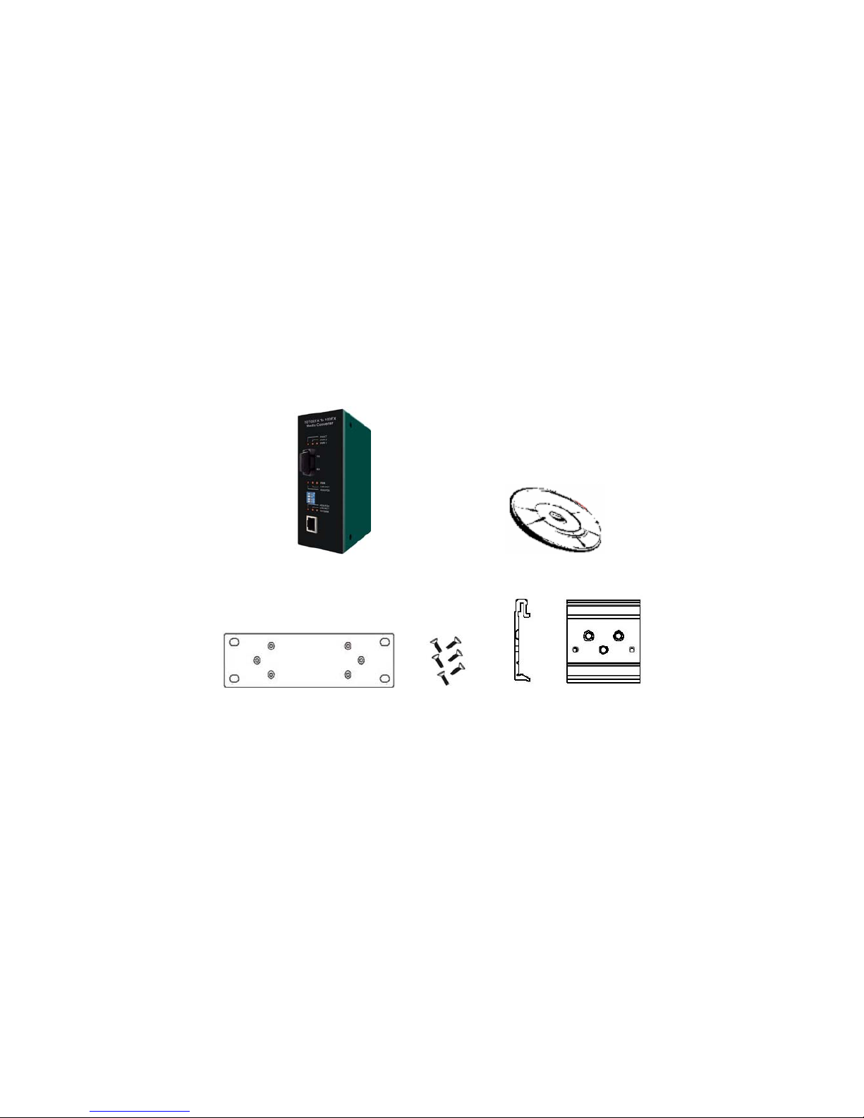
Package Contents
Please refer to the package content list below to verify them against the
checklist.
Industrial 10/100BaseTX to 100BaseFX Media Converter
One DIN-Rail (screwed on the converter)
One wall mount plate and six screws
User manual
Industrial 10/100BaseTX to 100BaseFX User Manual
Media Converter
Wall Mount Plate Screws DIN-Rail
Compare the contents of your industrial media converter with the standard
checklist above. If any item is damaged or missing, please contact your
local dealer for service.
2

Hardware Description
In this paragraph, we will introduce the Industrial media converter’s
hardware spec, port, cabling information, and wiring installation.
Physical Dimension
Industrial 10/100BaseTX to 100BaseFX Media Converter dimensions (W
x H x D) are 54mm x 135mm x 105mm
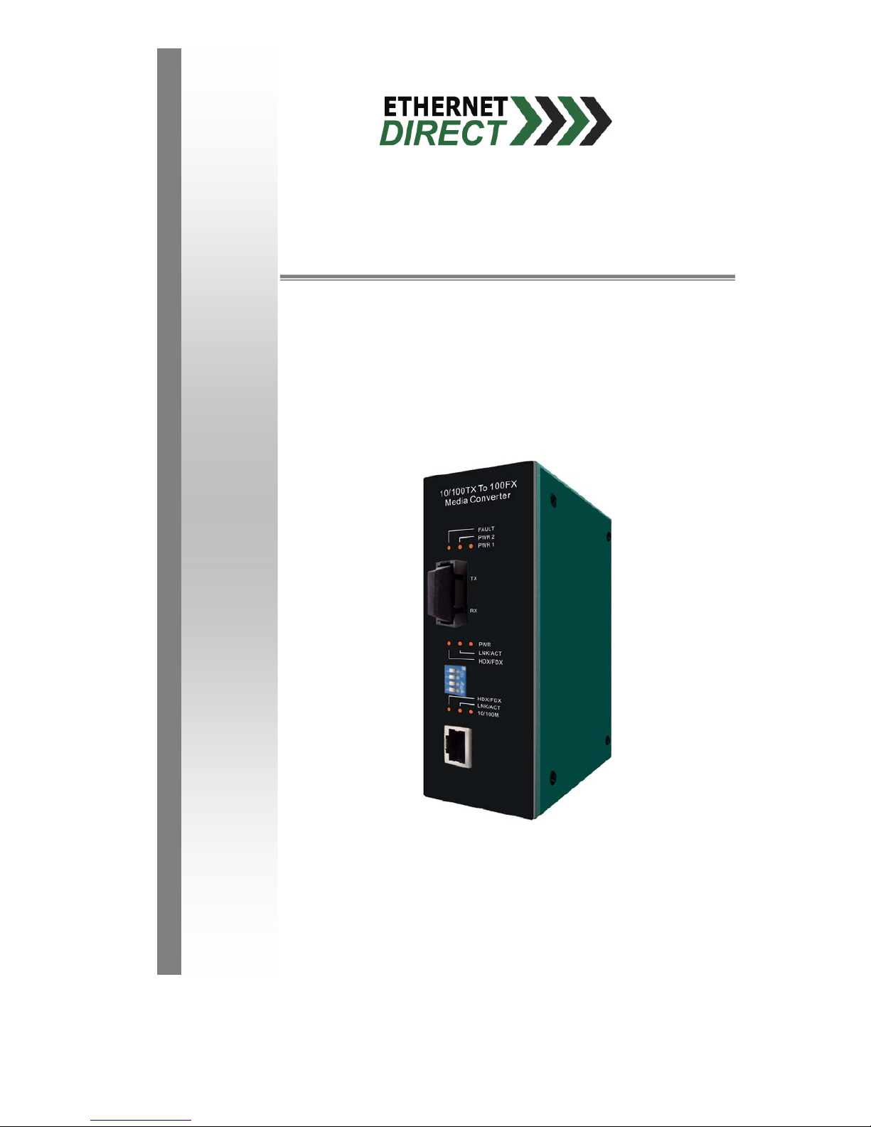
Front Panel
The Front Panel of the Industrial 10/100BaseTX to 100BaseFX Media
Converter is showed below.
LED Indicator
Fiber Port
DIP Switch
UTP Port
Front Panel of the Industrial 10/100BaseTX to 100BaseFX Media Converter
3
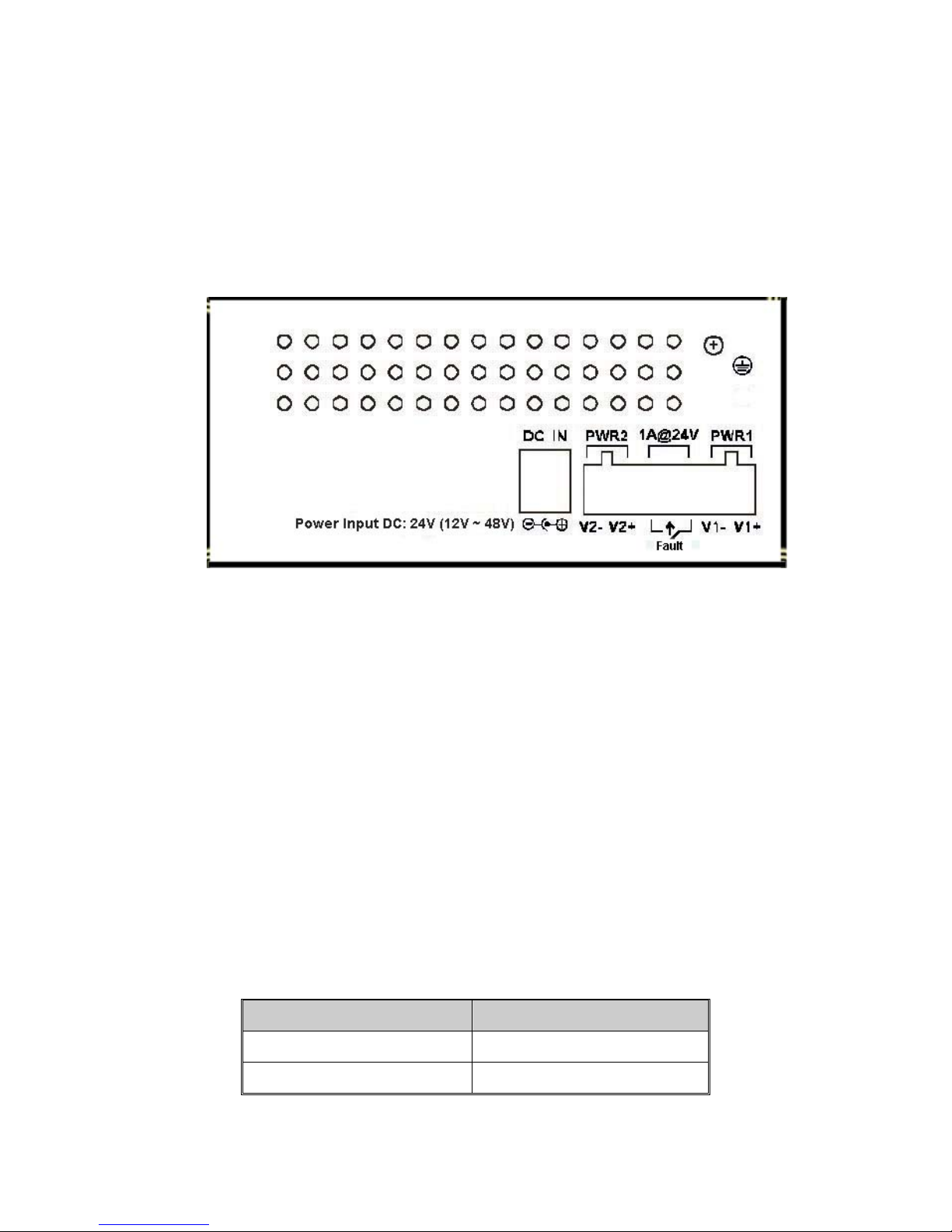
Bottom View
The bottom view of the Industrial 10/100BaseTX to 100BaseFX Media
Converter consists one terminal block connector within two DC power
inputs and one DC IN power jack.
Bottom Panel of Industrial 10/100BaseTX to 100BaseFX Media Converter
Ports
RJ-45 Port
The UTP ports will auto-sense for 10Base-T or 100Base-TX connections.
Auto MDI/MDIX means that you can connect to another Switch or
workstation without changing straight through or crossover cabling. See
the Figure C and C-1 for straight through and crossover cabling
schematic.
RJ-45 Pin Assignments
Pin Number Assignment
1 Tx+
2 Tx-
4
 Loading...