


HMG-838PT
HMG-838EPT
Industrial 8 x 10/100Base-T(X) + 3 x
100/1000Base SFP Gigabit Managed
Ethernet Switch
User’s Manual
(Web Configuration)
V1.3
11-06-2017

Husky Series Industrial Ethernet Switch Solutions
HMG-838PT & HMG-838EPT Industrial Gigabit Managed Ethernet Switch
User’s Manual (Web Configuration)
Copyright Notice
Copyright © 2017 Ethernet Direct Corp.
All rights reserved.
Reproduction in any form or by any means without Ethernet Direct prior written permission is prohibited.

Table of Contents
Chapter 1 Web Configuration Home ................................................................................................................................................1
1-1 Entering Web Configuration..............................................................................................................................................1
1-2 Port State..........................................................................................................................................................................1
1-3 Refresh
1-4 Save .................................................................................................................................................................................2
1-5 Help
1-6 Logout
Chapter 2 Sy
2-1 System Information Configuration.....................................................................................................................................1
2-2 System Information
2-3 System IP .........................................................................................................................................................................2
2-4 System IP
2-5 System NTP......................................................................................................................................................................4
2-6 System Time.....................................................................................................................................................................5
2-7 System Log.......................................................................................................................................................................5
2-8 Detailed Log
2-9 System CPU Load
2-10 System SMTP...................................................................................................................................................................7
Chapter 3 Green Ethernet .................................................................................................................................................................1
3-1 Green Ethernet LED .........................................................................................................................................................1
3-2 Green Ethernet Configuration
3-3 Green Ethernet S
Chapter 4 Port
4-1 Ports Configuration
4-2 Ports S
4-3 Ports Traffic O
4-4 Ports QoS S
4-5 Ports QCL
4-6 Ports Detailed S
4-7 UTP Cable Diagnostics
4-8 Ports SFP
Chapter 5 Security
5-1 Switch ...............................................................................................................................................................................1
5-1.1 User
5-1.2 Privilege Levels
5-1.3 Auth Method
5-1.4 SSH ....................................................................................................................................................................3
5-1.5 HTTPS................................................................................................................................................................4
5-1.6 Access Management ..........................................................................................................................................5
5-1.6.1 Access Management Configuration
5-1.6.2 Access Management S
5-1.7 SNMP
5-1.7.1 SNMP System Configuration
5-1.7.2 Alarm Configuration
5-1.7.3 SNMPv3 Communit
5-1.7.4 SNMPv3 User Configuration
5-1.7.5 SNMPv3 Group Configuration
.............................................................................................................................................................................2
..................................................................................................................................................................................2
...............................................................................................................................................................................2
stem ..............................................................................................................................................................................1
...........................................................................................................................................................1
Status ..............................................................................................................................................................3
......................................................................................................................................................................6
............................................................................................................................................................6
...........................................................................................................................................1
tatus ......................................................................................................................................................3
s ..................................................................................................................................................................................1
...........................................................................................................................................................1
tate ........................................................................................................................................................................2
verview.......................................................................................................................................................3
tatistics ..........................................................................................................................................................3
Status ..............................................................................................................................................................4
tatistics ....................................................................................................................................................4
.....................................................................................................................................................6
.........................................................................................................................................................................7
.............................................................................................................................................................................1
....................................................................................................................................................................1
..................................................................................................................................................2
.......................................................................................................................................................3
....................................................................................................................5
tatistics...........................................................................................................................5
.................................................................................................................................................................6
..............................................................................................................................6
............................................................................................................................................6
y Configuration....................................................................................................................9
............................................................................................................................10
..........................................................................................................................11

5-1.7.6 SNMPv3 View Configuration ............................................................................................................................11
5-1.7.7 SNMPv3 Access Configuration
5-1.8 RMON ..............................................................................................................................................................13
5-1.8.1 RMON Statistics Configuration
5-1.8.2 RMON History Configuration
5-1.8.3 RMON Alarm Configuration
5-1.8.4 RMON Event Configuration
5-1.8.5 RMON Statistics Overvie
5-1.8.6 RMON History
5-1.8.7 RMON Alarm Overvie
5-1.8.8 RMON Event Overvie
5-2 Network
5-2.1 Port Securit
5-2.1.1 Limit Control
5-2.1.2 Switch S
5-2.1.3 Port S
5-2.1.4 Link Detection
5-2.2 NAS ..................................................................................................................................................................22
5-2.2.1 Configuration
5-2.2.2 Switch S
5-2.2.3 Port S
5-2.3 ACL ..................................................................................................................................................................26
5-2.3.1 Port
5-2.3.2 Rate Limiters
5-2.3.3 Access Control List
5-2.3.4 ACL
5-2.4 DHCP
5-2.4.1 DHCP Server S
5-2.4.2 DHCP Server Binding IP
5-2.4.3 DHCP Server Declined IP
5-2.4.4 DHCP Server Mode Configur
5-2.4.5 DHCP Server Excluded IP
5-2.4.6 DHCP Server Pool Configuration
5-2.4.7 Snooping Configuration
5-2.4.8 Snooping T
5-2.4.9 Relay Configuration
5-2.4.10 Relay
5-2.5 IP Source Guard
5-2.5.1 IP Source Guard Configuration.........................................................................................................................40
5-2.5.2 Static Table
5-2.5.3 Dynamic T
5-2.6 ARP Inspection
5-2.6.1 Port Configuration.............................................................................................................................................42
5-2.6.2 VLAN Mode Configuration
5-2.6.3 Static Table
5-2.6.4 Dynamic T
5-3 RADIUS
5-3.1 Configuration
..........................................................................................................................................................................17
tatus........................................................................................................................................................20
tatistics....................................................................................................................................................26
s .................................................................................................................................................................27
Status........................................................................................................................................................32
...............................................................................................................................................................33
Statistics .................................................................................................................................................39
..........................................................................................................................................................................44
Overview ..................................................................................................................................16
w ....................................................................................................................................16
w ....................................................................................................................................17
y.....................................................................................................................................................17
.....................................................................................................................................................17
tatus....................................................................................................................................................19
...................................................................................................................................................20
....................................................................................................................................................22
tatus....................................................................................................................................................25
....................................................................................................................................................28
...........................................................................................................................................28
tatistics.....................................................................................................................................33
able.................................................................................................................................................39
..........................................................................................................................................39
...............................................................................................................................................40
.......................................................................................................................................................41
able..................................................................................................................................................42
.................................................................................................................................................42
.......................................................................................................................................................44
able Status.......................................................................................................................................44
....................................................................................................................................................45
.........................................................................................................................12
.........................................................................................................................13
............................................................................................................................13
..............................................................................................................................13
..............................................................................................................................14
w ...............................................................................................................................15
..................................................................................................................................34
................................................................................................................................34
ation....................................................................................................................35
Configuration..........................................................................................................35
.....................................................................................................................36
....................................................................................................................................38
................................................................................................................................43

5-3.2 RADIUS Overview............................................................................................................................................46
5-3.3 RADIUS Det
5-4 TACACS+ .......................................................................................................................................................................49
Chapter 6 Aggregation ......................................................................................................................................................................1
6-1 Static.................................................................................................................................................................................1
6-2 LACP
Chapter 7 Redundancy......................................................................................................................................................................1
7-1 Direct-Ring........................................................................................................................................................................1
7-2 Loop Protection
7-3 Spanning T
7-4 MEP................................................................................................................................................................................15
7-5 ERPS (ITU-T
Chapter 8 IPMC Profile
8-1 Profile Table ......................................................................................................................................................................1
8-2 Address Entry
Chapter 9 MVR
9-1 Configuration
9-2 MVR Statistics
9-3 MVR Channel Group
9-4 MVR SFM Info
Chapter 10 IPMC
10-1 IGMP Snooping ................................................................................................................................................................1
10-2 MLD Snooping
................................................................................................................................................................................2
6-2.1 Port Configuration...............................................................................................................................................2
6-2.2 System S
6-2.3 Port S
6-2.4 Port S
7-1.1 Configuration
7-1.2 Status
7-2.1 Configuration
7-2.2 Status
ree...................................................................................................................................................................7
7-3.1 Bridge Settings
7-3.2 MSTI Mapping
7-3.3 MSTI Priorities
7-3.4 CIST Port
7-3.5 MSTI Port
7-3.6 Bridge S
7-3.7 Port S
7-3.8 Port S
G.8032) .....................................................................................................................................................22
......................................................................................................................................................................1
...................................................................................................................................................................................1
....................................................................................................................................................................1
................................................................................................................................................................................1
10-1.1 Basic Configuration
10-1.2 VLAN Configuration
10-1.3 Port Filtering Profile
10-1.4 Status
10-1.5 Groups Information
10-1.6 IPv4 SFM Infor
10-2.1 Basic Configuration
10-2.2 VLAN Configuration
10-2.3 Port Filtering Profile
10-2.4 Status
ails................................................................................................................................................46
tatus ....................................................................................................................................................3
tatus..........................................................................................................................................................3
tatistics......................................................................................................................................................4
......................................................................................................................................................1
.................................................................................................................................................................5
.................................................................................................................................................................5
......................................................................................................................................................6
.................................................................................................................................................................6
...................................................................................................................................................7
....................................................................................................................................................9
..................................................................................................................................................10
s........................................................................................................................................................10
s .......................................................................................................................................................12
tatus ....................................................................................................................................................12
tatus........................................................................................................................................................14
tatistics....................................................................................................................................................14
...................................................................................................................................................................2
...................................................................................................................................................................2
s.......................................................................................................................................................3
rmation ......................................................................................................................................................3
............................................................................................................................................1
............................................................................................................................................3
............................................................................................................................................4
.................................................................................................................................................................4
.............................................................................................................................................5
mation.........................................................................................................................................5
..................................................................................................................................................................6
............................................................................................................................................6
............................................................................................................................................7
............................................................................................................................................8
.................................................................................................................................................................8

10-2.5 Groups Information.............................................................................................................................................9
10-2.6 IPv6 SFM Infor
Chapter 11 LLDP
11-1 Configuration ....................................................................................................................................................................1
11-2 LLDP-MED
11-3 Neighbors
11-4 LLDP-MED Neighbors
11-5 LLDP
11-6 LLDP Global Counters
Chapter 12 MAC T
12-1 Configuration
12-2 MAC Address Table
Chapter 13 VLAN T
13-1 Port to Group Mapping .....................................................................................................................................................1
13-2 VID Translation Mapping
Chapter 14 VL
14-1 Configuration ....................................................................................................................................................................1
14-2 Membership
14-3 Port
Chapter 15 Private VL
15-1 PVLAN Membership
15-2 Port Isolation
Chapter 16 G
16-1 Global Configuration .........................................................................................................................................................1
16-2 Port Configuration
Chapter 17 VCL
17-1 MAC-based.......................................................................................................................................................................1
17-2 Protocol-based VLAN
................................................................................................................................................................................1
........................................................................................................................................................................3
.........................................................................................................................................................................5
EEE.........................................................................................................................................................................5
able .......................................................................................................................................................................1
....................................................................................................................................................................1
ranslation ...........................................................................................................................................................1
ANs .............................................................................................................................................................................1
......................................................................................................................................................................4
s .................................................................................................................................................................................4
ANs.................................................................................................................................................................1
.....................................................................................................................................................................1
VRP ...............................................................................................................................................................................1
..................................................................................................................................................................................1
17-1.1 Membership Configuration
17-1.2 Membership S
17-2.1 Protocol to Group
17-2.2 Group to VLAN
mation.......................................................................................................................................10
......................................................................................................................................................5
......................................................................................................................................................6
..........................................................................................................................................................2
..................................................................................................................................................1
.........................................................................................................................................................1
.............................................................................................................................................................2
.................................................................................................................................1
tatus.............................................................................................................................................1
.......................................................................................................................................................2
...............................................................................................................................................2
...................................................................................................................................................3
17-3 IP Subnet-bas
Chapter 18 Q
18-1 Port Classification .............................................................................................................................................................1
18-2 Port Policing
18-3 Queue Policing
18-4 Port Scheduler
18-5 Port Shaping
18-6 Port Tag Remarking
18-7 Port DSCP
18-8 DSCP-Based QoS
18-9 DSCP Translation
18-10 DSCP Classification
18-11 QoS Control List
18-12 Storm Control
Chapter 19 Mi
Chapter 20 UPnP
Chapter 21 PTP
21-1 Configuration ....................................................................................................................................................................1
oS..................................................................................................................................................................................1
rroring .........................................................................................................................................................................1
................................................................................................................................................................................1
(IEEE 1588)..............................................................................................................................................................1
ed VLAN.....................................................................................................................................................3
......................................................................................................................................................................2
.................................................................................................................................................................2
..................................................................................................................................................................3
.....................................................................................................................................................................6
..........................................................................................................................................................6
........................................................................................................................................................................7
............................................................................................................................................................8
.............................................................................................................................................................9
........................................................................................................................................................10
.............................................................................................................................................................11
..................................................................................................................................................................14

21-2 Status................................................................................................................................................................................4
Chapter 22 L2CP
Chapter 23 Dia
23-1 Ping ..................................................................................................................................................................................1
23-2 Ping6
23-3 Traceroute
Chapter 24 Maintenance
24-1 Reboot ..............................................................................................................................................................................1
24-2 Factory Def
24-3 Software............................................................................................................................................................................1
24-4 Configuration
Appendix A G.8032 Configur
Appendix B A
................................................................................................................................................................................1
gnostics.....................................................................................................................................................................1
................................................................................................................................................................................1
........................................................................................................................................................................2
....................................................................................................................................................................1
aults................................................................................................................................................................1
24-3.1 Upload
24-3.2 Image Select
24-4.1 Save startup-config.............................................................................................................................................2
24-4.2 Backup
24-4.3 Restore
24-4.4 Activate
24-4.5 Delet
cronyms ......................................................................................................................................................................1
................................................................................................................................................................1
......................................................................................................................................................2
....................................................................................................................................................................2
...............................................................................................................................................................2
...............................................................................................................................................................3
...............................................................................................................................................................3
e .................................................................................................................................................................3
ation Procedure..................................................................................................................................1
Chapter 1
Web Configuration Home
Web-based management provides easy-to-use and straightforward graphic interface for users to configure the device
quickly. The web-based management of this device supports various web browsers such as Internet Explorer (Version
9.0 or above is recommended), Firefox or Google Chrome. To access the web management interface for the first time
or after returning the device back to factory defaults, enter the default IP address of the switch in the browser's location
bar. See below for explanations.
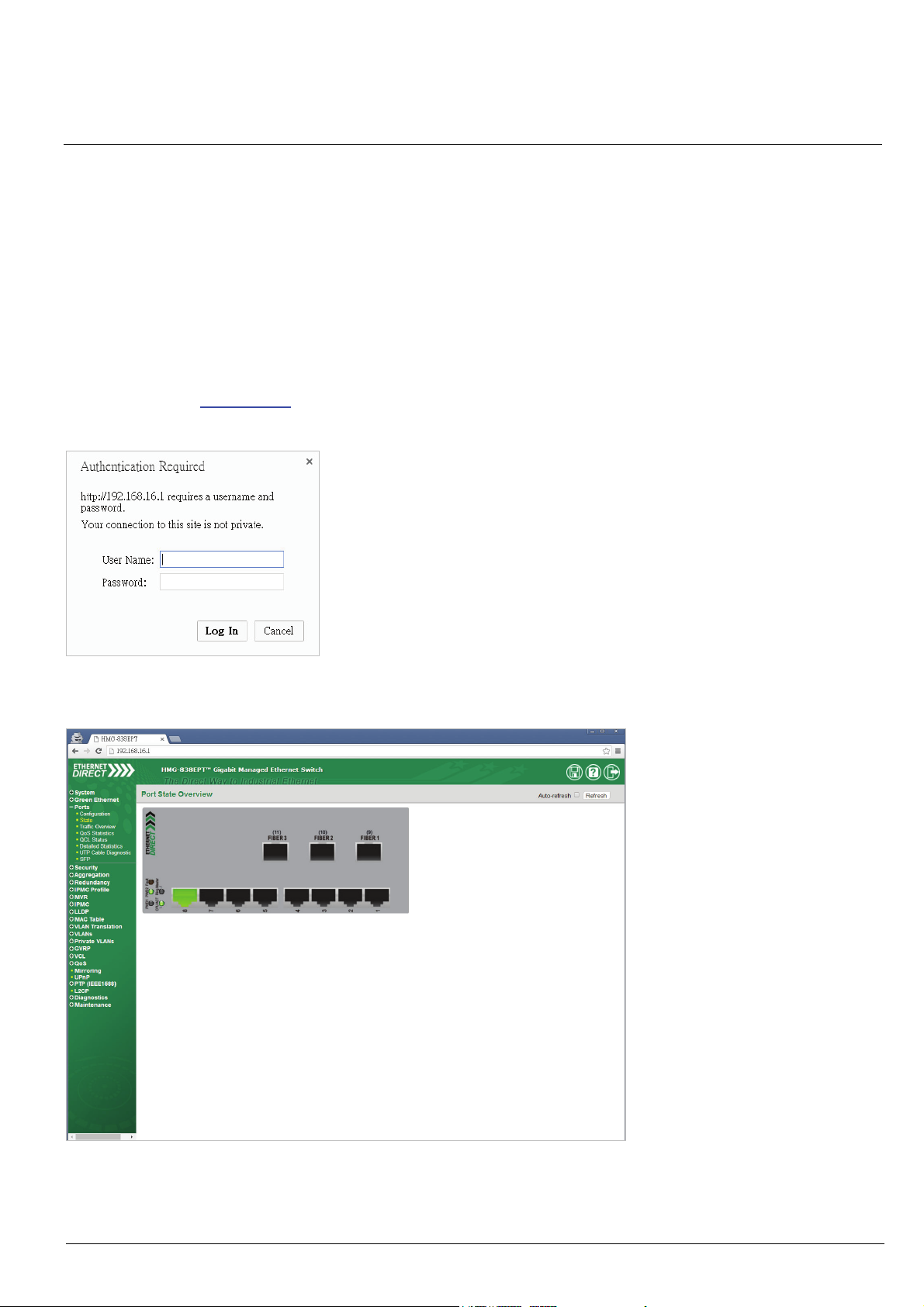
1-1 Entering Web Configuration
To enter the web based management for the first time or after returning the device back to factory defaults, input the
default IP address “192.168.16.1
type of browser used. The example below is with Chrome browser.
” in your web browser. Then, a standard login prompt will appear depending on the
Enter the Ethernet Direct factory default username “admin” with “no password”. After successfully entering the web
based management, the Port State page will appear.
1-2 Port State
The initial page, when logged in, displays a graphical overview of the port status for the electrical and optical ports. The
HMG-838PT & HMG-838EPT Web Configuration 1-1
"Green" port indicates a LAN connection with a speed of 100M. The "Amber" colored port indicates a LAN connection
speed of 1000M.
The status display can be reached by using the left side menu, and return to Ports > State.
Web Configuration Home
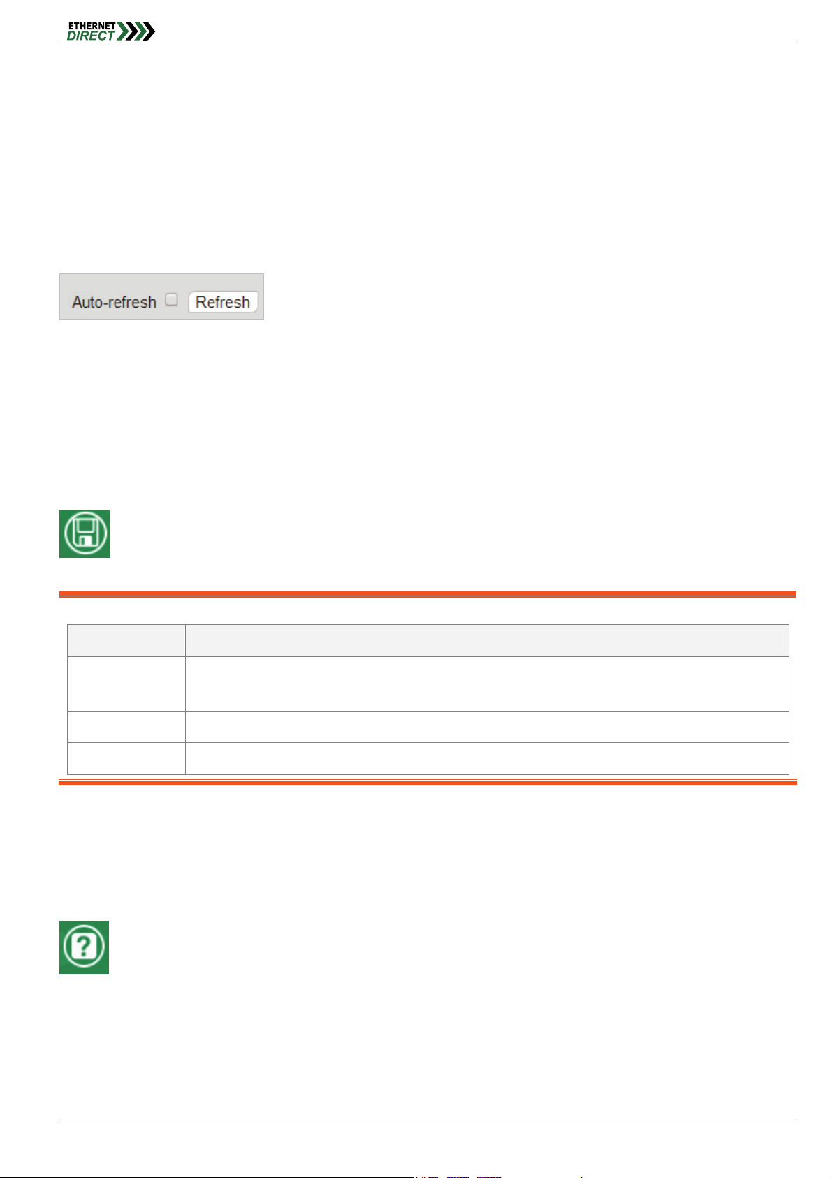
1-3 Refresh
To update the screen, click the "Refresh" button. For automatic updating of the screen, the "Auto-refresh" tick box may
be ticked. The screen will be auto refreshed every 3 seconds.
Unless connected directly on a local LAN, we recommend not using the auto-refresh function as it does generate a bit
of traffic.
1-4 Save
When there is configuration change in the switch, please do remember to click “Save” bottom to save the Running
Configuration (running-config) to Startup Configuration (startup-config), so those changes you make in the switch will be
save into the switch memory even there is power on/off.
Note: The difference between system configuration files:
File Name Definitions
running-config The current configuration, if do not use “Save” button to save this current configuration to system, it will be
lost after power on/off.
startup-config The current system startup configuration, it will not be affect by power on/off.
default-config The factory default configuration.
1-5 Help
The managed switch series has an online "help" system to aid the engineer when setting the parameters of the device.
Each functional setting page is accompanied by a specific "help" for that functional page. The user can display this help
"pop up" at any time by clicking the "help" icon.
1-6 Logout
After completing configuration, we recommend logging out of the web GUI. This is easily accomplished by clicking the
logout icon.
HMG-838PT & HMG-838EPT Web Configuration 1-2

Web Configuration Home
After clicking the logout icon, a confirmation screen will be displayed. Click "OK" to finish logging out or click "Cancel" to
return to the web configuration GUI.
For the remainder of this section, each menu item will be explained one by one, in order as they descend down the
menu screen, starting with the "System
" menu.
HMG-838PT & HMG-838EPT Web Configuration 1-3
Chapter 2
System
The configuration under the "System" menu includes device settings such as IP address, time server, etc.
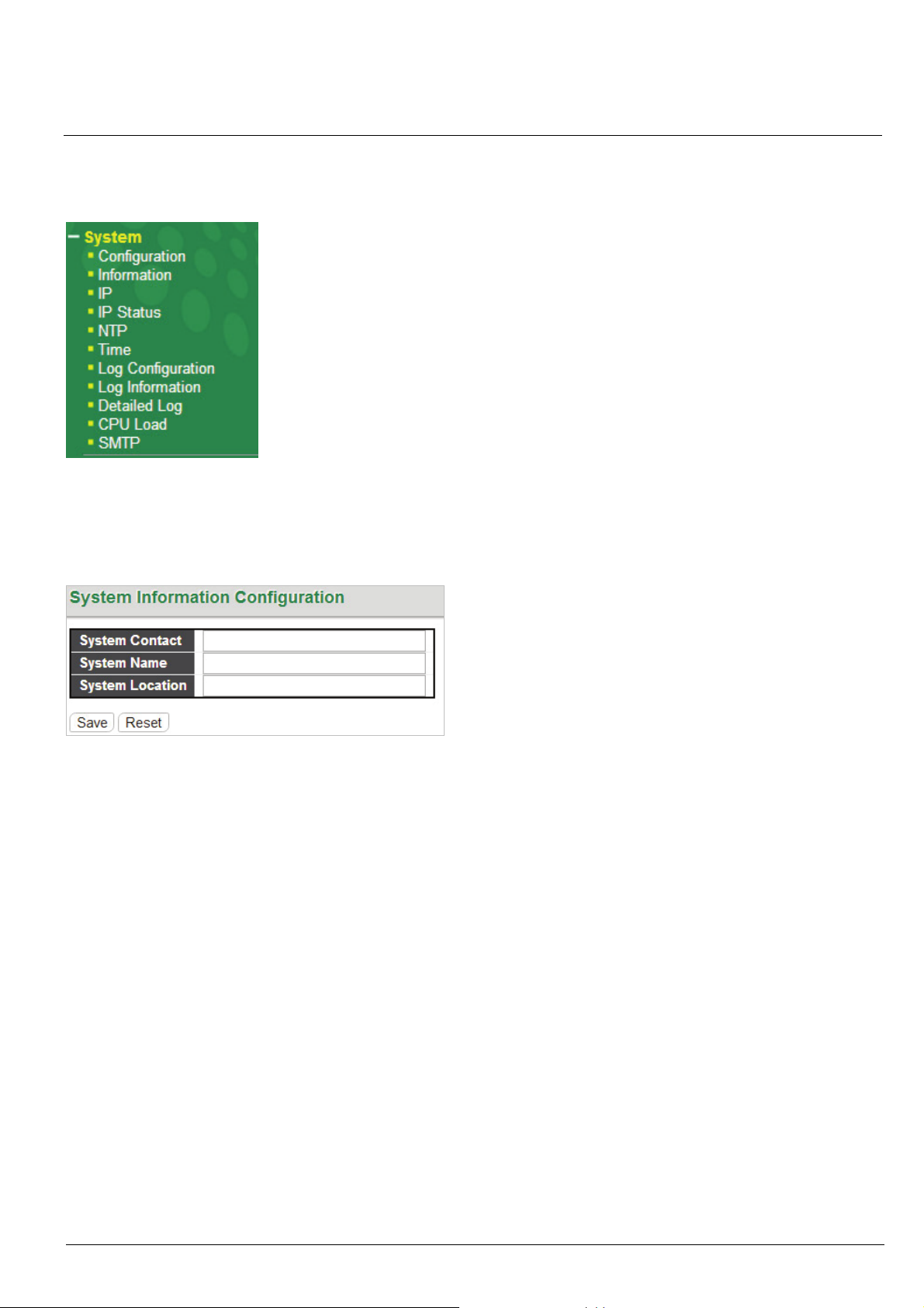
2-1 System Information Configuration
The configuration information entered here will be reported in the standard SNMP MIB2 for 'sysContact' (OID
1.3.6.1.2.1.1.4), 'sysName' (OID 1.3.6.1.2.1.1.5) and 'sysLocation' (OID 1.3.6.1.2.1.1.6). Remember to click the “Save”
button after entering the configuration information.
System Contact: Indicate the descriptive contact information. This could be a person’s name, email address or
other descriptions. The allowed string length is 0~255 and the allowed content is the ASCII characters from
32~126.
System Name: Indicate the hostname for this device. Alphabets (A-Z; a-z), digits (0-9) and minus sign (-) can be
used. However, space characters are not allowed. The first character must be an alphabet character. The first and
last character must not be a minus sign. The allowed string length is 0~255.
System Location: Indicate the location of this device. The allowed string length is 0~255.
2-2 System Information
The system information screen will display the configuration information of the system, in System section shows
“Contact”, “Name” and “Location”, the Hardware section shows “MAC Address” and “Hardware Version”, the Time
section shows “System Date” and “System Uptime" and the Software section shows the “Software Version” and
“Software Date”.
HMG-838PT & HMG-838EPT Web Configuration 2-1
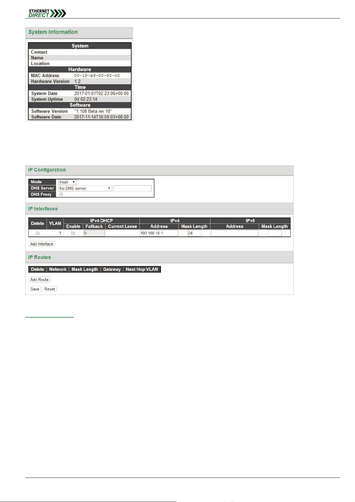
2-3 System IP
The section allows you to setup the switch’s IP configuration, interface and routes.
System
IP Configuration:
Mode: The pull-down configures whether the IP stack should act as a Host or a Router.
Host: IP traffic between interfaces will not be routed.
Router: Traffic is routed between all interfaces. When configuring this device for multiple VLANs, the Router
mode should be chosen.
DNS Server: This setting controls the DNS name resolution done by the switch. The following modes are
supported:
From any DHCP interfaces: The first DNS server offered from a DHCP lease to a DHCP-enabled interface
will be used.
No DNS server: No DNS server will be used.
Configured: Explicitly provide the IP address of the DNS Server in dotted decimal notation.
From this DHCP interface: Specify from which DHCP-enabled interface a provided DNS server should be
preferred.
DNS Proxy: When DNS proxy is enabled, the system will relay DNS requests to the currently configured DNS
server, and reply as a DNS resolver to the client devices on the network.
HMG-838PT & HMG-838EPT Web Configuration 2-2

System
IP Interface:
Click "Add Interface" to add a new IP interface. A maximum of 8 interfaces is supported.
VLAN: This is the VLAN associated with the IP interface. Only ports in this VLAN will be able to access the IP
interface. This field is only available for input when creating a new interface.
DHCP: When this checkbox is enabled, the system will configure the IPv4 address and mask of the interface
using the DHCP protocol. The DHCP client will announce the configured System Name as hostname to provide
DNS lookup.
IPv4 Address: The IPv4 address of the interface is entered in dotted decimal notation. If DHCP is enabled, this
field is not used. The field may also be left blank if IPv4 operation on the interface is not desired.
IPv4 Mask: The IPv4 network mask is entered by a number of bits (prefix length). Valid values are between 0 and
30 bits for a IPv4 address. If DHCP is enabled, this field is not used. The field may also be left blank if IPv4
operation on the interface is not desired.
IPv4 Current Lease: For DHCP interfaces with an active lease, this column shows the current interface address,
as provided by the DHCP server.
IPv6 Address: An IPv6 address is a 128-bit record represented as eight fields of up to four hexadecimal digits
with a colon separating each field (:). For example, fe80::215:c5ff:fe03:4dc7. The symbol :: is a special syntax that
can be used as a shorthand way of representing multiple 16-bit groups of contiguous zeros; but it can appear only
once. It can also represent a legally valid IPv4 address. For example, ::192.1.2.34. The field may be left blank if
IPv6 operation on the interface is not desired.
IPv6 Mask: The IPv6 network mask is entered by a number of bits (prefix length). Valid values are between 1 and
128 bits for an IPv6 address. The field may be left blank if IPv6 operation on the interface is not desired.
IP Routes:
Route Network: The IP route is the destination IP network or host address of this route. Valid format is dotted
decimal notation or a valid IPv6 notation. A default route can use the value 0.0.0.0 or for IPv6 use the :: notation.
Route Mask: The route mask is a destination IP network or host mask, in number of bits (prefix length). It defines
how much of a network address that must match, in order to qualify for this route. Valid values are between 0 and
32 bits respectively 128 for IPv6 routes. Only a default route will have a mask length of 0 (as it will match
anything).
Gateway: This is the IP address of the gateway. Valid format is dotted decimal notation or a valid IPv6 notation.
Gateway and Network must be of the same type.
2-4 System IP Status
Display the status of IP interfaces and routes.
HMG-838PT & HMG-838EPT Web Configuration 2-3

System
Please refer to “System IP” for the configuration of the interfaces and routes. This page is informational only.
2-5 System NTP
Display the status of IP interfaces and routes.
NTP Configuration:
Mode: Configure the NTP mode operation. Possible modes are:
Enabled: Enable NTP client mode operation.
Disabled: Disable NTP client mode operation.
Server #: Enter the IPv4 or IPv6 address of an NTP server. IPv6 address is in 128-bit records represented as
eight fields of up to four hexadecimal digits with a colon separating each field (:). For example,
'fe80::218:a9ff:fe00:4ec0'. The symbol '::' is a special syntax that can be used as a shorthand way of representing
multiple 16-bit groups of contiguous zeros; but it can appear only once. NTP servers can also be represented by a
legally valid IPv4 address. For example, '::192.1.2.34'. The NTP servers are tried in numeric order. If 'Server 1' is
unavailable, the NTP client will try to contact 'Server 2'.
Note: The NTP Server support is only support NTPv4 Protocol.
HMG-838PT & HMG-838EPT Web Configuration 2-4
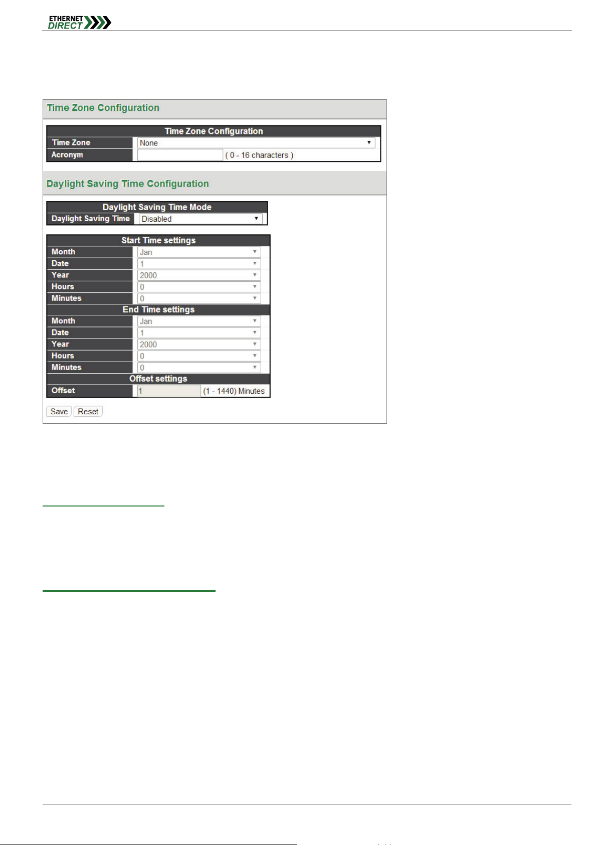
2-6 System Time
Setup the switch’s time from which time zone and daylight saving time mode.
System
The setting example above is for Eastern Standard Time in the United States. Daylight savings time starts on the
second Sunday in March at 2:00AM. Daylight savings ends on the first Sunday in November at 2:00AM. The daylight
savings time offset is 60 minutes (1 hour).
Time Zone Configuration:
Time Zone: Lists various Time Zones worldwide. Select appropriate Time Zone from the drop down and click
Save to set.
Acronym: Set the acronym of the time zone.
Daylight Saving Time Configuration:
Daylight Saving Time: This is used to set the clock forward or backward according to the configurations set
below for a defined Daylight Saving Time duration. Select “Disable” to disable the Daylight Saving Time
configuration. Select “Recurring” and configure the Daylight Saving Time duration to repeat the configuration
every year. Select “Non-Recurring” and configure the Daylight Saving Time duration for single time configuration.
(Default is Disabled)
Recurring & Non-Recurring Configurations:
Start time settings: Select the starting week, day, month, year, hours, and minutes.
End time settings: Select he ending week, day, month, year, hours, and minutes.
Offset settings: Enter the number of minutes to add during Daylight Saving Time. The allowed range is 1 to
1440.
2-7 System Log
HMG-838PT & HMG-838EPT Web Configuration 2-5
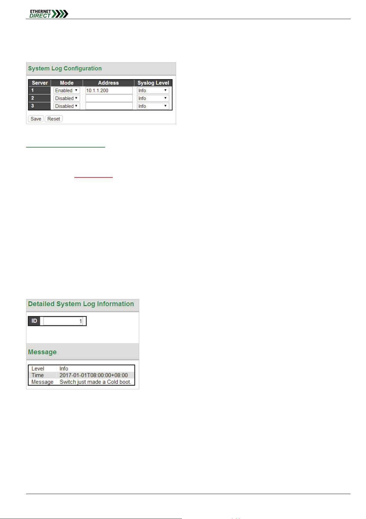
Setup a single or the multiple Remote System Log Servers on this page. The max. remote system log server can setup
to 3 servers.
System
System Log Configuration:
Server Mode: This sets the server mode operation. When the mode of operation is enabled, the syslog message
will send out to syslog server (at the server address). The syslog protocol is based on UDP communication and
received on UDP port 514
connectionless protocol and it does not provide acknowledgments. The syslog packet will always send out, even if
the syslog server does not exist. When the mode of operation is disabled, no syslog packets are sent out.
Server Address: This sets the IPv4 host address of syslog server. If the switch provides DNS feature, it also can
be a host name.
Syslog Level: This sets what kind of messages will send to syslog server. Possible levels are:
Info: Send information, warnings and errors.
Warning: Send warnings and errors.
Error: Send errors only.
. Syslog server will not send acknowledgments back to the sender since UDP is a
2-8 Detailed Log
This page shows displays of the individual system log records. And View each log, by ID number.
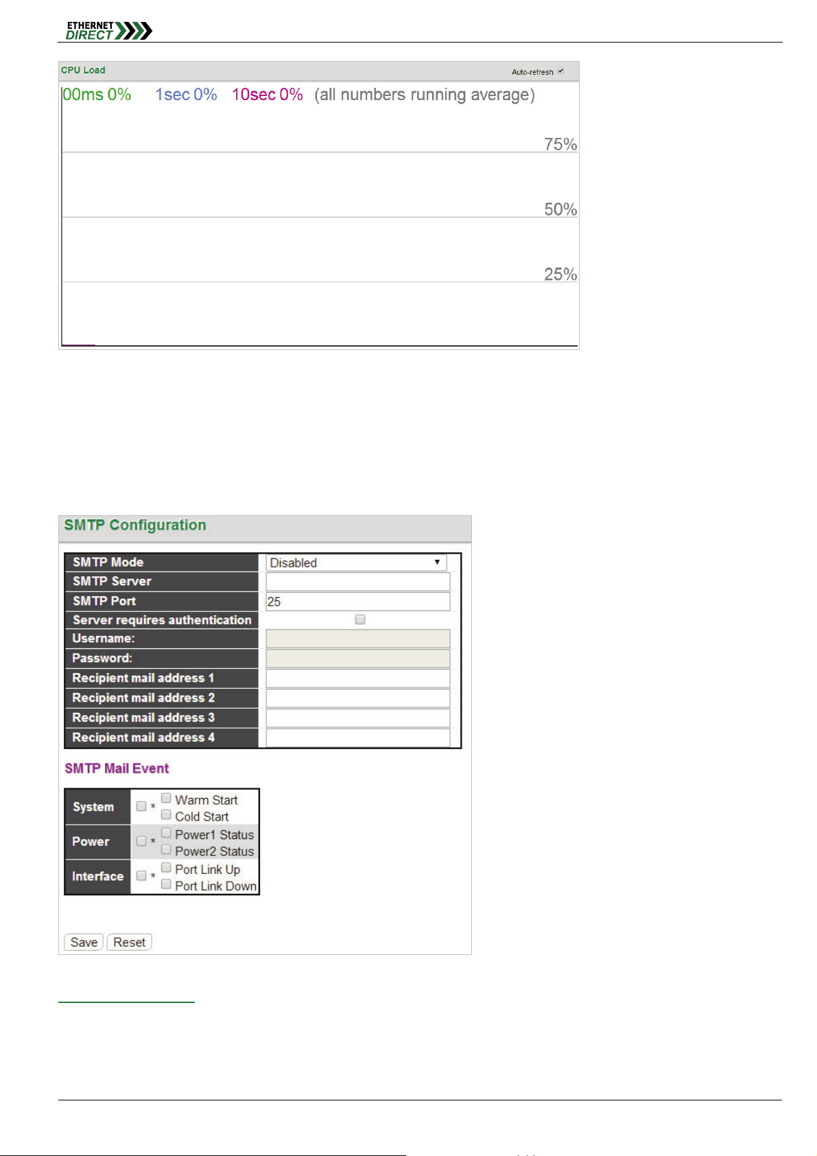
2-9 System CPU Load
This page displays the CPU load, using an SVG graph.
HMG-838PT & HMG-838EPT Web Configuration 2-6
System
The load is measured as averaged over the last 100ms, 1sec and 10 seconds intervals. The last 120 samples are
graphed, and the last numbers are displayed as text as well. In order to display the SVG graph, your browser must
support the SVG format. Automatic refresh occurs every 3 seconds.
2-10 System SMTP
Configure the email alert system.
SMTP Configuration:
SMTP Mode: Set the SMTP mode operation. Possible modes are:
Enabled: Enable SMTP client mode operation.
Disabled: Disable SMTP client mode operation.
SMTP Server: Set the SMTP server IP address (this is the server that will forward email).
HMG-838PT & HMG-838EPT Web Configuration 2-7

SMTP Port: Set the SMTP port number. The default SMTP port is 25.
Server requires authentication: Check this box if your server requires authentication. In most cases, this is
required and the following must be entered.
Username: Enter the valid authentication username for SMTP server
Password: Enter the authentication password for username of SMTP server
Recipient mail address: Up to four recipient's E-mail addresses may be entered to be sent alert emails.
SMTP Mail Event:
These check boxes select what events will result in alert email messages being generated and sent.
System: Enable/disable the System group's mail events. Possible mail events are:
Warm Start: Enable/disable Warm Start mail event.
Cold Start: Enable/disable Cold Start mail event.
Power: Enable/disable the Power group's mail events. Possible mail events are:
Power 1 Status: Enable/disable Power 1 status mail event.
Power 2 Status: Enable/disable Power 2 status mail event.
Interface: Enable/disable the Interface group's mail events. Possible mail events are:
Port Link Up: Enable/disable Port Link up mail event.
Port Link Down: Enable/disable Port Link down mail event.
System
HMG-838PT & HMG-838EPT Web Configuration 2-8
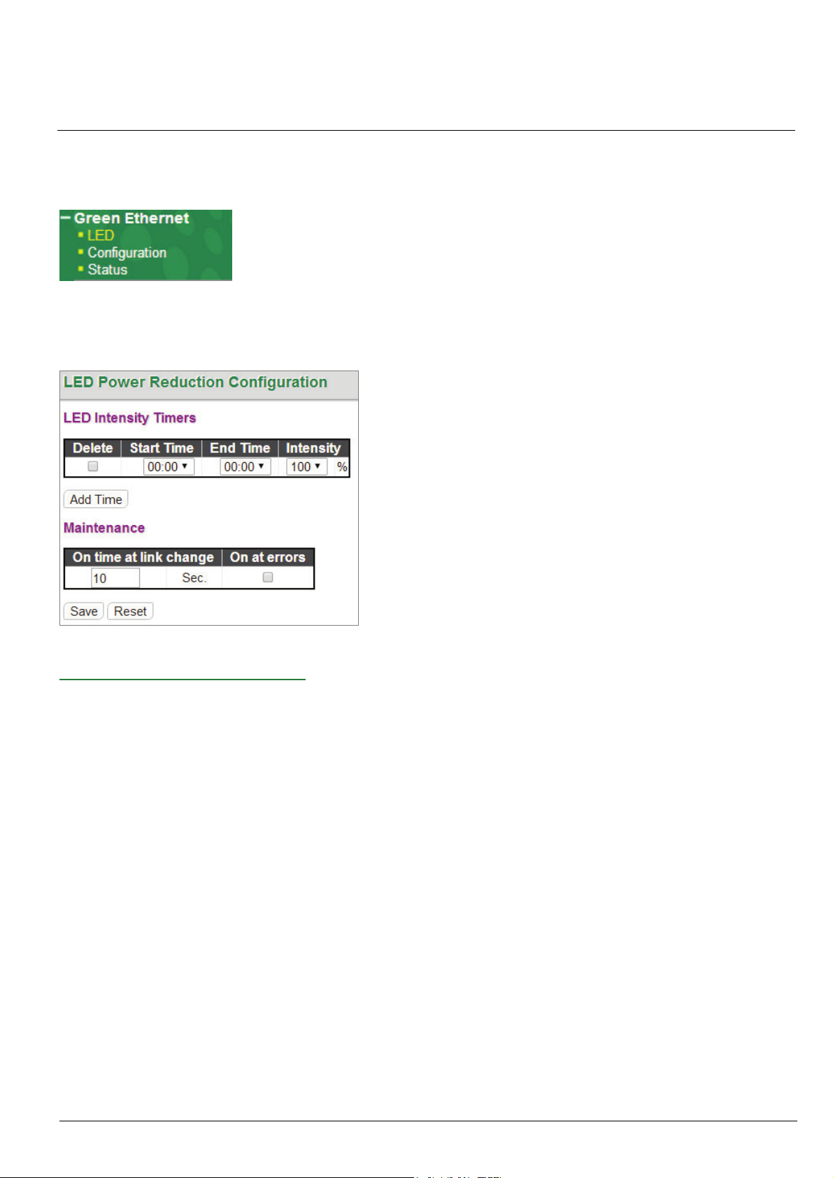
Chapter 3
Green Ethernet
The configuration under the "Green Ethernet" menu includes a number of power saving techniques.
3-1 Green Ethernet LED
Configure the LED light intensity to reduce power consumption.
LED Power Reduction Configuration:
The LED light intensity may be adjusted in a percentage of intensity during programmable time periods. In the above
setting example, the LED intensity has been adjusted to 50% during daylight hours and reduced to only 10% intensity
during night hours.
The maintenance checkbox will bring LED intensity to 100% for 10 seconds in the event of any error (such as link
down).
3-2 Green Ethernet Configuration
Configure EEE (Energy-Efficient Ethernet) as well as Ethernet power savings.
HMG-838PT & HMG-838EPT Web Configuration 3-1
Green Ethernet
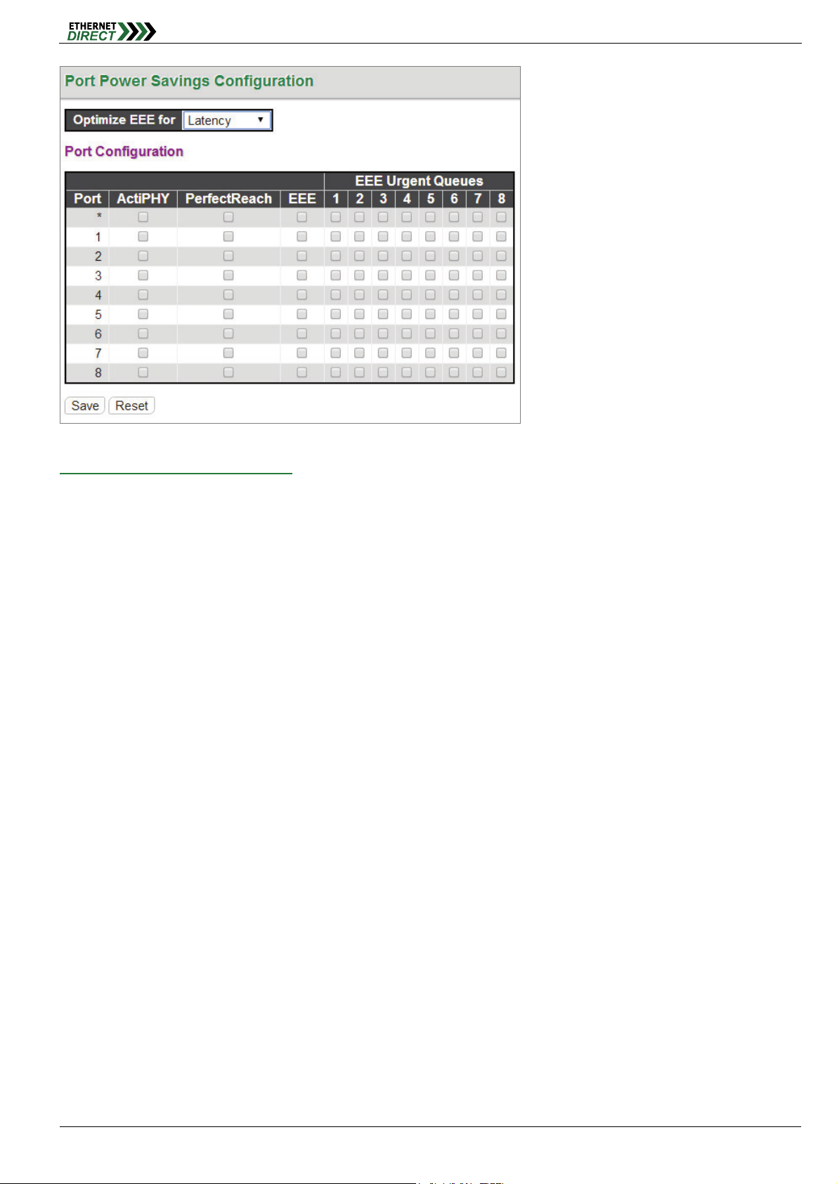
Port Power Savings Configuration:
Optimize EEE for: Enables/disables the EEE function for this switch. The two options are:
Power: The EEE function is enabled. This is the default setting.
Legacy: EEE is not enabled.
Port Configuration:
ActiPHY™: ActiPHY™ works by lowering the power for a port when there is no link. The port is power up for short
moment in order to determine if an Ethernet cable is inserted. For ports with no cable connection, the PHY
remains powered down to save energy.
PerfectReach™: PerfectReach™ is another power saving mechanism. PerfectReach™ works by determining the
cable length and lowering the Ethernet transmit power for ports with short cables.
EEE (Energy-Efficient Ethernet): EEE is a power saving option that reduces the power usage when there is low
or no traffic utilization. EEE was developed through the IEEE802.3az task force of the Institute of Electrical and
Electronic Engineers (IEEE). EEE works by powering down circuits when there is no traffic. When a port gets data
to be transmitted all circuits are powered up. The time it takes to power up the circuits is called wakeup time. The
default wakeup time is 30 us for 100Mbit links. EEE devices must agree upon the value of the wakeup time in
order to make sure that both the receiving and transmitting device has all circuits powered up when traffic is
transmitted. The devices can exchange wakeup time information using the LLDP (Link Layer Discovery Protocol)
protocol. EEE works for ports in auto-negotiation mode, where the port is negotiated to either 10 or 100 Mbit full
duplex modes. For ports that are not EEE-capable the corresponding EEE checkboxes are grayed out and thus
impossible to enable EEE for.
When a port is powered down for saving power, outgoing traffic is stored in a buffer until the port is powered up
again. Because there are some overhead in turning the port down and up, more power can be saved if the traffic
can be buffered up until a large burst of traffic can be transmitted. Buffering traffic will give some latency in the
traffic. For traffic that should not be held back, urgent queues may be assigned to reduce latency yet still result in
overall power saving.
EEE Urgent Queues: It is possible to minimize the latency for specific frames, by mapping the frames to a
specific queue (done with QOS), and then mark the queue as an urgent queue. When an urgent queue gets data
to be transmitted, the circuits will be powered up at once and the latency will be reduced to the wakeup time.
Queues set will activate transmission of frames as soon as data is available. Otherwise the queue will postpone
HMG-838PT & HMG-838EPT Web Configuration 3-2
transmission until a burst of frames can be transmitted.
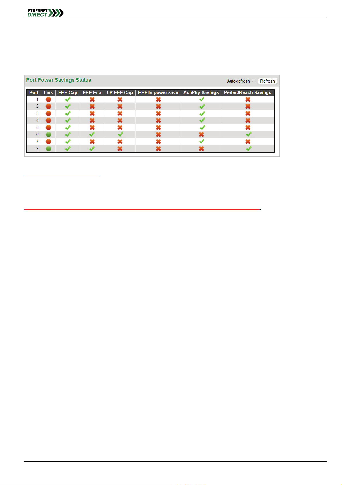
3-3 Green Ethernet Status
Display the energy saving status for all ports.
Green Ethernet
Port Power Savings Status:
In the above we can see that port 8 is saving power through PerfectReach™ as the Ethernet cable is short. Our port 6 is
connected to an EEE compliant device but with short cable, so we have savings both by EEE and PerfectReach™. As
for rest other ports do not linked to any devices, so they are saving power via ActiPHY™. It should be noted that
Ethernet power savings do not apply to the optical fiber ports, only to the electrical LAN ports.
HMG-838PT & HMG-838EPT Web Configuration 3-3
Chapter 4
Configurations related to the fiber and electrical ports are performed under the Ports menu.
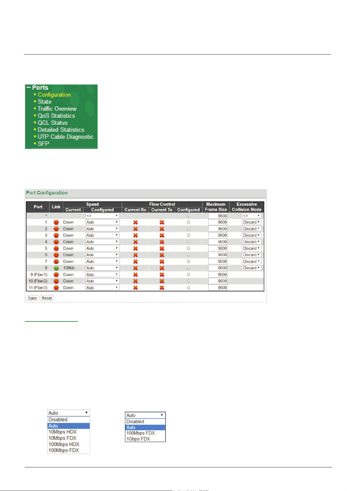
4-1 Ports Configuration
This page displays current port configurations and allows some configuration here.
Ports
Port Configuration:
Port: This device is an industrial switch with 8 electrical LAN ports numbered 1~8 and 3 fiber optical ports (for
SFP modules) numbered 9~11. Each logical port number is displayed in a row. The select all "*" port will apply
actions on all ports.
Link: The current link state for each port is displayed graphically. Green indicates the link is up and red that it is
down.
Current Speed: This column provides the current link speed (10, 100, 1G) and duplex (fdx=Full Duplex, hdx=Half
Duplex) of each port.
Configured Speed: This pull down selects any available link speed for the given switch port. Only speeds
supported by the specific port are shown.
Copper Ports
Fiber Ports
HMG-838PT & HMG-838EPT Web Configuration 4-1
Possible copper port settings are:
Disabled: Disables the switch port operation.
Auto: Port auto negotiating speed with the link partner, selecting the highest speed that is compatible with
the link partner and negotiating the duplex mode.
10Mbps HDX: Forces the port to 10Mbps half duplex mode.
10Mbps FDX: Forces the port to 10Mbps full duplex mode.
100Mbps HDX: Forces the port to 100Mbps half duplex mode.
100Mbps FDX: Forces the port to 100Mbps full duplex mode.
Possible fiber port settings are:
Disabled: Disables the switch port operation.
Auto: The auto-negotiation function in fiber optic network is to negotiate on the duplex mode only, not the
speed of the SFP.
100Mbps FDX: Forces the fiber port to 100Mbps full duplex mode.
1Gbps FDX: Forces the fiber port to 1Gbps full duplex mode. (System Default)
Flow Control: The Current Rx column indicates whether pause frames on the port are obeyed, and the Current
Tx column indicates whether pause frames on the port are transmitted. The Rx and Tx settings are determined by
the result of the last Auto-Negotiation. Check the configured column to use flow control. This setting is also related
to the setting for Configured Link Speed.
Ports
Maximum Frame Size: Enter the maximum frame size allowed for the switch port, including FCS. This switch
supports up to 9600 byte packets.
Excessive Collision Mode: This setting configures the port transmit collision behavior to either "Discard"
(Discard frame after 16 collisions - default) or to "Restart" (Restart back off algorithm after 16 collisions).
Note: The Auto-Negotiation function that supported by SFP port, is to negotiate on the duplex mode only, not the speed of the SFP,
our system’s default speed for SFP port is 1Gbps, if you wish to use 100Mbps SFP module please manually setup the port speed
to “100Mbps FDX”.
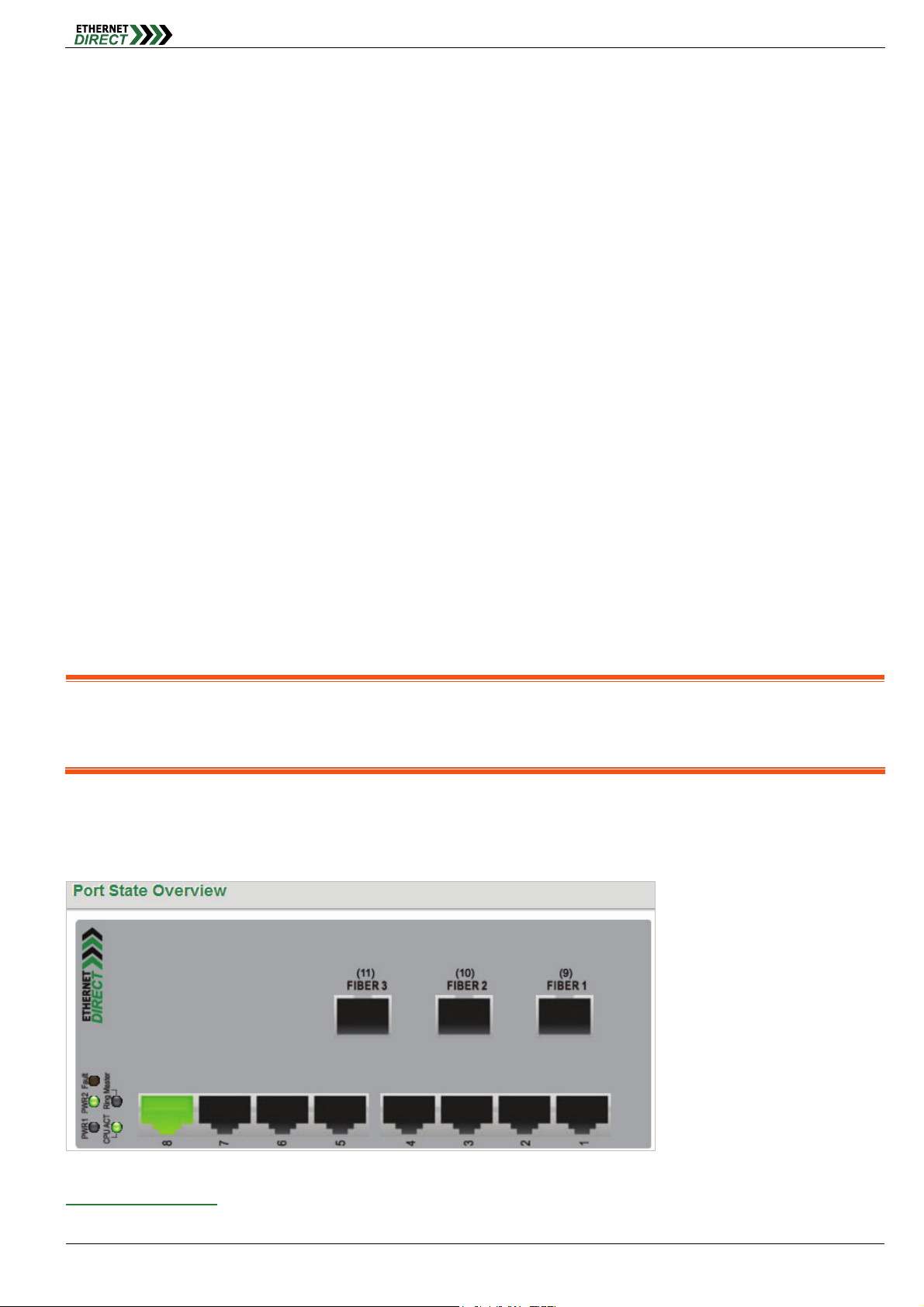
4-2 Ports State
Display an overview graphic of the switch.
Port State Overview:
This is the same graphic overview shown when first logging into the switch for management. "Green" colored ports
HMG-838PT & HMG-838EPT Web Configuration 4-2
indicate a 100M linked state, while "Amber" colored ports indicate a 1G linked state. "Dark Grey" ports have no link. The
link status display can be updated by clicking the "Refresh" button. When "Auto-refresh" is checked, the display will be
updated every 3 seconds.
Ports
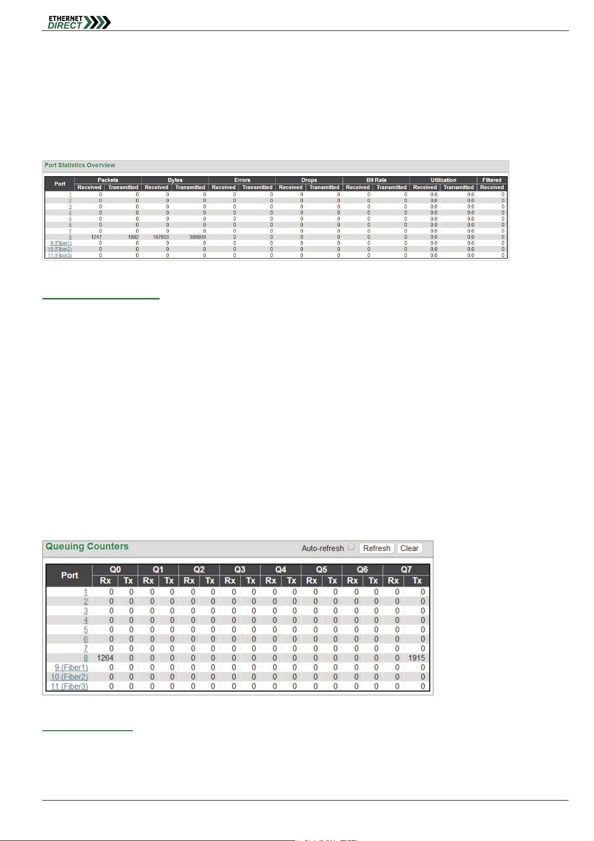
4-3 Ports Traffic Overview
This page displays a comprehensive port traffic overview of the switch.
Port Statistics Overview:
The displayed counters are:
Port: The logical port (1~11) for the data contained in the same row.
Packets: The number of received and transmitted packets per port.
Bytes: The number of received and transmitted bytes per port.
Errors: The number of frames received in error and the number of incomplete transmissions per port.
Drops: The number of frames discarded due to ingress or egress congestion.
Filtered: The number of received frames filtered by the forwarding process.
The counter display can be updated by clicking the "Refresh" button. When "Auto-refresh" is checked, the display will
be updated every 3 seconds. Clicking the "Clear" button will zero all counters and start counting again.
4-4 Ports QoS Statistics
This page provides statistics for the different queues for all switch ports.
Queuing Counters:
The displayed counters are:
Port: The logical port for the settings contained in the same row.
Qn: There are 8 QoS queues per port. Q0 is the lowest priority queue.
HMG-838PT & HMG-838EPT Web Configuration 4-3

Rx/Tx: The number of received and transmitted packets per queue.
4-5 Ports QCL Status
This page shows the QCL status by different QCL users.
Ports
QoS Control List Status:
Each row describes the QCE that is defined. It is a conflict if a specific QCE is not applied to the hardware due to
hardware limitations. The maximum number of QCEs is 256 on each switch.
User: Indicates the QCL user.
QCE#: Indicates the index of QCE.
Frame Type: Indicates the type of frame to look for incoming frames. Possible frame types are:
Any: The QCE will match all frame type.
Ethernet: Only Ethernet frames (with Ether Type 0x600-0xFFFF) are allowed.
LLC: Only (LLC) frames are allowed.
SNAP: Only (SNAP) frames are allowed.
IPv4: The QCE will match only IPV4 frames.
IPv6: The QCE will match only IPV6 frames.
Port: Indicates the list of ports configured with the QCE.
Action: Indicates the classification action taken on ingress frame if parameters configured are matched with the
frame's content. There are three action fields: Class, DPL and DSCP.
Class: Classified QoS class; if a frame matches the QCE it will be put in the queue.
DPL: Drop Precedence Level; if a frame matches the QCE then DP level will set to value displayed under
DPL column.
DSCP: If a frame matches the QCE then DSCP will be classified with the value displayed under DSCP
column.
Conflict: Displays Conflict status of QCL entries. As H/W resources are shared by multiple applications, it may
happen that resources required to add a QCE may not be available. In that case it shows conflict status as 'Yes',
otherwise it is always 'No'. Please note that conflict can be resolved by releasing the H/W resources required to
add QCL entry on pressing 'Resolve Conflict' button.
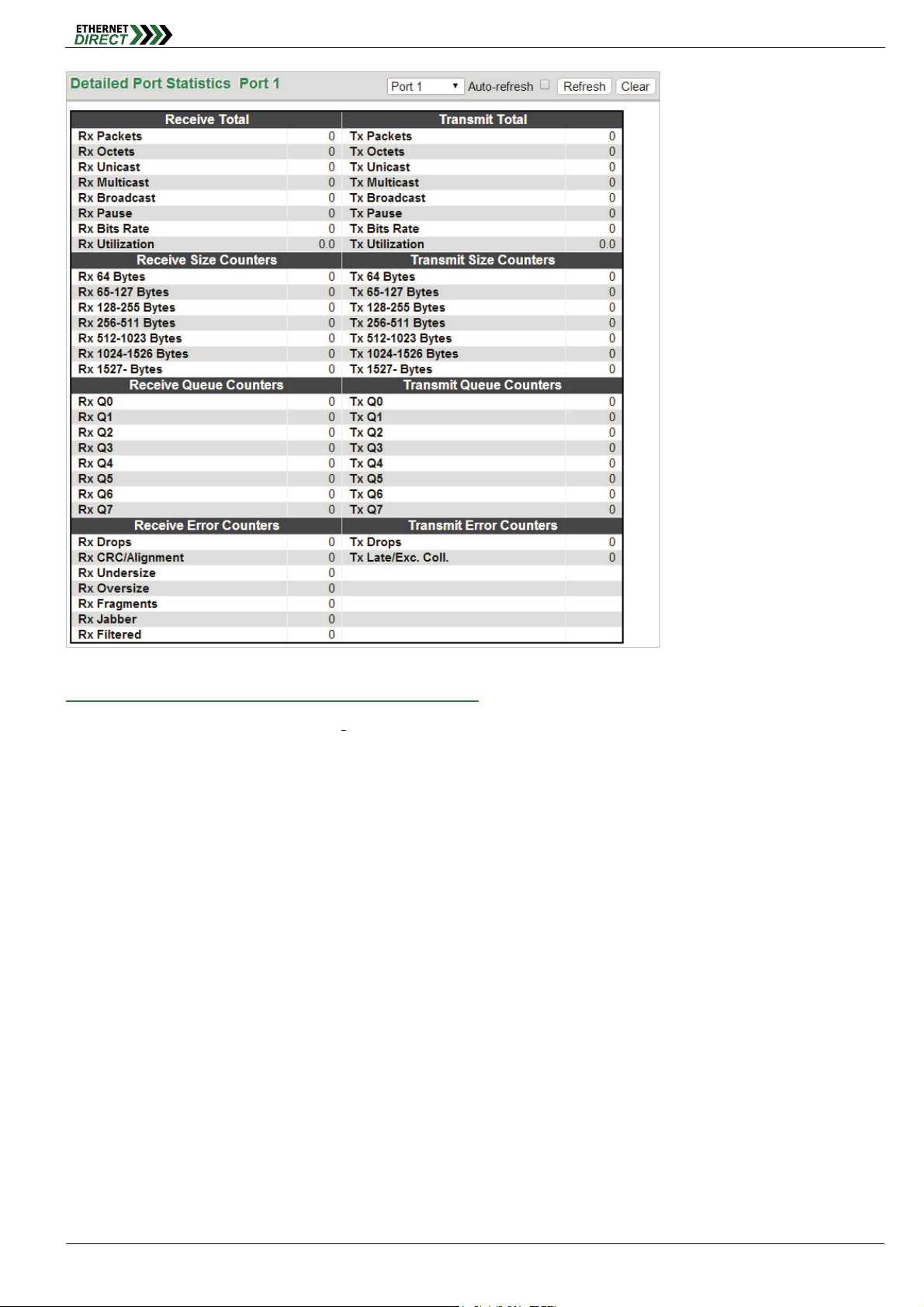
4-6 Ports Detailed Statistics
This page provides detailed traffic statistics for a specific switch port. The displayed counters are the totals for receive
and transmit, the size counters for receive and transmit, and the error counters for receive and transmit. Use the port
select pull down to select which switch port details to display.
HMG-838PT & HMG-838EPT Web Configuration 4-4
Ports
Detailed Port Statistics (Port 1: Port number selectable):
Receive Total and Transmit Total:
Rx and Tx Packets: The number of received and transmitted (good and bad) packets.
Rx and Tx Octets: The number of received and transmitted (good and bad) bytes. Includes FCS, but
excludes framing bits.
Rx and Tx Unicast: The number of received and transmitted (good and bad) unicast packets.
Rx and Tx Multicast: The number of received and transmitted (good and bad) multicast packets.
Rx and Tx Broadcast: The number of received and transmitted (good and bad) broadcast packets.
Rx and Tx Pause: A count of the MAC Control frames received or transmitted on this port that have an
opcode indicating a PAUSE.
Receive and Transmit Size Counters: Displays the number of received and transmitted (good and bad) packets
split into categories based on their respective frame sizes.
Receive and Transmit Queue Counters: Displays the number of received and transmitted packets per input and
output queue.
Receive Error Counters:
Rx Drops: the numbers of frames dropped due to lack of receive buffers or egress congestion.
Rx CRC/Alignment: The number of frames received with CRC or alignment errors.
Rx Undersize: The number of short
Rx Oversize: The number of long
Rx Fragments: The number of short
HMG-838PT & HMG-838EPT Web Configuration 4-5
1
frames received with valid CRC.
2
frames received with valid CRC.
1
frames received with invalid CRC.
Rx Jabber: The number of long
2
frames received with invalid CRC.
Ports
Rx Filtered: The number of received frames filtered by the forwarding process.
1
Short frames are frames that are smaller than 64 bytes.
2
Long frames are frames that are longer than the configured maximum frame length for this port.
Transmit Error Counters:
Tx Drops: The number of frames dropped due to output buffer congestion.
Tx Late/Exc. Coll.: The number of frames dropped due to excessive or late collisions.
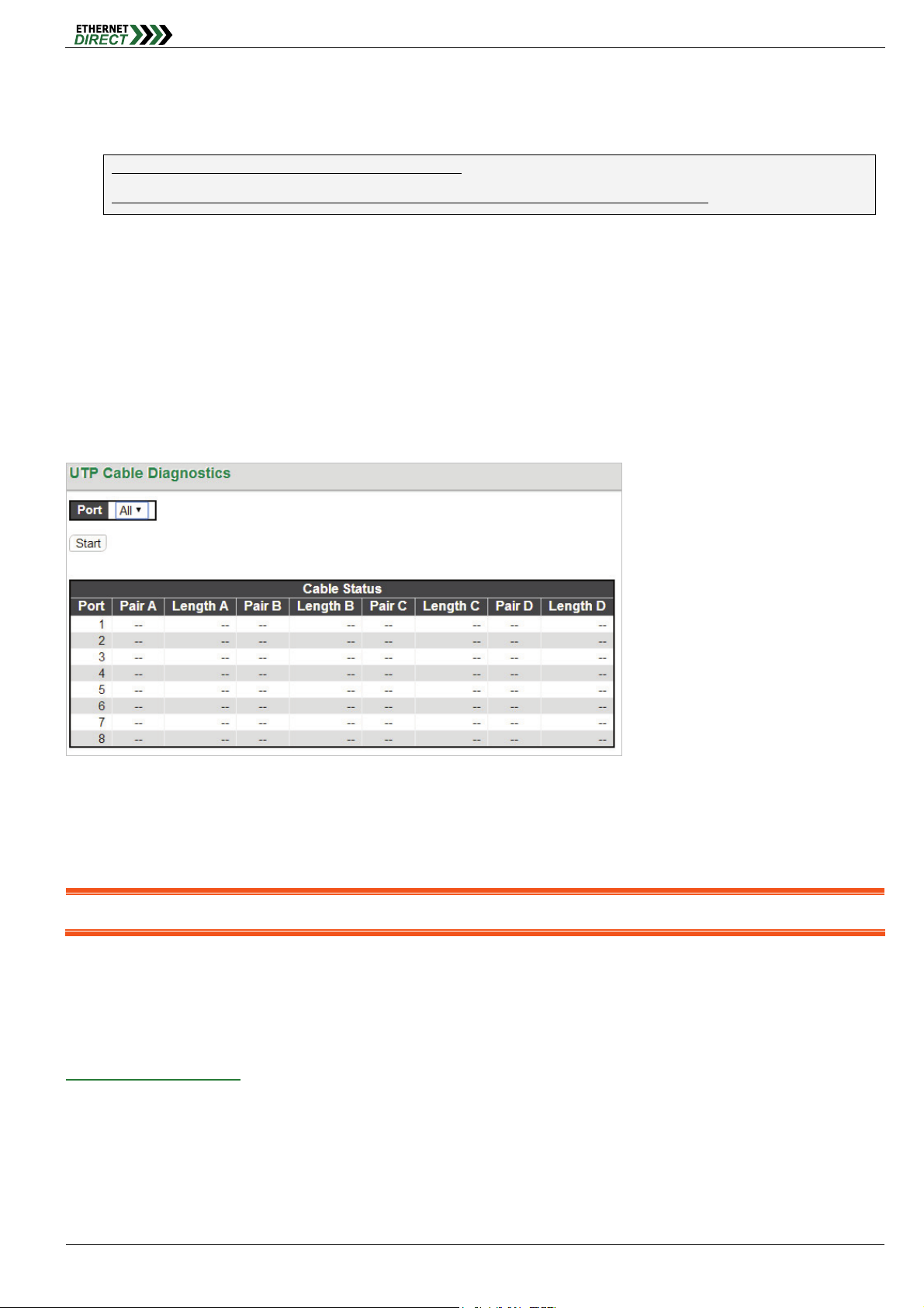
4-7 UTP Cable Diagnostics
This page is used for running the UTP Cable Diagnostics for 10/100 and 1G copper ports. Select which ports to run, or
all. Click "Start".
This will take approximately 5 seconds per port. If all ports are selected, this can take approximately 15 seconds.
When completed, the page refreshes automatically, and you can view the cable diagnostics results in the cable status
table.
Note: This function is only accurate for cables of length 7 - 140 meters.
10 and 100 Mbps ports will be linked down while running UTP Cable Diagnostics. Therefore, running UTP Cable
Diagnostics on a 10 or 100 Mbps management port will cause the switch to stop responding until UTP Cable
Diagnostics is complete.
UTP Cable Diagnostics:
Port: Port number.
Pair: The status of the cable pair.
OK: Correctly terminated pair
Open: Open pair
Short: Shorted pair
HMG-838PT & HMG-838EPT Web Configuration 4-6
Short A: Cross-pair short to pair A
Short B: Cross-pair short to pair B
Short C: Cross-pair short to pair C
Short D: Cross-pair short to pair D
Cross A: Abnormal cross-pair coupling with pair A
Cross B: Abnormal cross-pair coupling with pair B
Cross C: Abnormal cross-pair coupling with pair C
Cross D: Abnormal cross-pair coupling with pair D
Length: The length (in meters) of the cable pair. The resolution is ±3 meters.
Note: This function is only applicable to the Cooper (RJ-45) ports. It is not applicable to the optical ports.
Ports
This page is used for running the UTP Cable Diagnostics for 10/100 and 1G copper ports. Select which ports to run, or
all. Click "Start"
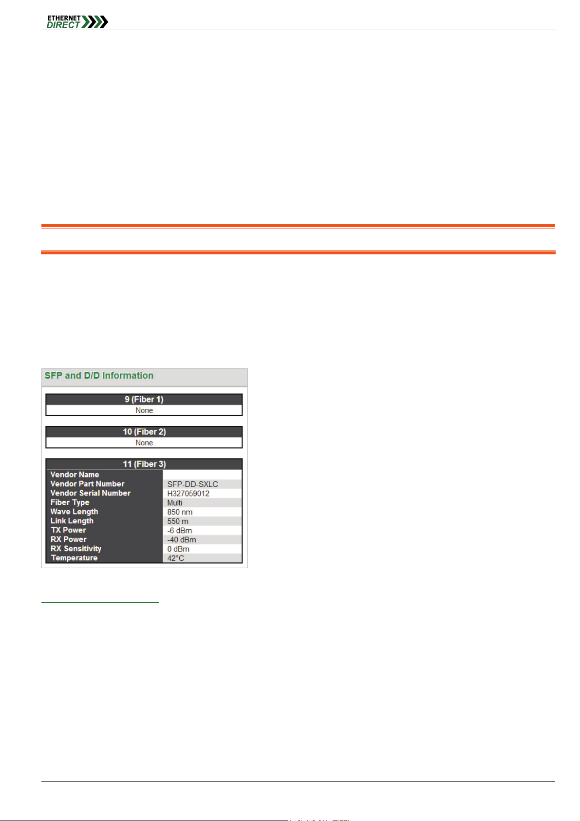
4-8 Ports SFP
This page displays current SFP status for all three fiber ports.
SFP and D/D Information:
Vendor Name: SFP vendor (manufacturer's) name.
Vendor Part: Manufacture's part number, provided by SFP vendor.
Fiber Type: Fiber type of either single or multi mode.
Wave Length: Laser wavelength Tx.
Wave Length 2: Laser wavelength Rx. (not all SFP support this reading)
Link Length: Link Length. (This is a marketing specification for this SFP module, not an actual measurement.)
TX Power: The laser diode transmits power is reported by the SFP that support DDI (Digital Diagnostic monitoring
Interface).
RX Power: The Receive Optical Power is reported by SFP that support DDI.
HMG-838PT & HMG-838EPT Web Configuration 4-7

RX Sensitivity: The Receive Sensitivity is reported by SFP that support DDI.
Temperature: The internal temperature is reported by SFP that support DDI.
Ports
HMG-838PT & HMG-838EPT Web Configuration 4-8
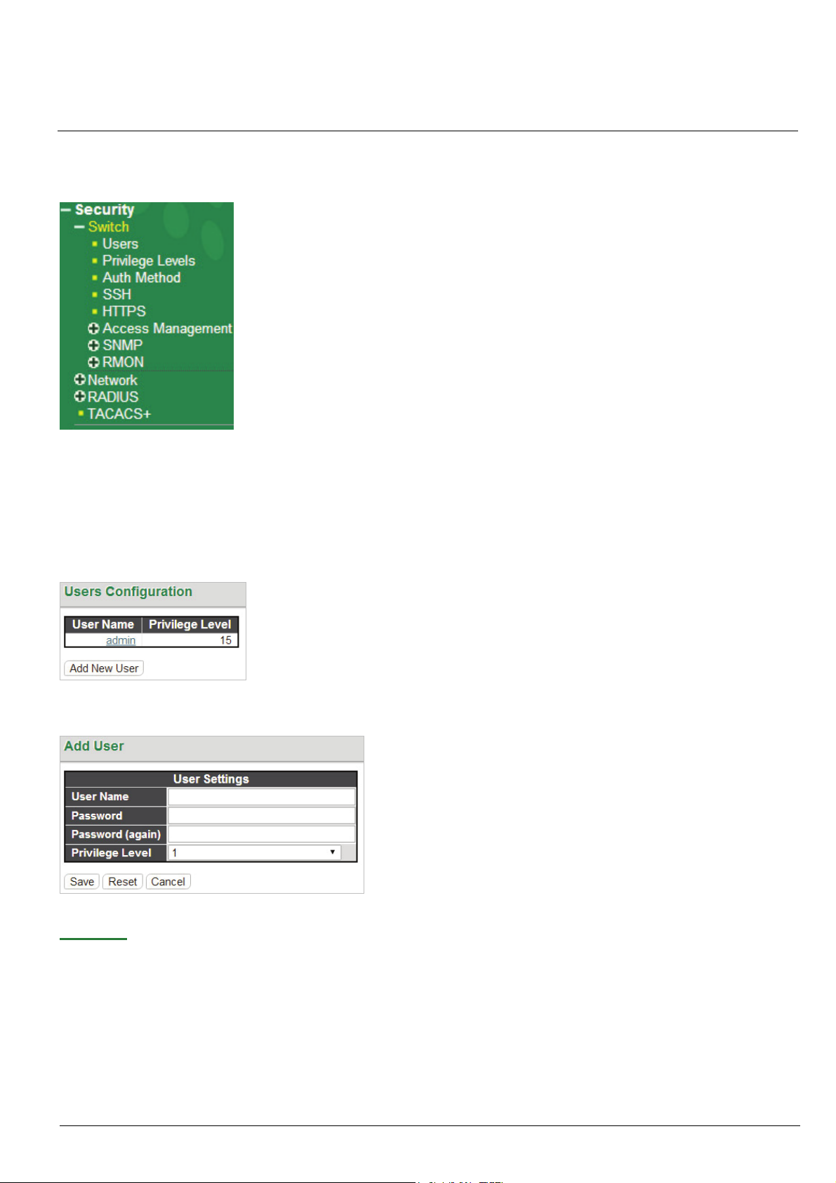
Under the Security heading are three major icons, Switch, Network and RADIUS.
Chapter 5
Security
5-1 Switch
5-1.1 User
This page provides an overview of the current users. Currently the only way to login as another user on the web server
is to close and reopen the browser.
By default, there is only one user, 'admin', assigned the highest privilege level of 15. Click the entries in User Name
column to edit the existing users. Or click the “Add New User” button to insert a new user entry.
Add User:
User Name: Enter the new user name.
Password: Enter the password for this user account.
Password (again): Retype the password for this user account.
Privilege Level: Select the appropriate privilege level for this user account. The allowed range is 1 to 15. If the
HMG-838PT & HMG-838EPT Web Configuration 5-1
privilege level value is 15, it can access all groups, i.e. that is granted the fully control of the device. But other
values need to refer to each group privilege level. User's privilege should be same or greater than the group
privilege level to have the access of that group. By default setting, most groups’ privilege level 5 has the read-only
access and privilege level 10 has the read-write access. And the system maintenance (software upload, factory

defaults and etc.) need user privilege level 15. Generally, the privilege level 15 can be used for an administrator
account, privilege level 10 for a standard user account and privilege level 5 for a guest account.
5-1.2 Privilege Levels
This page provides an overview of the privilege levels.
Security
Privilege Level Configuration:
Group Name: This name identifies the privilege group. In most cases, a privilege level group consists of a single
module (e.g. LACP, RSTP or QoS), but a few of them contains more than one. The following description defines
these privilege level groups in details:
System: Contact, Name, Location, Timezone, Daylight Saving Time, Log.
Security: Authentication, System Access Management, Port (contains Dot1x port, MAC based and the MAC
Address Limit), ACL, HTTPS, SSH, ARP Inspection, IP source guard.
IP: Everything except 'ping'.
Port: Everything except '
Diagnostics: 'ping' and '
Maintenance: CLI- System Reboot, System Restore Default, System Password, Configuration Save,
Configuration Load and Firmware Load. Web- Users, Privilege Levels and everything in Maintenance.
Privilege Levels: Every group has an authorization Privilege level for the following sub groups:
HMG-838PT & HMG-838EPT Web Configuration 5-2
UTP Cable Diagnostics'.
UTP Cable Diagnostics'.

configuration read-only
configuration/execute read-write
status/statistics read-only
status/statistics read-write (e.g. for clearing of statistics)
User Privilege should be the same or greater than the authorization Privilege level to have access to that group.
5-1.3 Auth Method
This page allows you to configure how users are authenticated when they log into the switch via one of the
management client interfaces.
Security
Authentication Method Configuration:
Client: The management client for which the configuration below applies.
Methods: Method can be set to one of the following values:
no: Authentication is disabled and login is not possible.
local: Use the local user database on the switch for authentication.
radius: Use remote RADIUS server(s) for authentication.
tacacs+: Use remote TACACS+ server(s) for authentication.
Note: Methods that involve remote servers will time out if the remote servers are offline. In this case the next method is tried. Each
method is tried from left to right and continues until a method either approves or rejects a user. If a remote server is used for
primary authentication it is recommended to configure secondary authentication as 'local'. This will enable the management client
to login via the local user database if none of the configured authentication servers are alive.
5-1.4 SSH
This page allows you to configure the SSH
SSH Configuration:
Mode: Indicates the SSH mode operation. Possible modes are:
Enabled: Enable SSH mode operation. By default, SSH mode operation is enabled.
Disabled: Disable SSH mode operation.
HMG-838PT & HMG-838EPT Web Configuration 5-3

Security
Note: SSH is preferred to Telnet, unless the management network is trusted. Telnet passes authentication credentials in
plain text, making those credentials susceptible to packet capture and analysis. SSH provides a secure authentication
method. The SSH in this device uses version 2 of SSH protocol.
5-1.5 HTTPS
This page allows you to configure the HTTPS
HTTPS Configuration:
Mode: Indicates the HTTPS operation mode. When the current connection is HTTPS and HTTPS mode operation
is disabled, web browser will automatically redirect to an HTTP connection. Possible modes are:
Enabled: Enable HTTPS mode operation.
Disabled: Disable HTTPS mode operation.
Automatic Redirect: Indicates the HTTPS redirect mode operation. It applies only if HTTPS mode "Enabled" is
selected. Automatically redirects HTTP of web browser to an HTTPS connection when both HTTPS mode and
Automatic Redirect are enabled. Possible modes are:
Enabled: Enable HTTPS redirect mode operation.
Disabled: Disable HTTPS redirect mode operation.
HTTPS Certificate Update: (Manage the SSL Certificate)
Certificate File: Click “Choose File” and select a SSL certificate file to be upload, the file extension maybe *.crt.
Private Key File: Click “Choose File” and select a private key file of your certificate to be upload, the file extension
maybe *.pem or *.key. (the size of private key file is up to 4K)
Pass Phrase: Enter a password for your certificate file.
Certificate Status: Shows the secure certificate status of the switch.
Click the “Upload” button to insert a new entry to the list.
Click “Generate Certificate” button and you can regenerate the default built-in certificate. (The switch comes with
built-in certificate for secure http (https) access)
HMG-838PT & HMG-838EPT Web Configuration 5-4

Note: Make sure you have enter all fields of “Certificate File, Private Key File, Pass Phrase” before you upload the SSL
certificate.
Security
5-1.6 Access Management
5-1.6.1 Access Management Configuration
Configure the access management table on this page. The maximum number of entries is 16. If the application's type
matches any one of the access management entries, it will be allowed access to the switch.
Access Management Configuration:
Mode: Indicates the access management mode operation. Possible modes are:
Enabled: Enable access management mode operation.
Disabled: Disable access management mode operation.
VLAN ID: Indicates the VLAN ID for the access management entry.
Start IP address: Indicates the start IP address for the access management entry.
End IP address: Indicates the end IP address for the access management entry.
HTTP/HTTPS: Checked indicates that the matched host can access the switch from HTTP/HTTPS interface.
SNMP: Checked indicates that the matched host can access the switch from SNMP.
TELNET/SSH: Indicates that the matched host can access the switch from TELNET/SSH interface.
Click the “Add New Entry” button to insert a new entry to the list.
Click the “Delete” button to remove a newly-inserted entry or select the checkbox to remove a saved entry during the
next save.
Click the “Save” button to save settings or changes.
Click the “Reset” button to restore changed settings to the default settings.
5-1.6.2 Access Management Statistics
This page provides statistics for access management.
Access Management Statistics:
HMG-838PT & HMG-838EPT Web Configuration 5-5

Interface: The interface type through which any remote host can access the switch.
Received Packets: The number of received packets from the interface when access management mode is
enabled.
Allowed Packets: The number of allowed packets from the interface when access management mode is
enabled.
Discarded Packets: The number of discarded packets from the interface when access management mode is
enabled.
Security
5-1.7 SNMP
5-1.7.1 SNMP System Configuration
This page let you configure the SNMP.
SNMP System Configuration:
Mode: Indicates the SNMP mode operation. Possible modes are:
Enabled: Enable SNMP mode operation.
Disabled: Disable SNMP mode operation.
Version: Indicates the SNMP supported version. Possible versions are:
SNMP v1: Set SNMP supported version 1.
SNMP v2c: Set SNMP supported version 2c.
SNMP v3: Set SNMP supported version 3.
Read Community: Indicates the community read access string to permit access to the SNMP agent. The allowed
string length is 0 to 255, and the allowed content is the ASCII characters from 0x21 to 0x7E.
Write Community: Indicates the community write access string to permit access to the SNMP agent. The allowed
string length is 0 to 255, and the allowed content is the ASCII characters from 0x21 to 0x7E. These two fields are
applicable only for SNMP version v1 or v2c. If SNMP version is v3, the community string will be associated with
SNMPv3 communities table. SNMPv3 provides more flexibility to configure security name than a SNMPv1 or
SNMPv2c community string. In addition to community string, a particular range of source addresses can be used
to restrict source subnet.
Engine ID: Indicates the SNMPv3 engine ID. The string must contain an even number (in hexadecimal format)
with number of digits between 10 and 64, but all-zeros and all-'F's are not allowed. Changes to the Engine ID will
clear all original local users.
5-1.7.2 Alarm Configuration
This page let you configure the SNMP traps.
HMG-838PT & HMG-838EPT Web Configuration 5-6

Alarm Configuration:
Global Settings:
Mode: Globally enable or disable trap function.
Click the “Add New Entry” to insert a SNMP trap entry.
Security
SNMP Trap Configuration:
Trap Config Name: Indicates a descriptive name for this SNMP trap entry.
Trap Mode: Indicates the SNMP trap mode operation.
Enabled: Enable SNMP trap mode operation.
Disabled: Disable SNMP trap mode operation.
Trap Version: Indicates the SNMP trap supported version. Possible versions are:
SNMP v1: Set SNMP trap supported version 1.
SNMP v2c: Set SNMP trap supported version 2c.
SNMP v3: Set SNMP trap supported version 3.
HMG-838PT & HMG-838EPT Web Configuration 5-7

Security
Trap Community: Indicates the community access string when sending SNMP trap packet. The allowed string
length is 0 to 255, and the allowed content is ASCII characters from 0x21 to 0x7E.
Trap Destination Address: Indicates the SNMP trap destination address. It allows a valid IP address in dotted
decimal notation ('x.y.z.w'). Also allowed is a valid hostname. A valid hostname is a string drawn from the alphabet
(A-Z; a-z), digits (0-9), dot (.) and dash (-). Spaces are not allowed. The first character must be an alpha character,
and the first and last characters cannot be a dot or a dash.
Trap Destination port: Indicates the SNMP trap destination port. SNMP Agent will send SNMP message via this
port, the port range is 1~65535. The default SNMP trap port is 162.
Trap Inform Mode: Indicates the SNMP trap inform mode operation. Possible modes are:
Enabled: Enable SNMP trap inform mode operation.
Disabled: Disable SNMP trap inform mode operation.
Trap Inform Timeout (seconds): Indicates the SNMP trap inform timeout. The allowed range is 0 to 2147.
Trap Inform Retry Times: Indicates the SNMP traps inform retry times. The allowed range is 0 to 255.
Trap Probe Security Engine ID: Indicates the SNMP trap probe security engine ID mode of operation. Possible
values are:
Enabled: Enable SNMP trap probe security engine ID mode of operation.
Disabled: Disable SNMP trap probe security engine ID mode of operation.
Trap Security Engine ID: Indicates the SNMP trap security engine ID. SNMPv3 sends traps and informs use
USM for authentication and privacy. A unique engine ID for these traps and informs is needed. When "Trap Probe
Security Engine ID" is enabled, the ID will be probed automatically. Otherwise, the ID specified in this field is used.
The string must contain an even number (in hexadecimal format) with number of digits between 10 and 64, but
all-zeros and all-'F's are not allowed.
Trap Security Name: Indicates the SNMP trap security name. SNMPv3 traps and informs use USM for
authentication and privacy. A unique security name is needed when traps and informs are enabled.
SNMP Trap Event:
System: The system trap events include the following.
Warm Start: The switch has been rebooted from an already powered on state.
Cold Start: The switch has booted from a powered off or due to power cycling (power failure).
AAA: Authentication, Authorization and Accounting; A trap will be issued at any authentication failure.
Switch: Indicates that the Switch group's traps. Possible traps are:
STP: Select the ch
eckbox to enable STP trap. Clear to disable STP trap.
RMON: Select the checkbox to enable RMON trap. Clear to disable RMON trap.
Ring: Select the checkbox to enable Ring trap. Clear to disable Ring trap.
Power: Indicates the Power group's traps. Possible trap event are:
Power 1 Status: Select the checkbox to enable Power 1 status trap. Clear the checkbox to disable Power 1
status trap.
Power 2 Status: Select the checkbox to enable Power 2 status trap. Clear the checkbox to disable Power 2
status trap.
Interface: Indicates the Interface group's traps. Possible traps are:
Link Up: none/specific/all ports Link up trap.
Link Down: none/specific/all ports Link down trap.
LLDP: none/specific/all ports LLDP (Link Layer Discovery Protocol) trap.
When the "specific" radio button is selected, a popup graphic with port checkboxes allows selection specific ports.
HMG-838PT & HMG-838EPT Web Configuration 5-8

Security
After completing all the trap settings, click the "Save" button.
Alarm Relay:
Power: Indicates the Power group's alarm relay. Possible options are:
Power 1 Status: Select the checkbox to enable Power 1 status alarm relay function. Once power 1 fails, the alarm
relay contacts are open and Fault LED indicator is on in amber. Clear the checkbox to disable Power 1 status
alarm relay.
Power 2 Status: Select the checkbox to enable Power 2 status alarm relay function. Once power 2 fails, the alarm
relay contacts are open and Fault LED indicator is on in amber. Clear the checkbox to disable Power 2 status
alarm relay.
Interface: Indicates the Interface group's alarm relay. Possible options are:
Link Down: none/specific/all ports Link down alarm relay. Once link down occurs on the selected interfaces, the
alarm relay contacts are open, Fault LED indicator is on in amber. Clear the checkbox to disable alarm relay
function.
When the "specific" radio button is selected, a popup graphic with port checkboxes allows selection specific ports.
Note: For more information about alarm relay circuit on the terminal block, please check the Hardware & Installation User’s Manual
5-1.7.3 SNMPv3 Community Configuration
Configure SNMPv3 community table on this page. The entry index key is Community.
HMG-838PT & HMG-838EPT Web Configuration 5-9

Security
SNMPv3 Community Configuration:
Delete: Check to delete the entry. It will be deleted during the next save.
Community: Indicates the community access string to permit access to SNMPv3 agent. The allowed string length
is 1 to 32, and the allowed content is ASCII characters from 0x21 to 0x7E. The community string will be treated as
security name and map a SNMPv1 or SNMPv2c community string. This string is case sensitive.
Source IP: Indicates the SNMP access source address. A particular range of source addresses can be used to
restrict source subnet when combined with source mask.
Source Mask: Indicates the SNMP access source address mask.
5-1.7.4 SNMPv3 User Configuration
Configure SNMPv3 user table on this page. The entry index keys are Engine ID and User Name.
SNMPv3 User Configuration:
Engine ID: An octet string identifying the engine ID that this entry should belong to. The string must contain an
even number (in hexadecimal format) with number of digits between 10 and 64, but all-zeros and all-'F's are not
allowed. The SNMPv3 architecture uses the User-based Security Model (USM) for message security and the
View-based Access Control Model (VACM) for access control. For the USM entry, the usmUserEngineID and
usmUserName are the entry's keys. In a simple agent, usmUserEngineID is always that agent's own
snmpEngineID value. The value can also take the value of the snmpEngineID of a remote SNMP engine with
which this user can communicate. In other words, if user engine ID equal system engine ID then it is local user;
otherwise it is a remote user.
User Name: A string identifying the user name that this entry should belong to. The allowed string length is 1 to 32,
and the allowed content is ASCII characters from 0x21 to 0x7E.
Security Level: Indicates the security model that this entry should belong to. Possible security models are:
NoAuth, NoPriv: No authentication and no privacy.
Auth, NoPriv: Authentication and no privacy.
Auth, Priv: Authentication and privacy.
The value of security level cannot be modified if entry already exists. That means it must first be ensured that the value
is set correctly.
Authentication Protocol: Indicates the authentication protocol that this entry should belong to. Possible
authentication protocols are:
None: No authentication protocol.
MD5: An optional flag to indicate that this user uses MD5 authentication protocol.
HMG-838PT & HMG-838EPT Web Configuration 5-10

Security
SHA: An optional flag to indicate that this user uses SHA authentication protocol.
The value of security level cannot be modified if entry already exists. That means it must first be ensured that the value
is set correctly.
Authentication Password: A string identifying the authentication password phrase. For MD5 authentication
protocol, the allowed string length is 8 to 32 characters. For SHA authentication protocol, the allowed string length
is 8 to 40 characters. The allowed content is ASCII characters from 0x21 to 0x7E.
Privacy Protocol: Indicates the privacy protocol that this entry should belong to. Possible privacy protocols are:
None: No privacy protocol.
DES: An optional flag to indicate that this user uses DES authentication protocol.
AES: An optional flag to indicate that this user uses AES authentication protocol.
Privacy Password: A string identifying the privacy password phrase. The allowed string length is 8 to 32, and the
allowed content is ASCII characters from 0x21 to 0x7E..
Click the “Add New Entry” button to insert a new entry to the list.
Click the “Delete” button to remove a newly-inserted entry or select the checkbox to remove a saved entry during the
next save.
Click the “Save” button to save settings or changes.
Click the “Reset” button to restore changed settings to the default settings.
5-1.7.5 SNMPv3 Group Configuration
Configure SNMPv3 group table on this page. The entry index keys are Security Model and Security Name.
SNMPv3 Group Configuration:
Security Model: Indicates the security model that this entry should belong to. Possible security models are:
v1: Reserved for SNMPv1.
v2c: Reserved for SNMPv2c.
usm: User-based Security Model (USM) for SNMPv3.
Security Name: A string identifying the security name that this entry should belong to. The allowed string length is
1 to 32, and the allowed content is ASCII characters from 0x21 to 0x7E.
Group Name: A string identifying the group name that this entry should belong to. The allowed string length is 1 to
32, and the allowed content is ASCII characters from 0x21 to 0x7E.
5-1.7.6 SNMPv3 View Configuration
Configure SNMPv3 view table on this page. The entry index keys are View Name and OID Subtree.
HMG-838PT & HMG-838EPT Web Configuration 5-11

Security
SNMPv3 View Configuration:
View Name: A string identifying the view name that this entry should belong to. The allowed string length is 1 to 32,
and the allowed content is ASCII characters from 0x21 to 0x7E.
View Type: Indicates the view type that this entry should belong to. Possible view types are:
included: An optional flag to indicate that this view subtree should be included.
excluded: An optional flag to indicate that this view subtree should be excluded. In general, if a view entry's
view type is 'excluded', there should be another view entry existing with view type as 'included' and it's OID
subtree should overstep the 'excluded' view entry.
OID Subtree: The OID defining the root of the subtree to add to the named view. The allowed OID length is 1 to
128. The allowed string content is digital number or an asterisk(*).
5-1.7.7 SNMPv3 Access Configuration
Configure SNMPv3 access table on this page. The entry index keys are Group Name, Security Model and Security
Level.
SNMPv3 Access Configuration:
Delete: Check to delete the entry. It will be deleted during the next save.
Group Name: A string identifying the group name that this entry should belong to. The allowed string length is 1 to
32, and the allowed content is ASCII characters from 0x21 to 0x7E.
Security Model: Indicates the security model that this entry should belong to. Possible security models are:
any: Any security model accepted(v1|v2c|usm).
v1: Reserved for SNMPv1.
v2c: Reserved for SNMPv2c.
usm: User-based Security Model (USM) for SNMPv3.
Security Level: Indicates the security level that this entry should belong to. Possible security models are:
NoAuth, NoPriv: No authentication and no privacy.
Auth, NoPriv: Authentication and no privacy.
Auth, Priv: Authentication and privacy.
Read View Name: The name of the MIB view defining the MIB objects for which this request may request the
current values. The allowed string length is 1 to 32, and the allowed content is ASCII characters from 0x21 to
0x7E.
Write View Name: The name of the MIB view defining the MIB objects for which this request may potentially set
HMG-838PT & HMG-838EPT Web Configuration 5-12

new values. The allowed string length is 1 to 32, and the allowed content is ASCII characters from 0x21 to 0x7E.
5-1.8 RMON
5-1.8.1 RMON Statistics Configuration
Configure RMON Statistics table on this page. The entry index key is ID.
RMON Statistics Configuration:
Delete: Check to delete the entry. It will be deleted during the next save.
ID: Indicates the index of the entry. The range is from 1 to 65535.
Data Source: Indicates the port ID which wants to be monitored.
Security
5-1.8.2 RMON History Configuration
RMON History Configuration is to collect statistics on a physical interface to monitor network utilization, packet types,
and errors. A RMON historical record can be used to monitor intermittent problems.
RMON History Configuration:
ID: Indicates the index of the entry. The range is from 1 to 65535.
Data Source: Indicates the port ID which wants to be monitored.
Interval: Indicates the polling interval. By default, 1800 seconds is specified. The allowed range is 1 - 3600
seconds.
Buckets: The number of buckets requested for this entry. By default, 50 is specified. The allowed range is 1 -
3600.
Buckets Granted: The number of buckets granted.
Click the “Add New Entry” button to insert a new entry to the list.
Click the “Delete” button to remove a newly-inserted entry or select the checkbox to remove a saved entry during the
next save.
Click the “Save” button to save settings or changes.
Click the “Reset” button to restore changed settings to the default settings.
5-1.8.3 RMON Alarm Configuration
RMON Alarm configuration defines specific criteria that will generate response events. It can be set to test data over
HMG-838PT & HMG-838EPT Web Configuration 5-13

Security
any specified time interval and can monitor absolute or changing values. Alarms can also be set to respond to rising or
falling thresholds.
RMON Alarm Configuration:
ID: Indicates the index of the entry. The range is from 1 to 65535.
Interval: The polling interval for sampling and comparing the rising and falling threshold. The range is from 1to
2^31 seconds.
Variable: The object number of the MIB variable to be sampled. Only variables of the type ifEntry.n.n may be
sampled. Possible variables are InOctets, InUcastPkts, InNUcastPkts, InDiscards, InErrors, InUnknownProtos,
OutOctets, OutUcastPkts, OutNUcastPkts, OutDiscards, OutErrors, and OutQLen.
Sample Type: Test for absolute or relative change in the specified variable.
Absolute: The variable is compared to the thresholds at the end of the sampling period.
Delta: The last sample is subtracted from the current value and the difference is compared to the thresholds.
Value: The statistic value during the last sampling period.
Startup Alarm: Select a method that is used to sample the selected variable and calculate the value to be
compared against the thresholds.
Rising or Falling: Trigger alarm when the first value is larger than the rising threshold or less than the falling
threshold.
Rising: Trigger alarm when the first value is larger than the rising threshold.
Falling: Trigger alarm when the first value is less than the falling threshold.
Rising Threshold: If the current value is greater than the rising threshold and the last sample value is less than
this threshold, then an alarm will be triggered. After a rising event has been generated, another such event will not
be generated until the sampled value has fallen below the rising threshold, reaches the falling threshold, and
again moves back up to the rising threshold. The threshold range is -2147483647 to 2147483647.
Rising Index: Indicates the rising index of an event. The range is 1~65535.
Falling Threshold: If the current value is less than the falling threshold, and the last sample value was greater
than this threshold, then an alarm will be generated. After a falling event has been generated, another such event
will not be generated until the sampled value has risen above the falling threshold, reaches the rising threshold,
and again moves back down to the failing threshold. (Range: -2147483647 to 2147483647)
Falling Index: Indicates the falling index of an event. The range is 1~65535.
Click the “Add New Entry” button to insert a new entry to the list.
Click the “Delete” button to remove a newly-inserted entry or select the checkbox to remove a saved entry during the
next save.
Click the “Save” button to save settings or changes.
Click the “Reset” button to restore changed settings to the default settings.
5-1.8.4 RMON Event Configuration
RMON Event Configuration page is used to set an action taken when an alarm is triggered.
HMG-838PT & HMG-838EPT Web Configuration 5-14

Security
RMON Event Configuration:
Delete: Check to delete the entry. It will be deleted during the next save.
ID: Specify an ID index. The range is 1~65535.
Desc: Enter a descriptive comment for this entry.
Type: Select an event type that will take when an alarm is triggered.
None: No event is generated.
Log: When the event is triggered, a RMON log entry will be generated.
snmptrap: Sends a trap message to all configured trap managers.
logandtrap: Logs an event and sends a trap message.
Community: A password-like community string sent with the trap. Although the community string can be set on
this configuration page, it is recommended that it be defined on the SNMP trap configuration page prior to
configuring it here. The allowed characters are 0~127.
Event Last Time: The value of sysUpTime when an event was last generated for this entry.
5-1.8.5 RMON Statistics Overview
This RMON statistics overview page shows interface statistics. All values displayed have been accumulated since the
last system reboot and are shown as counts per second. The system will automatically refresh every 60 seconds by
default.
RMON Statistics Overview:
ID: Display an ID index.
Data Source: Port ID to Monitor.
Drop: The total number of dropped packets due to lack of resources.
Octets: The total number of octets of data received.
Pkts: The total number of packets (including bad packets, broadcast packets) received.
Broadcast: The total number of good packets received that were directed to the broadcast address.
Multicast: The total number of good packets received that were directed to a multicast address.
CRC Errors: The total number of packets received that had a length (excluding framing bits, but including FCS
octets) of between 64 and 1518 octets.
Undersize: The total number of packets received that were less than 64 octets.
Oversize: The total number of packets received that were longer than 1518 octets.
Frag.: The number of frames which size is less than 64 octets received with invalid CRC.
Jabb.: The number of frames which size is larger than 64 octets received with invalid CRC.
Coll.: The best estimate of the total number of collisions on this Ethernet segment.
64 Bytes: The total number of packets (including bad packets) received that were 64 octets in length.
HMG-838PT & HMG-838EPT Web Configuration 5-15

Security
X~Y (65~127, 128~255, 256~511, 512~1023, 1024~1588): The total number packets received between X and Y
octets in length.
5-1.8.6 RMON History Overview
RMON History Overview:
History Index: Display Index of History control entry.
Sample Index: Display Index of the data entry associated with the control entry.
Sample Start: The time at which this sample started, expressed in seconds since the switch booted up.
Drop: The total number of dropped packets due to lack of resources.
Octets: The total number of octets of data received.
Pkts: The total number of packets (including bad packets, broadcast packets) received.
Broadcast: The total number of good packets received that were directed to the broadcast address.
Multicast: The total number of good packets received that were directed to a multicast address.
CRC Errors: The total number of packets received that had a length (excluding framing bits, but including FCS
octets) of between 64 and 1518 octets.
Undersize: The total number of packets received that were less than 64 octets.
Oversize: The total number of packets received that were longer than 1518 octets.
Frag.: The number of frames which size is less than 64 octets received with invalid CRC.
Jabb.: The number of frames which size is larger than 64 octets received with invalid CRC.
Coll.: The best estimate of the total number of collisions on this Ethernet segment.
Utilization: The best estimate of the mean physical layer network utilization on this interface during this sampling
interval, in hundredths of a percent.
5-1.8.7 RMON Alarm Overview
RMON Alarm Overview:
ID: Display an alarm control index.
Interval: Interval in seconds for sampling and comparing the rising and falling threshold.
Variable: MIB object that is used to be sampled.
Sample Type: The method of sampling the selected variable and calculating the value to be compared against
the thresholds.
Value: The value of the statistic during the last sampling period.
Startup Alarm: The alarm that may be triggered when this entry is first set to valid.
HMG-838PT & HMG-838EPT Web Configuration 5-16

Rising Threshold: If the current value is greater than the rising threshold, and the last sample value was less
than this threshold, then an alarm will be generated.
Rising Index: The index of the event to use if an alarm is triggered by monitored variables crossing above the
rising threshold.
Falling Threshold: If the current value is less than the falling threshold, and the last sample value was greater
than this threshold, then an alarm will be generated.
Falling Index: The index of the event to use if an alarm is triggered by monitored variables crossing below the
falling threshold.
Security
5-1.8.8 RMON Event Overview
RMON Event Overview:
Event Index: Display the event entry index.
Log Index: Display the log entry index.
Log Time: Display Event log time.
Log Description: Display Event description.
5-2 Network
5-2.1 Port Security
Port Security Limit Control can restrict the number of users that can access the switch based on users’ MAC address
and VLAN ID on a per port basis. Once the number of users that wants to access the switch exceeds the specified
number, a selected action will be taken immediately.
5-2.1.1 Limit Control
HMG-838PT & HMG-838EPT Web Configuration 5-17

Security
Port Security Limit Control Configuration:
System Configuration
Mode: Enable or disable port security limit control globally. If globally disabled, other modules may still use the
underlying functionality, but limit checks and corresponding actions are disabled.
Aging Enabled: If enabled, secured MAC addresses are subject to aging as discussed under Aging Period. With
aging enabled, a timer is started once the end-host gets secured. When the timer expires, the switch starts looking
for frames from the end-host, and if such frames are not seen within the next Aging Period, the end-host is
assumed to be disconnected, and the corresponding resources are freed on the switch.
Aging Period: If Aging Enabled is checked, then the aging period can be set up with the desired value. By default,
the aging period is set to 3600 seconds. The allowed range is 10~10,000,000 second.
Port Configuration
Port: Display the port number. “Port *” rules apply to all ports.
Mode: Enable or disable port security limit control on a per port basis. To make limit control function work, port
security limit control needs to be enabled globally and on a port.
Limit: The maximum number of MAC addresses that can be secured on this port. The number cannot exceed
1024. If the limit is exceeded, the corresponding action is taken.
Action: If the limit is exceeded, the selected action will take effect.
None: Do not allow more than specified limit MAC addresses to access on a port. No action is further taken.
Trap: If Limit + 1 MAC addresses are seen on the port, send an SNMP trap. If Aging is disabled, only one
SNMP trap will be sent, but with Aging enabled, new SNMP traps will be sent every time the limit is
exceeded.
Shutdown: If Limit + 1 MAC addresses is seen on the port, shut down the port. This implies that all secured
MAC addresses will be removed from the port, and no new addresses will be learned. Even if the link is
physically disconnected and reconnected on the port (by disconnecting the cable), the port will remain shut
down. There are three ways to re-open the port:
z Boot the switch
HMG-838PT & HMG-838EPT Web Configuration 5-18

Security
z Disable and re-enable Limit Control on the port or the switch
z Click the “Reopen” button
Trap & Shutdown: If Limit + 1 MAC addresses is seen on the port, both the “Trap” and the “Shutdown” actions
described above will be taken.
State: Display the current state of the port from the port security limit control's point of view. The displayed state
might be one of the following:
Disabled: Limit control is either globally disabled or disabled on a port.
Ready: The limit is not reached yet.
Limit Reached: The limit is reached on a port. This state can only be shown if Action is set to None or Trap.
Shutdown: The port is shut down by the Limit Control module. This state can only be shown if Action is set
to Shutdown or Trap & Shutdown.
Re-open Button: If a port is shut down by this module, you may reopen it by clicking this button, which will only be
enabled if this is the case. For other methods, refer to Shutdown in the Action section. Note that clicking the
Reopen button causes the page to be refreshed, so non-committed changes will be lost.
5-2.1.2 Switch Status
Port Security Switch Status:
User Module Legend
User Module Name: The full name of a module that may request Port Security services.
Abbr: This column is the abbreviation for the user module used in the “Users” column in the “Port Status”.
Port Status
Port: Port number. Click a particular port number to see its port status.
Users: Each of the user modules has a column that shows whether that module has enabled Port Security or not.
A '-' means that the corresponding user module is not enabled, whereas a letter indicates that the user module
abbreviated by that letter has enabled port security.
State: This shows the current status of a port. It can be one of the following states:
Disabled: No user modules are currently using the Port Security service.
Ready: The Port Security service is in use by at least one user module, and is awaiting frames from
HMG-838PT & HMG-838EPT Web Configuration 5-19

unknown MAC addresses to arrive.
Limit Reached: The Port Security service is enabled by at least the Limit Control user module, and that
module has indicated that the limit is reached and no more MAC addresses should be taken in.
Shutdown: The Port Security service is enabled by at least the Limit Control user module and that module
has indicated that the limit is exceeded. No MAC addresses can be learned on the port until it is
administratively re-opened on the Limit Control configuration page.
MAC Count (Current/Limit): The two columns indicate the number of currently learned MAC addresses
(forwarding as well as blocked) and the maximum number of MAC addresses that can be learned on the port,
respectively. If no user modules are enabled on the port, the Current column will show a dash (-). If the Limit
Control user module is not enabled on the port, the Limit column will show a dash (-).
5-2.1.3 Port Status
This page shows MAC addresses learned on a particular port.
Security
Port Security Port Status: (Use pull-down menu to select the port)
MAC Address: When “Port Security Limit Control” is enabled globally and on a port, MAC addresses learned on a
port show in here.
VLAN ID: Display VLAN ID that is seen on this port.
State: Display whether the corresponding MAC address is forwarding or blocked. In the blocked state, it will not
be allowed to transmit or receive traffic.
Time of Addition: Display the date and time when this MAC address was seen on the port.
Age/Hold: If at least one user module has decided to block this MAC address, it will stay in the blocked state until
the hold time (measured in seconds) expires. If all user modules have decided to allow this MAC address to
forward, and aging is enabled, the Port Security module will periodically check that this MAC address is still
forwarding traffic. If the age period (measured in seconds) expires and no frames have been seen, the MAC
address will be removed from the MAC table. Otherwise a new age period will begin. If aging is disabled or a user
module has decided to hold the MAC address indefinitely, a dash (-) will be shown.
5-2.1.4 Link Detection
HMG-838PT & HMG-838EPT Web Configuration 5-20

Security
Port Security Link Detection Configuration:
Global Configuration
Mode: Enable or disable link detection function globally.
Port Configuration
Mode: Enable or disable link detection function on a per port basis.
Condition: Select a link condition that applies to the selected action.
Link down: If the link is changed from up to down, the device will trigger the selected action.
Link up: If the link is changed from down to up, the device will trigger the selected action.
Link down and up: If the link is changed from up to down and then up again, the device will trigger the
selected action.
Action: When the selected link condition occurs on the corresponding port, the action selected will be triggered.
Trap: If the selected link condition occurs on a port, a SNMP trap will be sent.
Shutdown: If the selected link condition occurs on a port, the corresponding port will be shutdown. When
the port is shutdown, there are four ways to open or activate the shutdown port.
z Reboot the switch.
z Disable and re-enable on the shutdown port.
z Select other link conditions or action modes.
z Click the "Reopen" button on the shutdown port to open the port.
Trap + Shutdown: If the selected link condition occurs on a port, a SNMP trap will be sent and the
corresponding port will be shutdown. When the port is shutdown, there are four ways to open the port.
z Reboot the switch.
z Disable and re-enable on the shutdown port.
z Select other link conditions or action modes.
z Click the "Reopen" button on the shutdown port to open the port.
State: This field displays the current state of the corresponding port. It may display one of the following states:
Disabled: The link detection function is globally disabled or the corresponding port mode is disabled.
Ready: The link detection function is globally enabled and the corresponding port is enabled as well.
HMG-838PT & HMG-838EPT Web Configuration 5-21

However, the action is not yet triggered.
Trap Event: The link detection "Trap" action is triggered.
Shutdown: The link detection "Shutdown" or "Trap & Shutdown" action is triggered.
Reopen: Click on the re-open button to open or activate the shutdown port. This button works only when the port
is in "Shutdown" state.
Security
5-2.2 NAS
Network Access Server configuration is useful to the networking environment that wants to authenticate clients
(supplicants) before they can access resources on the protected network. To effectively control access to unknown
clients, 802.1X defined by IEEE provides a port-based authentication procedure that can prevent unauthorized access
to a network by requiring users to first submit credentials for authentication purposes.
A switch interconnecting clients and radius server usually acts as an authenticator and uses EAPOL (Extensible
Authentication Protocol over LANs) to exchange authentication protocol messages with clients and a remote RADIUS
authentication server to verify user identity and user’s access right. This section is for setting up authenticator’s
configurations either on the system or on a per port basis. To configure backend server, please go to RADIUS
configuration page.
5-2.2.1 Configuration
HMG-838PT & HMG-838EPT Web Configuration 5-22

Security
Network Access Server Configuration:
System Configuration
Mode: Enable 802.1X and MAC-based authentication globally on the switch. If globally disabled, all ports are
allowed to forward frames.
Reauthentication Enabled: Select the checkbox to set clients to be re-authenticated after an interval set in
"Reauthentication Period" field. Re-authentication can be used to detect if a new device is attached to a switch
port.
Reauthentication Period: Specify the time interval for a connected device to be re-authenticated. By default, the
re-authenticated period is set to 3600 seconds. The allowed range is 1~3600 seconds.
EAPOL Timeout: Specify the time that the switch waits for a supplicant response during an authentication
session before transmitting a Request Identify EAPOL packet. By default, it is set to 30 seconds. The allowed
range is 1~65535 seconds.
Aging Period: Specify the period that is used to age out a client’s allowed access to the switch via 802.1X and
MAC-based authentication. The default period is 300 seconds. The allowed range is 10~1000000 seconds.
Hold Time: The time after an EAP Failure indication or RADIUS timeout that a client is not allowed access. This
HMG-838PT & HMG-838EPT Web Configuration 5-23

Security
setting applies to ports running Single 802.1X, Multi 802.1X, or MAC-based authentication. By default, hold time is
set to 10 seconds. The allowed range is 10~1000000 seconds.
Radius-Assigned QoS Enabled: Select the checkbox to globally enable RADIUS assigned QoS.
Radius-Assigned VLAN Enabled: RADIUS-assigned VLAN provides a means to centrally control the VLAN on
which a successfully authenticated supplicant is placed on the switch. Incoming traffic will be classified to and
switched on the RADIUS-assigned VLAN. The RADIUS server must be configured to transmit special RADIUS
attributes to take advantage of this feature.
The "RADIUS-Assigned VLAN Enabled" checkbox provides a quick way to globally enable/disable RADIUS-server
assigned VLAN functionality. When checked, the individual ports' ditto setting determines whether RADIUS-assigned
VLAN is enabled on that port. When unchecked, RADIUS-server assigned VLAN is disabled on all ports.
Guest VLAN Enabled: A Guest VLAN is a special VLAN typically with limited network access. When checked, the
individual ports' ditto setting determines whether the port can be moved into Guest VLAN. When unchecked, the
ability to move to the Guest VLAN is disabled on all ports.
Guest VLAN ID: This VLAN ID is functional only when Guest VLAN is enabled. This is the value that a port’s Port
VLAN ID is set to if a port is moved into the Guest VLAN. The range is 1~4095.
Max. Reauth. Count: The maximum number of times the switch transmits an EAPOL Request Identity frame
without receiving a response before adding a port to the Guest VLAN. The value can only be changed when the
Guest VLAN option is globally enabled. The range is 1~255.
Allow Guest VLAN if EAPOL Seen: The switch remembers if an EAPOL frame has been received on the port for
the life-time of the port. Once the switch considers whether to enter the Guest VLAN, it will first check if this option
is enabled or disabled. If disabled (unchecked; default), the switch will only enter the Guest VLAN if an EAPOL
frame has not been received on the port for the life-time of the port. If enabled (checked), the switch will consider
entering the Guest VLAN even if an EAPOL frame has been received on the port for the life-time of the port. The
value can only be changed if the Guest VLAN option is globally enabled.
Port Configuration
Port: The port number. “Port *” rules apply to all ports.
Admin State: Select the authentication mode on a port. This setting works only when NAS is globally
enabled. The following modes are available:
Force Authorized: In this mode, the switch will send one EAPOL Success frame when the port link comes
up, and any client on the port will be allowed network access without authentication.
Force Unauthorized: In this mode, the switch will send one EAPOL Failure frame when the port link comes
up, and any client on the port will be disallowed network access.
Port-Based 802.1X: This mode requires a dot1x-aware client to be authorized by the authentication server.
Clients that are not dot1x-aware will be denied access.
Single 802.1X: In Single 802.1X, at most one suppli
cant can get authenticated on the port at a time. Normal
EAPOL frames are used in the communication between the supplicant and the switch. If more than one
supplicant is connected to a port, the one that comes first when the port's link comes up will be the first one
considered. If that supplicant doesn't provide valid credentials within a certain amount of time, another
supplicant will get a chance. Once a supplicant is successfully authenticated, only that supplicant will be
allowed access. This is the most secure of all the supported modes. In this mode, the “Port Security” module
is used to secure a supplicant's MAC address once successfully authenticated.
Multi 802.1X: In Multi 802.1X, one or more supplicants can get authenticated on the same port at the same
time. Each supplicant is authenticated individually and secured in the MAC table using the “Port Security”
module.
MAC-based Auth.: Unlike port-based 802.1X, MAC-based authentication do not transmit or receive EAPOL
HMG-838PT & HMG-838EPT Web Configuration 5-24

Security
frames. In MAC-based authentication, the switch acts as the supplicant on behalf of clients. The initial
frame (any kind of frame) sent by a client is snooped by the switch, which in turn uses the client's MAC
address as both username and password in the subsequent EAP exchange with the RADIUS server. The
6-byte MAC address is converted to a string on the following form "xx-xx-xx-xx-xx-xx", that is, a dash (-) is
used as separator between the lower-cased hexadecimal digits. The switch only supports the
MD5-Challenge authentication method, so the RADIUS server must be configured accordingly.
RADIUS-Assigned QoS Enabled: Select the checkbox to enable RADIUS-Assigned QoS on a port.
Radius-Assigned VLAN Enabled: Select the checkbox to enable RADIUS-Assigned VLAN on a port.
Guest VLAN Enabled: Select the checkbox to enable Guest VLAN on a port.
Port State: Display the current state of the port from 802.1X authentication point of view. The possible states are
as follows:
Globally Disabled: 802.1X and MAC-based authentication are globally disabled.
Link Down: 802.1X and MAC-based authentication are enabled but there is no link on a port.
Authorized: The port is forced in authorized mode and the supplicant is successfully authorized.
Unauthorized: The port is forced in unauthorized mode and the supplicant is not successfully authorized by
the RADIUS server.
X Auth/Y Unauth: The port is in a multi-supplicant mode. X clients are authorized and Y are unauthorized.
Restart: Restart client authentication using one of the methods described below. Note that the restart buttons are
only enabled when the switch’s authentication mode is globally enabled (under System Configuration) and the
port's Admin State is an EAPOL-based or MACBased mode. Clicking these buttons will not cause settings
changed on the page to take effect.
Reauthenticate: Schedules re-authentication to whenever the quiet-period of the port runs out
(EAPOL-based authentication). For MAC-based authentication, re-authentication will be attempted
immediately. The button only has effect for successfully authenticated clients on the port and will not cause
the clients to get temporarily unauthorized.
Reinitialize: This forces the re-initialization of the clients on the port and thereby a re-authentication
immediately. The clients will transfer to the unauthorized state while the re-authentication is in progress.
5-2.2.2 Switch Status
Network Access Server Switch Status:
Port: The port number. Click a port to view the detailed NAS statistics.
Admin State: Display the port’s current administrative state.
Port Status: Display the port state.
Last Source: The source MAC address carried in the most recently received EAPOL frame for EAPOL-based
authentication.
HMG-838PT & HMG-838EPT Web Configuration 5-25

Security
Last ID: The user name (supplicant identity) carried in the most recently received Response Identity EAPOL
frame for EAPOL-based authentication.
QoS Class: Display the QoS class that NAS assigns to the port. This field is left blank if QoS is not set by NAS.
Port VLAN ID: The VLAN ID of the port assigned by NAS. This field is left blank if VLAN ID is not set by NAS.
5-2.2.3 Port Statistics
NAS Statistics Port(X): (Use pull-down menu to select the port no.)
Port State
Admin State: Display the port’s current administrative state.
Port Status: Display the port state.
Port Counters
Receive EAPOL Counters
Tota l : The number of valid EAPOL frames of any type that has been received by the switch.
Response ID: The number of valid EAPOL Response Identity frames that have been received by the switch.
Responses: The number of valid EAPOL response frames (other than Response Identity frames) that have
been received by the switch.
Start: The number of EAPOL Start frames that have been received by the switch.
Logoff: The number of valid EAPOL Logoff frames that have been received by the switch.
Invalid Type: The number of EAPOL frames that have been received by the switch in which the frame type
is not recognized.
Invalid Length: The number of EAPOL frames that have been received by the switch in which the Packet
Body Length field is invalid.
Transmit EAPOL Counters
Tota l : The number of EAPOL frames of any type that has been transmitted by the switch.
Request ID: The number of valid EAPOL Request Identity frames that have been received by the switch.
Requests: The number of valid EAPOL request frames (other than Request Identity frames) that have been
received by the switch.
5-2.3 ACL
HMG-838PT & HMG-838EPT Web Configuration 5-26

Security
ACL is a sequential list established to allow or deny users to access information or perform tasks on the network. In this
switch, users can establish rules applied to port numbers to permit or deny actions or restrict rate limit.
5-2.3.1 Ports
ACL Ports Configuration:
Port: The port number.
Policy Id: Assign an ACL policy ID to a particular port. A port can only use one policy ID; however, a policy ID can
apply to many ports. The default ID is 0. The allowed range is 0~255.
Action: Permit or deny a frame based on whether it matches a rule defined in the assigned policy.
Rate Limiter ID: Select a rate limiter ID to apply to a port. Rate Limiter rule can be set up in “Rate Limiters”
configuration page.
Port Redirect: Select a port to which matching frames are redirected.
HMG-838PT & HMG-838EPT Web Configuration 5-27

Security
Mirror: Enable or disable mirroring feature. When enabled, a copy of matched frames will be mirrored to the
destination port specified in “Mirror” configuration page. ACL-based port mirroring set by this parameter and port
mirroring set on the general Mirror Configuration page are implemented independently. To use ACL-based
mirroring, enable the Mirror parameter on the ACL Ports Configuration page. Then open the Mirror Configuration
page, set the “Port to mirror on” field to the required destination port, and leave the “Mode” field Disabled.
Logging: Enable logging of matched frames to the system log. To view log entries, go to System menu and then
click the “System Log Information” option.
Shutdown: This field is to decide whether to shut down a port when matched frames are seen or not.
State: Select a port state.
Enabled: To re-open a port.
Disabled: To close a port.
Counters: The number of frames that have matched the rules defined in the selected policy.
5-2.3.2 Rate Limiters
ACL Rate Limiter Configuration:
Rate Limiter ID: Display every rate limiter ID.
Rate: Specify the threshold above which packets are dropped. The allowed values are 0~3276700 pps or 1, 100,
200, 300…1000000 kbps.
Unit: Select the unit of measure used in rate.
5-2.3.3 Access Control List
Access Control List is to establish filtering rules for an ACL policy, for a particular port or for all ports. Rules applied to a
port take effect immediately.
HMG-838PT & HMG-838EPT Web Configuration 5-28

Security
ACL Rate Limiter Configuration:
Ingress Port: The ingress port of the access control entry. Select “All” to apply to all ports or select a particular
port.
Policy Bitmask: The policy number and bitmask of the ACE.
Frame Type: The type of frame that matches to this rule.
Action: Display the action type, either to permit or deny.
Rate Limiter: Display rate limiter is enabled or disabled when matched frames are found.
Port Redirect: Display port redirect is enabled or disabled.
Mirror: Display mirror function is enabled or disabled.
Counter: Display the number of frames that have matched any of the rules defined for this ACL.
Click the “Plus Sign” to add a new ACE entry.
ACE Configuration:
Ingress Port: Select the ingress port of the access control entry. Select “All” to apply an ACL rule to all ports or
select a particular port.
Policy Filter: Select the policy filter type. “Any” means no policy filter is assigned to this rule (or don’t care). Select
“Specific” to filter specific policy with this ACE.
Frame Type: Select a frame type to match. Available frame types include Any, Ethernet, ARP, IPv4. IPv6. By
default, any frame type is used.
Action: Select the action type, either to permit or deny.
Rate Limiter: Enable or disable the rate limiter when matched frames are found.
Mirror: Enable or disable mirror function.
Logging: Enable or disable logging when a frame is matched.
Shutdown: Enable or disable shutdown a port when a frame is matched.
Counter: Display the number of frames that have matched any of the rules defined for this ACL.
VLAN Parameters:
802.1Q Tagged: Select whether or not the frames should be tagged.
VLAN ID Filter: Select the VLAN ID filter for this ACE.
HMG-838PT & HMG-838EPT Web Configuration 5-29

Any: No VLAN ID filter is specified. (Don’t care)
Specific: Specify a VLAN ID. A frame with the specified VLAN ID matches this ACE rule.
Tag P r iority: Select the User Priority value found in the VLAN tag to match this rule.
When you choice different Frame Type, different configure options will display on screen as below:
Frame Type: ARP
Security
Frame Type: Ethernet Type
Frame Type: IPv4 Frame Type: IPv6
MAC Parameter:
SMAC Filter: The type of source MAC address. Select “Any” to allow all types of source MAC addresses or select
“Specific” to define a source MAC address. (This field is for “Any” and “Ethernet” frame type only.)
DMAC Filter: The type of destination MAC address.
Any: To allow all types of destination MAC addresses
MC: Multicast MAC address
BC: Broadcast MAC address
UC: Unicast MAC address
Specific: Use this to self-define a destination MAC address. (This option is for Ethernet frame type only.)
Ethernet Type Parameter:
Ether Type Filter: This option can only be used to filter Ethernet II formatted packets. Select “Specific” to define
an Ether Type value.
HMG-838PT & HMG-838EPT Web Configuration 5-30

Security
ARP Parameter:
ARP/RARP: Specify the type of ARP packet.
Any: No ARP/RARP opcode flag is specified
ARP: The frame must have ARP/RARP opcode set to ARP,
RARP: The frame must have ARP/RARP opcode set to RARP
Other: The frame has unknown ARP/RARP opcode flag
Request/Reply: Specify whether the packet is an ARP request, reply, or either type.
Any: No ARP/RARP opcode flag is specified
Request: The frame must have ARP Request or RARP Request opcode flag set.
Reply: The frame must have ARP Reply or RARP Reply opcode flag set.
Sender IP Filter: Specify the sender’s IP address.
Any: No sender IP filter is specified.
Host: Specify the sender IP address.
Network: Specify the sender IP address and sender IP mask.
Target IP Filter: Specify the destination IP address.
Any: No target IP filter is specified.
Host: Specify the target IP address.
Network: Specify the target IP address and target IP mask.
ARP Sender SMAC Match: Select “0” to indicate that the SHA (Sender Hardware Address) field in the
ARP/RARP frame is not equal to source MAC address. Select “1” to indicate that SHA field in the ARP/RARP
frame is equal to source MAC address. Select “Any” to indicate a match and not a match.
RARP Target MAC Match: Select “0” to indicate that the THA (Target Hardware Address) field in the ARP/RARP
frame is not equal to source MAC address. Select “1” to indicate that THA field in the ARP/RARP frame is equal to
source MAC address. Select “Any” to indicate a match and not a match.
IP/Ethernet Length: Select “0” to indicate that HLN (Hardware Address Length) field in the ARP/RARP frame is
not equal to Ethernet (0x6) and the Protocol Address Length field is not equal to IPv4 (0x4). Select “1” to indicate
that HLN (Hardware Address Length) field in the ARP/RARP frame is equal to Ethernet (0x6) and the Protocol
Address Length field is equal to IPv4 (0x4). Select “Any” to indicate a match and not a match.
IP: Select “0” to indicate that Protocol Address Space field in ARP/RARP frame is not equal to IP (0x800). Select
“1” to indicate that Protocol Address Space is equal to IP
(0x800). Select “Any” to indicate a match and not a
match.
Ethernet: Select “0” to indicate that Hardware Address Space field in ARP/RARP frame is not equal to Ethernet
(1). Select “1” to indicate that Hardware Address Space field is equal to Ethernet (1). Select “Any” to indicate a
match and not a match.
IP Parameters
IP Protocol Filter: Select “Any”, “ICMP”, “UDP”, “TCP”, or “Other” protocol from the pull-down menu for IP
Protocol filtering.
IP TTL: Select “Zero” to indicate that the TTL filed in IPv4 header is 0. If the value in TTL field is not 0, use
“Non-Zero” to indicate that. You can also select “any” to denote the value which is either 0 or not 0.
IP Fragment: Select “Any” to allow any values. “Yes” denotes that IPv4 frames where the MF bit is set or the
FRAG OFFSET field is greater than zero must match this entry. “No” denotes that IPv4 frames where the MF bit is
set or the FRAG OFFSET field is greater than zero must not match this entry.
IP Option: Specify the options flag setting for this rule. Select “Any” to allow any values. “Yes” denotes that IPv4
HMG-838PT & HMG-838EPT Web Configuration 5-31

Security
frames where the options flag is set must match this entry. “No” denotes that Pv4 frames where the options flag is
set must not match this entry
SIP Filter: Select “Any”, “Host”, or “Network” for source IP filtering. If “Host” is selected, you need to indicate a
specific host IP address. If “Network” is selected, you need to indicate both network address and subnet mask.
SIP Address: Specify a source IP address.
SIP Mask: Specify a source subnet mask.
DIP Filter: Select “Any”, “Host”, or “Network” for destination IP filtering. If “Host” is selected, you need to indicate a
specific host IP address. If “Network” is selected, you need to indicate both network address and subnet mask.
DIP Address: Specify a destination IP address.
DIP Mask: Specify a destination subnet mask.
IPv6 Parameters
Next Header Filter: Select next header filter option. Available options include ICMP, UDP, TCP, Other.
SIP Filter: Select a source IP filter. “Any” denotes that any SIP filter is allowed. Select “Specific” to enter
self-define SIP filter.
Hop Limit: Select “Any” to allow any values in this field. Select” “0” if IPv6 frames with a hop limit field greater than
zero must not be able to match this entry. “1” denotes that IPv6 frames with a hop limit field greater than zero must
be able to match this entry.
5-2.3.4 ACL Status
This page shows the ACL status by different ACL users. Each row describes the ACE that is defined. It is a conflict if a
specific ACE is not applied to the hardware due to hardware limitations. The maximum number of ACEs is 256 on each
switch.
ACL Status:
User: Display the ACL user.
ACE: Display ACE entry ID.
Frame Type: Display the frame type of the ACE. Possible values are:
Any: The ACE will match any frame type.
EType: The ACE will match Ethernet Type frames. Note that an Ethernet Type based ACE will not get
ARP: The ACE will match ARP/RARP frames.
IPv4: The ACE will match all IPv4 frames.
IPv4/ICMP: The ACE will match IPv4 frames with ICMP protocol.
IPv4/UDP: The ACE will match IPv4 frames with UDP protocol.
IPv4/TCP: The ACE will match IPv4 frames with TCP protocol.
IPv4/Other: The ACE will match IPv4 frames, which are not ICMP/UDP/TCP.
IPv6: The ACE will match all IPv6 standard frames.
Action: Display the forwarding action of the ACE.
Permit: Frames matching the ACE may be forwarded and learned.
Deny: Frames matching the ACE may be forwarded and learned.
Filtered: Frames matching the ACE are filtered.
matched by IP and ARP frames.
HMG-838PT & HMG-838EPT Web Configuration 5-32

Rate Limiter: Indicates the rate limiter number of the ACE. The allowed range is 1 to 16. When Disabled is
displayed, the rate limiter operation is disabled.
Port Redirect: Indicates the port redirect operation of the ACE. Frames matching the ACE are redirected to the
port number. The allowed values are Disabled or a specific port number. When Disabled is displayed, the port
redirect operation is disabled.
Mirror: Specify the mirror operation of this port. The allowed values are:
Enabled: Frames received on the port are mirrored.
Disabled: Frames received on the port are not mirrored. The default value is "Disabled".
CPU: Forward packet that matched the specific ACE to CPU.
Counter: The counter indicates the number of times the ACE was hit by a frame.
Conflict: Indicate the hardware status of the specific ACE. The specific ACE is not applied to the hardware due to
hardware limitations.
Security
5-2.4 DHCP
5-2.4.1 DHCP Server Statistics
DHCP Server Statistics:
HMG-838PT & HMG-838EPT Web Configuration 5-33

Security
Database Counters
Pool: The number of pool that has been configured.
Excluded IP Address: The number of excluded IP address.
Declined IP Address: The number of declined IP address.
Binding Counters
Automatic Binding: The number of bindings with network-type pools.
Manual Binding: The number of bindings that the network engineer assigns an IP address to a client. In other
words, the pool is of host type.
Expired Binding: The number of bindings that their lease time expired or they are cleared from Automatic or
Manual type bindings.
DHCP Message Received Counters
Discover: The number of DHCP DISCOVER messages received.
Request: The number of DHCP REQUEST messages received.
Decline: The number of DHCP DECLINE messages received.
Release: The number of DHCP RELEASE messages received.
Inform: The number of DHCP INFORM messages received.
DHCP Message Sent Counters
OFFER: The number of DHCP OFFER messages sent.
ACK: The number of DHCP ACK messages sent.
NAK: The number of DHCP NAK messages sent.
5-2.4.2 DHCP Server Binding IP
DHCP Server Binding IP:
IP: The IP address allocated to DHCP client.
Type: The type of binding method. This field can be “Automatic”, “Manual” or “Expired”.
State: The state of binding. Possible states are “Committed”, “Allocated”, or “Expired”.
Pool Name: The pool that generates the binding.
Server ID: The server IP address to create the binding.
5-2.4.3 DHCP Server Declined IP
DHCP Server Declined IP:
HMG-838PT & HMG-838EPT Web Configuration 5-34

Security
Declined IP: Displays a list of declined IP addresses.
5-2.4.4 DHCP Server Mode Configuration
DHCP Server Mode Configuration:
Global Mode
Mode: Enable or disable DHCP server mode. When enabled, this device can act as a DHCP server and provide
IP address to clients that request for one.
VLAN Mode
Click “Add VLAN Range” to create a new entry.
VLAN Range: Enter the VLAN Range in which DHCP server is enabled or disabled. The starting VLAIN ID must
be smaller than or equal to the ending VLAN ID. If there is only one VLAN ID, then it can be entered either in
starting or ending VLAN ID field.
Mode: Indicates the operation mode per VLAN.
Enabled: Enable DHCP server per VLAN.
Disabled: Disable DHCP server per VLAN.
Note: If you would like to disable DHCP server on an existing VLAN range, then follow the steps below.
1. Add one “Add VLAN Range” entry.
2. Enter the VLAN range that you want to disable.
3. Choose “Disabled” mode.
4. Click “Save” to apply the change.
5-2.4.5 DHCP Server Excluded IP Configuration
HMG-838PT & HMG-838EPT Web Configuration 5-35

DHCP Server Excluded IP Configuration:
Security
Click “Add IP Range” to set up IP pool range.
IP Range: Enter the starting and ending IP address that are not allocated to DHCP clients. The starting IP address
must be smaller or equal to the ending IP address. If there is only one excluded IP address, it can be entered
either in starting or ending IP address field. The total Excluded IP address ranges can be supported is 16.
5-2.4.6 DHCP Server Pool Configuration
DHCP Server Pool Configuration:
Click “Add New Pool” to add a new entry to the list. The maximum entries supported are 640.
Name: Enter the pool name for this entry. All printable characters are supported except white space. Click on the
pool name after save to configure its detailed settings.
Type: Display which type the pool is. The displayed options include Network and Host. If “-“ is displayed, it means
this field has not been defined yet.
IP: Display network number of the DHCP address pool. If “-“ is displayed, it means this field has not been
defined yet.
Subnet Mask: Display subnet mask of the DHCP address pool. If “-“ is displayed, it means this field has not been
defined yet.
Lease Time: Display the lease time of the configured pool.
Click on the “Pool Name” to configure its detailed settings.
HMG-838PT & HMG-838EPT Web Configuration 5-36

Security
Pool
Name: Select the pool name that you want to configure from the pull-down menu.
Setting
Pool Name: Display the pool name for this configured entry.
Type: Select the pool type.
Network: The pool defines a pool of IP addresses to service more than one DHCP client.
Host: The pool services for a specific DHCP client identified by client identifier or hardware address.
IP: Specify the network IP of the DHCP address pool.
Subnet Mask: Specify subnet mask of the DHCP address pool.
Lease Time: Specify lease time that a client needs to send requests to the DHCP server for renewed IP address.
If all are 0’s, then it means the lease time is infinite.
Domain Name: Specify the domain name that a client use when resolving hostname via DNS.
Broadcast Address: Specify the broadcast address in use on the client’s subnet.
Default Router: Specify a list of IP addresses for routers on the clients’ subnet.
DNS Server: Specify a list of Domain Name System name servers available to the client.
NTP Server: Specify a list of IP addresses indicating NTP servers available to the client.
NetBios Node Type: Select NetBIOS node type option to allow Netbios over TCP/IP clients which are
configurable to be configured as described in RFC 1001/1002.
NetBIOS Scope: Specify the NetBIOS over TCP/IP scope parameter for the client as specified in RFC
1001/1002.
HMG-838PT & HMG-838EPT Web Configuration 5-37

Security
NetBIOS Name Server: Specify a list of NBNS name servers listed in order of preference.
NIS Domain Name: Specify the name of the client's NIS domain.
NIS Server: Specify a list of IP addresses indicating NIS servers available to the client.
Client Identifier: Specify client's unique identifier to be used when the pool is the type of host.
Hardware Address: Specify client's hardware (MAC) address to be used when the pool is the type of host.
Client Name: Specify the name of client to be used when the pool is the type of host.
Vendor 1~8 Class Identifier: Specify to be used by DHCP client to optionally identify the vendor type and
configuration of a DHCP client. DHCP server will deliver the corresponding option 43 specific information to the
client that sends option 60 vendor class identifier.
Vendor 1~8 Specific Information: Specify vendor specific information according to option 60 vendor class
identifier.
5-2.4.7 Snooping Configuration
DHCP Snooping allows the switch to protect a network from attacking by other devices or rogue DHCP servers. When
DHCP Snooping is enabled on the switch, it can filter IP traffic on insecure (untrusted) ports that the source addresses
cannot be identified by DHCP Snooping. The addresses assigned to connected clients on insecure ports can be
carefully controlled by either using the dynamic binding registered with DHCP Snooping or using the static binding
configured with IP Source Guard.
DHCP Snooping Configuration:
Snooping Mode: Enable or disable DHCP Snooping function globally. When DHCP snooping mode operation is
enabled, the DHCP requests messages will be forwarded to trusted ports and only allow reply packets from
trusted ports.
Port Mode Configuration:
Port: Port number. "Port *" rules apply to all ports.
Mode: Select the DCHP Snooping port mode. Ports can be set to either “Trusted” or “Untrusted”.
HMG-838PT & HMG-838EPT Web Configuration 5-38

Security
5-2.4.8 Snooping Table
DHCP clients who obtained the dynamic IP address from the DHCP server will be listed in this table except for local
VLAN interface IP addresses. Items displayed include the following:
Dynamic DHCP Snooping Table:
MAC Address: Client hardware MAC address
VLAN ID: VLAN number of the client interface
Source Port: The port number of the client that binds with IP address.
IP Address: Client IP address assigned from the DHCP server.
IP Subnet Mask: Client IP subnet mask.
DHCP Server: The DHCP Server that assigns IP address.
5-2.4.9 Relay Configuration
DHCP Relay Configuration:
Relay Mode: Enable or disable the DHCP relay function.
Relay Server: Enter DHCP server IP address that is used by the switch’s DHCP relay agent.
Relay Information Mode: Enable or disable DHCP Relay option 82 function. Please note that “Relay Mode”
must be enabled before this function is able to take effect.
Relay Information Policy: Select Relay Information policy for DHCP client that includes option 82 information.
Replace: Replace the DHCP client packet information with the switch’s relay information. This is the default
setting.
Keep: Keep the client’s DHCP information.
Drop: Drop the packet when it receives a DHCP message that already contains relay information.
5-2.4.10 Relay Statistics
DHCP Relay Statistics:
HMG-838PT & HMG-838EPT Web Configuration 5-39

DHCP Relay Statistics
Transmit to Server: The number of packets that are relayed from client to server.
Transmit Error: The number of packets that resulted in errors while being sent to clients.
Receive from Client: The number of packets received from server.
Receive Missing Agent Option: The number of packets received without agent information options.
Receive Missing Circuit ID: The number of packets received with the Circuit ID option missing.
Receive Missing Remote ID: The number of packets received with the Remote ID option missing.
Receive Bad Circuit ID: The number of packets whose Circuit ID option did not match known circuit ID.
Receive Bad Remote ID: The number of packets whose Remote ID option did not match known Remote ID.
Client Statistics
Transmit to Client: The number of relayed packets from server to client.
Transmit Error: The number of packets that resulted in error while being sent to servers.
Receive from Client: The number of received packets from server.
Receive Agent Option: The number of received packets with relay agent information option.
Replace Agent Option: The number of packets which were replaced with relay agent information option.
Keep Agent Option: The number of packets whose relay agent information was retained.
Drop Agent Option: The number of packets that were dropped which were received with relay agent information.
Security
5-2.5 IP Source Guard
5-2.5.1 IP Source Guard Configuration
HMG-838PT & HMG-838EPT Web Configuration 5-40

Security
IP Source Guard Configuration:
Mode: Enable or disable IP source guard globally.
Port Mode Configuration:
Port: The port number. “Port *” rules apply to all ports.
Mode: Enable or disable IP source guard on a port. Please note that to make IP source guard work, both global
mode and port mode must be enabled.
Max Dynamic Clients: Select the maximum number of dynamic clients that can be learned on a port. The
available options are 0, 1, 2 and unlimited. If the port mode is enabled and the maximum number of dynamic
clients is equal 0, the switch will only forward IP packets that are matched in static entries for a given port.
5-2.5.2 Static Table
Static IP Source Guard Table:
Port: Select a port to which a static entry is bound.
VLAN ID: Enter VLAN ID that has been configured.
IP Address: Enter a valid IP address.
MAC Address: Enter a valid MAC address.
HMG-838PT & HMG-838EPT Web Configuration 5-41

Click the “Add New Entry” button to insert an entry to the table.
Select the “Delete” checkbox to remove the entry during the next save.
Click the “Save” button to save settings or changes.
Click the “Reset” button to restore settings to default settings or previously configured settings.
Security
5-2.5.3 Dynamic Table
The Dynamic IP Source Guard table shows entries sorted by port, VLAN ID, IP address and MAC address. By default,
each page displays 20 entries. However, it can display 999 entries by entering the number in “entries per page” input
field.
5-2.6 ARP Inspection
5-2.6.1 Port Configuration
HMG-838PT & HMG-838EPT Web Configuration 5-42

Security
ARP Inspection Configuration:
Mode: Enable or disable ARP inspection function globally.
Port Mode Configuration:
Port: The port number. “Port *” rules apply to all ports.
Mode: Enable or disable ARP Inspection on a port. Please note that to make ARP inspection work, both global
mode and port mode must be enabled.
Check VLAN: Enable or disable check VLAN operation.
Log Type: There are four log types available.
None: Log nothing.
Deny: Log denied entries.
Permit: Log permitted entries.
All: Log all entries.
5-2.6.2 VLAN Mode Configuration
VLAN Mode Configuration:
HMG-838PT & HMG-838EPT Web Configuration 5-43

VLAN ID: Specify ARP Inspection is enabled on which VLANs. First, you have to enable the port setting on Port
mode configuration web page. Only when both Global Mode and Port Mode on a given port are enabled, ARP
Inspection is enabled on this given port. Second, you can specify which VLAN will be inspected on VLAN mode
configuration web page. The log type also can be configured on per VLAN setting.
Log Type: There are four log types available.
None: Log nothing.
Deny: Log denied entries.
Permit: Log permitted entries.
All: Log all entries.
Security
5-2.6.3 Static Table
Static ARP Inspection Table:
Port: Select a port to which a static entry is bound.
VLAN ID: Specify a configured VLAN ID.
MAC Address: Specify an allowed source MAC address in ARP request packets.
IP Address: Specify an allowed source IP address in ARP request packets.
Click the “Add New Entry” button to insert an entry to the table.
Select the “Delete” checkbox to remove the entry during the next save.
Click the “Save” button to save newly-configured settings or changes.
Click the “Reset” button to restore settings to default settings or previously configured settings.
5-2.6.4 Dynamic Table Status
Dynamic ARP Inspection Table:
Port: The port number of this entry.
VLAN ID: VLAN ID in which the ARP traffic is permitted.
MAC Address: User MAC address of this entry.
5-3 RADIUS
HMG-838PT & HMG-838EPT Web Configuration 5-44

5-3.1 Configuration
Security
RADIUS Server Configuration:
Global Configuration
Timeout: The time the switch waits for a reply from an authentication server before it retransmits the request.
Retransmit: Specify the number of times to retransmit request packets to an authentication server that does not
respond. If the server does not respond after the last retransmit is sent, the switch considers the authentication
server is dead.
Deadtime: Deadtime is the period during which the switch will not send new requests to a server that has failed to
respond to a previous request. This will stop the switch from continually trying to contact a server that it has
already determined as dead. Setting the Deadtime to a value greater than 0 (zero) will enable this feature, but only
if more than one server has been configured. The allowed deadtime range is between 0 to 1440minutes.
Key: Specify the secret key up to 64 characters. This is shared between the RADIUS sever and the switch.
NAS-IP-Address: The IPv4 address is used as attribute 4 in RADIUS Access-Request packets. If this field is left
blank, the IP address of the outgoing interface is used.
NAS-IPv6-Address: The IPv6 address is used as attribute 95 in RADIUS Access-Request packets. If this field is
left blank, the IP address of the outgoing interface is used.
NAS Identifier: The identifier, up to 256 characters long, is used as attribute 32 in RADIUS Access-Request
packets. If this field is left blank, the NAS-Identifier is not included in the packet.
Sever Configuration
Hostname: The hostname or IP address for the RADIUS server.
HMG-838PT & HMG-838EPT Web Configuration 5-45

Auth Port: The UDP port to be used on the RADIUS server for authentication.
Acct Port: The UDP port to be used on the RADIUS server for accounting.
Timeout: If timeout value is specified here, it will replace the global timeout value. If you prefer to use the global
value, leave this field blank.
Retransmit: If retransmit value is specified here, it will replace the global retransmit value. If you prefer to use the
global value, leave this field blank.
Key: If secret key is specified here, it will replace the global secret key. If you prefer to use the global value, leave
this field blank.
Security
5-3.2 RADIUS Overview
RADIUS Authentication Server Status Overview:
#: The number of Authentication & Accounting server. Five Authentication & Accounting servers are supported.
Click on the number to view each server’s details.
IP Address: The configured IP address and UPD port number.
Status: The current state of RADIUS authentication server. Displayed states include the following:
Disabled: This server is disabled.
Not Ready: The server is ready but IP communication is not yet up and running.
Ready: The server is ready and IP communication is not yet up and running. The RADIUS server is ready to
accept access attempts.
5-3.3 RADIUS Details
HMG-838PT & HMG-838EPT Web Configuration 5-46

Security
RADIUS Authentication Statistics for Server #1:
RADIUS Authentication Statistics for Server
Access Accepts: The number of RADIUS Access-Accept packets (valid or invalid) received from the server.
Access Rejects: The number of RADIUS Access-Reject packets (valid or invalid) received from the server.
Access Challenges: The number of RADIUS Access-Challenge packets (valid or invalid) received from the
server.
Malformed Access Responses: The number of malformed RADIUS Access-Response packets received from
the server. Malformed packets include packets with an invalid length. Bad authenticators or Message
Authenticator attributes or unknown types are not included as malformed access responses.
Bad Authenticators: The number of RADIUS Access-Response packets containing invalid authenticators or
Message Authenticator attributes received from the server.
Unknown Types: The number of RADIUS packets that were received with unknown types from the server on the
authentication port and dropped.
Packets Dropped: The number of RADIUS packets that were received from the server on the authentication port
and dropped for some other reason.
Access Requests: The number of RADIUS Access-Request packets sent to the server. This does not include
retransmissions.
Access Retransmissions: The number of RADIUS Access-Request packets retransmitted to the RADIUS
authentication server.
Pending Requests: The number of RADIUS Access-Request packets destined for the server that have not yet
timed out or received a response. This variable is incremented when an Access-Request is sent and decremented
due to receipt of an Access-Accept, Access-Reject, Access-Challenge, timeout, or retransmission.
Timeouts: The number of authentication timeouts to the server. After a timeout, the client may retry to the same
server, send to a different server, or give up. A retry to the same server is counted as a retransmit as well as a
timeout. A send to a different server is counted as a Request as well as a timeout.
IP Address: IP address and UDP port for the authentication server in question.
HMG-838PT & HMG-838EPT Web Configuration 5-47

Security
State: Shows the state of the server. It takes one of the following values:
Disabled: The selected server is disabled.
Not Ready: The server is enabled, but IP communication is not yet up and running.
Ready: The server is enabled, IP communication is up and running and the RADIUS module is ready to accept
access attempts.
Dead (X seconds left): Access attempts were made to this server, but it did not reply within the configured
timeout. The server has temporarily been disabled, but will get re-enabled when the dead-time expires. The
number of seconds left before this occurs is displayed in parentheses. This state is only reachable when more
than one server is enabled.
Round-Trip Time: The time interval (measured in milliseconds) between the most recent
Access-Reply/Access-Challenge and the Access-Request that matched it from the RADIUS authentication server.
The granularity of this measurement is 100 ms. A value of 0 ms indicates that there hasn't been round-trip
communication with the server yet.
RADIUS Accounting Statistics for Server
Responses: The number of RADIUS packets (valid or invalid) received from the server.
Malformed Responses: The number of malformed RADIUS packets received from the server. Malformed
packets include packets with an invalid length. Bad authenticators or unknown types are not included as
malformed access responses.
Bad Authenticators: The number of RADIUS packets containing invalid authenticators received from the server.
Unknown Types: The number of RADIUS packets of unknown types that were received from the server on the
accounting port.
Packets Dropped: The number of RADIUS packets that were received from the server on the accounting port
and dropped for some other reason.
Requests: The number of RADIUS packets sent to the server. This does not include retransmissions.
Retransmissions: The number of RADIUS packets retransmitted to the RADIUS accounting server.
Pending Requests: The number of RADIUS packets destined for the server that have not yet timed out or
received a response. This variable is incremented when a Request is sent and decremented due to receipt of a
Response, timeout, or retransmission.
Timeouts: The number of accounting timeouts to the server. After a timeout, the client may retry to the same
server, send to a different server, or give up. A retry to the same server is counted as a retransmit as well as a
timeout. A send to a different server is counted as a Request as well as a timeout.
IP Address: IP address and UDP port for the accounting server in question.
tate: Shows the state of the server. It takes one of the following values:
S
Disabled: The selected server is disabled.
Not Ready: The server is enabled, but IP communication is not yet up and running.
Ready: The server is enabled, IP communication is up and running and the RADIUS module is ready to accept
accounting attempts.
Dead (X seconds left): Accounting attempts were made to this server, but it did not reply within the configured
timeout. The server has temporarily been disabled, but will get re-enabled when the dead-time expires. The
number of seconds left before this occurs is displayed in parentheses. This state is only reachable when more
than one server is enabled.
Round-Trip Time: The time interval (measured in milliseconds) between the most recent Response and the
Request that matched it from the RADIUS accounting server. The granularity of this measurement is 100 ms. A
value of 0 ms indicates that there hasn't been round-trip communication with the server yet.
HMG-838PT & HMG-838EPT Web Configuration 5-48

Security
5-4 TACACS+
TACACS+ Server Configuration:
Global Configuration
Timeout: The time the switch waits for a reply from a TACACS+ server before it retransmits the request.
Deadtime: Deadtime is the period during which the switch will not send new requests to a server that has failed to
respond to a previous request. This will stop the switch from continually trying to contact a server that it has
already determined as dead. Setting the Deadtime to a value greater than 0 (zero) will enable this feature, but only
if more than one server has been configured. The allowed deadtime range is between 0 to 1440 minutes.
Key: Specify the secret key up to 63 characters. This is shared between a TACACS+ sever and the switch.
Server Configuration
Hostname: The hostname or IP address for a TACACS+ server.
Port: The TCP port number to be used on a TACACS+ server for authentication.
Timeout: If timeout value is specified here, it will replace the global timeout value. If you prefer to use the global
value, leave this field blank.
Key: If secret key is specified here, it will replace the global secret key. If you prefer to use the global value, leave
this field blank.
HMG-838PT & HMG-838EPT Web Configuration 5-49

Chapter 6
Aggregation
Compared with adding cost to install extra cables to increase the redundancy and link speed, link aggregation is a
relatively inexpensive way to set up a high-speed backbone network that transfers much more data than any one single
port or device can deliver. Link aggregation uses multiple ports in parallel to increase the link speed. And there are two
types of aggregation that are available, namely “Static” and “LACP”.
Under the Aggregation heading are two major icons, static and LACP.
6-1 Static
Aggregation Mode Configuration:
Source MAC Address: All traffic from the same Source MAC address is output on the same link in a trunk.
Destination MAC Address: All traffic with the same Destination MAC address is output on the same link in a
trunk.
IP Address: All traffic with the same source and destination IP address is output on the same link in a trunk.
TCP/UDP Port Number: All traffic with the same source and destination TCP/UDP port number is output on the
same link in a trunk.
Aggregation Group Configuration:
Group ID: Trunk ID number. “Normal” means that no aggregation is used. Five aggregation groups are available
for use. Each group contains at least 2 to 10 links (ports). Please note that each port can only be used once in
HMG-838PT & HMG-838EPT Web Configuration 6-1

Group ID 1~5.
Port Members: Select ports to belong to a certain trunk.
Aggregation
6-2 LACP
The Switch supports dynamic Link Aggregation Control Protocol (LACP) which is specified in IEEE 802.3ad. Static
trunks have to be manually configured at both ends of the link. In other words, LACP configured ports can automatically
negotiate a trunked link with LACP configured ports on another devices. You can configure any number of ports on the
Switch as LACP, as long as they are not already configured as part of a static trunk. If ports on other devices are also
configured as LACP, the Switch and the other devices will negotiate a trunk link between them
.
6-2.1 Port Configuration
LACP Port Configuration:
Port: The port number. “Port *” settings apply to all ports.
LACP Enabled: Enable LACP on a switch port.
Key: The “Auto” setting sets the key as appropriate by the physical link speed. Select “Specific” if you want a
user-defined key value. The allowed key value range is 1~65535. Ports in an aggregated link group must have the
same LACP port Key. In order to allow a port to join an aggregated group, the port Key must be set to the same
value.
Role: The user can select either “Active” or “Passive” role depending on the device’s capability of negotiating
and sending LACP control packets.
Ports that are designated as “Active” are able to process and send LACP control frames. Hence, this allows
LACP compliant devices to negotiate the aggregated like so that the group may be changed dynamically as
required. In order to add or remove ports from the group, at least one of the participating devices must set to
“Active” LACP ports.
On the other hand, LACP ports that are set to “Passive” cannot send LACP control frames. In order to allow
LACP-enabled devices to form a LACP group, one end of the connection must designate as “Passive” LACP
ports.
HMG-838PT & HMG-838EPT Web Configuration 6-2

Aggregation
Timeout: The Timeout controls the period between BPDU transmissions. Fast will transmit LACP packets each
second, while Slow will wait for 30 seconds before sending a LACP packet.
Prio: The priority of the port. The lower number means greater priority. This priority value controls which ports will
be active and which ones will be in a backup role.
6-2.2 System Status
LACP System Status:
Aggr ID: Display the aggregation ID associated with the Link Aggregation Group (LAG).
Partner System ID: LAG’s partner system ID (MAC address).
Partner Key: The partner key assigned to this LAG.
Partner Prio: The priority value of the partner.
Last Changed: The time since this LAG changed.
Local Ports: The local ports that are a port of this LAG.
6-2.3 Port Status
LACP Status:
Port: The port number.
LACP: Show LACP status on a port.
Yes: LACP is enabled and the port link is up.
No: LACP is not enabled or the port link is down.
Backup: The port is in a backup role. When other ports leave LAG group, this port will join LAG.
Key: The aggregation key value on a port.
Aggr ID: Display the aggregation ID active on a port.
Partner System ID: LAG partner’s system ID.
Partner Port: The partner port connected to this local port.
Partner Prio: The priority value of the partner..
HMG-838PT & HMG-838EPT Web Configuration 6-3

6-2.4 Port Statistics
LACP Statistics:
Port: The port number.
LACP Received: The number of LACP packets received on a port.
LACP Transmitted: The number of LACP packets transmitted by a port.
Discarded: The number of unknown and illegal packets that have been discarded on a port.
Aggregation
HMG-838PT & HMG-838EPT Web Configuration 6-4

Chapter 7
Redundancy
Designing redundant paths that can protect networks from unexpected failovers is extremely important in
mission-critical networks that need to provide uninterrupted services. However, redundant paths mean that possible
loops may occur in networks and bring down networks eventually if they are not treated carefully. In practice, several
loop protection methods are implemented to ensure that networks function normally without loops and recover as soon
as possible when a point of failure occurs. The most popular ones are STP (802.1d), RSTP (802.1w) and MSTP
(802.1s). For industrial applications, the proprietary Direct-Ring and ERPS (G.8032) are highly recommended since
they can achieve faster recovery time than any STP protocol.
In this section, the redundancy-related functions will be introduced individually. The functions covered in this section
can be seen from the “Redundancy” menu.
7-1 Direct-Ring
Direct-Ring is a proprietary redundancy technology that supports 250 units in a ring topology and can bring redundant
paths into service within 10ms when link failures occur. Compared with spanning tree protocol, Direct-Ring achieves
faster recovery time on the network and is more flexible and scalable in network architecture. Direct-Ring redundancy
technology can automatically self identifies the ring Master (the user-defined Master is also supported) and then block a
port resided in Master device for backup purposes. Once the disconnection is detected on the network, Direct-Ring can
bring backup ports back into “forwarding” mode so that the disconnected path can keep contact with the whole network.
7-1.1 Configuration
HMG-838PT & HMG-838EPT Web Configuration 7-1

Redundancy
Direct-Ring Configuration:
Click “Add New Instance” button to add a new entry.
Instance: The instance number. The total instances supported are 5
Type: Direct-Ring supports 4 ring types, and these ring types are:
Direct-Ring
Direct-Chain
Join-Ring
X-Slave
And they are explained below individually.
Direct-Ring Sample:
Direct-Ring: Direct-Ring type is used in a closed ring topology. All participating devices must support Direct-Ring
redundancy technology.
.
Figure 1. Single Ring Figure 2.Two Rings
Direct-Chain Sample:
Direct-Chain: Direct -Chain type is used when Direct -Ring supported devices interconnect to a network or devices that
does not support Direct -Ring redundancy technology. And in order to work with the other network, the other
network must be able to process and recognize the TCN (Topology Change Notification), for example: RSTP.
HMG-838PT & HMG-838EPT Web Configuration 7-2

Redundancy
Other
Network
Direct-Chain EdgeDirect-Chain Edge
Direct-Chain Direct-Chain
Figure 3. Direct-Chain interconnects to a non Direct-Ring supported network, eg. RSTP
Note: Normally RSTP recovery time is 3s, but those switches in Direct-Chain group are having 10ms recovery time.
Join-Ring Sample:
Join-Ring: Join-Ring is used in an open ring and only has one node. In a networking topology, Join -Ring type must
co-exist with Direct-Ring type or Direct -Chain type. No third-party devices are used in this ring type.
Figure 4. Join-Ring
X-Slave Sample:
X-Slave: X-Slave is used in working with previous X-Ring group; the newly add-in switch will act as member switch only
to work in the existing X-Ring group.
Figure 4. X-Slave
HMG-838PT & HMG-838EPT Web Configuration 7-3

Note: Due to X-Slave implementation please take note that these functions (GVRP, LLDP) in switch may not work, and that is
because “L2CP Mode” for these two DMAC has to default as “Forward” instead of “Peer”:
01:80:C2:00:00:0D Provider bridge GVRP address (System Default: Forward)
01:80:C2:00:00:0E Link Layer Discovery Protocol (System Default: Forward)
And if you don’t need X-Slave redundancy to be functioning in you environment you can change these 2 DMAC’s L2CP Mode from
“Forward” to “Peer”, so that the GVRP and LLDP function will back to work.
Redundancy
Master: The Master is generally used to decide which segment acts as a backup path. The user can manually
select the checkbox to set the device in a ring as a Master. However, if all devices’ Master checkboxes are left
unchecked, the Direct-Ring protocol will assign one of the devices in the ring as the Master depending on their
MAC address. The election process is explained below in “Determining a Master and blocking a port”.
Port: Select the west and east port from the pull-down menu.
Edge: This field appears only when you select Direct-Chain type. Select the checkbox to set the selected port as
a Direct-Chain edge port.
Determining a Master and blocking a port
Step 1.
Determining
a Master
Step 2.
Blocking a
port
● Manually select the Master in a
ring.
● If several devices are set to
Master, the Direct-Ring redundancy
protocol decides the Master in a
ring depending on devices’ MAC
address. The device with the
biggest MAC address becomes
the Master in a ring.
● If no device in a ring is set to
Master, the Direct-Ring redundancy
protocol decides the Master in a
ring depending on devices’ MAC
address. The device with the
biggest MAC address becomes
the Master in a ring.
The port with higher port number
in Master device is blocked.
Direct-Ring Direct-Chain Join-Ring
● Manually select the Master in a
ring.
●The device with a configured edge
port that has the biggest MAC
address is selected as the Master.
● If the Master is mis-assigned to
the device that does not have an
edge, the Direct-Chain redundancy
protocol will ignore this
mis-configuration.
Note: When selecting Direct-Chain
type, only the devices with an edge
port or edge ports are eligible to be
elected as the Master.
● The edge port in Master device is
blocked.
● If the Master has two edge ports,
the port with higher port number is
blocked.
●Manually select the Master in a
ring.
● If several devices are set to
Master, the Join-Ring redundancy
protocol decides the Master in a ring
depending on devices’ MAC
address. The device with the
biggest MAC address becomes
the Master in a ring.
● If no device in a ring is set to
Master, the Join-Ring redundancy
protocol decides the Master in a ring
depending on devices’ MAC
address. The device with the
biggest MAC address becomes
the Master in a ring.
The port with higher port number
in Master device is blocked.
HMG-838PT & HMG-838EPT Web Configuration 7-4

Example
Redundancy
Master
Port-1
Port-1
Port-2
Port-2
Port-2
Port-1
Port-1Port-2
7-1.2 Status
Direct-Ring Status:
Instance: The instance number.
Type: Display the type of redundancy ring.
Role: This field can be Master or Slave (paths in Slave device will not be blocked).
East & West Port Number: The configured port number in an instance.
East & West Port State: The current state of the configured port in a ring. The displayed state can be one of the
following:
Forwarding: The path is in normal transmission.
Blocking: The path is blocked and acts as a backup path.
Down: No physical connection.
East & West Port Edge: This field shows whether the configured port is an edge port or not.
Healthy: This field graphically displays the current ring status.
The path is never ringed.
The Master is elected and backup path is blocked. The network with a redundant path works normally.
The physical link or connection in the ring is down. The status of backup path is changed from “blocked”
to “forwarding” status when one of the forwarding paths is down.
Note: Please refer to the “Sample of Managed Switch Ring Configurations-v1.1.pdf” in the manual CD for more connection sample
and configuration note and details.
7-2 Loop Protection
Loops sometimes occur in a network due to improper connecting, hardware problem or faulty protocol settings. When
loops are seen in a switched network, they consume switch resources and thus downgrade switch performance. Loop
Protection feature is provided in this switch and can be enabled globally or on a per port basis. Using loop protection
enables the switch to automatically detect loops on a network. Once loops are detected, ports received the loop
HMG-838PT & HMG-838EPT Web Configuration 7-5

protection packet form the switch can be shut down or looped events can be logged.
7-2.1 Configuration
Redundancy
Loop Protection Configuration:
General Settings
Enable Loop Protection: Enable or disable loop protection function.
Transmission Time: The interval between each loop protection PDU sent on each port. Valid values are 1 to 10
seconds.
Shutdown Time: The period for which a port will be kept disabled. Valid values are 0 to 604800 seconds. 0
means that a port is kept disabled until next device restart.
Port Configuration
Port: List the number of each port. “Port *” settings apply to all ports.
Enable: Enable or disable the selected ports’ loop protection function.
Action: When a loop is detected on a port, the loop protection will immediately take appropriate actions. Actions
will be taken include “Shutdown Port”, “Shutdown Port and Log” or “Log Only”.
Shutdown Port: A loop-detected port is shutdown for a period of time configured in “Shutdown Time”.
Shutdown Port and Log: A loop-detected port is shutdown for a period of time configured in “Shutdown Time”
and the event is logged.
Log Only: The event is logged and the port remains enable.
Tx Mode: Enable or disable a port to actively generate loop protection PDUs or to passively look for looped PDUs.
7-2.2 Status
HMG-838PT & HMG-838EPT Web Configuration 7-6

Loop Protection Status:
Port: The port number.
Action: Display the configured action that the switch will react when loops occur.
Transmit: Display the configured transmit (Tx) mode.
Loops: The number of loops detected on a port.
Status: The current loop status detected on a port.
Loop: Loops detected on a port or not.
Time of Last Loop: The time of the last loop event detected.
Redundancy
7-3 Spanning Tree
For some networking services, always-on connections are required to ensure that end users’ online related activities
are not interrupted due to unexpected disconnections. In these circumstances, multiple active paths between network
nodes are established to prevent disconnections from happening. However, multiple paths interconnected with each
other have a high tendency to cause bridge loops that make networks unstable and in worst cases make networks
unusable. For example, the MAC address table used by the switch or bridge can fail, since the same MAC addresses
(and hence the same network hosts) are seen on multiple ports. Second, a broadcast storm occurs. This is caused by
broadcast packets being forwarded in an endless loop between switches. A broadcast storm can consume all available
CPU resources and bandwidth.
To solve problems causing by bridge loops, spanning tree allows a network design to include redundant links to provide
automatic backup paths if an active link fails, without the danger of bridge loops, or the need for manually
enabling/disabling these backup links.
The Spanning Tree Protocol (STP), defined in the IEEE Standard 802.1s, can create a spanning tree within a mesh
network of connected layer-2 bridges (typically Ethernet switches) and disable the links which are not part of that tree,
leaving a single active path between any two network nodes.
To provide faster spanning tree convergence after a topology change, an evolution of the Spanning Tree Protocol
“Rapid Spanning Tree Protocol (RSTP)” is introduced by IEEE 802.1w. RSTP is a refinement of STP; therefore, it
shares most of its basic operation characteristics. This essentially creates a cascading effect away from the root bridge
where each designated bridge proposes to its neighbors to determine if it can make a rapid transition. This is one of the
major elements which allow RSTP to achieve faster convergence times than STP.
The other extension of RSTP is IEEE 802.1s Multiple Spanning Tree protocol (MSTP) that allows different VLANs to
travel along separate instances of spanning tree. Unlike STP and RSTP, MSTP eliminates the needs for having different
STP for each VLAN. Therefore, in a large networking environment that employs many VLANs, MSTP can be more
useful than legacy STP.
7-3.1 Bridge Settings
HMG-838PT & HMG-838EPT Web Configuration 7-7

Redundancy
STP Bridge Configuration:
Basic Settings
Protocol Version: Select the appropriate spanning tree protocol. Protocol versions provided include “STP”,
“RSTP” and “MSTP”.
Bridge Priority: Each switch has a relative priority and cost that is used to decide what the shortest path is to
forward a packet. The lowest cost path (lowest numeric value) has a higher priority and is always used unless it is
down. If you have multiple bridges and interfaces then you need to adjust the priorities to achieve optimized
performance. For MSTP operation, this is the priority of the CIST. Otherwise, this is the priority of the STP/RSTP
bridge.
Forward Delay: Fort STP bridges, the Forward Delay is the time spent in each Listening and Learning state
before the Forwarding state is entered. This delay occurs when a new bridge comes onto a network. Valid values
are 4-30 seconds.
Max Age: If another switch in the spanning tree does not send out a hello packet for a period of time, it is
considered to be disconnected. Valid values are 6 to 40 seconds, and Max Age values must be smaller than or
equal to (Forward Delay-1)*2.
Maximum Hop Count: The maximum number of hops allowed for MST region before a BPDU is discarded. Each
bridge decrements the hop counts by one before passing on the BPDU. When the hop count reaches zero, the
BPDU is discarded. The default hop count is 20
.
Transmit Hold Count: The number of BPDU sent by a bridge port per second. When exceeded, transmission of
the next BPDU will be delayed. By default, it is set to 6. The allowed transmit hold count is 1 to 10. Please note
that increasing this value might have a significant impact on CPU utilization and decreasing this value might slow
down convergence. It is recommended to remain Transmit Hold Count to the default setting.
Advanced Settings
Edge Port BPDU Filtering: The purpose of Port BPDU Filtering is to prevent the switch from sending BPDU
frames on ports that are connected to end devices.
Edge Port BPDU Guard: Edge ports generally connect directly to PC, file servers or printers. Therefore, edge
ports are configured to allow rapid transition. Under normal situations, edge ports should not receive configuration
BPDUs. However, if they do, this probably is due to malicious attacks or mis-settings. When edge ports receive
configuration BPDUs, they will be automatically set to non-edge ports and start a new spanning tree calculation
process.
HMG-838PT & HMG-838EPT Web Configuration 7-8

Redundancy
BPDU Guard is therefore used to prevent the device from suffering malicious attacks. With this function enabled,
when edge ports receive configuration BPDUs, STP disables those affected edge ports. After a period of recovery
time, those disabled ports are re-activated.
Port Error Recovery: When enabled, a port that is in the error-disabled state can automatically be enabled after
a certain time.
Port Error Recovery Timeout: The time that has to pass before a port in the error-disabled state can be enabled.
The allowed range is 30~86400 seconds.
7-3.2 MSTI Mapping
MSTI Configuration:
Configuration Identification
HMG-838PT & HMG-838EPT Web Configuration 7-9

Redundancy
Configuration Name: The name for this MSTI. By default, the switch’s MAC address is used. The maximum
length is 32 characters. In order to share spanning trees for MSTI, bridges must have the same configuration
name and revision value.
Configuration Revision: The revision number for this MSTI. The allowed range is 0~65535.
MSTI Mapping
MSTI: MSTI instance number.
VLAN Mapped: Specify VLANs mapped to a certain MSTI. Both a single VLAN and a range of VLANs are allowed.
Separate VLANs with a comma and use hyphen to denote a range of VLANs. (Example: 2,5,20-40) Leave the
field empty for unused MSTI.
7-3.3 MSTI Priorities
MSTI Configuration:
MSTI Priority Configuration
MSTI: Display MSTI instance number. “MSTI *” priority rule applies to all ports.
Priority: Select an appropriate priority for each MSTI instance. Bridge priority is used in selecting the root device,
root port, and designated port. The device with the highest priority becomes the root device. However, if all
devices have the same priority, the device with the lowest MAC address will then become the root device. Note
that lower numeric values indicate higher priority. The bridge priority plus the MSTI instance number,
concatenated with the 6-byte MAC address of the switch forms a Bridge Identifier.
7-3.4 CIST Ports
HMG-838PT & HMG-838EPT Web Configuration 7-10

Redundancy
STP CIST Port Configuration:
CIST Aggregated Port Configuration (Global configuration for all ports)
Port: The port number.
STP Enabled: Enable STP function
Path Cost: Path cost is used to determine the best path between devices. If “Auto” mode is selected, the system
automatically detects the speed and duplex mode to decide the path cost. Select “Specific”, if you want to use
user-defined value. Valid values are 1 to 200,000,000. Please note that path cost takes precedence over port
priority.
Priority: Select port priority.
Admin Edge: If an interface is attached to end nodes, you can set it to “Edge”.
Auto Edge: Select the checkbox to enable this feature. When enabled, a port is automatically determined to be at
the edge of the network when it receives no BPDUs.
Restricted Role: If enabled, this causes the port not to be selected as Root Port for the CIST or any MSTI, even if
it has the best spanning tree priority.
Restricted TCN: If enabled, this causes the port not to propagate received topology change notifications and
topology changes to other ports.
BPDU Guard: This feature protects ports from receiving BPDUs. It can prevent loops by shutting down a port
when a BPDU is received instead of putting it into the spanning tree discarding state. If enabled, the port will
disable itself upon receiving valid BPDU's.
Point-to-Point: Select the link type attached to an interface.
Auto: The switch automatically determines whether the interface is attached to a point-to-point link or
shared medium.
Forced True: It is a point-to-point connection.
Forced False: It is a shared medium connection.
CIST Normal Port Configuration (Configure each port)
Configuration and variables please check above.
HMG-838PT & HMG-838EPT Web Configuration 7-11

7-3.5 MSTI Ports
Select a specific MSTI that you want to configure and then click the “Get” button.
Redundancy
MST1 MSTI Port Configuration:
Port: The port number.
Path Cost: Path cost is used to determine the best path between devices. If “Auto” mode is selected, the system
automatically detects the speed and duplex mode to decide the path cost. Select “Specific”, if you want to use
user-defined value. Valid values are 1 to 200,000,000. Please note that path cost take precedence over port
priority.
Priority: Select port priority.
7-3.6 Bridge Status
HMG-838PT & HMG-838EPT Web Configuration 7-12

Redundancy
STP Bridge:
MSTI: The bridge instance. Click this instance to view STP detailed bridge status.
Bridge ID: The unique bridge ID for this instance consisting a priority value and MAC address of the bridge
switch.
Root ID: Display the root device’s priority value and MAC address.
Root Port: The number of the port on this switch that is closest to the root. This switch communicates with the
root device through this port. If there is no root port, then this switch has been accepted as the root device of the
Spanning Tree network.
Root Cost: The path cost from the root port on the switch to the root device. For the root bridge this is zero. For all
other bridges, it is the sum of the port path costs on the least cost path to the root bridge.
Topology Flag: The current state of the Topology Change Notification flag for this bridge instance.
Topology Change Last: The time since this spanning tree was last configured.
Click the MSTI instance to view STP detailed bridge status.
STP Detailed Bridge Status:
Bridge Instance: The bridge instance.
Bridge ID: The unique bridge ID for this instance consisting a priority value and MAC address of the bridge
switch.
Root ID: Display the root device’s priority value and MAC address.
Root Cost: The path cost from the root port on the switch to the root device. For the root bridge this is zero. For all
other bridges, it is the sum of the port path costs on the least cost path to the root bridge.
Root Port: The number of the port on this switch that is closest to the root. This switch communicates with the
root device through this port. If there is no root port, then this switch has been accepted as the root device of the
Spanning Tree network.
Regional Root: The Bridge ID of the currently elected regional root bridge, inside the MSTP region of this bridge.
(This parameter only applies to the CIST instance.)
Internal Root Cost: The Regional Root Path Cost. For the Regional Root Bridge the cost is zero. For all other
HMG-838PT & HMG-838EPT Web Configuration 7-13

Redundancy
CIST instances in the same MSTP region, it is the sum of the Internal Port Path Costs on the least cost path to the
Internal Root Bridge. (This parameter only applies to the CIST instance.)
Topology Flag: The current state of the Topology Change Notification flag for this bridge instance.
Topology Change Last: The time since this spanning tree was last configured.
CIST Ports & Aggregations State
Port: Display the port number.
Port ID: The port identifier used by the RSTP protocol. This port ID contains the priority and the port number.
Role: The role assigned by Spanning Tree Algorithm. Roles can be “Designated Port”, “Backup Port”, “Root Port”.
State: Display the current state of a port.
Blocking: Ports only receive BPDU messages but do not forward them.
Learning: Port has transmitted configuration messages for an interval set by the Forward Delay parameter
without receiving contradictory information. Port address table is cleared, and the port begins learning
addresses
Forwarding: Ports forward packets and continue to learn addresses.
Edge: Display whether this port is an edge port or not.
Point-to-Point: Display whether this point is in point-to-point connection or not. This can be both automatically
and manually configured.
Uptime: The time since the bridge port was last initialized.
7-3.7 Port Status
STP Port Status:
Port: The port number.
CIST Role: The role assigned by Spanning Tree Algorithm. Roles can be “Designated Port”, “Backup Port”,
“Root Port” or “Non-STP”.
CIST State: Display the current state of a port. The CIST state must be one of the following:
Discarding: Ports only receive BPDU messages but do not forward them.
Learning: Port has transmitted configuration messages for an interval set by the Forward Delay parameter
Forwarding: Ports forward packets and continue to learn addresses.
Uptime: The time since the bridge port was last initialized.
without receiving contradictory information. Port address table is cleared, and the port begins learning
addresses
7-3.8 Port Statistics
HMG-838PT & HMG-838EPT Web Configuration 7-14

Redundancy
STP Statistics:
Port: Display the port number.
Transmitted & Received MSTP/RSTP/STP: The number of MSTP/RSTP/STP configuration BPDU messages
transmitted and received on a port.
Transmitted & Received TCN: The number of TCN messages transmitted and received on a port.
Discarded Unknown/Illegal: The number of unknown and illegal packets discarded on a port.
7-4 MEP
Maintenance Entity Point:
Instance: Specify the MEP instance ID. After saving an entry, click the number of each instance to further
configure details of this MEP entry.
Domain (Port): This is a MEP in the Port Domain. 'Flow Instance' is a Port.
Mode: Select either MEP (Maintenance Entity End Point) or MIP (Maintenance Entity Intermediate Point).
Direction: Select the traffic direction either Down or Up for monitoring on a residence port.
Down: This is a Down (Ingress) MEP - monitoring ingress OAM and traffic on 'Residence Port'.
Up: This is an Up (Egress) MEP - monitoring egress OAM and traffic on 'Residence Port'.
Residence Port: Specify a port to monitor.
Level: The MGP level of this MEP.
Flow Instance: The MEP related to this flow.
Tagg e d VID: A C-tag or S-tag (depending on VLAN port type) is added with this VID. Entering “0” means no tag
will be added.
This MAC: The MAC of this MEP (can be used by other MEP when unicast is selected).
Alarm: There is an active alarm on the MEP.
Delete: Remove the entry from the table.
Click the instance number to configure detailed settings of MEP.
HMG-838PT & HMG-838EPT Web Configuration 7-15

Redundancy
MEP Configuration – Instance Data:
Display the details of the current instance item.
MEP Configuration – Instance Configuration:
Level: Select a MEP level. The allowed range is 0~7.
Format: Two formats are available.
ITU ICC: This is defined by ITU in Y.1731 ANNEX A. “Domain Name” is not used. MEG id must be maximum
13 characters.
IEEE String: This is defined by IEEE in 802.1ag. “Domain Name” can be maximum 16 characters. “MEG ID”
(Short MA Name) can be maximum 16 characters.
ITU CC ICC: This is defined by ITU in Y.1731. “Domain Name” is not used. MEG id must be maximum 15
characters.
ICC/Domain Name: Depending on the format selected, enter ITU ICC or IEEE Maintenance Domain Name.
MEG id: This is either ITU UMC (MEG ID value [7-13]) or IEEE Short MA Name depending on “Format”.
MEP id: This value will become the transmitted two byte CCM MEP ID.
Tagg e d VID: This C-port tag is added to the OAM PDU and is only applicable to port MEP.
MEP STATE
cLevel: Fault Cause indicating that a CCM is received with a lower level than the configured for this MEP.
cMEG: Fault Cause indicating that a CCM is received with a MEG ID different from configured for this MEP.
cMEP: Fault Cause indicating that a CCM is received with a MEP ID different from all 'Peer MEP ID' configured for
this MEP.
cAIS: Fault Cause indicating that AIS PDU is received.
cLCK: Fault Cause indicating that LCK PDU is received.
cSSF: Fault Cause indicating that server layer is indicating Signal Fail.
aBLK: The consequent action of blocking service frames in this flow is active.
aTSF: The consequent action of indicating Trail Signal Fail to-wards protection is active.
HMG-838PT & HMG-838EPT Web Configuration 7-16

Redundancy
MEP Configuration – Peer MEP Configuration:
Click the “Add New Peer MEP” button to create a new entry.
Click the “Delete” button to remove an entry from the table.
Peer MEP ID: The peer MEP ID of the target MEP. This is used only when Unicast Peer MAC is all zeros.
Unicast Peer MAC: The target switch or device’s unicast MAC address. You can specify unicast MAC address in
“xx-xx-xx-xx-xx-xx”, “xx.xx.xx.xx.xx.xx” or “xxxxxxxxxxxx” format where x is a hexadecimal digit.
Note: When “Peer MEP ID” field is configured, the device can auto-negotiate the neighboring device’s MAC address. Therefore,
the user can set “Unicast Peer MAC” field to all zeros “00-00-00-00-00-00” for initial configurations.
cLOC: Fault Cause indicating that no CCM has been received (in 3,5 periods) - from this peer MEP
cRDI: Fault Cause indicating that a CCM is received with Remote Defect Indication - from this peer MEP.
cPeriod: Fault Cause indicating that a CCM is received with a period different what is configured for this MEP -
from this peer MEP.
cPriority: Fault Cause indicating that a CCM is received with a priority different what is configured for this MEP -
from this peer MEP.
MEP Configuration – Functional Configuration:
Continuity Check
Enable: Select the checkbox to enable Continuity Check that CCM PDU is transmitted and received. The CCM
PDU is always transmitted as Multicast Class 1.
Priority: The priority to be inserted as PCP bits in TAG (if any).
Frame rate: Select the transmitting frame rate of CCM PDU.
APS Protocol
Enable: Select the checkbox to enable APS (Automatic Protection Switching) protocol.
Priority: The priority to be inserted as PCP bits in TAG (if any).
Cast: Select whether APS PDU transmitted unicast or multicast. The unicast MAC will be taken from the “Unicast
Peer MAC” configuration. Unicast is only valid for L-APS type. The R-APS PDU is always transmistted with
multicast MAC described in G.8032.
Type:
R-APS: APS PDU is transmitted as R-APS (this is for ERPS).
L-APS: APS PDU is transmitted as L-APS (this is for ELPS).
Last Octet: This is the last octet of the transmitted and expected RAPS multi-cast MAC. In G.8031 (03/2010) a
RAPS multi-cast MAC is defined as 01-19-A7-00-00-XX. In current standard the value for this last octet is '01' and
the usage of other values is for further study.
Click the “Fault Management” button.
HMG-838PT & HMG-838EPT Web Configuration 7-17

Redundancy
Fault Management - Instance 1 – Loop Back:
Enable: Select the checkbox to enable Loop Back based on transmitting and receiving LBM/LBR PDU. Loop
Back is automatically disabled when all “To Send” LBM PDU has been transmitted.
Dei: The DEI to be inserted as PCP bits in TAG (if any).
Priority: The priority to be inserted as PCP bits in TAG (if any).
Cast: Select LBM PDU to be transmitted as unicast or multicast. The unicast MAC will be configured through
'Peer MEP' or 'Unicast Peer MAC'. To-wards MIP only unicast Loop Back is possible.
Peer MEP: This is only used if the “Unicast MAC” is configured to all zero. The LBM unicast MAC will be taken
HMG-838PT & HMG-838EPT Web Configuration 7-18
 Loading...