

Ethernet Direct Husky HMG-1648P, Husky HMG-1648EP, Husky HMG-838PT, Husky HMG-838EPT User Manual
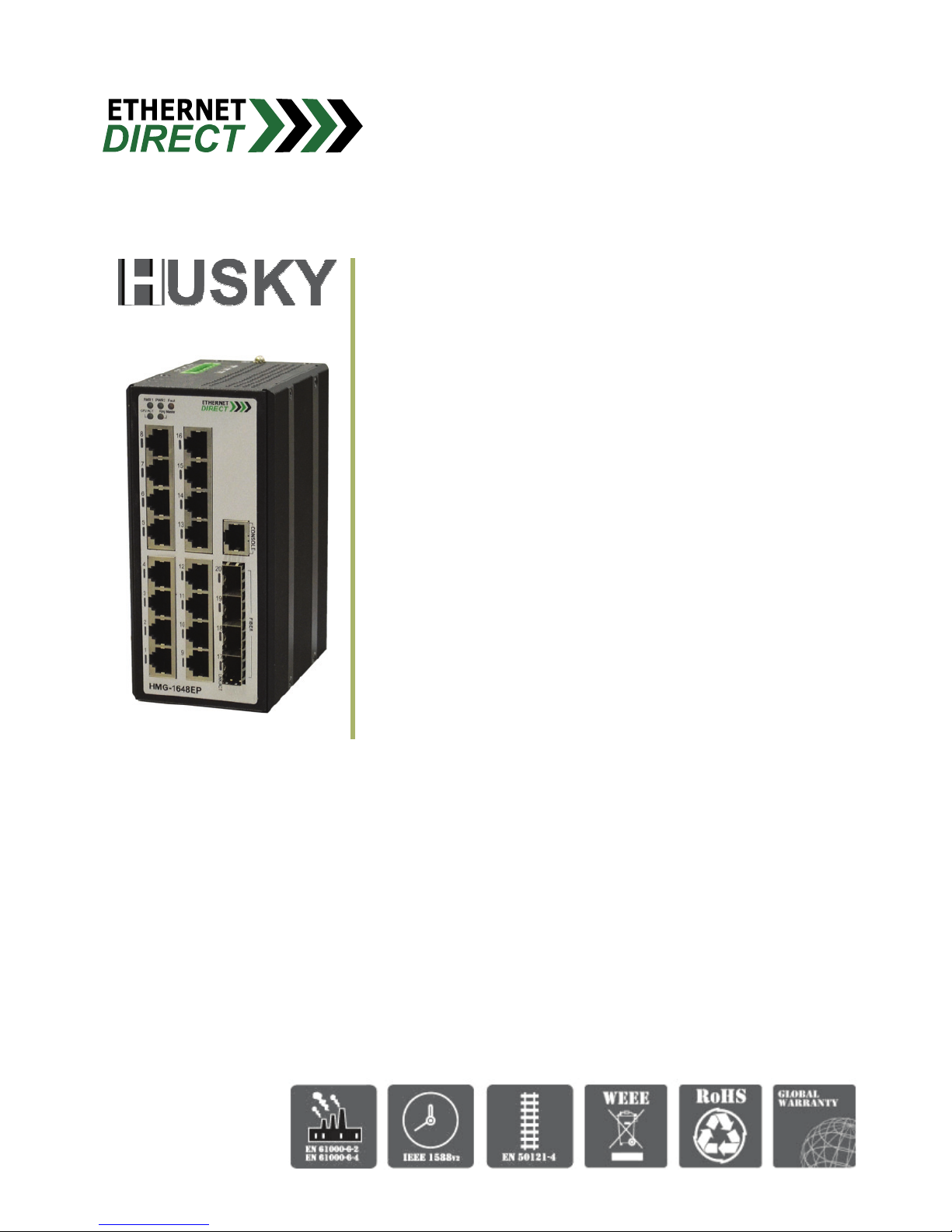
HMG-1648P
HMG-1648EP
Industrial 16 x 10/100Base-T(X) + 4 x
100/1000Base SFP Gigabit Managed
Ethernet Switch
User’s Manual
(Hardware & Installation)
V1.0
06-05-2017

Husky Series Industrial Ethernet Switch Solutions
HMG-1648P & HMG-1648EP Industrial Gigabit Managed Ethernet Switch
User’s Manual (Hardware & Installation)
Copyright Notice
Copyright © 2017 Ethernet Direct Corp.
All rights reserved.
Reproduction in any form or by any means without Ethernet Direct prior written permission is prohibited.

Table of Contents
Chapter 1 Introduction ................................................................................................................................................1-1
1-1 Overview
.......................................................................................................................................................1-1
1-2 Product Feat
ures..........................................................................................................................................1-1
1-3 Package Checkli
st........................................................................................................................................1-2
Chapter 2 Hardware Inst
allation.................................................................................................................................2-1
2-1 Panel Layout.................................................................................................................................................
2-1
2-2 LED Indicators
..............................................................................................................................................2-2
2-3 RJ-45 Port
s...................................................................................................................................................2-2
2-3.1 RJ-45 Pin A
ssignments .....................................................................................................................2-2
2-4 Fiber Port
......................................................................................................................................................2-3
2-5 Console Port
.................................................................................................................................................2-3
2-5.1 Console Cable RJ-45 Pin A
ssignement ............................................................................................2-3
2-5.2 Console Cable DB9 Pin
Assignement ...............................................................................................2-4
2-6 Installing Your Ethernet Direct Switch
..........................................................................................................2-4
2-6.1 Mounting T
he Switch .........................................................................................................................2-4
2-6.2 Wiring The P
ower Input .....................................................................................................................2-5
2-6.3 Wiring The Alarm
Relay.....................................................................................................................2-6
2-6.4 Wiring the Earth Ground
....................................................................................................................2-6
2-6.5 Ethernet Cabling
................................................................................................................................2-7
Appendix A Specifications
......................................................................................................................................... A-1
Appendix B Troubleshooting
..................................................................................................................................... B-1

HMG-1648P & HMG-1648EP Hardware & Installtion 1-1
Chapter 1
Introduction
Welcome to Husky Series HMG-1648P & HMG-1648EP Industrial Gigabit Managed Ethernet Switch. This
chapter includes the following topics:
z Overview
z Product Features
z Package Checklist
1-1 Overview
The HMG-1648EP (extended temperature) and HMG-1648P (standard temperature) are industrial Ethernet
managed switches that comes with 16 x 10/100Base-T(X) ports and 4 Gigabit/Fast Ethernet SFP ports that
provide stable and reliable Ethernet transmission. This powerful switch uses Made in the USA CPU platform for
maximum hardware product reliability. In addition, the enhanced software features support a variety of Ethernet
functions including STP/RSTP/MSTP/ ITU-T G.8032 ERPS and multiple Direct-Ring for redundant cabling, layer
2 Ethernet IGMP, VLAN, Quality of Service, ACL, Security, IPv6, bandwidth control, port mirroring, cable
diagnostic and Green Ethernet.
The HMG-1648EP & HMG-1648P are especially designed for harsh environments with rugged DIN-Rail metal
enclosures to withstand applications where environmental conditions exceed normal product specifications.
Ethernet Direct focuses on mission critical applications and these switches are suitable for industrial networking,
security & surveillance, military & defense, building automation, factory automation, utility market applications
and more. This switch supports standard operating temperature model (-10 to 70°C) and extended operating
temperature range models (-40 to 80°C).
1-2 Product Features
HMG-1648P & HMG-1648EP has the following features:
High Performance Network Switching Technology
z Complies with IEEE standards
z Provides 16 x 10/100Base-T(X) with RJ-45 connector with supporting of Green Ethernet IEEE802.3az EEE
(Energy Efficient Ethernet)
z Provides 4 x 100/1000Base SFP slots with supporting of DDMI
z Supports various network redundant solutions, including Direct-Ring, Direct-Chain, Join-Ring, STP, RSTP,
MSTP and ITU-T G.8032
z Proprietary ultra high speed redundant technology with < 10ms recovery time @ 250 devices
z Supports IEEE1588 PTP V2 for precise time synchronization, to operate in Ordinary-Boundary, Peer to
Peer Transparent Clock, End to End Transparent Clock, Master, Slave mode by each port
z Supports various network security solutions, Port and MAC based IEEE802.1X, RADIUS, ACL, TACACS+,
HTTP/HTTPS, SSL/SSH v2
z Supports DHCP Server/Client/Relay/Snooping/Snooping option 82/Relay option 82
z Network traffic priority, QoS, Traffic classification QoS, CoS, bandwidth control for Ingress/Egress,
broadcast storm control, DiffServ
z Supports IEEE802.1Q VLAN, MAC-based VLAN, IP Subnet-based VLAN, Protocol-based VLAN, VLAN
translation, GVRP/MVRP
z Supports IGMP/MLD snooping V1/V2/V3, IGMP Filtering/Throttling, IGMP query, IGMP proxy reporting,
MLD snooping
z Supports dynamic IEEE 802.3ad LACP Link Aggregation, Static Link Aggregation
z Supports RMON, MIB II, Port mirroring, Syslog, IEEE802.1ab LLDP for network monitoring Supports IPv6
Telnet server, ICMPv6
z Supports CLI, Web based management, SNMP v1/v2c/v3, Telnet server for management
z Supports firmware upgrade via TFTP & HTTP with redundant firmware option
Reliable Power Design
z Equipped with redundant power inputs
z Supports 12 to 48VDC power input
Introduction
HMG-1648P & HMG-1648EP Hardware & Installtion 1-2
z Power reverse polarity protection and overload current protection
Robust Industrial Design
z EN 61000-6-2 and EN 61000-6-4 certified to use in heavy industrial environment
z EN 50121-4 certified for Railway Applications (Track Side)
z Robust industrial design case complies with IP30 housing standard
z Supports operating temperature -10 to 70°C & extended temperature -40 to 80°C
z DIN-Rail or optional wall mounting installation
1-3 Package Checklist
HMG-1648P & HMG-1648EP is shipped with the following items:
z 1 x Husky Series HMG-1648P or HMG-1648EP Industrial Gigabit Managed Ethernet Switch
z 1 x CD (The User’s Manuals are inside the CD)
z 1 x Terminal block
z 1 x Console Cable (RJ-45 to DB9)
z 1 x DIN-Rail mounting kit and 3 x screws
IF DC voltage is supplied by an external circuit, please use a protection device on the power
supply input.

HMG-1648P & HMG-1648EP Hardware & Installtion 2-1
Chapter 2
Hardware Installation
This chapter contains information on HMG-1648P & HMG-1648EP’s appearance and hardware installation.
Topics include:
z Panel Layout
z LED Indicators
z RJ-45 Ports
z Fiber Port
z Console Port
z Installing Your Ethernet Direct Switch
2-1 Panel Layout
Panel Layout of HMG-1648P & HMG-1648EP Industrial Gigabit Managed Ethernet Switch
Front Panel Top Panel
No. Description
1 10/100Base-T(X) RJ-45 ports
2 System LED indicators
3
Terminal block for power and alarm
connections
4 Earth ground connector
5 Console port
6 100/1000Base SFP port
7 RJ-45r port LED indicators
8 Fiber port LED indicators
4
3
1
2
3
4
6
5
7
8

Hardware Installation
HMG-1648P & HMG-1648EP Hardware & Installtion 2-2
2-2 LED Indicators
There are diagnostic LEDs located on the front panel of HMG-1648P & HMG-1648EP. They provide primary
information on switch status as described in the table below.
LED Name LED Color Status Definition
On Power is connected and active at the PWR1/PWR2
PWR1
PWR2
Green
Off Power is off or no power is being supplied to the switch
On
One of the following errors occur:
z Power failure
z UTP port failure
z Fiber port failure
Fault Amber
Off No configurable alarm is active.
CPU Act Green
On
Under normal use, this LED will be active, indicating a healthy
condition of the running CPU.
Ring
Master
Yellow
On
Only turns on when this switch unit is the Ring Master, and all other
units are configured and connected for Direct-Ring or ERPS
(Ethernet Ring Protection Switching or G.8032).
On Port link is up and works in 10M/100M.
RJ-45
Link/Act
Green
Blinking The port is transmitting or receiving packets from a TX device.
On Port link is up and works in 100M.
Green
Blinking The port is transmitting or receiving packets from a TX device.
On Port link is up and works in 1000M.
Fiber SFP
Link/Act
Amber
Blinking The port is transmitting or receiving packets from a TX device.
2-3 RJ-45 Ports
HMG-1648P & HMG-1648EP has 16 10/100Mbps auto-sensing ports for 10Base-T and 100Base-TX devices
connection. Auto MDI/MDIX function allows HMG-1648P & HMG-1648EP to connect to another switch or
workstation without changing straight through or crossover cabling. See RJ-45 Pin Assignment section for
straight through and crossover cable schematic.
2-3.1 RJ-45 Pin Assignments
All ports on HMG-1648P & HMG-1648EP support automatic MDI/MDI-X function, users can use straight-through
cables (see figure below) for all network connections to PCs or servers, or to other switches or hubs. When auto
MDI/MDI-X is enabled, both type of cable can be used and the interface automatically corrects any incorrect
cabling. The table below shows the 10Base-T/100Base-TX MDI and MDI-X port pinouts.
Pin MDI MDI-X
1 Tx+ Rx+
2 Tx+ Rx-
3 Rx+ Tx+
6 Rx- Tx-
Pin MDI MDI-X
1
BI_DA+ BI_DB+
2
BI_DA- BI_DB-
3
BI_DB+ BI_DA+
4
BI_DC+ BI_DD+
5
BI_DC- BI_DD-

Hardware Installation
HMG-1648P & HMG-1648EP Hardware & Installtion 2-3
6
BI_DB- BI_DA-
7
BI_DD+ BI_DC+
8
BI_DD- BI_DC-
Below are the illustrations of straight through connection and cross over connection.
Straight Through Cable Schematic Cross Over Cable Schematic
“+” and “-” signs represent the polarity of the wires that make up each wire pair.
2-4 Fiber Port
HMG-1648P & HMG-1648EP is equipped with 4 x 100/1000Base SFP fiber port gives users more flexibility in
choosing fiber modules to fit the existing network structure on the plant floor.
2-5 Console Port
HMG-1648P & HMG-1648EP has an asynchronous terminal console port for local management via a serial
terminal. The terminal provides management via a CLI (Command Line Interface) which will be familiar to many
networking engineers. For most users, the CLI can be used to initially configure TCP/IP access so that further
configuration can be completed via the GUI (Graphical User Interface) and any web browser.
2-5.1 Console Cable RJ-45 Pin Assignement
This RJ-45 connector provides an RS-232 DCE (data communication equipment) asynchronous serial
connection for local management.
Switch
Tx+ 3
Tx- 6
Rx+ 1
Rx- 2
DD+ 4
DD- 5
DC+ 7
DC- 8
Router or PC
3 Tx+
6 Tx-
1 Rx+
2 Rx-
4 DD+
5 DD-
7 DC+
8 DC-
S
wTxTx
Switch
Tx+ 3
Tx- 6
Rx+ 1
Rx- 2
DC+ 4
DC- 5
DD+ 7
DD- 8
Switch
1 Rx+
2 Rx-
3 Tx+
6 Tx-
7 DD+
8 DD-
4 DC+
5 DC-

Hardware Installation
HMG-1648P & HMG-1648EP Hardware & Installtion 2-4
Pin Ref. Definition Direction
3 TxD Receive Data Out towards DTE
6 RxD Transmit Data In from DTE
5 GND Signal Ground na
2-5.2 Console Cable DB9 Pin Assignement
This DB9 to RJ-45 cable provides a connection for the RS-232. This cable is used between the switch and the
serial port of terminal.
Pins Ref. Definition Direction
2 RxD Receive Data Out from switch towards DTE
3 TxD Transmit Data In to switch from DTE
5 GND Signal Ground na
RJ-45 to DB9 Signal Mapping
DB-9 (Female) RJ-45
Signal Pin
Direction
Pin Signal
RXD 2
3 TXD
TXD 3
6 RXD
GND 5
5 GND
2-6 Installing Your Ethernet Direct Switch
Unpack the HMG-1648P or HMG-1648EP from the packing box. Please refer to Package Checklist section to
see if any item is missing or damaged. The installation steps include:
Mounting The Switch
Wiring The Power Inputs
Wiring The Alarm Relay
Wiring the Earth Ground
Ethernet Cabling.
2-6.1 Mounting The Switch
There are two types of mounting options: DIN-Rail mounting or wall mounting (need to purchase optional wall
mounting accessories). Users can choose the most suitable mounting installation for your own onsite
applications.
2-6.1.1 DIN-Rail Mounting or Wall Mounting
The DIN-Rail mounting kit is come with the box; please check the Package Checklist section for its
contents.
To attach the DIN-Rail or Wall mounting kit:
1. Screw the DIN-Rail or Wall Mount kit to the position shown in the figure below.
2. To detach DIN-Rail or Wall Mount kit from the switch, reverse the step 1.
8 1
CONSOL
PC COM Port
Female

Hardware Installation
HMG-1648P & HMG-1648EP Hardware & Installtion 2-5
+ -
+ -
(DIN-Rail Mount) (Optional Wall Mount)
The switches with DIN-Rail bracket has a steel spring in the upper rail of the bracket. This spring is
compressed for mounting and un-mounting by applying downward force.
.
(Mounting) (Un-Mounting)
2-6.2 Wiring The Power Input
A removable terminal block on the top panel provides both power and alarm connections. This switch supports
dual input from two different DC power sources so that in the event of a single source failure, the switch will
continue to function normally.

Hardware Installation
HMG-1648P & HMG-1648EP Hardware & Installtion 2-6
The two power connections are shown in the above graphic. The device has clearly printed on the case the
locations of the two power inputs, their DC polarity as well as the alarm connection.
2-6.3 Wiring The Alarm Relay
The single electrical relay can be wired into an alarm circuit and under normal condition it is connected as
Normally Closed (will open upon alarm condition). The alarm conditions include power failure, port link up/down
and are user configurable through web user interface. See Alarm Configuration in SNMP
for more information
on configuring alarm relay and triggering fault events.
Please note that the alarm relay contact can only support 1A current at 24VDC (1A@24VDC).
Do not apply
voltage and current that exceed these specifications.
Be sure to disconnect the power cord before installing and/or wiring your switch.
Be sure of the maximum possible current when wiring connections. If the current goes above the
maximum ratings, the wire could overheat and result in serious damage to your switch.
The acceptable wire range is 12 to 24 AWG.
2-6.4 Wiring the Earth Ground
An earth ground connector is provided on the top panel with an earth ground sign next to it. Grounding the device
can help to release leakage of electricity to the earth safely so as to reduce injuries from electromagnetic
interference (EMI).
Prior to connecting to the power, it is important to connect the ground wire to the earth. Follow steps below to
install ground wire:
1. Loosen or remove the grounding screw.
2. Attach the grounding screw to the ring-type or fork-type terminal of the grounding cable. Make sure that the
grounding cable is long enough to reach the earth.
3. Use a screwdriver to fasten the grounding screw.
Fault
Normally Closed (NC)

Hardware Installation
HMG-1648P & HMG-1648EP Hardware & Installtion 2-7
2-6.5 Ethernet Cabling
For RJ-45 port connection, prepare twisted-paired, straight through Category 5/5e or above cables for Ethernet
connection. The linking distance between the switch and the network device must be less than 100 meters (328
ft.).
For 10Mbps connections, use 100Ω Category 3, 4 or 5 cables.
For 100Mbps connections, use 100Ω Category 5/5e cables.
The UTP port (RJ-45) LED(s) on the switch will light up when the cable is connected with the network device.
Please refer to the LED Indicators section for more information.
Before connecting any network device, make sure network devices support auto MDI/MDI-X.
If not support, use the cross over Category 5/5e cables.
After all wiring and connection are done and the LED lights on the switch’s front panel show normal status, the
hardware installation is complete.
Ring-type
terminal
Fork-type
terminal

HMG-1648P & HMG-1648EP Hardware & Installtion A-1
Appendix A
Specifications
HMG-1648P & HMG-1648EP Product Specifications are as follows:
Hardware
Interface
RJ-45 Ports 16 x 10/100Base-T(X) auto-negotiation speed, Full/Half duplex, auto MDI/MDI-X
Fiber Ports 4 x 100/1000Base SFP slots
Console Port RS-232 (RJ-45 interface)
Per Unit Power 1 (Green), Power 2 (Green), Fault (Amber), CPU Act
(Green), Ring, Master (Yellow)
RJ-45 Port 10/100 Link/Active (Green)
LEDs
Fiber Port 100 Link/Active (Green), 1000 Link/Active (Amber)
Alarm Contact 1A@24VDC
Power Requirement
Power Input 12-48VDC, redundant power with removable terminal block
Power Protection Power reverse polarity protection and overload current protection
Power Consumption 12VDC/10.8W, 24VDC/10.6W, 48VDC/12.5W
Physical
Dimensions IP30 standard, 72mm (W) x 152mm (H) x 106mm (D)
Installation DIN-Rail or optional wall mounting
Environmental
Operating Temp
Regular: -10 to 70°C (HMG-1648P)
Extended: -40 to 80°C (HMG-1648EP)
Storage Temp -40 to 85°C
Operating Humidity 5% to 95% RH (non-condensing)
Technical
Standards
IEEE 802.3 10Base-T Ethernet
IEEE 802.3u 100Base-TX/100Base-FX
IEEE 802.3z Gigabit Fiber
IEEE 802.3x Flow Control
IEEE 802.3ad Port trunk with LACP
IEEE 802.3ac VLAN Tagging extension (Max. frame size extended to 1522 Bytes)
IEEE 802.3az EEE (Energy Efficient Ethernet)
IEEE 802.1D Spanning Tree
IEEE 802.1w Rapid Spanning Tree
IEEE 802.s Multiple Spanning Tree
IEEE 802.1p Class of Service
IEEE 802.1Q VLAN Tagging
IEEE 802.1X User Authentication (Radius)
IEEE 802.1AB LLDP
ITU-T G.8032 / Y.1344 ERPS (Ethernet Ring Protection Switching)
Network Media 10Base-T 2-pair UTP/STP Cat. 3, 4, 5/5e cables

Specifications
HMG-1648P & HMG-1648EP Hardware & Installtion A-2
EIA/TIA-568 100Ω (100m)
100Base-TX 2-pair UTP/STP Cat. 5/5e cables
EIA/TIA-568 100Ω (100m)
100/1000Base SFP 50/125um~62.5/125um (Multi-mode)
9/125um (Single-mode)
Protocols CSMA/CD
Switching Architecture Store and Forward
Regulatory Approvals
EMC CE, EN 61000-6-2, EN 61000-6-4
EMI FCC Part 15 Subpart B Class A,CE EN55022 Class A
EMS
EN 61000-4-2
EN 61000-4-3
EN 61000-4-4
EN 61000-4-5
EN 61000-4-6,
EN 61000-4-8
Safety UL 60950-1
Railway Application (Track Side) EN 50121-4 (Certified)
Shock IEC60068-2-27
Vibration IEC60068-2-6
Free Fall IEC60068-2-32
Environmental WEEE, RoHS
MTBF 419,048 hours based on Mil-Hdbk-217F, GB
Warranty 5 years
Software Specification
Redundancy
Direct-Ring, Direct-Chain, Join-Ring < 10ms recovery time,
(Each switch can configure up to 5 rings regardless of Direct-Ring, Direct-Chain,
Join-Ring, and each ring can contents 250 units of switches), supports loop protection
STP/RSTP/MSTP
ITU-T G.8032 / Y.1344 ERPS with < 50ms recovery time
(Single Ring, Sub-Ring, Multiple ring topology networks)
Link Aggregation: Static supports up to 10 trunk groups
Dynamic (IEEE 802.3ad LACP) supports up to 10 trunk groups
VLAN
VID 1 to 4094
VLAN group up to 4094 groups
IEEE 802.1ad Q-in-Q
MAC-based VLAN (256 entries)
IP Subnet-based VLAN (128 entries)
Protocol-based VLAN (Ethernet, SNAP, LLC), (128 entries)
VLAN Translation (256 entries)
GVRP (GARP VLAN Registration Protocol)
MVR (Multicast VLAN Registration)
QoS
Port based and IEEE 802.1p based CoS
QoS determined by port, per port 8 active priorities queues
IP Precedence based Co, IP DSCP based CoS

Specifications
HMG-1648P & HMG-1648EP Hardware & Installtion A-3
DiffServ (RFC 2474) Remarking
Bandwidth Control Ingress/Egress
Storm Control Unicast, Broadcast, Multicast
IGMP/MLD Snooping
IGMP Snooping v1/v2/v3, MLD Snooping v1/v2
Port Filtering Profile
Throttling, Fast Leave
Maximum Multicast Group: Up to 1022 entries
Query / Static Router Port
Security
IEEE 802.1X (Port-based, MAC-based), RADIUS, TACACS+ 3.0
Supports ACL, no. of rules up to 256 entries
HTTP/HTTPS, SSL, SSH v2
Local Authentication
Remote Access Security: RADIUS, TACACS+
Management interface access filtering via Web, Telnet/SSH, CLI console
Management
SNMP, Web, Telnet/SSH, CLI management
TFTP/HTTP backup/restore configurations
Firmware upgrade via TFTP/HTTP, supports dual firmware
RMON I (1, 2, 3, 9 group), RMON II
RFC1213 MIB II, Private MIB
Supports UPnP, IP Source Guard, Port Mirroring
Warning message sends to syslog, e-mail, alarm relay
DNS Client, Proxy
LLDP: LLDP-MED
System Log Supports local system log and remote Syslog server
DHCP
Server, Client, Relay, Snooping
Snooping option 82, Relay option 82
Time Management
IEEE1588 PTP V2: Ordinary-Boundary, Peer to Peer Transparent Clock, End to End
Transparent Clock, Master, Slave
NTP/SNTP Client
IPv6
IPv6 Management Telnet Server/ICMP v6
SNMP over IPv6, HTTP over IPv6, SSH over IPv6, IPv6 Telnet, IPv6 NTP (Client), IPv6
SNTP (Client), IPv6 TFTP, IPv6 QoS, IPv6 ACL (256 entries)
Green Ethernet
Supports IEEE802.3az EEE (Energy Efficient Ethernet): Management to optimize the
power consumption
Determine the cable length and lowering the power for ports work with short cable
Lower the power for a port when there is no link
LED Power Management: Adjustment on LEDs intensity
Cable Diagnostic: (Copper ports
only)
Shows physical status of the UTP cable, in order to get more accurate result the cable
length suggestion is 7-140 meters

HMG-1648P & HMG-1648EP Hardware & Installtion B-1
Appendix B
Troubleshooting
Select the proper UTP cables to construct your network. Please check that you are using the
right cables. Use unshielded twisted-pair (UTP) or shield twisted-pair (STP) cables for RJ-45
connections: 100Ω Category 3, 4 or 5 cables for 10Mbps connections and 100Ω Category
5/5e cables for 100Mbps connections. Also be sure that the length of any twisted-pair
connection does not exceed 100 meters (328 feet).
Diagnostic LED indicators located on the front panel of the switch can help users to easily
monitor the switch.
IF the power indicator does not light on when the power cord is plugged in, you may have a
problem with power cord. Then check for loose power connections, power losses or surges at
power outlet. IF you still cannot resolve the problem, contact your local dealer for assistance.
If the switch LED indicators are normal, the cables are connected correctly, and the packets
still cannot transmit, please check your system’s Ethernet devices’ configuration or status.
 Loading...