

Page 1

Chapter
Chapter
Chapter
CommuniCations
6
6
6
In This Chapter...
Communications: Capabilities ................................................................................... 6-3
Communication Ports ............................................................................................... 6-3
Communications: Connectivity ............................................................................... 6-11
Communication Ports ............................................................................................. 6-11
Communications ASCII and Custom Protocol Functionality .................................. 6-17
ASCII Instructions ................................................................................................... 6-17
Custom Protocol Instructions ................................................................................. 6-18
Communications: Ethernet ...................................................................................... 6-20
TCP and UDP Port Numbers .................................................................................. 6-20
IP Addressing and Subnetting ................................................................................ 6-20
PC Setup ................................................................................................................ 6-21
CPU Setup .............................................................................................................. 6-22
TCP Connection Behavior with Modbus TCP and Network Instructions ................. 6-23
Communications Modbus Functionality ................................................................. 6-24
Master/Client Function Code and Data Type Support ............................................ 6-24
Slave/Server Function Code and Data Type Support .............................................. 6-26
Assigning Modbus Addresses to Tags ..................................................................... 6-27
Modbus Options .................................................................................................... 6-30
Modbus Instructions ............................................................................................... 6-33
Network Instructions .............................................................................................. 6-35
Automatic Poll versus Manual Polling and Interlocking ........................................... 6-36
Message Queue ...................................................................................................... 6-38
EtherNet/IP for the Productivity Series ................................................................. 6-39
Terminology Definitions ......................................................................................... 6-39
Network Layer Chart .............................................................................................. 6-40
EtherNet/IP Data .................................................................................................... 6-40
Page 2

Chapter 6: Communications
Productivity
3000
Class 1 and Class 3 Connections ............................................................................ 6-41
Example Setup: Productivity3000® as EtherNet/IP Adapter ..................................... 6-41
Troubleshooting Tips: ............................................................................................. 6-47
Ethernet IP I/O Message Troubleshooting: .............................................................. 6-49
Ethernet IP Explicit Message Troubleshooting: ........................................................ 6-49
Communications: Remote I/O and GS-Drives ........................................................ 6-50
Things To Consider for the design of Remote I/O and GS-Drives ............................ 6-50
Configuration of Remote Slaves .............................................................................. 6-51
Configuration of GS-Drive Connections .................................................................. 6-54
Communications: Port Configuration ..................................................................... 6-58
Ethernet Configuration ........................................................................................... 6-58
External Ethernet Port Settings ............................................................................... 6-59
Local Ethernet Port Settings.................................................................................... 6-60
Remote Access Configuration ................................................................................. 6-60
Serial Configuration ................................................................................................ 6-61
RS-232 and RS-485 Port Settings ............................................................................ 6-61
Communications: Error Codes ................................................................................ 6-64
P3000 EtherNet/IP Error Codes ............................................................................. 6-65
ii
NOTE: The P3-RS module is discontinued as of 6/20. Please use P3-RX as a replacement.
Hardware User Manual, 4th Edition, Rev. M
Page 3
Productivity
3000
Communications: Capabilities
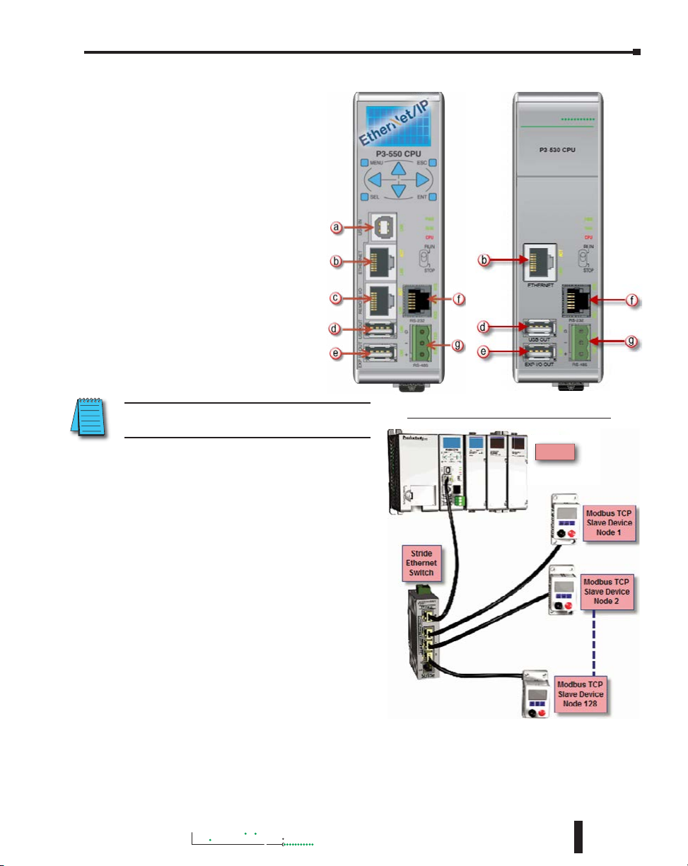
Communication Ports
The AutomationDirect P3000
CPUs are provided with several
Communications Ports. Each of
these ports are described in the
sections below.
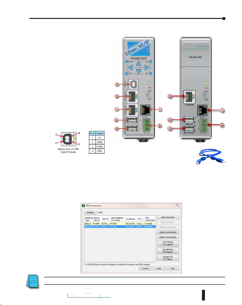
a. USB IN: The USB IN
programming port is a USB
Type B style connector
located on the upper left
side of the CPU. It is used
exclusively for connecting to a
PC running the Productivity
Suite Programming
Software. Installing the
programming software will
install the USB driver as
well. See Communications:
Connectivity section for
connection information.
Chapter 6: Communications
NOTE: The USB IN port is NOT compatible with
older 1.0/1.1 full speed USB devices.
b. Ethernet: The Ethernet port is 10/100
Base-T Ethernet with an RJ-45 style
connector. It is used for:
• Connection to a PC running the
Productivity Suite programming
software.
• Modbus TCP Client connections
(Modbus requests sent from the
CPU).
• Modbus TCP Server connections
(Modbus requests received by the
CPU).
• Outgoing Email.
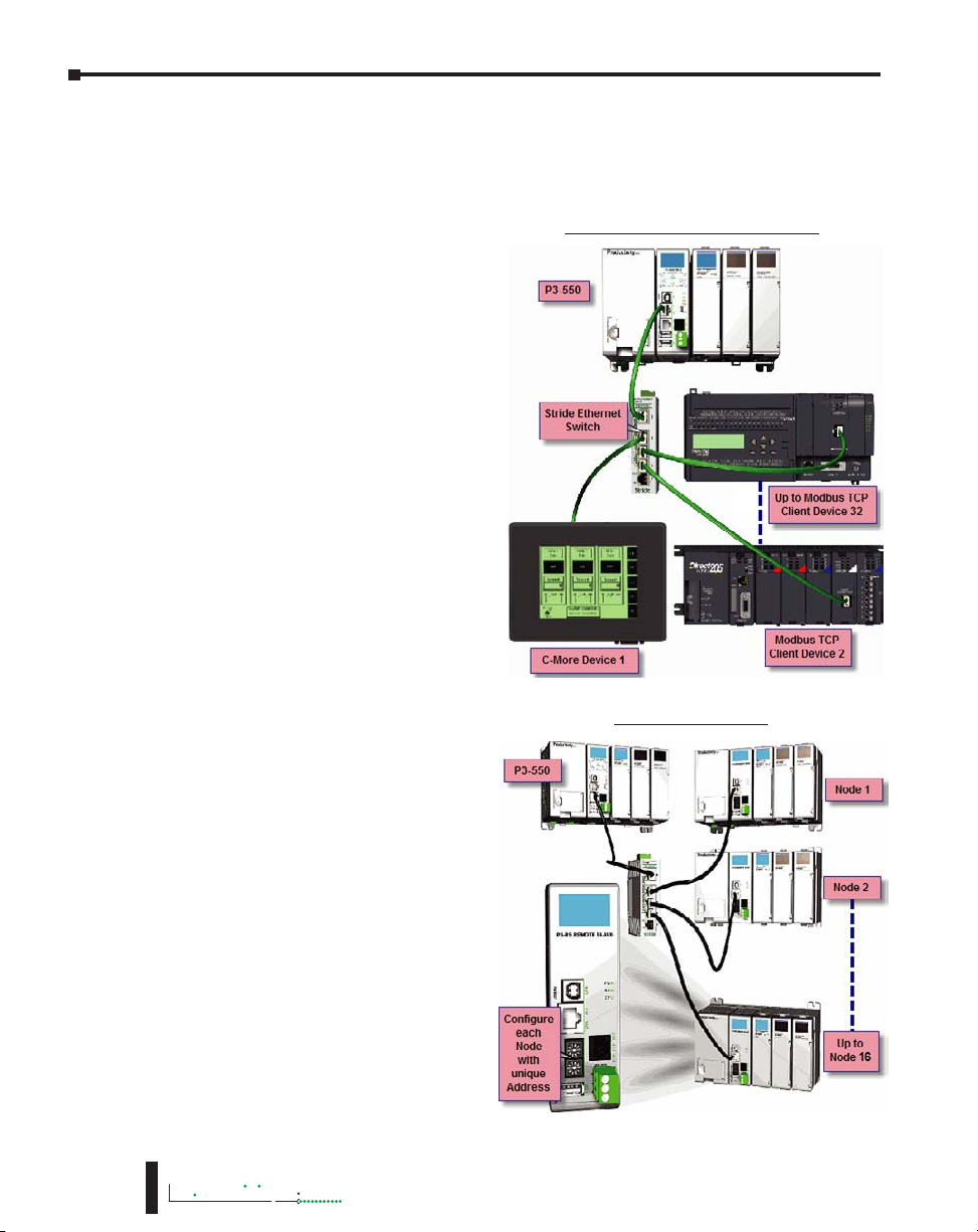
Modbus TCP Client connections: The
CPU can connect to 32 Modbus TCP
server devices concurrently by means
of communications instructions in the
ladder program (MRX, MWX, RX, WX).
It is possible to connect to more than
32 Modbus TCP server devices, but not
concurrently.
This is accomplished by having communications instructions for more than 32 devices in the
ladder program and controlling the enabling and disabling of the instructions so that only 32
devices are enabled at a given time. To connect to non Productivity3000
(Modbus Read) and MWX (Modbus Write) instructions. To connect to other P3000 CPU’s, use
the RX (Network Read) and WX (Network Write) instructions.
Modbus TCP Client (MRX-MWX)
P3-550(E)
®
devices, use the MRX
Hardware User Manual, 4th Edition, Rev. M
6-3
Page 4
Chapter 6: Communications
Productivity
The greatest difference between the RX and the MRX is the RX Tag Name in the target CPU
can be referenced directly and does not need a corresponding Modbus address. The way this
is accomplished is by mapping local and remote tagnames together within the local CPU’s
RX instruction. Once the instruction is set up to read a remote project, the “Tags of Remote
Project” or “Array Tags of Remote Project” drop down lists will be accessible. Map the Tag of
the Remote project to a Tag in the Local project to read this data.
Modbus TCP Server connections: The
CPU can serve data back to 32 Modbus
TCP Client devices concurrently. If
32 Modbus TCP Client devices are
connected to the CPU, then any new
TCP connection requests will be
denied until one of the existing 32
devices drops its connection. If the
Client device connecting to the CPU
is not a Productivity3000
a Modbus address must be assigned
to the tag that is being requested.
This is done in the Tag Database
window. If the device connecting to
the CPU is another P3000 CPU or
C-more panel, no Modbus address is
required. See Communications Port
Configuration for port configuration,
Communications: Connectivity section
for connection information and
Communications: Ethernet section for
Ethernet set up.
c. Remote I/O: The Remote I/O port
is 10/100Base-T Ethernet with an
RJ-45 style connector. It is used for
connecting to a Remote I/O network
consisting of P3-RS or P3-RX Remote
Slaves and/or GS-EDRV100 units with
GS-drives.
Remote Slaves: The P3-550(E) and
P3-550E CPUs can connect with up
to 16 P3-RS/RX Remote Slaves. The
P3-550(E)/E will auto detect all P3-RS/
RX units that are configured with
unique station addresses (by means
of two rotary switches on the front
of the module). The configuration
can be managed in the Hardware
Configuration in the Productivity
Suite Programming Software. See
Communications Remote I/O and GS
Drives for configuration information
and Communications: Connectivity
section for connection information.
®
device, then
Modbus TCP Client (RX-WX)
Remote I/O Slaves
6-4
3000
Hardware User Manual, 4th Edition, Rev. M
Page 5
Chapter 6: Communications
Productivity
3000
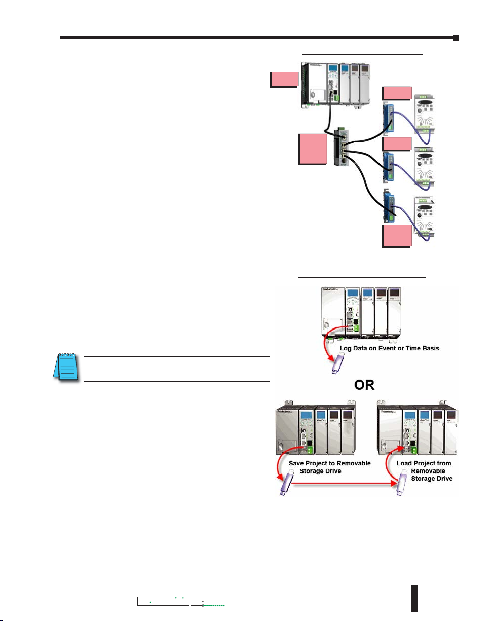
Remote GS1 (GS-EDRV100)
GS Drive Devices: The P3-550(E) CPU
can connect to up to 32 GS-EDRV100
Modules. The P3-550(E) will auto
detect all GS-EDRV100 modules that
have a unique address (configured by
the bank of dipswitches on the module).
The configuration can be managed
in the Hardware Configuration in
the Productivity Suite programming
software. See Communications:
Remote I/O and GS Drives section
for configuration information and
Communications: Connectivity section
for connection information.
d. USB OUT: The USB OUT data port
is the upper port of two USB 2.0 Type
A connectors on the CPU. The USB
OUT port uses a SDCZ4-2048-A10 Pen
Drive (may work with other pen drives)
for data logging only in the P3-530 or for
data logging and project transfers in the
P3-550(E).
NOTE: The USB OUT port is NOT compatible with
older 1.0/1.1 full speed USB devices.
P3-550
Stride
Ethernet
Switch
USB Removable Storage Drive
Node 1
Node 2
Up to
Node 32
Project Transfer (P3-550(E) only): For
security, this feature is disabled by default
when creating a new project. It can be
enabled in the Hardware Configuration
panel for the P3-550(E). Once enabled,
projects may be transferred between a
CPU and Removable Storage Device,
or between a Removable Storage Device
and PC. Files stored on the Removable
Storage Device by a P3-550(E) or the
Productivity Suite programming software
are stored under a default name, so only
one project may be handled at a time on a Removable Storage Device. Existing projects on the
Removable Storage Device will be overwritten without a prompt.
Data Logging: The Data Logger tool allows setup of periodic or event-based data logging of tag
and System Errors to the Removable Storage Drive. Data Logger setup is accessed under the
Monitor & Debug Menu. See Communications: Connectivity section for more information.
Hardware User Manual, 4th Edition, Rev. M
6-5
Page 6
Chapter 6: Communications
Productivity
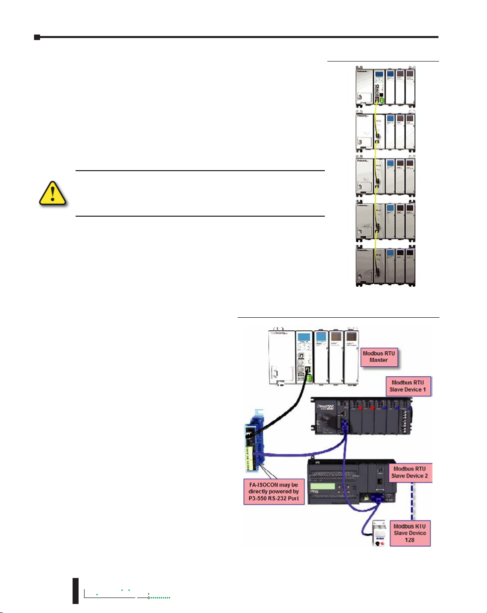
e. EXP I/O OUT: The Expansion I/O port is the lower port
of two USB 2.0 Type A connectors on the CPU. The EXP
I/O Out port is only used for connections to local P3-EX
modules in a Productivity3000
I/O is treated as local I/O by the CPU and is completely scansynchronous. The I/O is automatically detected on power up.
CAUTION: This port is ONLY for Expansion I/O. The signal pins on
this port are NOT standard USB. DO NOT USE A USB REPEATER
TO EXTEND THE RANGE OF THIS PORT. See Communications
Connectivity for more information.
®
base with I/O. Expansion
P3-EX Expansion Network
6-6
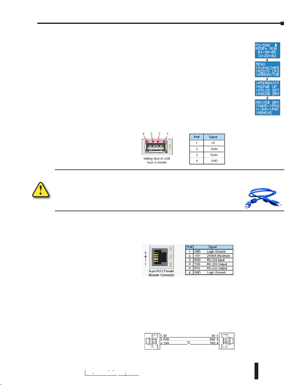
f. RS-232: The RS-232 port is an
RJ-12 connector located on the right
side of the CPU. This port can be
used for:
• Modbus RTU Master
connections.
• Modbus RTU Slave connections.
• ASCII Incoming and Outgoing
communications.
• Custom Protocol Incoming and
Outgoing communications.
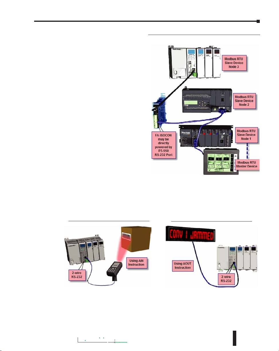
Modbus RTU Master connections:
The RS-232 port is intended to be
used for point-to-point connections
but it is possible to connect up to 128
devices on a network if a RS-232 to
RS-485/422 converter is connected
to the port (such as a FA-ISOCON).
This is accomplished by using the
communications instructions in the
ladder project (MRX, MWX, RX,
WX). If 4-wire RS-485 or RS-422
communications is needed, using
this port with an FA-ISOCON is the
best method. See Communications:
Connectivity section for more
information.
3000
Hardware User Manual, 4th Edition, Rev. M
RS-232 Modbus RTU Master Network Topology
Page 7
Productivity
3000
Modbus RTU Slave connections: The
RS-232 port is intended to be used
for point-to-point connections but
it is possible for the RS-232 port to
be used on a Modbus RTU network
by using a RS-232 to RS-485/422
converter. The port is addressable
in the Hardware Configuration in
the Productivity Suite programming
software. It is important to note that
the RS-232 port cannot be a Modbus
RTU master and slave concurrently.
If the port is set to Modbus RTU
and there are no communications
instructions (MRX, MWX, RX, WX) in
the project, the CPU will automatically
respond to Modbus requests from a
Modbus master. See Communications:
Connectivity section for more
information.
Chapter 6: Communications
RS-232 Modbus RTU Slave Network Topology
ASCII Incoming and Outgoing communications: The RS-232 port can be used for sending and
receiving non-sequenced String data. This feature is typically used for receiving bar code strings
from a scanner or sending statistical data to a terminal or serial printer using the ASCII IN and
ASCII OUT instructions. See Communications: Connectivity section for more information.
RS-232 ASCII In Communication
Hardware User Manual, 4th Edition, Rev. M
RS-232 ASCII In Communication
6-7
Page 8
Chapter 6: Communications
Productivity
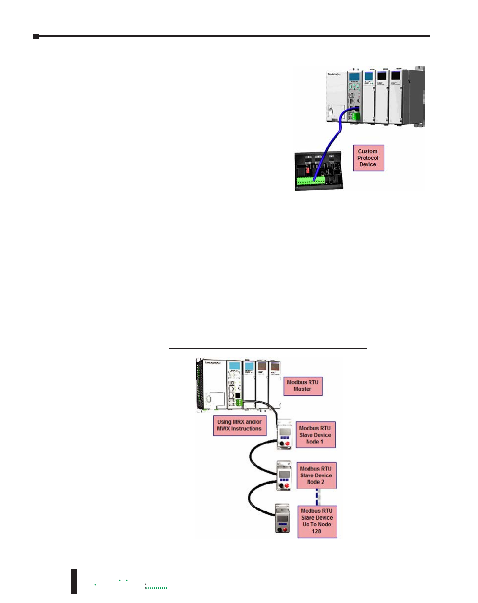
Custom Protocol Incoming and Outgoing
communications: The RS-232 port can be used for
sending and receiving non-sequenced byte arrays
to various devices. This function is typically used
for communicating with devices that don’t support
the Modbus protocol but have another serial
communications protocol. This is accomplished by
using the Custom Protocol In and Custom Protocol
Out instructions. The RS-232 port is intended
to be used for point-to-point connections but it is
possible for the RS-232 port to be used on a multinode network by using a RS-232 to RS-485/422
converter. See Communications: Connectivity for
more information.
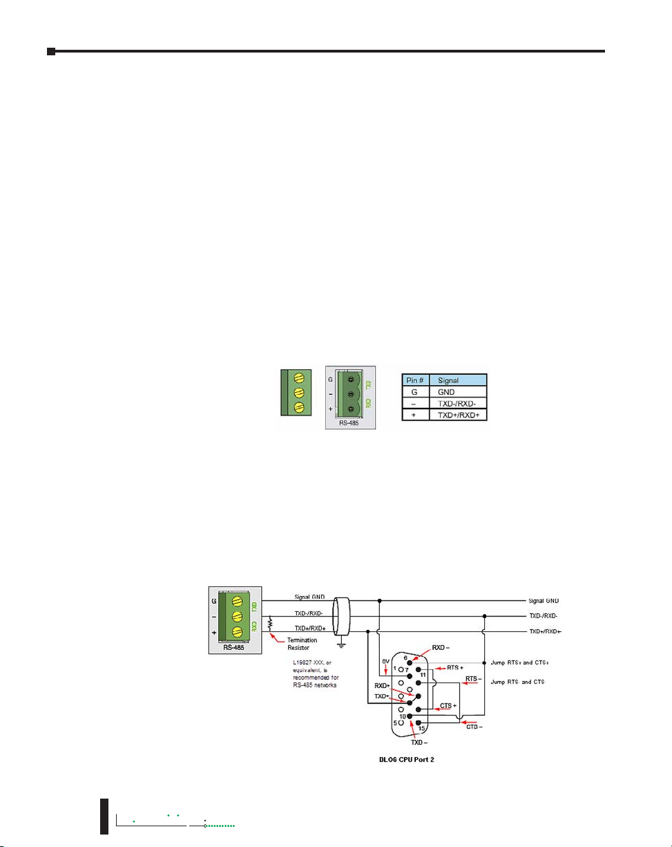
g. RS-485: The RS-485 port is a 3-pin removable terminal block. The RS-485 port can be used for:
• Modbus RTU Master connections.
• Modbus RTU Slave connections.
• ASCII Incoming and Outgoing communications.
• Custom Protocol Incoming and Outgoing communications.
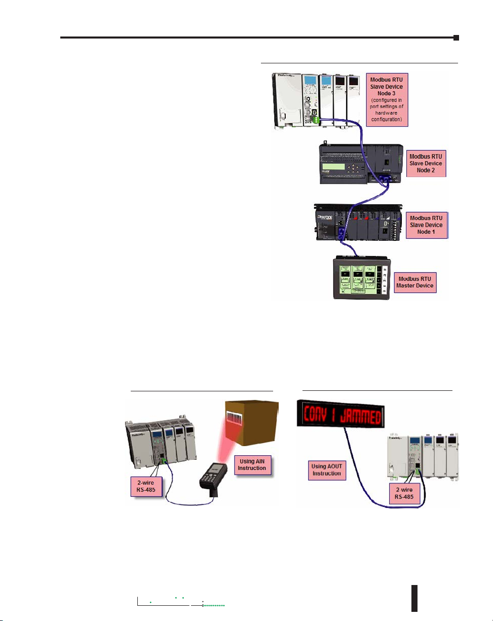
Modbus RTU Master connections: The RS-485 network port is used for multi-node networks.
The CPU can connect to 128 Modbus RTU slave devices on a network. This is accomplished
by using the communications instructions in the ladder project (MRX, MWX, RX, WX). See
Communications: Connectivity section or more information.
RS-232 Custom Protocol In and Out
6-8
3000
RS-485 Modbus RTU Master Network Topology
Hardware User Manual, 4th Edition, Rev. M
Page 9
Chapter 6: Communications
Productivity
3000
RS-485 Modbus RTU Slave Network Topology
Modbus RTU Slave connections:
The RS-485 network port is used
for multi-node networks. The
port is addressable in the Hardware
Configuration in the Productivity
Suite programming software. If
the port is set to Modbus RTU
and there are no communications
instructions (MRX, MWX, RX,
WX) in the project, the CPU will
automatically respond to Modbus
requests from a Modbus master. See
Communications Connectivity for
more information.
ASCII Incoming and Outgoing communications: The RS-485 port can be used for sending and
receiving non-sequenced String data. If long distances are required between the ASCII device
and the CPU, the RS-485 port is the better selection because of its increased distance support
(1,000 meters). ASCII communications are typically used for receiving bar code strings from a
scanner or sending statistical data to a terminal or serial printer using the ASCII IN and ASCII
OUT instructions. See Communications: Connectivity section for more information.
RS-485 ASCII In Communication
RS-485 ASCII Out Communication
Hardware User Manual, 4th Edition, Rev. M
6-9
Page 10
Chapter 6: Communications
Productivity
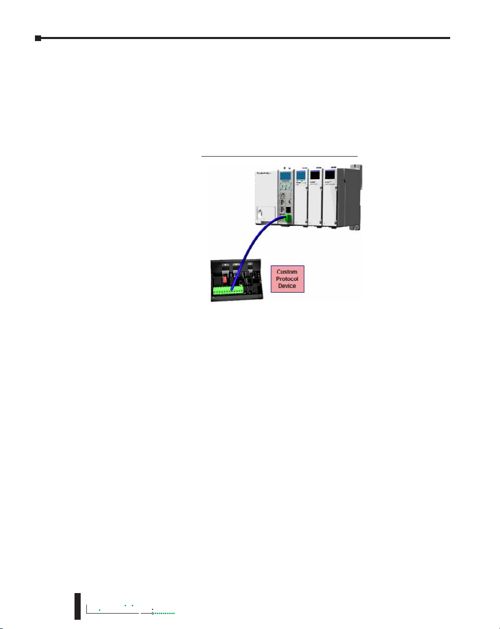
Custom Protocol Incoming and Outgoing communications: The RS-485 port can be used for
sending and receiving non-sequenced byte arrays to various devices. This function is typically
used for communicating with devices that don’t support the Modbus protocol but have another
serial communications protocol. If long distances are required between the device and the CPU,
the RS-485 port is the better selection because of its increased distance support (1,000 meters).
This feature is accomplished by using the Custom Protocol In and Custom Protocol Out
instructions. See Communications: Connectivity section for more information.
RS-485 Custom Protocol In and Out
6-10
3000
Hardware User Manual, 4th Edition, Rev. M
Page 11
Productivity
3000
Communications: Connectivity
Communication Ports
The AutomationDirect P3000
CPUs are designed with several
Communications Ports, seven
communications ports on the
P3-550, six on P3-550E, and five
communications ports on the
P3-530. The connectivity for
each of these ports is described
in the sections below. The
Communication Ports available
are:
a. USB IN Port (P3-550
only): Programming port
with a USB Type B female
connector.
This port requires a USB Type A-B cable
(such as the P3-EX-CBL6 cable).
Chapter 6: Communications
The USB Port is the simplest method of connecting the Productivity Suite programming
software to the P3-550 CPU. After the programming software has been installed, connect a
USB A to B cable from the PC to the CPU. Once the software has been opened, click on CPU
and select the “Choose CPU” option. The dialog shown below will appear.
Highlight the CPU listed in the dialog box and click on “Connect”. No configuration is
required.
NOTE: The USB IN port is NOT compatible with older 1.0/1.1 full speed USB devices.
Hardware User Manual, 4th Edition, Rev. M
6-11
Page 12
Chapter 6: Communications
Productivity
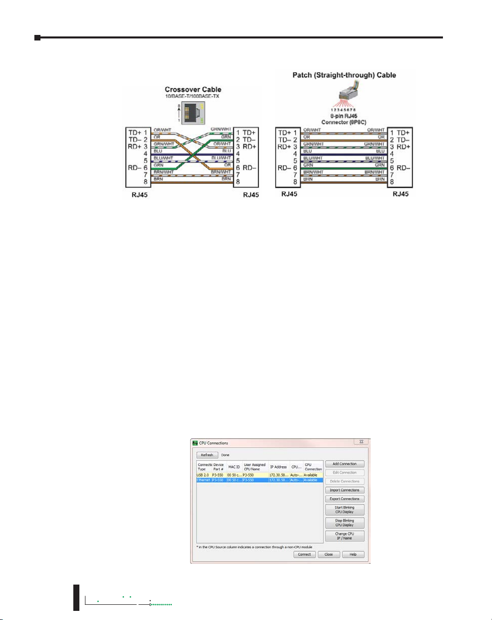
b. Ethernet Port: Programming and Modbus TCP Client/Server port with 10/100 Base-T
Ethernet RJ45 connector.
• General Information:
Crossover cables can be used to directly connect two endpoint Ethernet devices such as a
PC network interface card and the CPU. Patch (or Straight-through) cables are used to
connect an endpoint Ethernet device to an Ethernet switch.
The maximum distance for one cable or segment is 100 meters (328 feet). If the
distance required between 2 devices is greater than 100 meters, add an Ethernet switch to
extend the distance. An Ethernet switch can be added every 100 meters (or less) almost
indefinitely. Each Ethernet switch added will incur some latency (actual amount differs
between switches and manufacturers). So if a very long distance is needed between 2
Ethernet devices, it may be better to convert to fiber optics.
The External Ethernet Port can be used as a programming port, a Modbus TCP Client
port, a Modbus TCP Server port, or to communicate to other P3000 CPUs. The
External Ethernet Port can also be used to send emails using the EMAIL instruction.
• Create a Connection:
To communicate with the Productivity Suite programming software, connect a crossover
Ethernet cable from the PC to the CPU External Ethernet Port or connect a patch
(straight-through) Ethernet cable from the PC to an Ethernet switch and another patch
cable from the Ethernet switch to the External Ethernet Port. Once the software has been
opened, click on CPU and select the “Choose CPU” option. The dialog shown below will
appear.
6-12
3000
Hardware User Manual, 4th Edition, Rev. M
Page 13
Chapter 6: Communications
Productivity
3000
Highlight the CPU that you wish to connect to and press the “Connect” button. You may
see CPUs that are not on the same subnet as your PC within the CPU Connections dialog
box, but this does not mean you can connect to them. To connect to the CPU, you must
configure either your PC or your CPU to be in the same subnet. You can easily change the
Ethernet settings of the CPU by highlighting it and selecting the “Change CPU IP/Name”
button (shown below). Or if you prefer, the PC Setup section of this chapter contains
information on configuring the Ethernet settings of your PC.
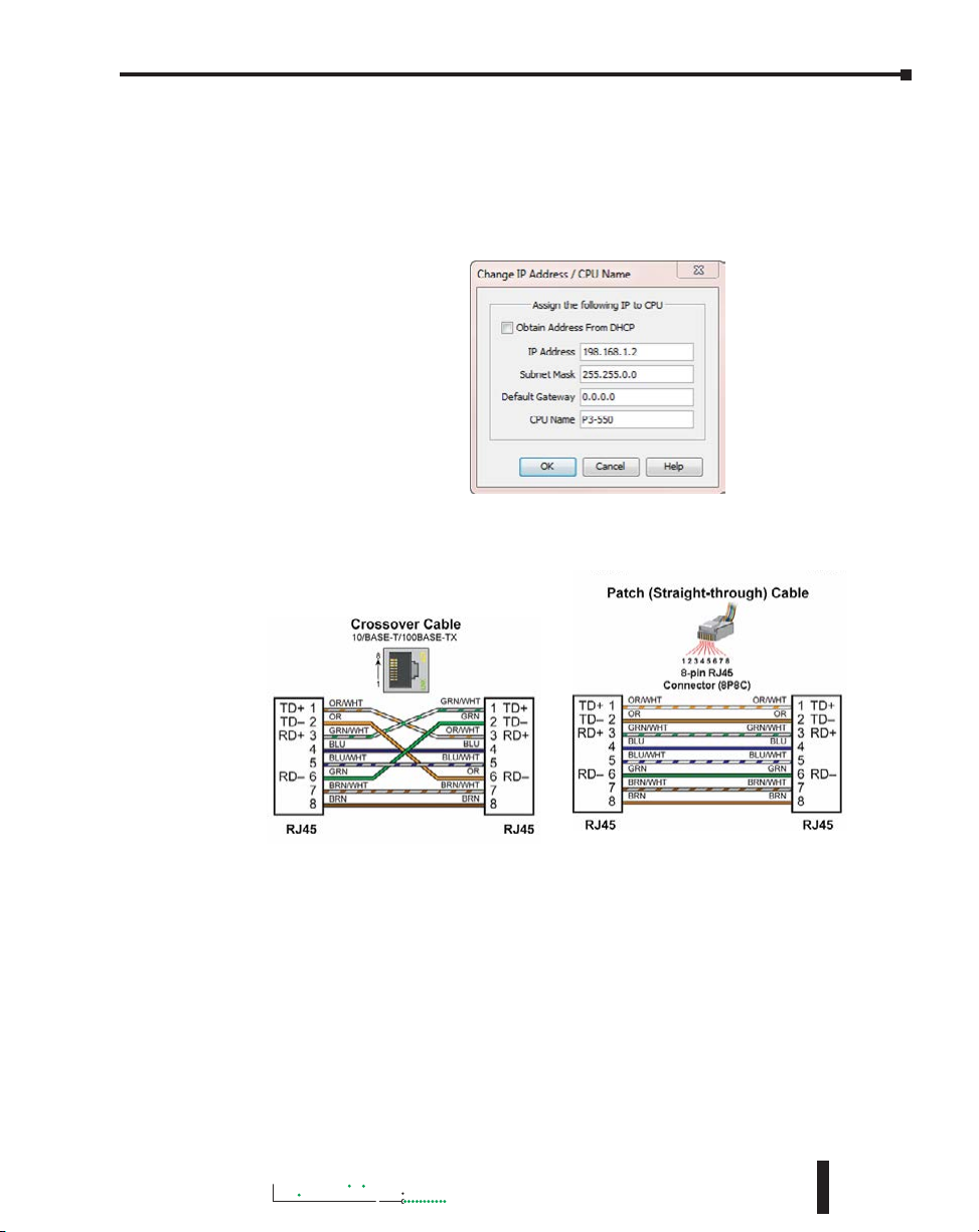
c. Remote I/O Ethernet Port (P3-550(E) only): P3-RS/RX Remote Slave and/or
GS-EDRV100 Drive Ethernet RJ45 connector.
Crossover cables can be used to directly connect endpoint Ethernet devices and the CPU.
For example, connecting a P3-RS or P3-RX Remote Slave Module to the P3-550(E)
CPU. Patch (or Straight-through) cables are used to connect an endpoint Ethernet device
to an Ethernet switch.
The maximum distance for one cable or segment is 100 meters (328 feet). If the
distance required between 2 devices is greater than 100 meters, add an Ethernet switch to
extend the distance. An Ethernet switch can be added every 100 meters (or less) almost
indefinitely. Each Ethernet switch added will incur some latency (actual amount differs
between switches and manufacturers). So if a very long distance is needed between 2
Ethernet devices, it may be better to convert to fiber optics.
The Remote I/O Ethernet Port is used to communicate to the Remote I/O Network,
consisting of Remote Slave bases (P3-RS/RX modules) and GS Drives with a
GS-EDRV100 Ethernet module. It is highly recommended that the network attached to
this port be isolated from other networks and it is absolutely necessary that it be isolated
from other Remote I/O networks. See Remote I/O and GS Drives topic for details.
Hardware User Manual, 4th Edition, Rev. M
6-13
Page 14
Chapter 6: Communications
Productivity
NOTE: USB Project Transfers are NOT supported by the P3-530 CPU.
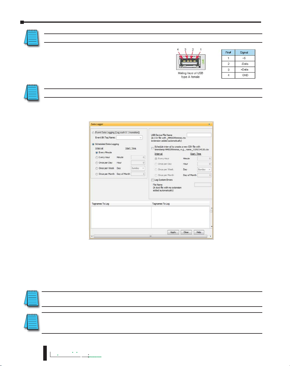
d. USB OUT Port: USB Port for Data logging or
project transfer with USB 2.0 Type A connector.
This Port serves two purposes: Data logging with
the P3-530 or data logging and project transfers
with the P3-550(E), require a SDCZ4-2048-A10
Removable Storage Device (may work with other
pen drives).
NOTE: The USB OUT port is NOT compatible with older 1.0/1.1 full speed USB devices.
Data logging is set up in the Productivity Suite Programming Software Data Logger
configuration window. See Data Logger Memory section of the previous chapter for setup
instructions.
6-14
Project Transfer to and from a USB drive can be accomplished several different ways:
• Transfer project to USB Drive from PC programming software.
• Transfer project from USB Drive to PC programming software.
• Transfer project from USB Drive to P3-550(E) CPU.
• Transfer project from P3-550(E) CPU to USB Drive.
NOTE: You must first select the “Enable project transfer to/from USB drive” checkbox in the P3-550(E)
CPU Module Configuration.
NOTE: Before transferring a project to the CPU via USB pen drive, ensure that you are NOT connected
with the programming software either by USB or Ethernet. If you attempt the transfer with the software
connected via USB or Ethernet, a PACCON Error will appear on the LCD of the P3-550(E).
3000
Hardware User Manual, 4th Edition, Rev. M
Page 15
Chapter 6: Communications
Productivity
3000
To transfer a project to or from a USB Drive from the PC programming
software, insert the USB Drive into a USB Port on the PC. Go to File and
Transfer Project and select To USB Drive or From USB Drive.
To transfer a project to or from a USB Drive on the P3-550(E) CPU, press
Menu on the CPU display LCD and scroll down to the M8USB DRV option
as seen on right.
Select “>SAVE->PEN” to load the project that is currently on the CPU down
to the connected USB Drive.
Select “>LOAD->CPU” to load the project that is currently on the USB Drive
to the CPU.
e. Expansion I/O OUT Port: Expansion I/O Port with USB 2.0 Type A connector.
CAUTION: The Expansion I/O Port is ONLY for connecting to other Productivity3000® I/O bases with a
P3-EX module in the CPU slot. This port is not a standard USB A port. Note that in the diagram above,
pin 1 is used for the System Reset signal and is not the typical +5VDC VBUS signal
on most USB A ports. DO NOT USE EXTENDERS, CONVERTERS OR HUBS OF ANY
SORT ON THIS PORT. A P3-EX-CBL6 cable ships with each P3-EX Module. It is not
recommended to use any cable other than the one supplied.
After this connection is made, power cycle the system and the CPU will automatically detect the
expansion I/O units. They can be used once the Hardware Configuration has been read into
the programming software. Up to 4 expansion I/O bases may be added to a CPU.
f. RS-232 Port: Serial RS-232 multipurpose communications port with RJ12 connector.
The RS-232 Port can be connected to Modbus RTU master or slave devices, as well as devices
that output non-sequenced ASCII strings or characters. The manner in which these devices
are wired to the CPU depends whether the device is considered to be DTE (Data Terminal
Equipment) or DCE (Data Communications Equipment).
If two DTE devices are connected together, the RX and TX signals should cross or the RX of one
device should go to the TX of the other device and the TX of one device should go to the RX of the
other device (as shown below).
Hardware User Manual, 4th Edition, Rev. M
6-15
Page 16
Chapter 6: Communications
Productivity
The CPU is considered a DTE device. Most Modbus or ASCII devices being connected to the
CPU will also be considered a DTE device and will need to swap TX and RX, but you should
always consult the documentation of that device to verify. If a communication device, such as
a Modem, is placed between the CPU and another Modbus or ASCII device it will most likely
require connecting the signals straight across (TX to TX and RX to RX). Again, this can differ
from manufacturer to manufacturer so always consult the documentation before wiring the
devices together.
The RTS signal on pin 5 of the RS-232 Port will turn on when the TX signal is turned on and
the RTS signal will turn off when the TX signal turns off. The amount of time that the RTS
signal turns on before the TX signal turns on and the amount of time that the RTS signal waits
before turning off after the TX signal turns off is adjustable in the P3-550(E) or P3-530 CPU
Module Configuration for the RS-232 Port. The RTS signal is very often required for media
converters, such as a RS-232 to RS-422/485 converter (much like the FA-ISOCON).
The RTS signal is sometimes required for use with Radio modems as well (Key on and off
control).
There is also +5VDC @ 210mA on pin 2 available for powering an external device such as the
C-more Micro panel.
g. RS-485 Port: Serial RS-485 multipurpose communications port with removable 3-pin
connector.
6-16
The RS-485 Port is useful for connecting multiple Modbus and ASCII devices on one network
and/or connecting devices to the CPU at distances greater than 50 feet (RS-232 limit). The
RS-485 standard supports distances of up to 1000 meters without requiring a repeater. The
RS-485 Port on the CPU can support up to 50 devices, depending on each device’s load (this
assumes a 19K Ohm load for each device). This number can be increased by placing an RS-485
repeater on the network, if necessary.
This port only supports RS-485 2-wire connections. For 4-wire RS-485 or RS-422, a converter,
such as an FA-ISOCON, should be used with the RS-232 Port.
A 120 Ohm resistor is required at each end of the network for termination.
3000
Hardware User Manual, 4th Edition, Rev. M
Page 17
Chapter 6: Communications
Productivity
3000
Communications ASCII and Custom Protocol Functionality
Besides Modbus RTU, there are two additional functions supported on the serial ports in the
Productivity3000® system.
• The first function is the ability to send and receive text-based data with devices such as bar code
readers and serial printers.
• The second function is the ability to communicate serially with other devices that do not
support the Modbus protocol and lack a Productivity3000 driver.
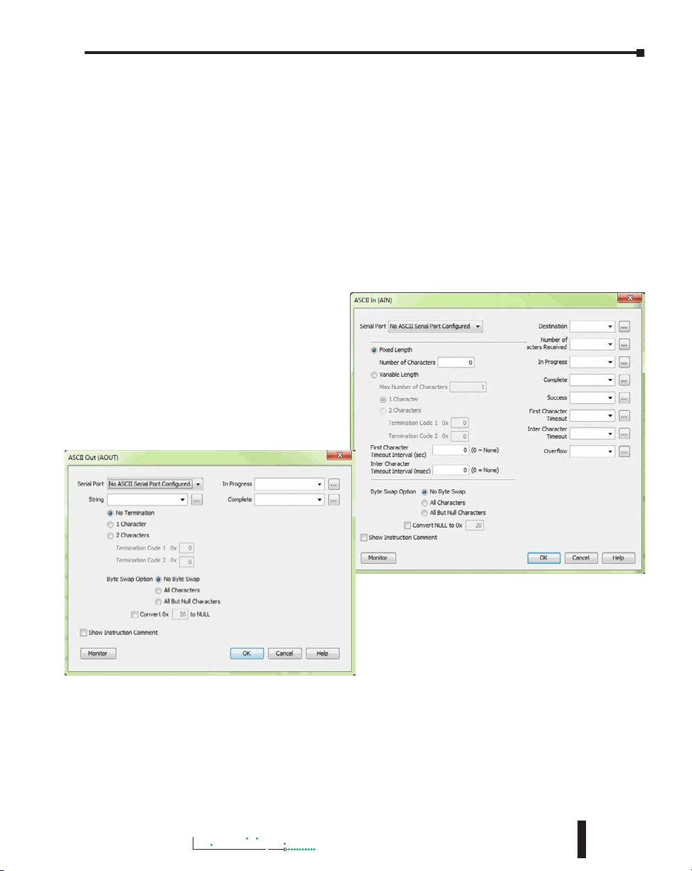
ASCII Instructions
The ASCII In/Out instructions use the String data type to send or receive text-based data
through the serial port. The String data type is only intended for use with the “printable
character set”. This can include numbers, letters or special characters.
With the ASCII In instruction,
the CPU can receive a fixed
length of characters or a variable
length of characters with a
termination code (an ‘end of
message’ character).
The ASCII Out instruction sends
text-based data out of the serial
port to various devices for control,
printing or display.
Hardware User Manual, 4th Edition, Rev. M
6-17
Page 18
Chapter 6: Communications
Productivity
Full duplex Mode (P3-550(E)/530)
1. RS232 can be set to FulDuplex node. Half Duplex is selected by default. This cna be changed in
the Hardware Configuration window for the CPU serial port.
2. AIN and AOUT instructions may be enabled at the same time.
3. AOUT may be enabled while AIN is already active, and vice versa.
4. The user may control treatment of buffered data before AIN is enabled using the checkbox
mentioned above.
5. RTS mode must be either always on or always off. Assert during transmit is not available.
Half duplex Mode [default] (P3-550(E)/530)
The ASCII instruction limitations are that it is not advisable to use the ASCII Out instruction to
send a String to a device that will respond (if the response is needed) and to use the ASCII IN (AIN)
instruction to try to receive this data.
1. AIN and AOUT cannot be enabled at the same time on the same serial port.
2. When the AOUT completes, the AIN cannot be enabled until the next logic scan.
3. The user may control treatment of buffered data before AIN is enabled using the checkbox
mentioned above.
Custom Protocol Instructions
The Custom Protocol is a HEX based protocol used to communicate with devices that do
not have the standard Modbus RTU Protocol. There are two instructions used with Custom
Protocol communication:
• Custom Protocol Out (CPO)
• Custom Protocol In (CPI)
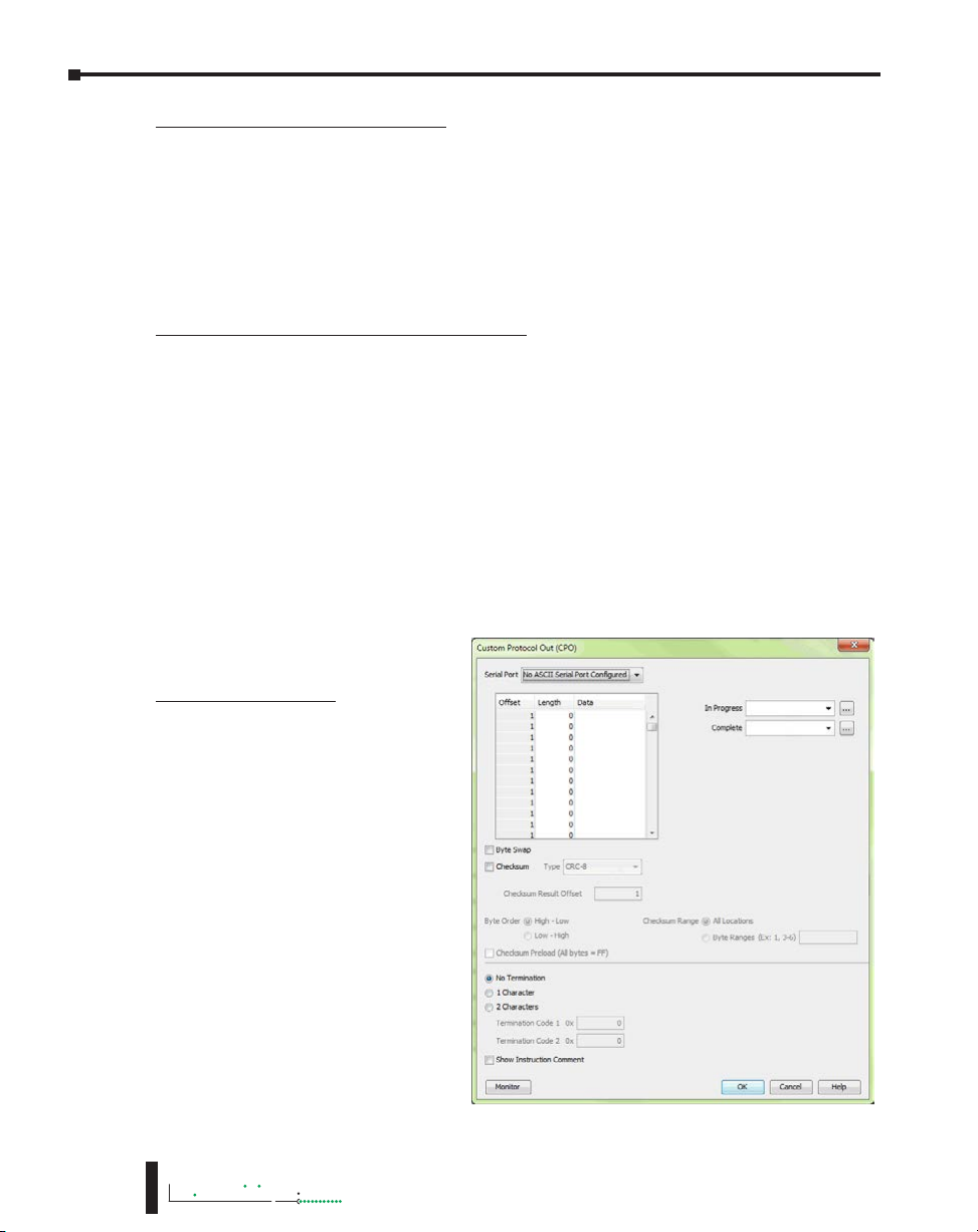
Custom Protocol Out
The Custom Protocol Out instruction
allows the user to send a ‘byte
formatted’ packet of data out of the
CPU serial port.
Constant values and/or Tag values
can be used as the source for data
transmitted. There are several
formatting options including Byte
Swap and Checksum.
6-18
3000
Hardware User Manual, 4th Edition, Rev. M
Page 19

Chapter 6: Communications
Productivity
3000
The Checksum option allows the user to select where in the packet the checksum should be
inserted, what type of Checksum (CRC-8 bit, CRC-16 bit, CRC-32 bit, XOR-8 bit, XOR-16
bit and XOR 32 bit), which bytes of the data source should be used in the calculation of the
checksum, what the byte order should be of the checksum (if greater than 8 bit) and how to
preload the checksum calculation.
If the device requires a different Checksum calculation, this can be done outside of the
instruction in other ladder code and the resulting Tag values can be inserted where appropriate
in the packet.
Termination characters can also be specified when needed.
The Custom Protocol Out instruction is for transmission only. If information needs to be
received from field devices, the Custom Protocol In instruction will have to be used. Unlike
ASCII, the Custom Protocol will buffer the received data. When the Custom Protocol In
instruction is executed, it will retrieve any data held in this buffer. Therefore, the lost responses
found with ASCII communication do not occur with Custom Protocol communication.
Custom Protocol In
The Custom Protocol In instruction
has similar formatting options to the
Custom Protocol Out instruction.
The Custom Protocol In instruction
will calculate the Checksum of the data
packet received based on the criteria
specified in the instruction and this
will determine the state of the status
bits assigned to the instruction. If the
Checksum calculation passes based on
the criteria specified in the instruction,
the “Success” status bit will become
true. If the Checksum calculation
fails, the “Checksum Error” status bit
will become true.
With the CPI instruction, the packet
termination must be specified, either
in terms of a termination character(s)
or a packet length. If a Checksum
is expected in the reply, be sure to
include this in the Fixed Length value
specified.
Hardware User Manual, 4th Edition, Rev. M
6-19
Page 20

Chapter 6: Communications
Productivity
Communications: Ethernet
TCP and UDP Port Numbers
When doing TCP/IP and UDP/IP communications, there is a Source Port number
and Destination Port number for every message. The Client device must be aware of the
Destination Port Number(s) that the Server device is expecting to see and the Server device
must listen for this Destination Port number. After the Server device has received the message
with the Destination Port Number that it is listening on, it will formulate the return message
(if the applications require this) with the Source Port Number from the message sent as its
Destination Port Number.
It is important to understand a little about the Port numbering concept because many Ethernet
devices, such as routers with firewalls, will block messages with Destination Port numbers
that are not configured for that device. Listed below are the default Port Numbers used in
the Productivity3000
going through routers in many applications.
Programming Software CPU Discovery
Programming Software Connection and Project Transfer
Modbus Client Connections
(MRX, MWX, RX and WX instructions)
Modbus Server Connections
GS-Drive Discovery
GS-Drive Connection
Remote I/O Discovery
Remote I/O Connection
Email Instruction
Ethernet IP
Ethernet IP
* Adapters may choose to respond using another port number.
®
system. Some of these are configurable, allowing more flexibility when
Port
Port Number
(Decimal Format)
8888 UDP No
9999 UDP No
502 TCP Yes
502 TCP Yes
28784 UDP No
502 TCP No
8887 UDP No
8877 UDP No
25 TCP No
44818 TCP Yes
2222 UDP No*
TCP or UDP Configurable
6-20
IP Addressing and Subnetting
IP Addresses (used in conjunction with the Subnet Mask and Default Gateway address) are
used for network routing. This allows for easy and logical separation of networks.
It is outside of the scope of this help file to explain how IP Addresses and Subnet masks are
configured for actual usage. There are many books, documents and tools (Subnet calculators)
on the internet that provide this information. Each facility and network will incorporate their
own rules and guidelines for how their networks are to be configured.
3000
Hardware User Manual, 4th Edition, Rev. M
Page 21
Chapter 6: Communications
Productivity
3000
PC Setup
For testing and verification purpose, it is
recommended that the PC and the CPU be on
an isolated Ethernet switch. Configure the PC’s
network interface card setting as described below.
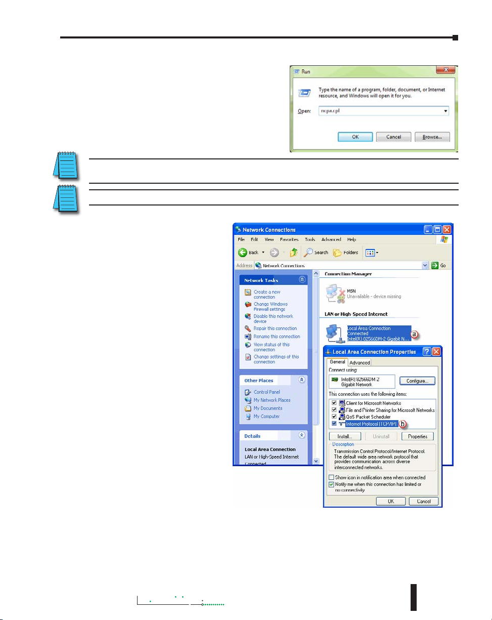
1. Go to Start, then Run, type ncpa.cpl in the
Open field and click on OK to bring up the
Network Connections dialog.
NOTE: Many system settings on your computer require Administrative privileges. Consult with your IT
department for necessary privileges and approvals.
NOTE: You should record initial settings prior to making any network configuration changes.
2. Network Connections
a. Right click on the
Network interface
shown in the Network
Connections dialog
and select Properties.
If there is more than
one Network Interface
on the PC, be sure
to choose the one
connected to the
Ethernet Switch with
the CPU on it.
b. From the Local Area
Connection Properties
window, highlight the
Internet Protocol(TCP/
IP) selection and click
on Properties.
Hardware User Manual, 4th Edition, Rev. M
6-21
Page 22
Chapter 6: Communications
Productivity
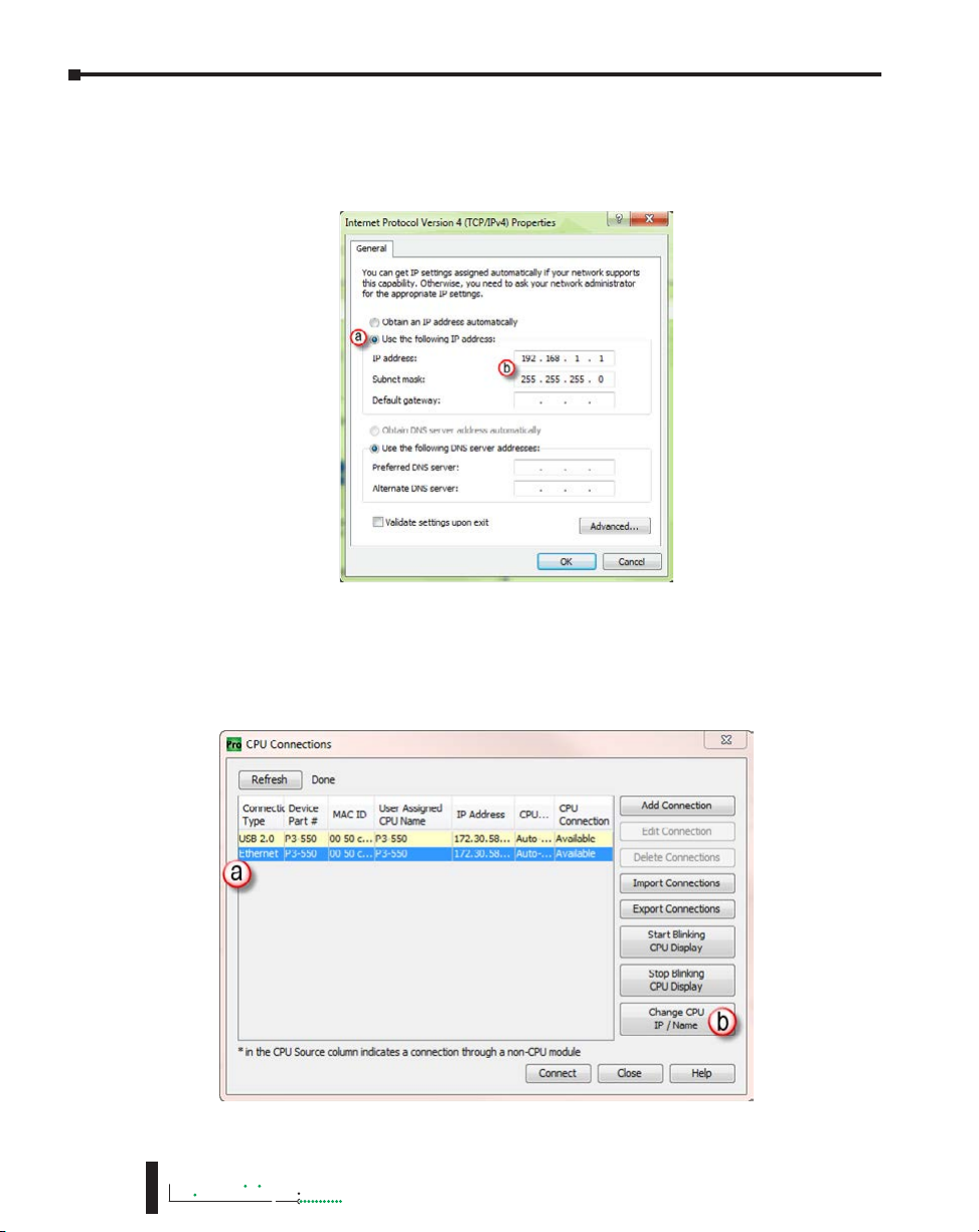
3. Internet Protocol (TCP/IP) Properties.
a. In the Properties window, select Use the following IP address.
b. Enter an IP Address of 192.168.1.1 and Subnet Mask 255.255.255.0 and select OK.
Select OK again on the Local Area Connection Properties window.
CPU Setup
Now configure the CPU’s network IP setting as shown below.
1. Select CPU from the Productivity3000® software Main Menu and then select Choose CPU
from the drop down menu.
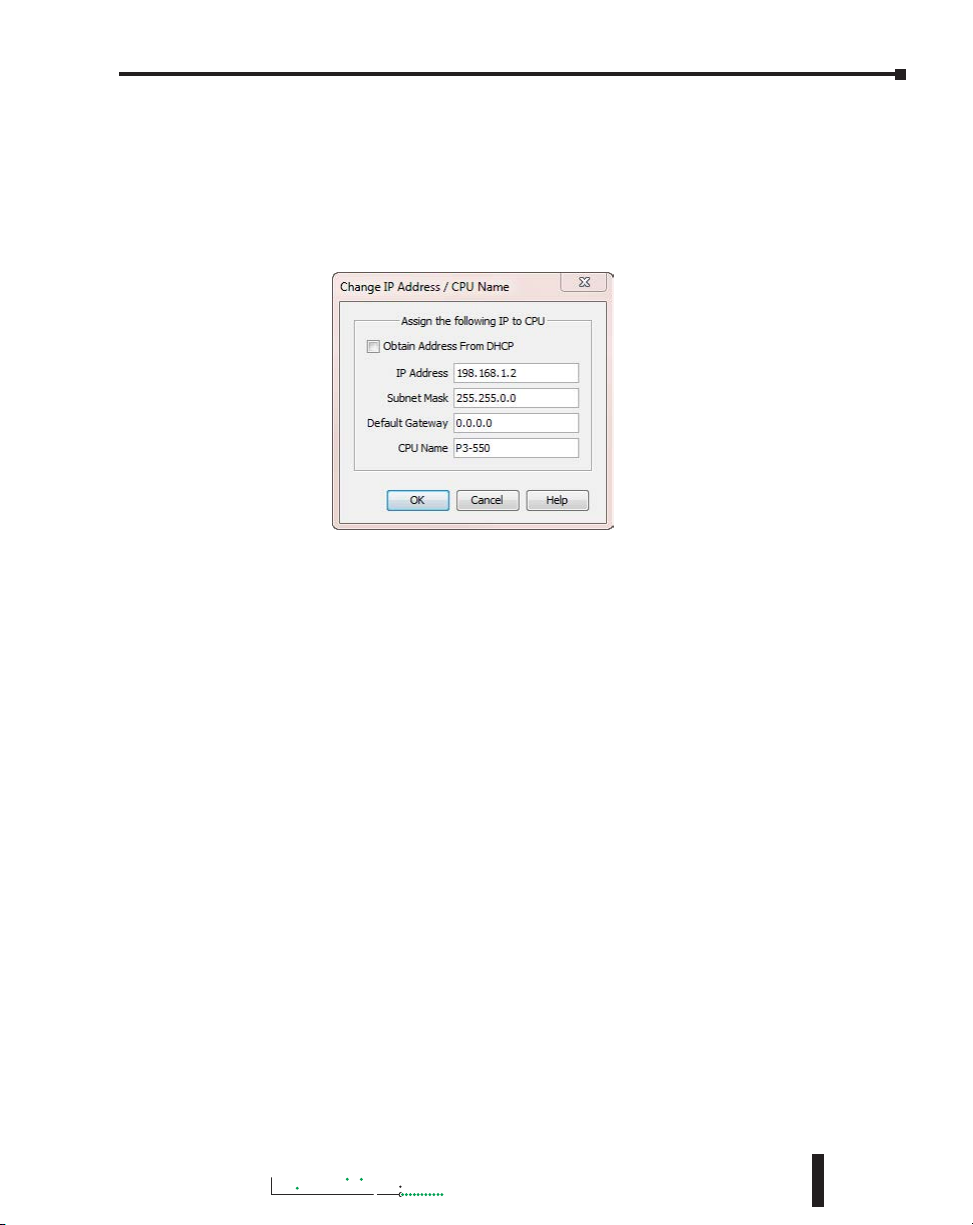
2. The CPU Connections window will open as shown below.
6-22
3000
Hardware User Manual, 4th Edition, Rev. M
Page 23
Chapter 6: Communications
Productivity
3000
a. Click to highlight the CPU connected to the Ethernet switch.
b. Select the “Change CPU IP/Name” button.
3. The Change IP Address/CPU Name window will open as shown below.
a. Enter an IP Address of 192.168.1.2 and Subnet Mask 255.255.0.0 for the CPU’s network
IP setting and select OK.
The CPU is now configured with the correct IP Address for connectivity with the PC. The IP
Address and Subnet Mask settings will very likely differ from what will be used in the actual
application. Consult the Network Administrator of the facility where the CPU will be installed
to get the appropriate settings for that network.
TCP Connection Behavior with Modbus TCP and Network Instructions
When performing communications over TCP, a Connection must be established before the
applications can transfer data. The connection is typically maintained until the application
decides that the connection is no longer needed and then the connection will be severed.
Frequent connects and disconnects are not efficient for the Client or the Server and can add
unnecessary network traffic. But maintaining connections needlessly is also costly to the Client
and Server in terms of processing and memory so this should also be avoided.
The CPU allows user control of Client connections through enabling and disabling the rungs
containing Modbus and Network instructions. The MRX, MWX, RX and WX instructions
have two options for sending messages: Automatic Poll and Manual Poll.
Automatic Poll sends out messages at a specified rate. Enabling the instruction performs a TCP
connect with the Server device. Once the connection is established, the instruction messages
are sent at the rate entered in the poll rate field. This continues until the instruction is disabled.
The TCP connection will automatically be severed five seconds after the instruction is disabled.
Manual Poll sends out a message each time the instruction is enabled. Enabling the instruction
performs a TCP connect with the Server device and sends the message one time. The TCP
connection will automatically be severed five seconds after receiving the reply from the Server
device. If the instruction gets another positive edge enable within the five seconds, the message
will be sent and the disconnect of the TCP connection will be delayed by an additional five
seconds.
Hardware User Manual, 4th Edition, Rev. M
6-23
Page 24

Chapter 6: Communications
Productivity
Communications Modbus Functionality
Master/Client Function Code and Data Type Support
The following table lists the Modbus data type, the function code and the CPU source data
type that is supported when the CPU is the Client or Master on a Modbus TCP or serial
connection.
Modbus Client/Master Support (Using MRX and MWX Instructions)
Function
Function Name
Code
01 Read Coil Status 000000 - 065535 000001 - 065536
02 Read Coil Status 100000 - 165535 100001 - 165536
Read Holding
03
04
05 Write Single Coil 000000 - 065535 000001 - 065536
Registers
Read Input
Registers
Modbus 984 Addressing
(Zero Based)
400000 - 465535 400001 - 465536
300000 - 365535 300001 -365536
Modbus 984
Addressing
Productivity3000® Tag Types
(Data designation or source)
Discrete Output (DO)
Boolean (C )
Boolean System (SBRW)
Discrete Input (DI)
Boolean (C )
Boolean System (SBRW)
Integer 8 bit Unsigned (U8)
Integer 16 bit (S16)
Integer 16 bit Unsigned (U16)
Integer 16 bit BCD (B16)
Integer 32 bit (S32)
Integer 32 bit BCD (B32)
Integer 32 bit Float (F32)
Integer 16 bit System (SWRW)
Integer 8 bit Unsigned (U8)
Integer 16 bit (S16)
Integer 16 bit Unsigned (U16)
Integer 16 bit BCD (B16)
Integer 32 bit (S32)
Integer 32 bit BCD (B32)
Integer 32 bit Float (F32)
Integer 16 bit System (SWRW)
Discrete Input (DI)
Discrete Output (DO)
Boolean (C )
Boolean System (SBRW)
Boolean System Read Only (SBR)
6-24
3000
Hardware User Manual, 4th Edition, Rev. M
Page 25

Chapter 6: Communications
Productivity
3000
Modbus Client/Master Support (Using MRX and MWX Instructions) (continued)
Function
Code
06
15
16
Function Name
Write Single
Register
Write Multiple
Coils
Write Multiple
Registers
Modbus 984 Addressing
(Zero Based)
Modbus 984
Addressing
400000 - 465535 400001 - 465536
000000 - 065535 000001 - 065536
400000 - 465535 400001 - 465536
Productivity3000
(Data designation or source)
Integer 8 bit Unsigned (U8)
Integer 16 bit (S16)
Integer 16 bit Unsigned (U16)
Integer 16 bit BCD (B16)
Integer 32 bit (S32)
Integer 32 bit BCD (B32)
Integer 32 bit Float (F32)
Integer 16 bit System (SWRW)
Integer 16 bit System Read Only (SWR)
Discrete Input (DI)
Discrete Output (DO)
Boolean (C )
Boolean System (SBRW)
Boolean System Read Only (SBR)
Integer 8 bit Unsigned (U8)
Integer 16 bit (S16)
Integer 16 bit Unsigned (U16)
Integer 16 bit BCD (B16)
Integer 32 bit (S32)
Integer 32 bit BCD (B32)
Integer 32 bit Float (F32)
Integer 16 bit System (SWRW)
Integer 16 bit System Read Only (SWR)
®
Tag Types
Hardware User Manual, 4th Edition, Rev. M
6-25
Page 26

Chapter 6: Communications
Productivity
Slave/Server Function Code and Data Type Support
The following table lists the Modbus data type, the function code and the CPU source data type
that is supported when the CPU is the Server or Slave on a Modbus TCP or serial connection.
Modbus Server/Slave Support
Function Code Function Name Modbus 984 Addressing
01 Read Coil Status 000001 - 065536
02 Read Coil Status 100001 - 165536
03 Read Holding Registers 400001 - 465536
04 Read Input Registers 300001 -365536
05 Write Single Coil 000001 - 065536
06 Write Single Register 400001 - 465536
15 Write Multiple Coils 000001 - 065536
Productivity3000® Tag Types
(Data designation or source)
Discrete Output (DO)
Boolean (C )
Boolean System (SBRW)
Discrete Input (DI)
Boolean System Read Only (SBR)
Integer 8 bit Unsigned (U8)
Integer 16 bit (S16)
Integer 16 bit Unsigned (U16)
Integer 16 bit BCD (B16)
Integer 32 bit (S32)
Integer 32 bit BCD (B32)
Integer 32 bit Float (F32)
Integer 16 bit System (SWRW)
String
Analog Input, Integer 32 bit (AIS32)
Analog Input, Float 32 bit (AIF32)
Integer 16 bit System Read Only (SWR)
Discrete Output (DO)
Boolean (C)
Boolean System (SBRW)
Integer 8 bit Unsigned (U8)
Integer 16 bit (S16)
Integer 16 bit Unsigned (U16)
Integer 16 bit BCD (B16)
Integer 32 bit (S32)
Integer 32 bit BCD (B32)
Integer 32 bit Float (F32)
Integer 16 bit System (SWRW)
Integer 16 bit System Read Only (SBR)
String
Discrete Output (DO)
Boolean (C )
Boolean System (SBRW)
6-26
3000
Hardware User Manual, 4th Edition, Rev. M
Page 27
Chapter 6: Communications
Productivity
3000
Modbus Server/Slave Support (continued)
Function Code Function Name Modbus 984 Addressing
16 Write Multiple Registers 400001 - 465536
Productivity3000
(Data designation or source)
Integer 8 bit Unsigned (U8)
Integer 16 bit (S16)
Integer 16 bit Unsigned (U16)
Integer 16 bit BCD (B16)
Integer 32 bit (S32)
Integer 32 bit BCD (B32)
Integer 32 bit Float (F32)
Integer 16 bit System (SWRW)
Integer 16 bit System Read Only (SBR)
String
®
Tag Types
Assigning Modbus Addresses to Tags
There are many different data types in the CPU. Because of this, the Modbus addresses need
to be mapped to the various tag data types in the CPU.
There are two ways to map Modbus addresses to Tags in the Programming software:
• Modbus mapping in Tag Database window.
• Modbus mapping when creating Tags.
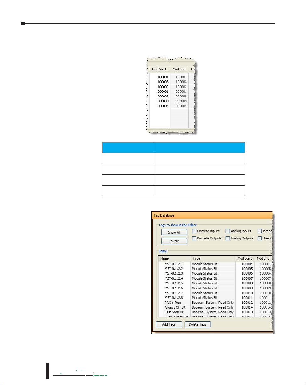
1. Modbus mapping in Tag Database window:
There are only two data sizes in the Modbus protocol: bits and words. In the CPU, there
are multiple size types, so it is sometimes necessary to map multiple Modbus addresses
to a single Tag entity. There are also array data structures in the CPU. When Modbus
addresses are mapped to arrays, they will be mapped as a contiguous block of addresses.
This is, in fact, the most efficient method to handle Modbus communications.
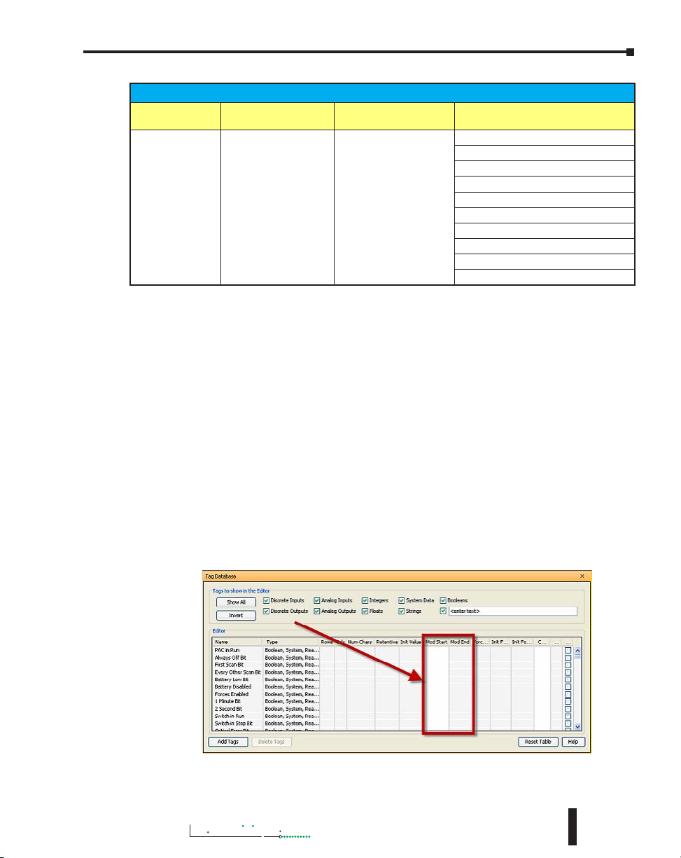
In the Tag Database window, there are two columns named “Mod Start” and “Mod
End”. To map a Modbus address to a tag in the Tag Database window, simply doubleclick in the Mod Start field for the Tag.
Hardware User Manual, 4th Edition, Rev. M
6-27
Page 28
Chapter 6: Communications
Productivity
When you do this, you will see two values appear in the field. The left most value is
the Modbus data type. This is fixed based upon the tag data type. The chart below
indicates the four different Modbus data types in the 984 addressing scheme.
Address Identifier Modbus 984 Address Type
0xxxxx
1xxxxx
3xxxxx
4xxxxx
Coil (Read/Write bit)
Input (Read Only bit)
Input Register (Read Only 16 bit word)
Holding Register (Read/Write 16 bit word)
6-28
The right most value that you
see in the “Mod Start” field
is the address offset (range is
from 1 – 65535). You can
accept the value that is prefilled for you or the value can
be changed. The software
automatically pre-fills the
address offset with the next
available address.
3000
Hardware User Manual, 4th Edition, Rev. M
Page 29
Chapter 6: Communications
Productivity
3000
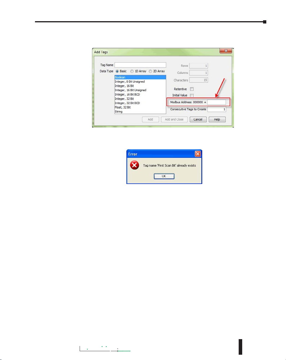
2. Modbus mapping when creating Tags:
Modbus addresses can be assigned to Tags as they are created in the Tag Database.
Type in the Modbus offset value when entering the Tag Name and Data Type. If the
address is already assigned, a warning message will appear.
Hardware User Manual, 4th Edition, Rev. M
6-29
Page 30
Chapter 6: Communications
Productivity
Modbus Options
The Modbus protocol does not have a specific method outlined for data types outside of bits
and 16-bit words. Most systems now have 32-bit data types. In order to transport 32-bit data
types across Modbus, they must be placed into two Modbus 16-bit registers. Unfortunately,
some devices do not support this and there are sometimes incompatibilities in the order of the
16-bit high word and low word handling between the devices.
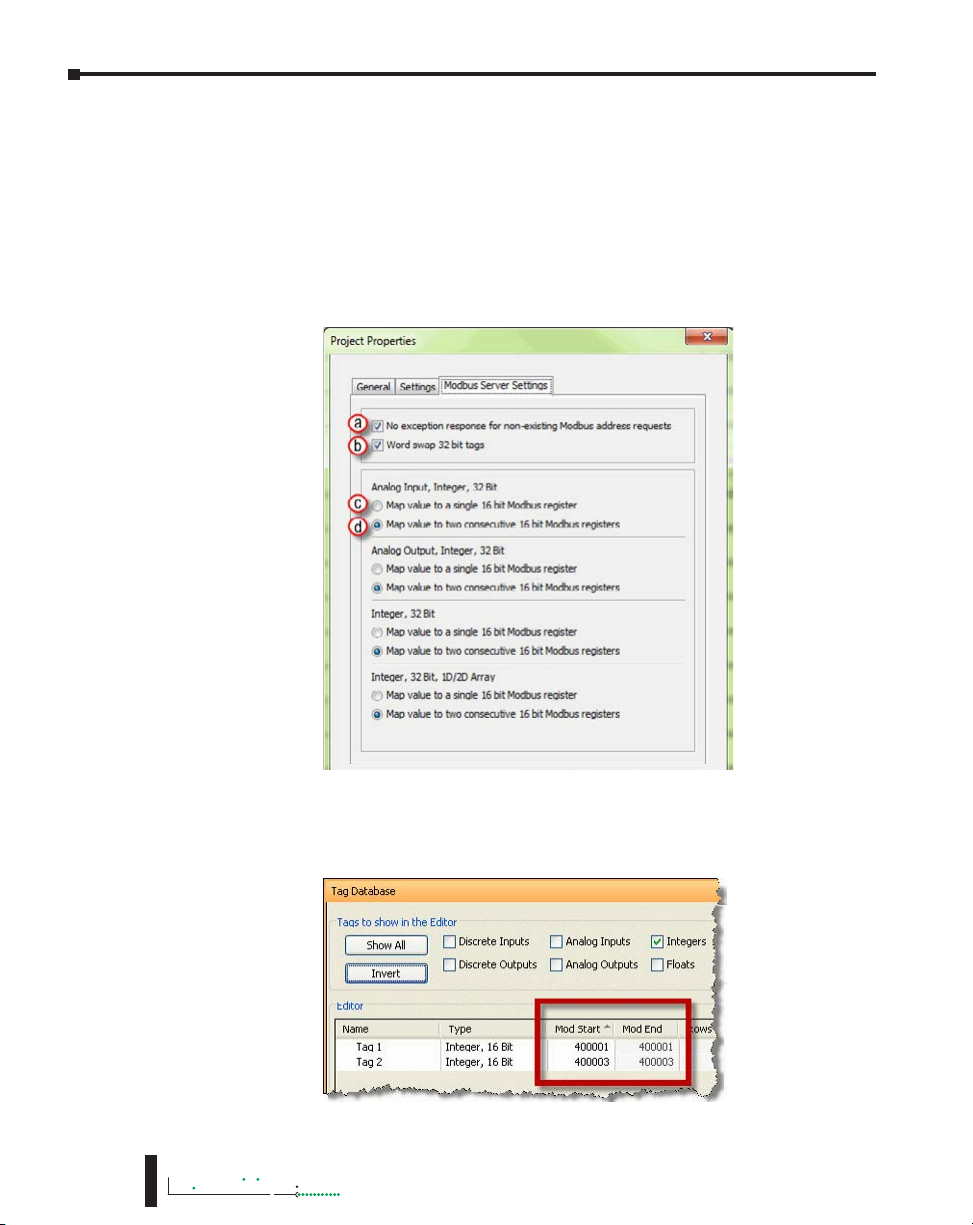
In order to help alleviate this situation, there are some options for handling this in the
programming software. To find the Modbus Address options, go to File and click on Project
Properties and then click on the “Modbus Server Settings” tab.
6-30
a. No exception response for non-existing Modbus address requests: Because the Modbus addresses
can be manually assigned to tags, it is possible that gaps can occur in the Modbus address
mapping. For example: Tag1 has Modbus address 400001 assigned to it and Tag 2 has Modbus
address 400003 assigned to it.
3000
Hardware User Manual, 4th Edition, Rev. M
Page 31

Chapter 6: Communications
Productivity
3000
Most Modbus Master/Client devices will attempt to optimize their data requests to a Modbus
Slave/Server device by requesting blocks of data instead of individual registers. In the case
mentioned previously, most Modbus masters would send one read request starting at 400001
and a size of three instead of sending two read requests starting at 400001 with size one and
400003 with size one as shown below.
In the example shown above on left, a Modbus Slave/Server device should give an exception
response since there is no Modbus Address of 400002 in the device. This method can cause a
lot of inefficiencies. By selecting the “No exception response for non-existing Modbus address
requests” option, the CPU will not give an exception response to the request. Note that if
Modbus address 400002 by itself were requested it would give an exception response.
b. Word swap option (S-32, AIS-32, AOS-32, F-32, FI-32, FO-32):
Word swap allows the word order of 32-bit tags to be changed when sending the values across
Modbus. The default selection is on, which returns the data low word first.
Tag1 (Integer, 32-Bit) = 305,419,896 (hex = 0x12345678)
Tag1 Modbus address = 400001, 400002
Modbus reply for Tag1 (Word Swap ON ) = 01 03 04 56 78 12 34
Modbus reply for Tag1 (Word Swap OFF) = 01 03 04 12 34 56 78
Hardware User Manual, 4th Edition, Rev. M
Low
Word
First
High
Word
First
High
Word
Last
Low
Word
Last
6-31
Page 32

Chapter 6: Communications
Productivity
c. Map value to a single 16 bit Modbus register:
This option allows for compatibility with devices that do not support 32-bit Modbus
functionality. This option can be selected individually for the Analog Input and Output Signed
32 data types and the Internal Signed 32 data types, including the array form of these data types.
This function is only useful when the value contained in a 32-bit tag does not exceed a signed
15-bit value (32,765).
Tag1 (Integer, 32-Bit) = 22136 (hex = 0x00005678)
With “Map value to a single 16 bit Modbus register” turned OFF =
Tag1 Modbus address = 400001, 400002
Modbus reply for Tag1 (Word Swap ON) = 01 03 04 56 78 00 00
With “Map value to a single 16 bit Modbus register” turned ON =
Tag 1 Modbus address = 400001
Modbus reply for Tag1 = 01 03 02 56 78
d. Map value to two consecutive 16-bit Modbus registers: Allows for 32-bit data types to be
mapped to two consecutive 16-bit registers. This option is selected as default.
All of the options in the “Modbus Address” tab of the Project Properties only apply to the
Modbus Slave/Server functionality. Similar options are available for the Modbus Master/Client
functions as well and are available in the MRX and MWX Modbus instructions.
6-32
3000
Hardware User Manual, 4th Edition, Rev. M
Page 33

Chapter 6: Communications
Productivity
3000
Modbus Instructions
To read or set data in other Modbus Slave/Server devices, there are two instructions available
in the programming software, Modbus Read and Modbus Write.
• The Modbus Read (MRX) instruction is used to read data from other Modbus devices into
Tags of the CPU.
• The MRX instruction can be used for Modbus TCP or Modbus RTU. There are several
status bits that can be used to determine whether the read message was successful and if it
was not, the reason why.
Hardware User Manual, 4th Edition, Rev. M
6-33
Page 34

Chapter 6: Communications
Productivity
There is an “Automatic Polling” feature in the instruction to make it easier to read a device on a
pre-determined poll rate. There is also a “poll offset” field that can be used when simultaneous
instructions are enabled with the Automatic Polling feature to help stagger the flow of messages
being sent to the network.
• The Modbus Write (MWX) instruction is very similar in layout and configuration to the
MRX instruction. It is used to write values to a Modbus device from the tags in the CPU.
6-34
• The MWX operates very similarly to the MRX instruction. There are also many status bits
to indicate the success or reason of failure when sending a message.
• The Automatic Polling option is also available to the MWX instruction, although greater
care should be taken when using this feature in this instruction. This is explained in better
detail in the “Message Queue” section.
3000
Hardware User Manual, 4th Edition, Rev. M
Page 35

Chapter 6: Communications
Productivity
3000
Network Instructions
The Network Read (RX) and Network Write (WX) instructions are used to communicate to
other CPUs. They are very similar in operation to the MRX and MWX instructions but they
target Tag Names instead of Modbus addresses in the other CPU. There is also a significant
performance gain in using the RX and WX instructions when communicating to other CPUs
as opposed to using the MRX and MWX instructions.
The same status bits are available in the RX instruction as in the MRX instruction and operate
in the same manner. The greatest difference in the RX versus the MRX is that with the RX,
the Tag Name in the target CPU can be referenced directly and does not need a corresponding
Modbus address. The way this is accomplished is by mapping local and remote tag names
together within the local CPU’s RX instruction. Once the instruction is set up to read a remote
project, the “Tags of Remote Project” or “Array Tags of Remote Project” drop down lists will
be accessible. Map the Tag of the Remote project to a Tag in the Local project to read this
data.
Hardware User Manual, 4th Edition, Rev. M
6-35
Page 36

Chapter 6: Communications
Productivity
6-36
The WX instruction operates in the same manner except that the data from the Local tags will
be written into the Tags of the remote project. No Modbus mapping is required.
NOTE: The PC programming software project for the Remote CPU must be accessible by the PC running
the programming software for the Local project.
Automatic Poll versus Manual Polling and Interlocking
In many cases when performing multiple communications requests to other devices, the
message flow must be explicitly controlled in ladder code so that a message is not sent while
another one is in operation. This usually requires writing ‘interlocking’ code between the
instructions which typically involves the use of timers and shift registers, etc. Sometimes this
is necessary because of the application but in other cases where the CPU just wants to read
changing values from other devices and the frequency of that update is not critical it would be
much more efficient to skip the unnecessary code complexity of interlocking.
The desire to make it easier to communicate to other devices brought about the “Automatic
Polling” feature and the “Message Queue” in the CPU. The Automatic Polling feature allows
the user to choose the rate at which they desire to send messages without having to use a separate
timer and enable logic. The ‘Message Queue’ allows the user to stage the messages from the
ladder code to go out to each physical communications port without requiring interlocking logic.
3000
Hardware User Manual, 4th Edition, Rev. M
Page 37

Chapter 6: Communications
Productivity
3000
The implementation of how the message queue works is slightly different based on whether the
request is a read request or a write request.
Read Request Flowchart
Read or
Write?
Write
Read
Go to Write Request
Flowchart
Using
Automatic
Poll?
No
Request
Already in
Queue?
No
Add
Request to
Queue
Timer
Yes
Yes
Complete?
Yes
Discard
Request
No
Go to Next
Instruction
Write Request Flowchart
Read or
Write?
Write
Use
Automatic
Poll?
No
Add
Request to
Queue
Read
Yes
Go to Read Request
Flowchart
Timer
Complete?
Yes
No
Go to Next
Instruction
Write requests will fill the queue much faster than read requests. That’s why it is advisable to
carefully choose when doing write requests whether to use the “Automatic Poll” feature or to
manually send write requests only when needed (data to write has changed). When designing
a system, it is important to know the total time it takes to send a request and get a reply for
each target device. The Poll time should be longer than this time. The longer the poll time
can be, within tolerance of the application, the better the overall network performance. So for
efficiency in programming and for the best possible performance for the system, conservative
poll rates should be used when utilizing the “Automatic Poll” feature.
There is also a “Poll offset” field in the communications instructions. This helps prevent the
instructions from being queued all at the same time. When the CPU project starts, there is a
master timer that begins. The ladder scan will look to see if the instruction is enabled. If it is
enabled, it will begin the Automatic Poll timer at the specified poll offset value from the master
time clock.
Hardware User Manual, 4th Edition, Rev. M
6-37
Page 38

Chapter 6: Communications
Productivity
Message Queue
If the application requires more explicit, orderly control of each message sent to the devices,
turn off the “Automatic Poll” feature. Using the instruction’s status bits, logically control each
message as required.
All of the above explains how messages get into the “queue”. There are several factors involved
with how each queue (1 for each physical port) is emptied.
• Serial port queues: The serial port queues empty slower than the Ethernet port
queues, not just because of the hardware speed itself but because of the nature of serial
communications. Each request sent must wait for a response or a timeout (whichever
comes first). Once the reply is received for a request or a timeout has occurred, the next
item in the list can be sent. So the response time of the slave devices on the network will
largely affect the speed at which the queue fills and empties.
• Ethernet port queues: The Ethernet port queue can empty faster because when sending
requests to multiple devices, the CPU does not have to wait on a response from one device
before sending a request to another device due to the inherent nature of the Ethernet
hardware. However, sending multiple requests to the same Ethernet device does necessitate
that the CPU waits for a response from the first request before sending another request to
that same device.
Another difference in the Ethernet port queue versus the Serial port queue spawns from the
TCP ‘connection’ based behavior of Modbus TCP. If a TCP connection is lost to a device
and there are still requests in the queue for that device, those requests will be dropped from the
queue. There are three ways this can happen:
1. If a TCP timeout occurs (server device fails to respond within specified timeout value), the TCP
connection is lost.
2. If the server device closes the connection, then all of the requests will be dropped.
3. And, finally, if all rungs with communications instructions to a device are disabled for five
seconds, the CPU will drop the TCP connection for that device in order to free up valuable
resources that could be used elsewhere in the system.
This is another factor that should be considered when designing the system. If it is imperative
that no message be lost when communicating to a device, each instruction should be explicitly
handled one by one (interlocking logic).
6-38
3000
Hardware User Manual, 4th Edition, Rev. M
Page 39

Productivity
3000
EtherNet/IP for the Productivity Series
Terminology Definitions
A lot of terminology associated with EtherNet/IP is not always clear. Some of these terms are
listed below along with their respective definitions.
• Scanner: This is the term used to describe the device that initiates the EtherNet/IP sessions.
The Scanner is sometimes referred to as the “Originator” as well. In more standard Ethernet
terms, the Scanner would often be called the “Client”.
• Adapter: This is the device that responds to the EtherNet/IP communications that are initiated
by the Scanner. The Adapter is also known as the “Target” as well. Typically, the Adapter is an
Ethernet “Server”.
• Object: In EtherNet/IP, an Object is a representation of a defined set of Ethernet connections,
behaviors, services and data attributes. There are standard objects and there are custom defined
objects as well. See Object Modeling example below.
• Class: A Class is a set of Objects that are related in some fashion. See Object Modeling example
below.
• Instance: An Instance is an actual, usable manifestation of an Object. See Object Modeling
example below.
• Attributes: Attributes are the specific items within an Object Class. The category of Attributes
should be the same for all Instances of an Object but the actual Attribute itself might vary. See
Object Modeling example below.
• Connection Point: A Connection Point value is the “Class Code” reference for a data block.
This value is required for access to input and output data in IO Messaging. It is typically
defined for each input and output data block by the Adapter device manufacturer.
• IO Messaging: IO Messaging (also called “Implicit Messaging”) is a method of reading and
writing blocks of data without defining the Connection Point and size for each block transfer.
The Connection Point, size and transfer rate (RPI) are defined at the beginning and then the
data blocks are transferred at the specified intervals.
• Explicit Messaging: This method of reading or writing data requires that each message defines
the type of data and size of data needed for each request.
Chapter 6: Communications
Object Modeling Example:
Class ------- Definition of Automobile
Attributes -- Make, Model, etc…
Object ------ A Ford Mustang
Instance ----Sally’s Ford Mustang
Hardware User Manual, 4th Edition, Rev. M
6-39
Page 40

Chapter 6: Communications
Productivity
Network Layer Chart
The diagram above illustrates the OSI seven layer model and how EtherNet/IP fits into this
model. In general, there are three basic layers for sending and receiving data in the EtherNet/
IP protocol:
• EtherNet/IP layer (Register Session, etc…)
• CIP layer (CIP Forward Open, etc…)
• The uppermost layer,which contains several different types of messaging.
The ODVA specification defines many different types of messaging that reside on the CIP layer.
Two types of messaging supported in the phase 1 release of the Productivity3000® EtherNet/IP
protocol are IO Messaging and Explicit Messaging. IO Messaging is accomplished through a
Class 1 Connection and Explicit Messaging can be accomplished through a Class 3 Connection
or an Unconnected Message.
Tag Based Messaging (used for reading and writing values to Allen Bradley Control and
ComCPUtLogix PLCs) and PCCC (used for reading and writing values to Allen Bradley
MicroLogix and SLC PLCs) are planned for subsequent phases of this protocol.
6-40
EtherNet/IP Data
When doing IO Messaging, the data that is transported is defined as “Input” data and “Output”
data. Don’t confuse this type of data with what most PLCs define as Input data and Output
data. In most PLCs, Inputs are typically associated with an Input module that reads point from
real word devices. Outputs are typically associated with an Output module that turns off and
on real word devices.
In IO Messaging, Input data is data that is sent from the target device back to the Originator
or to multiple devices that are listening (multicast messages). Output data is data that is sent
from the Target device. This data may or may not be connected to real word devices. That
is completely dependent upon the Adapter device. For example: When the Productivity3000
is configured as an EtherNet/IP Adapter device, the Input data and Output data is defined in
internal data arrays and does not directly tie to any Input and Output point to the real world.
If it is desired to tie these array elements to real word devices, that must be accomplished in
code by Copy commands (or other instructions).
NOTE: The Scanner (originator) in the P3000 will only accept messages from an Adapter (target) device
that the Scanner has established a connection to.
NOTE: The Adapter (target) in the P3000 will respond back to a Scanner (originator) in the method
(Multicast or Unicast) that is sent in the forward open message from the Scanner (originator).
3000
Hardware User Manual, 4th Edition, Rev. M
Page 41
Chapter 6: Communications
Productivity
3000
Class 1 and Class 3 Connections
What are they and how are they best used?
• Class 1 Connection is the transport mechanism that IO Messaging uses to send data. The basic
concept is that data is sent in one direction: the Originator sends Output data in a Unicast UDP
message to the Target and the Target sends Input data in either a Unicast message back to the
Originator or Multicast UDP messages to multiple devices. The Input data and Output data
messages have no relationship to each other. This method works well for Remote I/O type data
and is very efficient due to little overhead and reduced handshaking messages on the wire. Class
3 Connection is one of the mechanisms that Explicit messaging uses. Class 3messaging uses
TCP messages unlike Class 1. Each Class 3 request has a header that defines the type of data
requested as well as the size requested. It allows for more flexibility in messaging but does create
additional overhead.
NOTE: Explicit messaging can be accomplished with unconnected messages as well for more infrequent
requests. Explicit messaging is a slower performing method of communications but it typically allows for
more flexibility and control when the situation requires it.
When can the P3000 CPU use Class 1 or Class 3 Connections?
• Class 1 and Class 3 Connections can be accomplished with the Productivity3000® CPU as an
Adapter or as a Scanner or both simultaneously.
How many connections can the P3000 support for Ethernet IP?
• 4 - TCP
• 4 - Ethernet IP
• 4 - CIP (Up to 4 CIP connections are allowed per Ethernet IP connection. Therefore, if one
device can support 4 CIP connections then you can have up to a total of 16 CIP connections
using 4 devices)
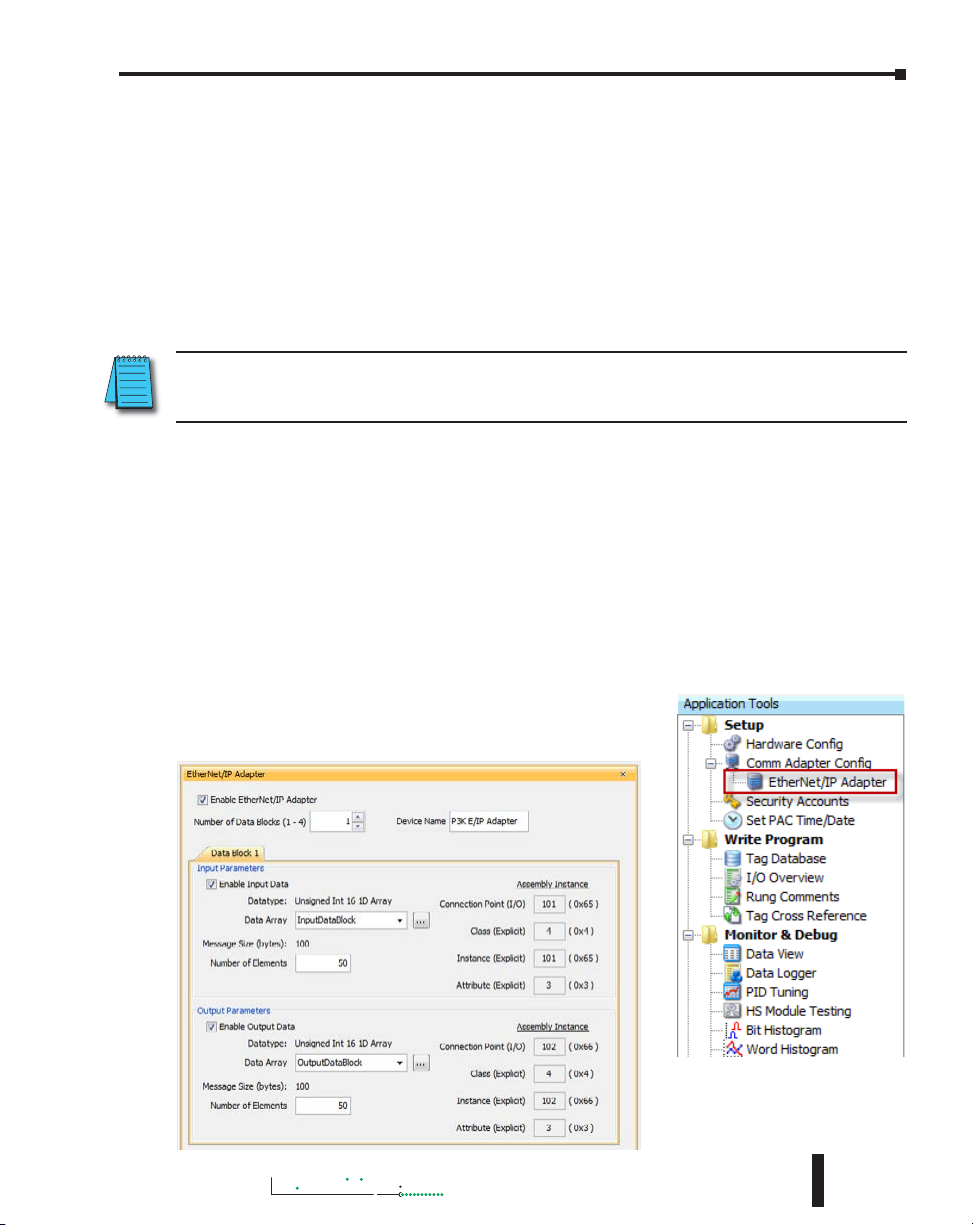
Example Setup: Productivity3000 as EtherNet/IP Adapter
The Adapter setup is accomplished through the EtherNet/IP
Adapter setup under the Comm Adapter Config section of the
Setup menu as seen on right.
Hardware User Manual, 4th Edition, Rev. M
When the EtherNet/IP Adapter
is selected from the menu the
window shown here will open.
6-41
Page 42

Chapter 6: Communications
Productivity
Fill in the required parameters and once configured these parameters will be used to configure
the Scanner side as shown in the examples below. The first example shows how to setup a
Class 1 IO Message connection from a 3rd party EtherNet/IP Scanner device (an Allen Bradley
PLC).
6-42
The following example shows how a Class 3 Explicit Message might be accomplished from a
3rd party device (Allen Bradley PLC). As you can see the Input Data must be retrieved in one
connection or message and the output data in another. Remember that Class 3 messaging is
not as efficient in protocol messaging as Class 1 but it does allow for granular control.
NOTE: In this example, size configuration is not shown on the Scanner side. The tag created for the
Destination must be large enough to contain the data requested (shown with dashed boxes).
3000
Hardware User Manual, 4th Edition, Rev. M
Page 43

Chapter 6: Communications
Productivity
3000
Hardware User Manual, 4th Edition, Rev. M
6-43
Page 44

Chapter 6: Communications
Productivity
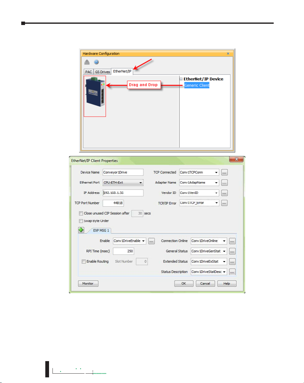
Example Setup: Productivity3000® as EtherNet/IP Scanner
This example shows how to connect the Productivity3000 Scanner function to an EtherNet/IP
adapter device using Class1 IO Messaging. First, create an EtherNet/IP device in the Hardware
Configuration as seen below:
Configure the parameters to match
the settings of the Adapter device.
The image on right shows the setup
of the Input data.
The size, in this case, is dynamic
to the configuration of the device.
For this particular example, we
configured the device in a manner
that allows it to publish 8 bytes
of data for Input. Many devices
will have a fixed configuration
that should be published in the
manufacturer’s documentation.
6-44
3000
Hardware User Manual, 4th Edition, Rev. M
Page 45

Productivity
3000
The Output data must also be
configured. Its data is also dynamic
based upon the configuration. In
our example, we configured the
device in a manner that caused it
to require 8 bytes of Output data.
Chapter 6: Communications
The image on left shows the setup for the
Configuration data. The Configuration data,
for most devices, is a fixed size. Some devices
will require that the Configuration data
Connection Point be included in the Forward
Open message (as shown on left) even if the
size is 0. Some devices will require that the
Configuration data Connection Point not be in
the Forward Open and the checkbox option in
the image below would need to be de-selected.
Hardware User Manual, 4th Edition, Rev. M
6-45
Page 46
Chapter 6: Communications
Productivity
The following example shows how to connect the Productivity3000® Scanner function to
an EtherNet/IP adapter device using Class 3 Explicit Messaging. As with IO Messaging, an
EtherNet/IP device must be created in the Hardware Configuration as seen below:
6-46
Explicit Messages can be performed in 2 ways: Unconnected or Connected (Class 3). The
advantage of using Unconnected messaging is it allows more discrete control of each request.
The disadvantage of Unconnected messaging is that Unconnected messages have a lower
priority and will take longer to get serviced on some devices. Connected messages get serviced
faster since there is a connection established to the device. If Connected messaging is desired,
create an Explicit Message tab as shown in the image above. If Unconnected messaging is
desired, do not create an Explicit Message tab. Only fill out the information in the upper
portion of the EtherNet/IP Client Properties window.
3000
Hardware User Manual, 4th Edition, Rev. M
Page 47

Chapter 6: Communications
Productivity
3000
Once the desired parameters have been entered, the device may now be referenced in the
Explicit Message Instruction. If Unconnected messaging has been selected, choose the
Unconnected MSG option in the Connection drop down box. If Connected messaging has
been selected, choose the Explicit Message that was configured in the EtherNet/IP Client
Properties window in the Connection drop down box. The rest of the settings should be
matched to the specifications documented by the manufacturer. An example for requesting
the Identity of a device is shown below. The data array configured for this function must be
sufficient in size to hold the returned data from the device for this object. Data can also be
written to the device if it supports an object for this purpose. If data is being written, enable the
Output selection and specify the data array and size required by that device’s object.
Troubleshooting Tips:
a. Use the diagnostic tags in the Hardware Configuration and Explicit Message Instruction:
As explained previously in the Network Layer Chart section, there are multiple layers
of messaging involved with EtherNet/IP. If it appears that the Productivity3000 is not
communicating with another EtherNet/IP device, there are diagnostic tags available to
narrow down which layer of the protocol is preventing successful communications.
Hardware User Manual, 4th Edition, Rev. M
6-47
Page 48

Chapter 6: Communications
Productivity
1. At the TCP layer, there is a TCP Connected field that will expose the status of the
2. There is an Adapter Name field for a String tag and a Vendor ID field for an Integer
3. At the CIP layer, there is a Connection Online field for a Boolean tag.
4. There are three additional fields to help determine why the CIP session might not
b. Use the TCP connected tag:
Step 1 is to check the TCP Connected tag. If the connection has been enabled (by turning
on the tag configured in the Enable field or triggering an Explicit Message instruction with
an Unconnected MSG specified) and the TCP Connected tag is not true, check the following
items:
• Cabling. Ensure that all of the cables are connected and in good shape. In most cases,
• IP address and correct subnet. Check that the IP address entered into the IP Address
• TCP Port number. The default listening TCP port number for EtherNet/IP is 44818.
TCP/IP connection when a tag is populated in this field.
tag. Both of these fields can help to identify whether the Productivity3000 is
connected to the correct device or not.
be successful: General Status for an Integer tag, Extended Status for an Integer Data
Array and Status Description for a String tag.
the Ethernet port that the cable is connected to should indicate a Link Good LED.
Ensure that any interim Ethernet switches are powered up and functioning and that the
end device is powered up and functional.
field is the correct address for the device that you are connecting to. Also check that
the EtherNet/IP device’s IP address and subnet mask is compatible with the IP address
and subnet mask of the Productivity3000. If there are any routers in between the two,
ensure that a proper default gateway that matches the router’s IP address is configured.
If you are unfamiliar with proper IP addressing and subnet configuration, consult with
the network administrator for guidance.
Check that the target device is listening on this specific port number. If it is not, change
the value in TCP Port Number field to the appropriate value. If there are interim router
devices that are using port forwarding, ensure that the router is properly configured for
this setup.
6-48
NOTE: Attempting to do IO Messaging across routers (different subnets) is unlikely to be successful. IO
Messaging uses multicast messaging in many cases and the Port number is not necessarily fixed when the
IO Messaging is established (the Forward Open message has the ability to ‘negotiate’ the port number used
for the IO Messages).
• Adapter Name and Vendor ID. If the network contains many EtherNet/IP devices
and these devices may not necessarily be connected to the Productivity3000, it may be
a good safeguard to check the Adapter Name and Vendor ID returned and verify that
these devices are the correct devices to connect to.
c. Use the Connection Online and Error tags:
If the TCP Connected tag is true and the Adapter Name and Vendor ID look correct, the next
tags to look at are the Connection Online, the General Status, the Extended Status and the
Status Description.
If the Enable tag is true and the Connection Online tag is not true, check the General Status
value along with the Extended Status value(s) and the Status Description. If the General Status
value and the Extended Status value(s) are part of the defined errors from the ODVA
3000
Hardware User Manual, 4th Edition, Rev. M
Page 49

Chapter 6: Communications
Productivity
3000
specification, the Status Description should also return a more descriptive String. Once these errors
are known, it may possible to very simply make the adjustment in the settings to correct the issue. If
it is not obvious from the description, first check the manufacturer’s documentation for corrective
action in this particular scenario.
If the manufacturer’s documentation doesn’t give corrective action, check the EtherNet/IP Error
Code List in this chapter for possible solutions.
NOTE: This may not always solve the problem as each device manufacturer may publish the error for
slightly different reasons.
If the Connection Online tag is true and the data being received is different than what is expected,
verify that the correct Connection Point values and/or Class, Instance, Attribute values are
configured. There may be multiple areas of available data in that device. Verify that the correct data
types are being used for both sides. If the data types are mismatched, this may make the data ‘appear’
to be incorrect.
Another great tool that can be used is Wireshark. Wireshark is a free network analyzer tool that can
be downloaded from www.wireshark.net .
NOTE: Using this tool implies some knowledge of how networking protocols function. Using Wireshark
will also require that you have a true Ethernet hub (not an unmanaged switch) or a managed switch with
Port mirroring capability.
You may also use the following basic steps to check your Ethernet IP Setup.
Ethernet IP I/O Message Troubleshooting:
1. Does the IP Address set up in the Scanner match the Adapter IP Address?
2. Is the enable tag entered into the Scanner turned ON?
3. Does the connection point entered into the I/O Message Data Block match the connection point
of the Adapter?
4. Does the number of elements match the Adapter?
5. Does the data type match the Adapter?
Steps 4 & 5 are important because the number of bytes being read from or written to the Adapter
have to match the Adapter bytes allocated.
Ethernet IP Explicit Message Troubleshooting:
1. Does the IP Address set up in the Scanner match the Adapter IP Address?
2. Is the enable tag entered into the Scanner turned ON when not using the Unconnected MSG
connection type?
3. Make sure the logic for the EtherNet/IP Explicit Message (EMSG) is TRUE so the instruction is
enabled.
4. When using Get or Set single attributes in the Service field make sure the Instance ID matches the
Instance ID of the Adapter.
5. When using Generic in the Service field make sure the Service ID, Class ID, Attribute ID and
Instance ID match the Adapter settings.
6. Does the number of elements match the Adapter?
7. Does the data type match the Adapter?
Steps 6 & 7 are important because the number of bytes being read from or written to the Adapter
have to match the Adapter bytes allocated.
Hardware User Manual, 4th Edition, Rev. M
6-49
Page 50

Chapter 6: Communications
Productivity
ProNET
Productivity Network (ProNET) provides the ability to share data with other P-Series CPU’s,
This can easily be accomplished using the Productivity Network (PNET) setup in the Hardware
Configuration window used to join a data sharing network consisting of other P-Series
controllers.
Each member of the data sharing network receives data from all of the other P-Series controllers
on that data sharing network. Each node can optionally send data to the other nodes of the data
sharing network by electing to “publish” data.
The ProNET configuration uses UDP broadcast packets to publish the blocks of data to the
network. One caveat with the use of broadcast packets is that it limits the scope of the shared
data network to the local broadcast domain.
ProNET uses the verbs ‘publishing’ and ‘subscribing’ to describe how the controller data is
exchanged with other P-Series controllers on the data sharing network.
Publishing is analogous to sending data, and is done only if ProNET is configured to ‘publish’
one or more of its assigned tags. If so configured, the P-Series controller will broadcast a packet
that contains the data from the selected tags.
Subscribing is analogous to receiving data, and is accomplished by ‘subscribing to’ a publisher’s
global ID of any P-Series CPU on the data sharing network set up to publish its data.
6-50
3000
Hardware User Manual, 4th Edition, Rev. M
Page 51

Chapter 6: Communications
Productivity
3000
The ProNET configuration works with a 1D array tag(s) that can contain up to 65535 elements,
however you are limited to 32 total 32-bit elements, 64 total 16-bit elements, or 128 total 8-bit
or Boolean elements of data per publisher array data type. These tags provide the local storage
for the data sent and received over the data-sharing network.
NOTE: The message size for each data type is limited to 128 bytes regardless of the defined array size.
Data Type
Boolean
Integer 8-Bit
Integer 16-Bit
Integer 32-Bit
Integer 64-Bit
Number of
Elements
128
128
64
32
32
When the input logic to the ProNET configuration is Enabled, it operates at a fixed rate of 10
times per second (100ms). The instruction will publish all of the elements of the array that it
is configured to publish, and will process any ProNET nodes that it receives. When the input
logic is OFF, (the device is disabled), it DOES NOT publish any of its tags and DOES NOT
process any ProNET nodes that it receives.
Custom Protocol over Ethernet Functionality
Besides Modbus RTU, EtherNet/IP, and ProNET the Productivity1000 system has the ability to
communicate via Ethernet with other devices using the Custom Protocol over Ethernet (CPoE).
Custom Protocol over Ethernet
The Custom Protocol is a HEX based protocol used to communicate with devices that do
not support one of the other protocols on Productivity1000. There are two steps to initiate
communications via the Custom Protocol over Ethernet:
First you must set up a device in the hardware configuration under the CPoE tab.
Then you must use the Custom Protocol Ethernet (CPE) instruction to initiate messages.
Hardware User Manual, 4th Edition, Rev. M
6-51
Page 52
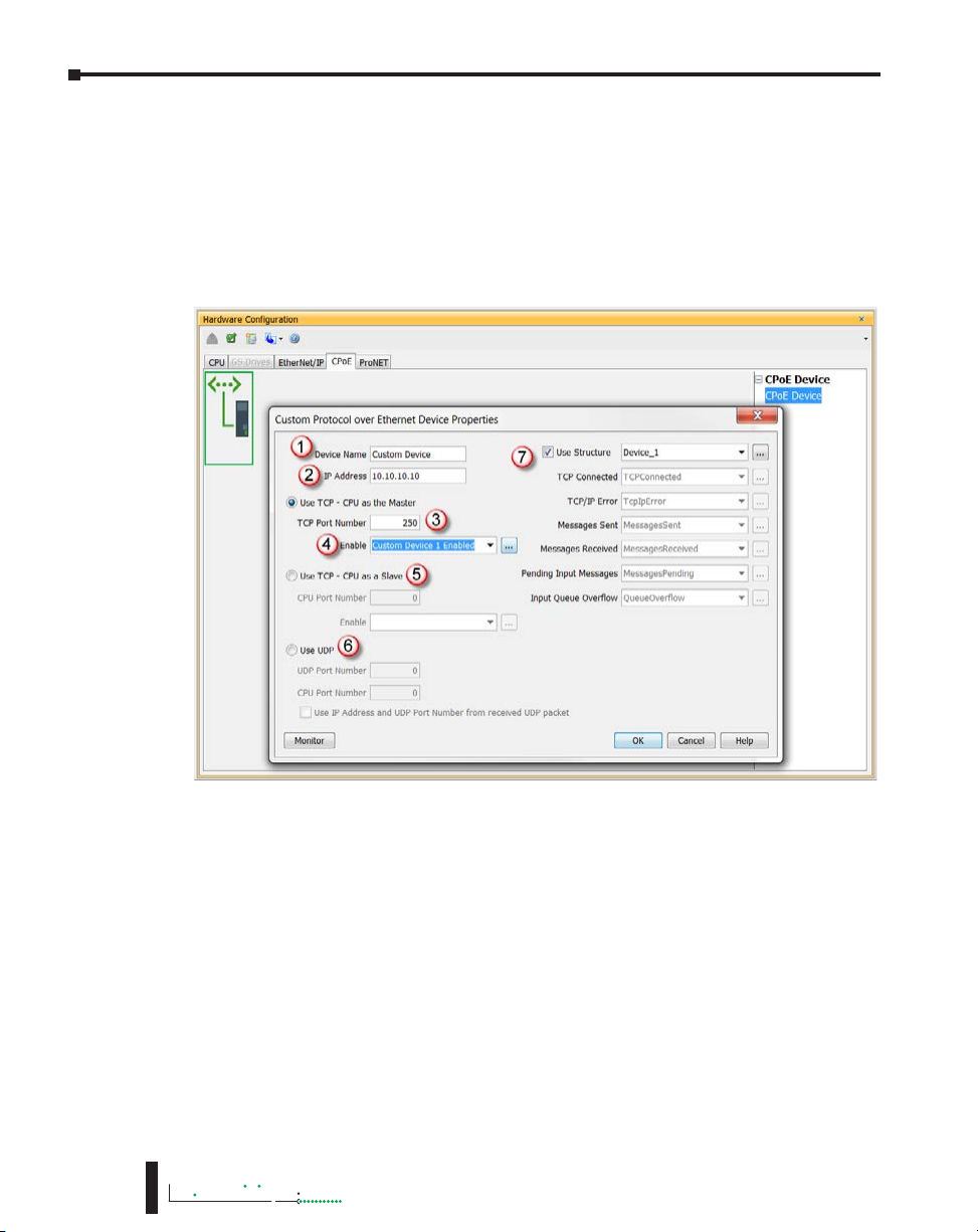
Chapter 6: Communications
Productivity
Hardware Configuration
First you must set up a device to talk to in the CPoE tab of the hardware configuration. This
will Require you to:
1. Enter a Device Name
2. Enter the IP Address of the device you wish to communicate with.
3. Enter the port number of the device.
4. Enter an Enable tag to enable the device if using TCP.
6-52
5. Choose whether you wish to Use the PLC as the master or the slave device via TCP connection
6. Choose whether you wish to use a UDP connection.
7. Enter tags for status of this device for troubleshooting (Example below shows the Structure method
used).
3000
Hardware User Manual, 4th Edition, Rev. M
Page 53

Productivity
3000
Custom Protocol Ethernet Instruction
Next you must use the Custom Protocol Ethernet instruction in ladder.
1. The instruction can be chosen Receive or Send messages to the Custom Device.
2. The user can choose to use:
•
A table with tags that allow the user to send a specific data.
• An array tag that is numerical can be used to Send/Receive from.
• A string tag that contains an ASCII string to be sent or string location to receive
characters to.
Chapter 6: Communications
Hardware User Manual, 4th Edition, Rev. M
6-53
Page 54

Chapter 6: Communications
Productivity
Communications: Remote I/O and GS-Drives
Things To Consider for the design of Remote I/O and GS-Drives
It is important to understand that only one Remote I/O network can be on an unmanaged
switch. If two or more Remote I/O networks are mixed into the same physical LAN (local
area network), duplicate IP addressing will occur and the system will not function properly.
Multiple Remote I/O networks can be used on a managed switch using the VLAN feature to
create a virtual separation of the different networks, but multicasting messages are necessary
for the network to function properly. Care must be taken when designing a system this way
(using a managed switch).
Even if only one Remote I/O network is being used in a facility, it is strongly recommended to
keep it on a dedicated network, physically isolated from other networks. As mentioned above,
the Productivity3000 Remote I/O network makes use of multi-casting messages and many
devices will not function properly in this situation.
The GS Drive configuration does not use multicasting in its setup but there are some initial
UDP broadcast messages that occur upon discovery when initiated from the software and at
power up. This should be considered if installing the GS Drive network with other devices.
C-more Panel
Modbus
TCP Device
6-54
Stride
Ethernet
Switch
3000
P3-550(E)
GS-EDRV100
GS-EDRV100
P3-RS
GSDrive
Stride
Ethernet
Switch
P3-550(E)
Hardware User Manual, 4th Edition, Rev. M
GS-
Drive
G
S
-
E
D
R
V
1
0
0
GS-
Drive
P3-RS
Page 55

Chapter 6: Communications
Productivity
3000
Configuration of Remote Slaves
NOTE: The P3-RS module is discontinued as of 6/20. Please use P3-RX as a replacement.
The Productivity3000® Remote I/O is very easy to configure. Each P3-RS or P3-RX Remote
Slave module’s address is set by rotary switches on the front of the module. The X1 switch is
used to set the least significant digit and the X10 switch is used to set the most significant digit.
So if the X10 switch were set to 2 and the X1 switch were set to 4, the Slave Address of that
module would be 24. Valid addresses are 01-99. 00 is not valid. Each slave module must have
a unique address and up to 16 slave units are allowed on a single system.
The address rotary switches are only read by the P3-RS/RX at power up. Power must be
cycled after an address change for it to take effect. Connect a straight through (patch) Ethernet
cable from the front of the P3-RS/RX module to an Ethernet switch. Connect a straight
through cable from the P3-550(E) Local Ethernet (Remote I/O) port (lower Ethernet port) to
the same switch. Open up the Productivity Suite Programming software and connect to the
P3-550(E). Once the software is connected, open Hardware Configuration. Select the “Read
Configuration” button in the upper left hand corner of this dialog and the P3-550(E) will
automatically discover the slave modules connected to the switch and return all found P3-RS/
RX modules and their configurations (bases and I/O modules).
CPU
Hardware User Manual, 4th Edition, Rev. M
6-55
Page 56

Chapter 6: Communications
Productivity
6-56
There are two fields that can be configured in regards to connectivity to the slave modules
(see the Local Ethernet Port Settings section of this chapter for a more detailed explanation of
these settings). The above diagram shows the CPU hardware configuration popup where these
settings can be found.
1. “Timeout between data query and response”: This is the time allowed (in 10 millisecond units)
between when the CPU sends a message to the P3-RS/RX and when a response is required. If
the CPU does not receive the response within the time specified, the outcome will depend on
how the P3-RS/RX and its I/O modules are configured:
CAUTION: If a timeout occurs and a module within a P3-RS/RX base or expansion base connected to
the P3-RS/RX has the “Automatic Module Verification” selection enabled, the CPU will go out of run
mode and a critical error will be generated.
3000
Hardware User Manual, 4th Edition, Rev. M
Page 57

Chapter 6: Communications
Productivity
3000
• If a timeout occurs but all of the modules within the P3-RS/RX base or expansion bases
connected to the P3-RS/RX have the “No Verification and Enable Hot Swap” selection
enabled and the P3-RS/RX module has the “Do not Detect if the Remote Base Group
is Disconnected” selection enabled (see above), the CPU will remain in Run and a noncritical error will be generated.
CAUTION: If a timeout occurs and the P3-RS/RX module has the “Automatic Remote Base Group
Detection” selection enabled, the CPU will go out of run mode and a critical error will be generated.
2. Comm Heartbeat Value: (previous page graphic) This value is used to help the P3-RS/RX
determine that the P3-550(E) is no longer communicating to it. If the P3-RS/RX module
does not receive a message from the P3-550(E) within the time frame specified in the “Comm
Heartbeat Value” field in the P3-550(E) configuration window, the P3-RS/RX module will turn
off all of its outputs.
Hardware User Manual, 4th Edition, Rev. M
6-57
Page 58

Chapter 6: Communications
Productivity
Configuration of GS-Drive Connections
GS Drive connections are set up in a
similar manner as the Remote Slaves. Set
a unique address for each GS-EDRV100
using its DIP switches. Or set the DIP
switches to 0 and select the address
using NetEdit (free download at
AutomationDirect.com). 01–64 are
valid addresses for a GS-EDRV100 in
a Productivity3000® system. Since the
DIP switch settings can only represent
00-63, setting a GS-EDRV100 to
address 64 must be done using NetEdit.
After the GS-EDRV100 modules’ addresses have been set, be sure to connect the serial
cable that comes with the GS-EDRV100 to the GS-Drive serial port. The GS-EDRV100
will automatically configure the GS-Drive serial port to the correct settings. Once the
GS-EDRV100 is properly addressed and connected to the GS-Drive, connect a straight
through (patch) Ethernet cable from the Ethernet port of the GS-EDRV100 to an Ethernet
switch. Connect a straight through cable from the P3-550(E) Local Ethernet Port (Remote
I/O) to the same switch.
Open the Productivity Suite Programming software and go online with the P3-550(E). Select
Setup and then Hardware Configuration. Select the “Read Configuration” button in the
upper left hand corner of this dialog and the P3-550(E) will automatically discover all of the
GS-EDRV100s connected to the switch and display all found GS-Drives.
GS-EDRV100 DIP
Switches
6-58
3000
Hardware User Manual, 4th Edition, Rev. M
Page 59

Chapter 6: Communications
Productivity
3000
Once the drives have been discovered, the configuration of each drive can be read and written
from the programming software.
To allow the P3-550(E) to automatically write the drive parameters on each CPU project
transfer and when the CPU is powered up, a setting must be configured in the P3-550(E)
project. Go to Tools and Options and select the “Project Transfer” tab. Select the “Transfer
GS drive configuration” as shown below. Drive parameters are ONLY transferred to the GS
Drive at project transfer or at boot up of the CPU.
Hardware User Manual, 4th Edition, Rev. M
6-59
Page 60

Chapter 6: Communications
Productivity
To monitor the status of the connection between the P3-550(E) and the GS-EDRV100 modules,
use the status bits of the GS Read and GS Write instructions as shown below. If a Timeout occurs
or an error is received, this can be monitored in the ladder code and appropriate action can be
taken.
The Communications Heartbeat function is configured differently for the GS Drives than
the Remote Slaves. Primarily because, as mentioned previously, there are two possible
communication paths that could be lost:
• P3-550(E) to GS-EDRV100.
• GS-EDRV100 to GS drive.
To configure the GS-EDRV100 and GS Drive to detect and react to loss of communications,
three parameters should be configured appropriately in the drive.
As shown below, parameter P9.03 determines what the drive will do when it detects loss of
communications. Parameter P9.04 enables the transmission loss detection feature. Parameter
P9.05 determines the amount of time the drive will wait for a transmission before assuming
that the link is lost and react according to how parameter P9.03 is configured.
6-60
The GS-EDRV100 reads these
configured parameters and if
they are configured for detecting
communications loss, it will also
monitor for loss of communications
on the Ethernet side. If
communications are lost on the
Ethernet side, the GS-EDRV100 will
shut down the GS Drive.
3000
Hardware User Manual, 4th Edition, Rev. M
Page 61

Productivity
3000
It is very important to note that if
the communications loss feature is
enabled; either a GS Drive Read or
GS Drive Write instruction needs
to be configured to communicate
to the GS-EDRV100 and GS Drive
at a poll rate that will prevent the
GS-EDRV100 and GS Drive from
detecting a loss of communication.
There is also a parameter
(P22.01) that can be monitored
to check the health of the
serial connection between the
GS-EDRV100 and the GS
Drive. This parameter can be
monitored in the ladder code
and appropriate action taken
if serial communications loss
is detected.
Chapter 6: Communications
Hardware User Manual, 4th Edition, Rev. M
6-61
Page 62

Chapter 6: Communications
Productivity
Communications: Port Configuration
The Communications Port Configuration
for any module containing comm ports is
accessed from the Hardware Configuration
window. For example, to access the P3-550(E)
communications port configuration, first select
Then select the P3-550(E) by
double left-clicking the CPU
or by right-clicking the CPU
and selecting Open from the
drop down list as seen above.
This will display the P3-550(E)
configuration window seen here.
Although the following
descriptions will focus on the
P3-550(E) communications ports,
the settings also apply to any other
module containing these ports
(P3-530, P3-RS, P3-RX).
the Local Base Group from the Hardware
Configuration window by double leftclicking the Local Base Group or by
right-clicking the Local Base Group and
selecting Open from the drop down menu
as seen above.
6-62
Ethernet Configuration
Ethernet Ports: There are two 10/100Base-T Ethernet ports on the P3-550(E) CPU.
• External Ethernet: The upper Ethernet port is referred to as the “External Ethernet Port”. This
port can connect to Modbus TCP Client devices, Modbus TCP Server devices and PCs running the
Productivity3000 programming software.
The External Ethernet Port is configured with an IP Address, Subnet Mask and Default Gateway,
allowing it to function seamlessly on a typical LAN network.
• Local Ethernet: The lower Ethernet (Remote I/O)port is referred to as the “Local Ethernet Port”. This
port functions as a Productivity3000 Remote I/O Client and also as a GS-Drive Client. The Local
Ethernet Port is not configurable and each CPU Remote I/O network should be located on its own
physical or logical network.
3000
Hardware User Manual, 4th Edition, Rev. M
Page 63

Chapter 6: Communications
Productivity
3000
NOTE: Two CPU Remote I/O networks cannot co-exist on the same LAN.
External Ethernet Port Settings
a. Port Name: Allows the entry of a unique Name for the External Ethernet Port. This Name is
referenced in the Communications instructions (MRX, MWX, RX, WX) to select the Port to
send the request from.
b. Port Security Option: This Option can be used as a simple Security measure to prevent Modbus
TCP write requests from being accepted by the CPU. To allow Reads and Writes, select Read/
Write.
c. TCP/IP Settings: The IP Setting of this Port may be changed in several ways:
• The Settings may be entered manually in the Choose CPU tool in the Productivity Suite
programming software. This allows the user to make changes to the IP to allow connection
by the computer running the Productivity Suite programming software. Changes are sent
using Multicast Messages.
• The Settings can be saved as part of the project. This must be Enabled in the P3-550(E)
Hardware Configuration Settings by selecting Use the Following (discussed on Item f
below). If handled this way, the Settings stored in the project will take effect at Project
Transfer and at boot up only. The Settings may be changed after boot up.
d. Use Current Settings: When selected, Project Transfer or boot up will not make changes to the
TCP/IP Settings of the CPU.
e. Use DHCP: This specifies that the CPU should request its IP Settings from a DHCP Server on
the network.
NOTE: If the CPU is set to use DHCP for it’s IP Settings it cannot, in all likelihood, be used as a Modbus
TCP Server.
f. Use The Following: If this Option is selected, the CPU will set itself to the specified project
Settings upon Project Transfer or at boot up.
g. IP Address: This field is where the IP Address is specified in Four Octets.
For Example: 192.168.1.5
h. Subnet Mask: This field is where the Subnet Mask is specified in Four Octets (i.e.,
255.255.255.0 ). The Subnet Mask is used in conjunction with the IP Address to configure a
Logical Network.
i. Default Gateway: This field is where the Default Gateway Address is specified in Four Octets
(i.e., 192.168.1.1). This is typically the IP Address of the router on the network. If a target IP
Address is specified in an outgoing message from the CPU
that is not in the Local Subnet, the Default Gateway Address
is where this message will be sent.
j. Timeout Between Data Query and Response: The Time
period specified in this field is the Time between the queries
sent from the CPU (via a Communication instruction, such
as a MRX, MWX, RX or WX) and the Time a response from
that device is received. If the Response takes longer to receive
(or is not received) than the specified Time period, a Timeout
Error will occur for the given instruction. Each instruction
has a Timeout Status bit that can be assigned to it. See the
diagram shown here.
Hardware User Manual, 4th Edition, Rev. M
6-63
Page 64

Chapter 6: Communications
Productivity
k. Modbus TCP Port: This is the listening TCP Port Number for Modbus TCP connections.
If necessary, this value can be adjusted for advanced router access. In most situations, this
Number should be left at 502.
l. Comm Heartbeat Value: This feature allows the ladder logic in the CPU to know if a device has
stopped communicating to the CPU. If a value is placed in this field, the CPU will start a timer
between each communication packet coming in to the CPU. If a communication packet fails
to be received by the CPU within the specified time period, the System Bit Ethernet Heartbeat
Timeout Bit will become true.
Local Ethernet Port Settings
m. Timeout Between Data Query and Response: The Time period specified in this field is the
Time between the queries sent from the CPU (for Remote I/O Nodes and GS Drive Nodes)
and the Time a Response from that device is Received. If the Response takes longer to receive
(or is not received) than the specified Time period, a Timeout Error will occur for the given
device and an Error will be generated in the Error Log. For P3-RS/RX Timeouts, the Error will
be critical or non-critical, dependent on the Hot-Swap settings for that unit, its I/O Modules
and P3-EX Bases. See Modbus Server diagram shown on previous page.
n. Comm Heartbeat Value: This value specifies how long the Remote I/O Slaves should wait for
a communication packet from the CPU. If a communication packet is not received from the
CPU within the specified time period, all outputs on the Remote Slave will be turned OFF.
Remote Access Configuration
6-64
a.. Web Server Function: Allows the ability to make a non secure web connection to the
P3-550(E) in order to access the USB pen drive and view read-only system tags. When
enabled, a port number selection is required.
• Port: (Default 80) Allows user to set a port number ranging from 1-65535.
b. Session Timeout: Allows the user to set a specific time limit (1-20 mins.) on inactivity that
will close the Web Server connection. If there is no activity between the PC and the Web
Server for the specified time limit, the connection will close.
c. Mobile Function: Enables Remote Access which allows the CPU Data Remote Monitor
App to monitor the selected tags.
d. Password Option: Allows the user to set a password for access to the Web Server.
• Enter an account name and password of up to a combination of 16 numbers and
characters (can include special characters).
3000
Hardware User Manual, 4th Edition, Rev. M
Page 65

Productivity
3000
Serial Configuration
Chapter 6: Communications
When the Serial Ports Tab is selected, the Serial Ports settings are displayed as shown below.
There are two Serial Ports on the P3-550(E) CPU. There is an RS-232 Port with an RJ-12
connector and a 2-wire RS-485 Port with a removable three point terminal block. Both Ports
are capable of Modbus RTU Client (device that initiates communications requests) and Server
(device that responds to communications requests) communications. They are also capable of
ASCII outgoing strings and incoming strings.
RS-232 and RS-485 Port Settings
a. Port Name: Allows the entry of a unique Name for the RS-232 and RS-485 Ports. This name
is referenced inside of the Communications instructions (MRX, MWX, RX, WX) and ASCII
instructions (AIN, AOUT, CPO, CPI) to select the Port to send or receive the request.
b. Port Security: This Option can be used as a simple Security measure to prevent Modbus TCP
write requests from being accepted by the CPU. To allow Reads and Writes, select Read/Write.
c. Protocol: This field determines whether the Port is used for Modbus RTU communications,
sending or receiving ASCII Strings or performing the Custom Protocol function.
d. Baud Rate: Choose the Baud Rate that your device and the CPU should communicate in this field.
The appropriate choice will vary greatly with device, application and environment. The important
point is that all devices communicating on the network need to be set to the same Baud Rate. The
available Baud Rates are 1200, 2400, 9600, 19200, 33600, 38400, 57600 and 115200 bps.
Hardware User Manual, 4th Edition, Rev. M
6-65
Page 66

Chapter 6: Communications
Productivity
e. Node Address: This field is used only when the CPU is a Modbus RTU Server device. This
field is used to uniquely identify the CPU on the network. This setting is also sometimes
referred to as a Station Address. This field can be set from 1 to 247.
f. Parity: The Parity Bit is used as a simple, low-level form of Error Detection. All devices on the
network need to be at the same Parity setting. The appropriate choice will vary with devices.
Valid selections are None, Even and Odd.
g. Data Bits: This field determines whether the communications packet uses Seven Data Bits or
Eight Data Bits. Eight Data Bits is the only valid selection for Modbus RTU. Either Seven or
Eight Data Bits can be selected when using ASCII communications. Set this field to match the
device that is connected to the CPU.
h. Stop Bits: This field determines whether the communications packet uses One or Two Stop
Bits. Set this field to match the device that is connected to the CPU.
i. Duplex Mode: In ASCII/Custom Protocol mode Half Duplex of Full Duplex can be chosen.
• Half Duplex: When selected, the serial port can either transmit or receive, but not both at the
same time.
• Full Duplex: When selected, allows the serial port to transmit and receive simultaneously.
(Only available in ASCII/Custom Protocol).
j. RTS Mode: Set the RTS mode to control the Request to Send signal out of the Serial Port.
k. RTS Off Delay Time (RS-232 Only): This Time period is the amount of Time between the
end of the data transmission to when the RTS signal is turned off. The diagram illustrates this.
This setting may be needed when using
media converters (RS-232 to RS-422/485
converters) and/or radio modems. A delay
may be needed at the end of the data
transmission for processing time in the
devices.
l. RTS On Delay Time (RS-232 Only): This Time period is the amount of Time between when the
RTS Signal is turned ON and the data transmission begins. The diagram illustrates this. This
setting may be needed when using media
converters (RS-232 to RS-485 converters)
and/or radio modems. A delay may be
needed after the assertion of the RTS
Signal and when the data transmission
begins for processing time in the device.
m. Timeout Between Query and Response:
The Time period specified in this field is the Time between
the queries sent from the CPU (via a Communication
instruction, such as an MRX, MWX, RX, or WX) and
the Time a Response from that device is Received. If the
Response takes longer to receive (or is not received) than
the specified Time period, a Timeout Error will occur for
the given instruction. Each instruction has a Timeout
Status bit that can be assigned to it.
6-66
3000
Hardware User Manual, 4th Edition, Rev. M
Page 67

Chapter 6: Communications
Productivity
3000
n. Modbus Character Timeout: The Modbus Character Delay Time is specified as the Time between
two bytes (or characters) within a given Modbus Message. The Modbus RTU specification
states that this time must be no more than 1.5
Character Times (real time based on Baud Rate).
Sometimes delays do occur between bytes when
using radio modems, media converters, etc.
This setting allows some tolerance in these
situations for the incoming Modbus Messages in
the CPU. The CPU will wait for the amount of
time specified in this field before discarding the incomplete packet. If the CPU does not receive
the remainder of the Message within the specified Time Frame, it will discard the first portion of
the Message and wait for a new Message.
o. Response/Request Delay (RS-485 Only): This setting is used when the CPU is a Modbus
RTU Server or Client on the RS-485 Port.
The total Response Time can be up to the Total CPU Scan Time + the Value specified in this
field. When using 2-wire RS-485 communications, sometimes Echoes can occur since both
devices use the same differential signal pair to send and receive.
• If acting as a Server (on left below), upon receiving a Modbus Request, the CPU will wait
for the time period specified in this field before sending a Response. This can be used
with slow clients that need extra time to change from sending to receiving.
• If acting as a Client (on right below), after receiving a Modbus Response, the CPU will
wait for the time period specified in this field before sending another Request. This can
be used to delay request messages in order to give extra time for slow server devices.
p. Comm Heartbeat Value: This feature allows the ladder logic in the CPU to know if a device
has stopped communicating to the CPU. If a value is placed in this field, the CPU will start a
timer between each communication packet coming in to the CPU. If a communication packet
fails to be received by the CPU within the specified Time period, the System Bit RS-232
Heartbeat Timeout Bit or RS-485 Heartbeat Timeout Bit will become true.
Hardware User Manual, 4th Edition, Rev. M
6-67
Page 68

Chapter 6: Communications
Productivity
Communications: Error Codes
NOTE: The only time you will see Communications Error Codes is when the CPU is the Master of a
Communications Network.
To simplify the process of identifying a possible Error, the Productivity3000® CPU will
automatically report to a specific memory location an Error Code that helps identify the
existing issue. The Error Codes are reported in the Exception Response String Tag specified in
the instruction as shown below.
The Exception Response String field is available on the following instructions:
• GS Drives Read • GS Drives Write • Modbus Read
• Modbus Write • Network Read • Network Write
• Dataworx Request
6-68
The Table shown below provides a list of Productivity3000 Communication Error Codes that
may be reported by the Productivity CPU.
Productivity3000 Communication Error Codes
Error Code Description Suggested Fix
01
02
03
04
06
Function Code not supported
Address out of range. This error is typically
generated when a Modbus address has been
requested that does not exist in the CPU.
Illegal Data Value. This error is typically
generated when the Modbus request sent to
the CPU is formed incorrectly.
Device Failure Check connected device
Slave Device is Busy. This error is typically
due to excess communications to the EDRV.
3000
Hardware User Manual, 4th Edition, Rev. M
Check instruction or connected device
and correct Function code or address
range selected.
Check instruction or connected device
and correct Function code or address
range selected.
Check the Modbus request against the
Modbus protocol specication (www.
modbus.org) to verify that it was formed
correctly.
Slow down the poll rate in the GS
instruction.
Page 69

Productivity
3000
P3000 EtherNet/IP Error Codes
Note: Other adapters may generate this error
CPU server currently supported errors
P3000 EtherNet/IP Error Codes
General
Status Error
0x01 0x0100
0x01 0x0103
0x01 0x0106
0x01 0x0107
0x01 0x0108
0x01 0x0109
Extended Status
Error
Name Description
A connection is already established from the target
Connection In Use/
Duplicate Forward
Open
Transport Class/
Trigger Combination
not supported
Owner Conict
Target Connection
Not Found
Invalid Network
Connection
Parameter
Invalid Connection
Size
device sending a Forward Open request or the target
device has sent multiple forward open request. This
could be caused by poor network trafc. Check the
cabling, switches and connections.
The Transport class and trigger combination is not
supported. The Productivity3000 CPU only supports
Class 1 and Class 3 transports and triggers: Change of
State and Cyclic.
An existing exclusive owner has already congured a
connection to this Connection Point. Check to see if
other Scanner devices are connected to this adapter
or verify that Multicast is supported by adapter device
if Multicast is selected for Forward Open. This could
be caused by poor network trafc. Check the cabling,
switches and connections.
This occurs if a device sends a Forward Close on a
connection and the device can’t nd this connection.
This could occur if one of these devices has powered
down or if the connection timed out on a bad
connection. This could be caused by poor network
trafc. Check the cabling, switches and connections.
This error occurs when one of the parameters
specied in the Forward Open message is not
supported such as Connection Point, Connection type,
Connection priority, redundant owner or exclusive
owner. The Productivity3000 CPU does not return
this error and will instead use errors 0x0120, 0x0121,
0x0122, 0x0123, 0x0124, 0x0125 or 0x0132 instead.
This error occurs when the target device doesn’t
support the requested connection size. Check the
documentation of the manufacturer’s device to verify
the correct Connection size required by the device.
Note that most devices specify this value in terms of
bytes. The Productivity3000 CPU does not return this
error and will instead use errors 0x0126, 0x0127 and
0x0128.
Chapter 6: Communications
CPU server (will not generate error)
P3000
Supported
0x01 0x0110
0x01 0x0111
Target for
Connection Not
Congured
RPI Not Supported
This error occurs when a message is received with a
connection number that does not exist in the target
device. This could occur if the target device has
powered down or if the connection timed out. This
could be caused by poor network trafc. Check the
cabling, switches and connections.
This error occurs if the Originator is specifying an RPI
that is not supported. The Productivity3000 CPU will
accept a minimum value of 10ms on a CIP Forward
Open request. However, the CPU will produce at the
specied rate up to the scan time of the installed
project. The CPU cannot product any faster than the
scan time of the running project.
Hardware User Manual, 4th Edition, Rev. M
6-69
Page 70

Chapter 6: Communications
Productivity
P3000 EtherNet/IP Error Codes
General
Extended Status
Status Error
0x01 0x0112
0x01 0x0113
0x01 0x0114
0x01 0x0115
0x01 0x0116
0x01 0x0117
0x01 0x0118
0x01 0x0119
Error
Name Description
This error can be returned if the Originator is
specifying an RPI value that is not acceptable. There
may be six additional values following the extended
error code with the acceptable values. An array can
be dened for this eld in order to view the extended
error code attributes. If the Target device supports
extended status, the format of the values will be as
shown below:
• Unsigned Integer 16, Value = 0x0112, Explanation:
Extended Status code
• |Unsigned Integer 8, Value = variable, Explanation:
Acceptable Originator to Target RPI type, values:
RPI Value not
acceptable
Out of Connections
Vendor ID or Product
Code Mismatch
Device Type
Mismatch
Revision Mismatch
Invalid Produced
or Consumed
Application Path
Invalid or
Inconsistent
Conguration
Application Path
Non-listen Only
Connection Not
Opened
0 = The RPI specied in the forward open was
acceptable (O -> T value is ignored), 1 = unspecied
(use a different RPI), 2 = minimum acceptable RPI
(too fast), 3 = maximum acceptable RPI (too slow),
4 = required RPI to corrected mismatch (data is
already being consumed at a different RPI), 5 to 255
= reserved.
• Unsigned Integer 32, Value = variable, Explanation:
Value of O -> T RPI that is within the acceptable
range for the application.
• Unsigned Integer 32, Value = variable, Explanation:
Value of T -> O RPI that is within the acceptable
range for the application.
The Productivity3000 EtherNet/IP Adapter connection
limit of 4 when doing Class 3 connections has been
reached. An existing connection must be dropped in
order for a new one to be generated.
The compatibility bit was set in the Forward Open
message but the Vendor ID or Product Code did not
match.
The compatibility bit was set in the Forward Open
message but the Device Type did not match.
The compatibility bit was set in the Forward Open
message but the major and minor revision numbers
were not a valid revision.
This error is returned from the Target device when the
Connection Point parameters specied for the O -> T
(Output) or T -> O (Input) connection is incorrect or not
supported. The Productivity3000 CPU does not return
this error and uses the following error codes instead:
0x012A, 0x012B or 0x012F.
This error is returned from the Target device when
the Connection Point parameter specied for the
Conguration data is incorrect or not supported. The
Productivity3000 CPU does not return this error and
uses the following error codes instead: 0x0129 or
0x012F.
This error code is returned when an Originator device
attempts to establish a listen only connection and
there is no non-listen only connection established.
The Productivity3000 CPU does not support listen only
connections as Scanner or Adapter.
P3000
Supported
6-70
3000
Hardware User Manual, 4th Edition, Rev. M
Page 71

Productivity
3000
P3000 EtherNet/IP Error Codes
Chapter 6: Communications
General
Extended Status
Status Error
0x01 0x011A
0x01 0x011B
0x01 0x011C
0x01 0x011D
0x01 0x011E
0x01 0x011F
0x01 0x0120
0x01 0x0121
0x01 0x0122
0x01 0x0123
0x01 0x0124
0x01 0x0125
0x01 0x0126
Error
Name Description
Target Object Out of
Connections
RPI is smaller than
the Production
Inhibit Time
Transport Class Not
Supported
Production Trigger
Not Supported
Direction Not
Supported
Invalid Originator
to Target Network
Connection Fixed/
Variable Flag
Invalid Target to
Originator Network
Connection Fixed/
Variable Flag
Invalid Originator
to Target Network
Connection Priority
Invalid Target to
Originator Network
Connection Priority
Invalid Originator
to Target Network
Connection Type
Invalid Target to
Originator Network
Connection Type
Invalid Originator
to Target Network
Connection
Redundant_Owner
Invalid Conguration
Size
The maximum number of connections supported by
this instance of the object has been exceeded.
The Target to Originator RPI is smaller than the Target
to Originator Production Inhibit Time. Consult the
manufacturer’s documentation as to the minimum
rate that data can be produced and adjust the RPI to
greater than this value.
The Transport Class requested in the Forward Open is
not supported. Only Class 1 and Class 3 classes are
supported in the Productivity3000 CPU.
The Production Trigger requested in the Forward Open
is not supported. In Class 1, only Cyclic and Change
of state are supported in the Productivity3000 CPU. In
Class 3, Application object is supported.
The Direction requested in the Forward Open is not
supported.
The Originator to Target xed/variable ag specied
in the Forward Open is not supported . Only Fixed is
supported in the Productivity3000 CPU.
The Target to Originator xed/variable ag specied
in the Forward Open is not supported. Only Fixed is
supported in the Productivity3000 CPU.
The Originator to Target Network Connection Priority
specied in the Forward Open is not supported. Low,
High, Scheduled and Urgent are supported in the
Productivity3000 CPU.
The Target to Originator Network Connection Priority
specied in the Forward Open is not supported. Low,
High, Scheduled and Urgent are supported in the
Productivity3000 CPU.
The Originator to Target Network Connection Type
specied in the Forward Open is not supported. Only
Unicast is supported for O -> T (Output) data in the
Productivity3000 CPU.
The Target to Originator Network Connection Type
specied in the Forward Open is not supported.
Multicast and Unicast is supported in the
Productivity3000 CPU. Some devices may not support
one or the other so if this error is encountered try the
other method.
The Originator to Target Network Connection
Redundant_Owner ag specied in the Forward Open
is not supported. Only Exclusive owner connections
are supported in the Productivity3000 CPU.
This error is returned when the Conguration data sent
in the Forward Open does not match the size specied
or is not supported by the Adapter. The Target device
may return an additional Unsigned Integer 16 value
that species the maximum size allowed for this data.
An array can be dened for this eld in order to view
the extended error code attributes.
P3000
Supported
Hardware User Manual, 4th Edition, Rev. M
6-71
Page 72

Chapter 6: Communications
Productivity
P3000 EtherNet/IP Error Codes
General
Status Error
0x01 0x0127
0x01 0x0128
0x01 0x0129
0x01 0x012A
0x01 0x012B
0x01 0x012C
0x01 0x012D
0x01 0x012E
0x01 0x012F
Extended
Status Error
Name Description
This error is returned when the Originator to Target (Output
data) size specied in the Forward Open does not match what
is in the Target. Consult the documentation of the Adapter
device to verify the required size. Note that if the Run/Idle
header is requested, it will add 4 additional bytes and must
be accounted for in the Forward Open calculation. The
Productivity3000 CPU always requires the Run/Idle header
Invalid Originator to
Target Size
Invalid Target to
Originator Size
Invalid
Conguration
Application Path
Invalid Consuming
Application Path
Invalid Producing
Application Path
Cong. Symbol
Does not Exist
Consuming Symbol
Does not Exist
Producing Symbol
Does not Exist
Inconsistent
Application Path
Combination
so if the option doesn’t exist in the Scanner device, you
must add an additional 4 bytes to the O -> T (Output) setup.
Some devices may publish the size that they are looking for
as an additional attribute (Unsigned Integer 16 value) of the
Extended Error Code. An array can be dened for this eld in
order to view the extended error code attributes.
NOTE: This error may also be generated when a Connection
Point value that is invalid for IO Messaging (but valid for
other cases such as Explicit Messaging) is specied, such as
0. Please verify if the Connection Point value is valid for IO
Messaging in the target device.
This error is returned when the Target to Originator (Input
data) size specied in the Forward Open does not match
what is in Target. Consult the documentation of the Adapter
device to verify the required size. Note that if the Run/Idle
header is requested, it will add 4 additional bytes and must
be accounted for in the Forward Open calculation. The
Productivity3000 CPU does not support a Run/Idle header for
the T -> O (Input) data. Some devices may publish the size
that they are looking for as an additional attribute (Unsigned
Integer 16 value) of the Extended Error Code. An array can be
dened for this eld in order to view the extended error code
attributes.
NOTE: This error may also be generated when a Connection
Point value that is invalid for IO Messaging (but valid for
other cases such as Explicit Messaging) is specied, such as
0. Please verify if the Connection Point value is valid for IO
Messaging in the target device.
This error will be returned by the Productivity3000 CPU if a
Conguration Connection with a size other than 0 is sent to
the CPU. The Conguration Connection size must always be
zero if it this path is present in the Forward Open message
coming from the Scanner device.
This error will be returned by the Productivity3000 CPU if the
Consuming (O -> T) Application Path is not present in the
Forward Open message coming from the Scanner device or if
the specied Connection Point is incorrect.
This error will be returned by the Productivity3000 CPU if
the Producing (T -> O) Application Path is not present in the
Forward Open message coming from the Scanner device or if
the specied Connection Point is incorrect.
The Originator attempted to connect to a conguration tag
name that is not supported in the Target.
The Originator attempted to connect to a consuming tag name
that is not supported in the Target.
The Originator attempted to connect to a producing tag name
that is not supported in the Target.
The combination of Conguration, Consuming and Producing
application paths specied are inconsistent.
P3000
Supported
6-72
3000
Hardware User Manual, 4th Edition, Rev. M
Page 73

Productivity
3000
P3000 EtherNet/IP Error Codes
Chapter 6: Communications
General
Extended Status
Status Error
0x01 0x0130
0x01 0x0131
0x01 0x0132
0x01 0x0133
0x01 0x0203
0x01 0x0204
0x01 0x0205
0x01 0x0206
0x01 0x0207
0x01 0x0301
0x01 0x0302
0x01 0x0303
0x01 0x0304
Error
Name Description
Inconsistent
Consume data
format
Inconsistent Product
data format
Null Forward
Open function not
supported
Connection Timeout
Multiplier not
acceptable
Connection Timed
Out
Unconnected
Request Timed Out
Parameter Error
in Unconnected
Request Service
Message Too
Large for
Unconnected_Send
Service
Unconnected
Acknowledge
without Reply
No Buffer Memory
Available
Network Bandwidth
not Available for
Data
No Consumed
Connection ID Filter
Available
Not Congured to
Send Scheduled
Priority Data
Information in the data segment not consistent with
the format of the data in the consumed data.
Information in the data segment not consistent with
the format of the data in the produced data.
The target device does not support the function
requested in the NULL Forward Open request. The
request could be such items as “Ping device”,
“Congure device application”, etc.
The Connection Multiplier specied in the Forward
Open request not acceptable by the Target device
(once multiplied in conjunction with the specied
timeout value). Consult the manufacturer device’s
documentation on what the acceptable timeout and
multiplier are for this device.
This error will be returned by the Productivity3000
CPU if a message is sent to the CPU on a connection
that has already timed out. Connections time out
if no message is sent to the CPU in the time period
specied by the RPI rate X Connection multiplier
specied in the Forward Open message.
This time out occurs when the device sends an
Unconnected Request and no response is received
within the specied time out period. In the
Productivity3000 CPU, this value may be found in
the hardware conguration under the Ethernet port
settings for the P3-550(E) or P3-530.
This error occurs when Connection Tick Time/
Connection time-out combination is specied in the
Forward Open or Forward Close message this is not
supported by the device.
Occurs when Unconnected_Send message is too large
to be sent to the network.
This error occurs if an Acknowledge was received but
no data response occurred. Verify that the message
that was sent is supported by the Target device using
the device manufacturer’s documentation.
This error occurs if the Connection memory buffer in
the target device is full. Correct this by reducing the
frequency of the messages being sent to the device
and/or reducing the number of connections to the
device. Consult the manufacturer’s documentation for
other means of correcting this.
This error occurs if the Producer device cannot
support the specied RPI rate when the connection
has been congured with schedule priority.
Reduce the RPI rate or consult the manufacturer’s
documentation for other means to correct this.
This error occurs if a Consumer device doesn’t have
an available consumed_connection_id lter.
This error occurs if a device has been congured for
a scheduled priority message and it cannot send the
data at the scheduled time slot.
P3000
Supported
Hardware User Manual, 4th Edition, Rev. M
6-73
Page 74

Chapter 6: Communications
Productivity
P3000 EtherNet/IP Error Codes
General
Extended Status
Status Error
0x01 0x0305
0x01 0x0306
0x01 0x0311
0x01 0x0312
0x01 0x0315
0x01 0x0316
0x01 0x0317
0x01 0x0318
0x01 0x0319
0x01 0x031A
0x01 0x031B
0x01 0x031C
0x01 0x031D
0x01 0x031E
Error
Name Description
Schedule Signature
Mismatch
Schedule Signature
Validation not
Possible
Port Not Available
Link Address Not
Valid
Invalid Segment in
Connection Path
Forward Close
Service Connection
Path Mismatch
Scheduling Not
Specied
Link Address to Self
Invalid
Secondary Resource
Unavailable
Rack Connection
Already established
Module Connection
Already established
Miscellaneous
Redundant
Connection
Mismatch
No more User
Congurable Link
Resources Available
in the Producing
Module
This error occurs if the schedule priority information
does not match between the Target and the Originator.
This error occurs when the schedule priority
information sent to the device is not validated.
This error occurs when a port number specied
in a port segment is not available. Consult the
documentation of the device to verify the correct port
number.
The Link address specied in the port segment is not
correct. Consult the documentation of the device to
verify the correct port number.
This error occurs when the target device cannot
understand the segment type or segment value in the
Connection Path. Consult the documentation of the
device to verify the correct segment type and value. If
a Connection Point greater than 255 is specied this
error could occur.
This error occurs when the Connection path in
the Forward Close message does not match the
Connection Path congured in the connection.
Contact Tech Support if this error persists.
This error can occur if the Schedule network segment
or value is invalid.
If the Link address points back to the originator
device, this error will occur.
This occurs in a redundant system when the
secondary connection request is unable to duplicate
the primary connection request.
The connection to a module is refused because part or
all of the data requested is already part of an existing
rack connection.
The connection to a rack is refused because part or
all of the data requested is already part of an existing
module connection.
This error is returned when there is no other
applicable code for the error condition. Consult
the manufacturer’s documentation or contact Tech
support if this error persist.
This error occurs when these parameters don’t match
when establishing a redundant owner connection: O
-> T RPI, O -> T Connection Parameters, T -> O RPI, T
-> O Connection Parameters and Transport Type and
Trigger.
This error is returned from the Target device when no
more available Consumer connections available for a
Producer.
P3000
Supported
6-74
3000
Hardware User Manual, 4th Edition, Rev. M
Page 75

Productivity
3000
P3000 EtherNet/IP Error Codes
Chapter 6: Communications
General
Extended Status
Status Error
0x01 0x031F
0x01 0x0800
0x01 0x0810
0x01 0x0811
0x01 0x0812
0x01 0x0813
0x01 0x0814
0x02 N/A
0x04 N/A
0x09 Index to error
0x0C Optional
0x10 Optional
Error
Name Description
No User
Congurable
Link Consumer
Resources
Congured in the
Producing Module
Network Link Ofine The Link path is invalid or not available.
No Target
Application Data
Available
No Originator
Application Data
Available
Node Address has
changed since
the Network was
scheduled
Not Congured for
Off-subnet Multicast
Invalid Produce/
Consume Data
format
Resource
Unavailable for
Unconnected Send
Path Segment Error
in Unconnected
Send
Error in Data
Segment
Object State Error
Device State Error
This error is returned from the Target device when no
Consumer connections have been congured for a
Producer connection.
This error is returned from the Target device when the
application has no valid data to produce.
This error is returned from the Originator device when
the application has no valid data to produce.
This species that the router has changed node
addresses since the value congured in the original
connection.
The producer has been requested to support a
Multicast connection for a consumer on a different
subnet and does not support this functionality.
Information in the data segment not consistent with
the format of the data in the consumed or produced
data. Errors 0x0130 and 0x0131 are typically used for
this situation in most devices now.
The Target device does not have the resources to
process the Unconnected Send request.
The Class, Instance or Attribute value specied in the
Unconnected Explicit Message request is incorrect
or not supported in the Target device. Check the
manufacturer’s documentation for the correct codes
to use.
This error code is returned when an error is
encountered in the Data segment portion of a Forward
Open message. The Extended Status value is the
offset in the Data segment where the error was
encountered.
This error is returned from the Target device when the
current state of the Object requested does not allow it
to be returned. The current state can be specied in
the Optional Extended Error status eld.
This error is returned from the Target device when the
current state of the Device requested does not allow it
to be returned. The current state can be specied in
the Optional Extended Error status eld.
P3000
Supported
0x13 N/A
0x15 N/A
Not Enough Data
Too Much Data
Not enough data was supplied in the service request
specied.
Too much data was supplied in the service request
specied.
Hardware User Manual, 4th Edition, Rev. M
6-75
 Loading...