

Page 1

AKD®-C and AKD®-N
EtherCAT Communication
Edition: J, October 2020
Valid for firmware version 1.20
Part Number 903-200023-00
Original Documentation
For safe and proper use, follow these
instructions. Keep for future use.
Page 2

Record of Document Revisions
Revision Remarks
... Table with lifecycle information of this document see "Record of Docu-
G, 11/2018 Updated object information.
H, 11/2019 Added Emergency Messages
J, 10/2020 Added objects 34D1h, 547Ah, 547Bh and edited data types for objects
Trademarks
l AKD is a registered trademark of Kollmorgen Corporation
l SynqNet is a registered trademark of Motion Engineering Inc.
l EnDat is a registered trademark of Dr. Johannes Heidenhain GmbH
l EtherCAT is a registered trademark and patented technology, licensed by Beckhoff
Automation GmbH
l Ethernet/IP is a registered trademark of ODVA, Inc.
l Ethernet/IP Communication Stack: copyright (c) 2009, Rockwell Automation
l sercos
l HIPERFACE is a registered trademark of Max Stegmann GmbH
l PROFINET is a registered trademark of PROFIBUS and PROFINET International (PI)
l SIMATIC is a registered trademark of SIEMENS AG
l SpeedTec is a registered trademark of TE Connectivity Industrial GmbH
l Windows is a registered trademark of Microsoft Corporation
®
is a registered trademark of sercos®international e.V.
ment Revisions" (➜ p. 178)
2001h and 2012.
Current patents
l US Patent 8,154,228 (Dynamic Braking For Electric Motors)
l US Patent 8,214,063 (Auto-tune of a Control System Based on Frequency Response)
Technical changes which improve the performance of the device may be made without prior notice!
This document is the intellectual property of Kollmorgen. All rights reserved. No part of this work may be reproduced
in any form (by photocopying, microfilm or any other method) or stored, processed, copied or distributed by electronic
means without the written permission of Kollmorgen.
2 Kollmorgen | kdn.kollmorgen.com | October 2020
Page 3

AKD-C/N EtherCAT | Table of Contents
1 Table of Contents
1 Table of Contents 3
2 General 9
2.1 About this Manual 10
2.2 Target Group 10
2.3 Symbols Used 11
2.4 Abbreviations Used 12
3 Installation and Setup 13
3.1 Important Instructions 14
3.2 EtherCAT Onboard 15
3.2.1 LED functions 15
3.2.2 Connection technology 15
3.2.3 Network Connection Example 15
3.3 Guide to Setup 16
3.4 Important Configuration Parameters 17
3.5 Setting up Ethernet over EtherCAT (EoE) 19
3.5.1 EtherCATDevice Settings 19
3.5.2 Drive Settings 20
3.5.3 Connecting to the Drive 20
3.5.4 Performance Concerns 21
3.5.5 Restrictions 21
3.6 Setup via TwinCAT NC/PTP System Manager 21
3.6.1 Scan devices 22
3.6.2 Select the device 22
3.6.3 Scan for boxes 23
3.6.4 Add Slaves to NC tasks 23
3.6.5 Enable the network configuration 23
3.6.6 Enable the axis and move the axis 24
3.7 Setup WorkBench over TwinCAT 25
3.7.1 TwinCAT and WorkBench Configuration 25
3.7.2 Connecting to a Drive Using WorkBench 27
3.7.3 Configuring and Enabling a Drive 30
3.7.4 Download a Parameter File over TwinCAT 31
3.8 Setup via KAS IDE 32
4 EtherCAT Profile 33
4.1 Slave Register 34
4.2 AL Event (Interrupt Event) and Interrupt Enable 35
4.2.1 Interrupt Enable Register (Address 0x0204:0x0205) 35
4.2.2 AL Event Request (Address 0x0220:0x0221) 36
4.3 Phase Run-Up 37
4.3.1 AL Control (Address 0x0120:0x0121) 37
4.3.2 AL Status (Address 0x0130:0x0131) 37
4.3.3 AL Status Code (Address 0x0134:0x0135) 38
4.3.4 EtherCAT communication phases 38
Kollmorgen | kdn.kollmorgen.com | October 2020 3
Page 4

AKD-C/N EtherCAT | Table of Contents
4.4 CANopen over EtherCAT (CoE) State Machine 39
4.4.1 Status Description 39
4.4.2 Commands in the Control Word 40
4.4.3 State Machine Bits (status word) 41
4.5 Fixed PDO Mappings 41
4.6 Flexible PDO Mappings 44
4.6.1 Example: Flexible PDO Mapping 45
4.6.2 Example: Flexible PDOMapping with one byte gap in Rx-PDO 49
4.7 Supported Cyclical Setpoint and Actual Values 51
4.8 Supported Operation Modes 54
4.9 Adjusting EtherCAT Cycle Time 54
4.10 Maximum Cycle Times depending on operation mode 54
4.11 Synchronization 55
4.11.1 Synchronization behavior with distributed clocks (DC) enabled 55
4.11.2 Synchronization behavior with distributed clocks (DC) disabled 55
4.12 Latch Control Word and Latch Status Word 56
4.13 Mailbox Handling 57
4.13.1 Mailbox Output 58
4.13.2 Mailbox Input 59
4.13.3 Example: Mailbox Access 60
4.14 EEProm Content 61
5 Appendix 62
5.1 CANopen Emergency Messages and Error Codes 63
5.1.1 Error Codes for Drives 63
5.1.2 Error Codes for Power Supply 68
5.2 Object Dictionary AKD-C 69
5.3 Object Dictionary AKD-N 73
5.3.1 Float Scaling 73
5.3.2 Communication SDOs 73
5.3.3 Manufacturer specific SDOs 76
5.3.4 Profile Specific SDOs 94
5.4 Object Descriptions 98
5.4.1 Object 1000h: Device Type (DS301) 98
5.4.2 Object 1001h: Error register (DS301) 98
5.4.3 Object 1002h: Manufacturer Status Register (DS301) 99
5.4.4 Object 1003h: Predefined Error Field (DS301) 100
5.4.5 Object 1005h: COB-ID of the SYNC Message (DS301) 101
5.4.6 Object 1006h: Communication Cycle Period (DS301) 101
5.4.7 Object 1008h: Manufacturer Device Name (DS301) 102
5.4.8 Object 1009h: Manufacturer Hardware Version 102
5.4.9 Object 100Ah: Manufacturer Software Version (DS301) 102
5.4.10 Object 100Ch: Guard Time (DS301)Response monitoring 103
5.4.11 Object 100Dh: Lifetime Factor (DS301) 103
5.4.12 Object 1010h: Store Parameters (DS301) 104
5.4.13 Object 1011h: Restore Default Parameters DS301 105
5.4.14 Object 1012h: COB-ID of the Time Stamp (DS301) 106
4 Kollmorgen | kdn.kollmorgen.com | October 2020
Page 5

AKD-C/N EtherCAT | Table of Contents
5.4.15 Object 1014h: COB-ID for Emergency Message (DS301) 106
5.4.16 Object 1016h: Consumer Heartbeat Time 107
5.4.17 Object 1017h: Producer Heartbeat Time 108
5.4.18 Object 1018h: Identity Object (DS301) 108
5.4.19 Object 1026h: OS Prompt 110
5.4.20 Objects 1400-1403h: 1st - 4th RxPDO communication parameter (DS301) 111
5.4.21 Objects 1600-1603h: 1st - 4th RxPDO mapping parameter (DS301) 112
5.4.22 Objects 1800-1803h: 1st - 4th TxPDO communication parameter (DS301) 113
5.4.23 Objects 1A00-1A03h: 1st - 4th TxPDO mapping parameter (DS301) 115
5.4.24 Object 1C12h: RxPDO assign (DS301) 116
5.4.25 Object 1C13h: TxPDO assign (DS301) 117
5.4.26 Object 1C32h: SM output parameter (DS301, AKD-C) 118
5.4.27 Object 1C33h: SM input parameter (DS301, AKD-C) 120
5.4.28 Object 2000h: SystemWarnings 121
5.4.29 Object 2001h: SystemFaults 122
5.4.30 Object 2002h: Manufacturer status bytes 122
5.4.31 Object 2011h: DRV.RUNTIME in seconds 123
5.4.32 Object 2012h: Fault history: Fault numbers 123
5.4.33 Object 2013h: Fault history: Time stamps 124
5.4.34 Object 2014-2017h: 1st-4th Mask 1 to 4 for Transmit-PDO 125
5.4.35 Object 2018h: Firmware Version 126
5.4.36 Object 2026h: ASCII Channel 127
5.4.37 Object 204Ch: PV Scaling Factor 128
5.4.38 Object 2071h: Target Current 129
5.4.39 Object 2077h: Current ActualValue 129
5.4.40 Object 207Fh: Maximum Velocity 129
5.4.41 Object 2080h: Motion Task Select 130
5.4.42 Object 2081h: Active Motion Task 130
5.4.43 Object 20A0h: Latch position 1, positive edge 130
5.4.44 Object 20A1h: Latch position 1, negative edge 131
5.4.45 Object 20A2h: Latch position 2, positive edge 131
5.4.46 Object 20A3h: Latch position 2, negative edge 132
5.4.47 Object 20A4h: Latch Control Register 132
5.4.48 Object 20A5h: Latch Status Register 133
5.4.49 Object 20A6h: Latch position 1, positive or negative edge 133
5.4.50 Object 20A7h: Latch position 2, positive or negative edge 134
5.4.51 Object 20B8h: Reset of changed input information 134
5.4.52 Object 345Ah: Brake Control 135
5.4.53 Object 3474h: Parameters for digital inputs 137
5.4.54 Object 3475h: Parameters for digital outputs 138
5.4.55 Object 3496h: Fieldbus synchronization parameters 139
5.4.56 Object 34D1h: Legacy EtherCAT input handling 141
5.4.57 Object 6040h: Control word (DS402) 141
5.4.58 Object 6041h: Status word (DS402) 143
5.4.59 Object 605Ah: Quick stop option code (DS402) 145
5.4.60 Object 6060h: Modes of Operation (DS402) 146
Kollmorgen | kdn.kollmorgen.com | October 2020 5
Page 6

AKD-C/N EtherCAT | Table of Contents
5.4.61 Object 6061h: Modes of Operation Display (DS402) 147
5.4.62 Object 6063h: position actual value* (DS402) 147
5.4.63 Object 6064h: position actual value (DS402) 148
5.4.64 Object 6065h: Following error window 148
5.4.65 Object 606Ch: Velocity actual value (DS402) 148
5.4.66 Object 6071h: Target torque (DS402) 149
5.4.67 Object 6073h: Max current (DS402) 149
5.4.68 Object 6077h: Torque actual value (DS402) 149
5.4.69 Object 607Ah: Target position (DS402) 150
5.4.70 Object 607Ch: Homing offset (DS402) 150
5.4.71 Object 607Dh: Software position limit (DS402) 151
5.4.72 Object 6081h: Profile velocity (DS402) 152
5.4.73 Object 6083h: Profile acceleration (DS402) 152
5.4.74 Object 6084h: Profile deceleration (DS402) 152
5.4.75 Object 6087h Torque slope (DS402) 153
5.4.76 Object 608Fh: Position encoder resolution (DS402) 153
5.4.77 Object 6091h: Gear Ratio (DS402) 154
5.4.78 Object 6092h: Feed constant (DS402) 155
5.4.79 Object 6098h: Homing method (DS402) 156
5.4.80 Object 6099h: Homing speeds (DS402) 158
5.4.81 Object 609Ah: Homing acceleration (DS402) 158
5.4.82 Object 60B1h: Velocity Offset 159
5.4.83 Object 60B2h: Torque Offset 159
5.4.84 Object 60B8h: Touch probe function 160
5.4.85 Object 60B9h: Touch probe status 161
5.4.86 Object 60BAh: Touch probe 1 positive edge 162
5.4.87 Object 60BBh: Touch probe 1 negative edge 162
5.4.88 Object 60BCh: Touch probe 2 positive edge 162
5.4.89 Object 60BDh: Touch probe 2 negative edge 163
5.4.90 Object 60C0h: Interpolation sub mode select 163
5.4.91 Object 60C1h: Interpolation data record 164
5.4.92 Object 60C2h: Interpolation time period 165
5.4.93 Object 60C4h: Interpolation data configuration 166
5.4.94 Object 60D0h: Touch probe source 168
5.4.95 Object 60E0h: Positive Torque Limit Value 169
5.4.96 Object 60E1h: Negative Torque Limit Value 169
5.4.97 Object 60E4h: Additional position actual value 170
5.4.98 Object 60E8h: Additional gear ratio – motor shaft revolutions 171
5.4.99 Object 60E9h: Additional feed constant – feed 172
5.4.100 Object 60EDh: Additional gear ratio – driving shaft revolutions 173
5.4.101 Object 60EEh: Additional feed constant - driving shaft revolutions 174
5.4.102 Object 60F4h: Following error actual value (DS402) 175
5.4.103 Object 60FCh: Position demand internal value (DS402) 175
5.4.104 Object 60FDh: Digital inputs (DS402) 175
5.4.105 Object 60FEh: Digital outputs (DS402) 176
5.4.106 Object 60FFh: Target velocity (DS402) 177
6 Kollmorgen | kdn.kollmorgen.com | October 2020
Page 7

AKD-C/N EtherCAT | Table of Contents
5.4.107 Object 6502h: Supported drive modes (DS402) 177
6 Record of Document Revisions 178
7 Index 179
Kollmorgen | kdn.kollmorgen.com | October 2020 7
Page 8

AKD-C/N EtherCAT | Table of Contents
--- / ---
8 Kollmorgen | kdn.kollmorgen.com | October 2020
Page 9

AKD-C/N EtherCAT | 2 General
2 General
2.1 About this Manual 10
2.2 Target Group 10
2.3 Symbols Used 11
2.4 Abbreviations Used 12
Kollmorgen | kdn.kollmorgen.com | October 2020 9
Page 10

AKD-C/N EtherCAT | 2 General
2.1 About this Manual
This manual, AKD-C/N EtherCAT Communication, describes the installation, setup, range of
functions, and software protocol for the decentral drive system with AKD-C and AKD-N
devices.
A digital version of this manual (pdf format) is available on the DVD included with your
device. Document updates can be downloaded from the Kollmorgen website.
Related documents for the AKD-C/N series include:
AKD-C Installation Manual – This manual provides instructions for installation and device
setup.
AKD-N Installation Manual – This manual provides instructions for installation and drive
setup.
AKD User Guide – This manual describes how to use your drive in common applications.
It also provides tips for maximizing your system performance with the AKD. The User
Guide includes the Parameter and Command Reference Guide which provides doc-
umentation for the parameters and commands used to program the AKD-C and AKD-N.
Accessories Manual – This manual provides documentation for accessories like cables
and regen resistors used with AKD-C and AKD-N. Regional versions of this manual exist.
Additionally, an EtherCAT XML file, entitled AKD EtherCAT Device Description, describes
the drive SDO and PDO. This file is available on the Kollmorgen website (part of the firmware
zip archive).
2.2 Target Group
This manual addresses personnel with the following qualifications:
The qualified personnel must know and observe the following standards:
Installation: only by electrically qualified personnel.
Setup: only by qualified personnel with extensive knowledge of electrical engineering
and drive technology.
Programming: software developers, project-planners.
ISO 12100, IEC 60364 and IEC 60664
National accident prevention regulations
10 Kollmorgen | kdn.kollmorgen.com | October 2020
Page 11
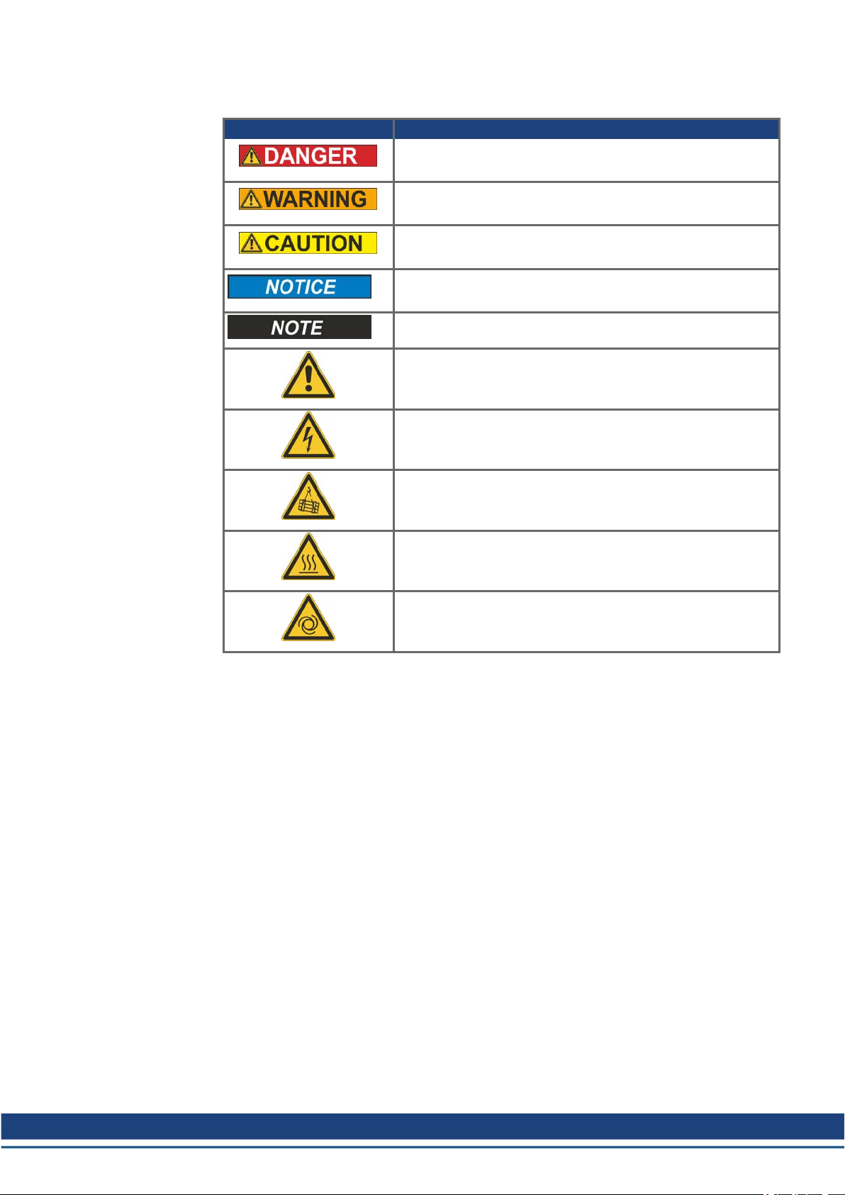
2.3 Symbols Used
Symbol Indication
AKD-C/N EtherCAT | 2 General
Indicates a hazardous situation which, if not avoided, will result in death or serious injury.
Indicates a hazardous situation which, if not avoided, could result in death or serious injury.
Indicates a hazardous situation which, if not avoided, could result in minor or moderate injury.
Indicates situations which, if not avoided, could result in property damage.
This symbol indicates important notes.
Warning of a danger (general). The type of danger is specified
by the text next to the symbol.
Warning of danger from electricity and its effects.
Warning of danger from suspended loads.
Warning of danger from high temperature.
Warning of danger from automatic start.
Kollmorgen | kdn.kollmorgen.com | October 2020 11
Page 12

AKD-C/N EtherCAT | 2 General
2.4 Abbreviations Used
Abbreviation Meaning
AL Application Layer: the protocol that directly used by the process entities.
Cat Category – classification for cables that is also used in Ethernet.
DC Distributed Clocks Mechanism to synchronize EtherCAT slaves and master
DL Data Link(=Layer 2). EtherCAT uses standardized Ethernet (IEEE 802.3)
ESC EtherCAT Slave Controller
FPGA Field Programmable Gate Array
FTP File Transfer Protocol
HW Hardware
ICMP Internet Control Message Protocol: Mechanisms for signaling IP errors.
IEC International Electrotechnical Commission: The international standards
IEEE Institute of Electrical and Electronics Engineers, Inc.
LLDP Link Layer Discovery Protocol
MAC Media Access Control
MII Media Independent Interface: Standardized interface Ethernet controller <-> routing
MDI Media Dependant Interface: Use of connector Pins and Signaling.
MDI-X Media Dependant Interface (crossed): Use of connector Pins and Signaling with
OSI Open System Interconnect
OUI Organizationally Unique Identifier – the first 3 Bytes of an Ethernet-Address, that
PDI Physical Device Interface: set of elements that allows access to ESC from the pro-
PDO Process Data Object
PDU Protocol Data Unit: Contains protocol information transferred from a protocol
PHY Physical interface that converts data from the Ethernet controller to electric or
PLL Phase Locked Loop
PTP Precision Time Protocol in accordance with IEEE 1588
RSTP Rapid Spanning Tree Protocol
RT Real-time, can be run in Ethernet controllers without special support.
RX Receive
RXPDO Receive PDO
SNMP Simple Network Management Protocol
SPI Serial Peripheral Interface
Src Addr Source Address: Source address of a message.
STP Shielded Twisted Pair
TCP Transmission Control Protocol
TX Transmit
TXPDO Transmit PDO
UDP User Datagram Protocol: Non-secure multicast/broadcast frame.
UTP Unshielded Twisted Pair
ZA ECAT Access mode EtherCAT
ZA Drive Acces mode drive
equipment.
crossed lines.
will be assign to companies or organizations and can be used for protocoll identifiers as well (e.g. LLDP)
cess side.
instance of transparent data to a subordinate level
optical signals.
12 Kollmorgen | kdn.kollmorgen.com | October 2020
Page 13

AKD-C/N EtherCAT | 3 Installation and Setup
3 Installation and Setup
3.1 Important Instructions 14
3.2 EtherCAT Onboard 15
3.3 Guide to Setup 16
3.4 Important Configuration Parameters 17
3.5 Setting up Ethernet over EtherCAT (EoE) 19
3.6 Setup via TwinCAT NC/PTP System Manager 21
3.7 Setup WorkBench over TwinCAT 25
3.8 Setup via KAS IDE 32
Kollmorgen | kdn.kollmorgen.com | October 2020 13
Page 14
AKD-C/N EtherCAT | 3 Installation and Setup
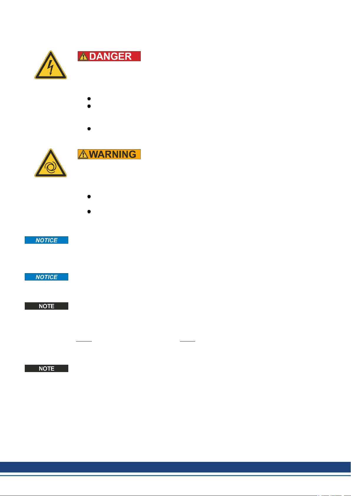
3.1 Important Instructions
There is a danger of serious personal injury or death by electrical shock or electrical arcing.
Capacitors can still have dangerous voltages present up to 7 minutes after switching off the
supply power. Control and power connections can still be live, even if the motor is not rotating.
Never remove electrical connections to the drive while it is live.
Wait at least seven minutes after disconnecting the drive from the main supply
power before touching potentially live sections of the equipment (e.g. contacts) or
undoing any connections.
To be sure, measure the voltage in the DC bus link and wait until it has fallen below
50 V.
Risk of death or serious injury for humans working in the machine. Drives with EtherCAT
are remote-controlled machines. They can start to move at any time without previous warning. The drive might restart automatically after power on, voltage dip or interruption of the
supply voltage, depending on the parameter setting.
Place a warning sign ("WARNING: Possible Automatic Start" or
similar) to the machine.
Ensure, that power on is not possible, while humans are in a
dangerous zone of the machine.
High Voltage up to 900 V!
Automatic Restart!
Install the drive as described in the Installation Manual. The wiring for the analog setpoint
input and the positioning interface, as shown in the wiring diagram in the Installation Manual,
is not required. Never break any of the electrical connections to the drive while it is live. This
action can result in destruction of the electronics.
The drive's status must be monitored by the PLC to acknowledge critical situations. Wire the
FAULT contact in series into the emergency stop circuit of the installation. The emergency
stop circuit must operate the supply contactor.
It is permissible to use the setup software to alter the settings of the drive. Any other alterations will invalidate the warranty. Because of the internal representation of the position-control parameters, the position controller can only be operated if the final limit speed of the drive
does not exceed:
rotary linear
at sinusoidal² commutation: 7500 rpm at sinusoidal² commutation: 4 m/s
at trapezoidal commutation: 12000 rpm. at trapezoidal commutation: 6.25 m/s
All the data on resolution, step size, positioning accuracy etc. refer to calculatory values.
Non-linearities in the mechanism (backlash, flexing, etc.) are not taken into account. If the
final limit speed of the motor must be altered, then all the parameters that were previously
entered for position control and motion blocks must be adapted.
14 Kollmorgen | kdn.kollmorgen.com | October 2020
Page 15
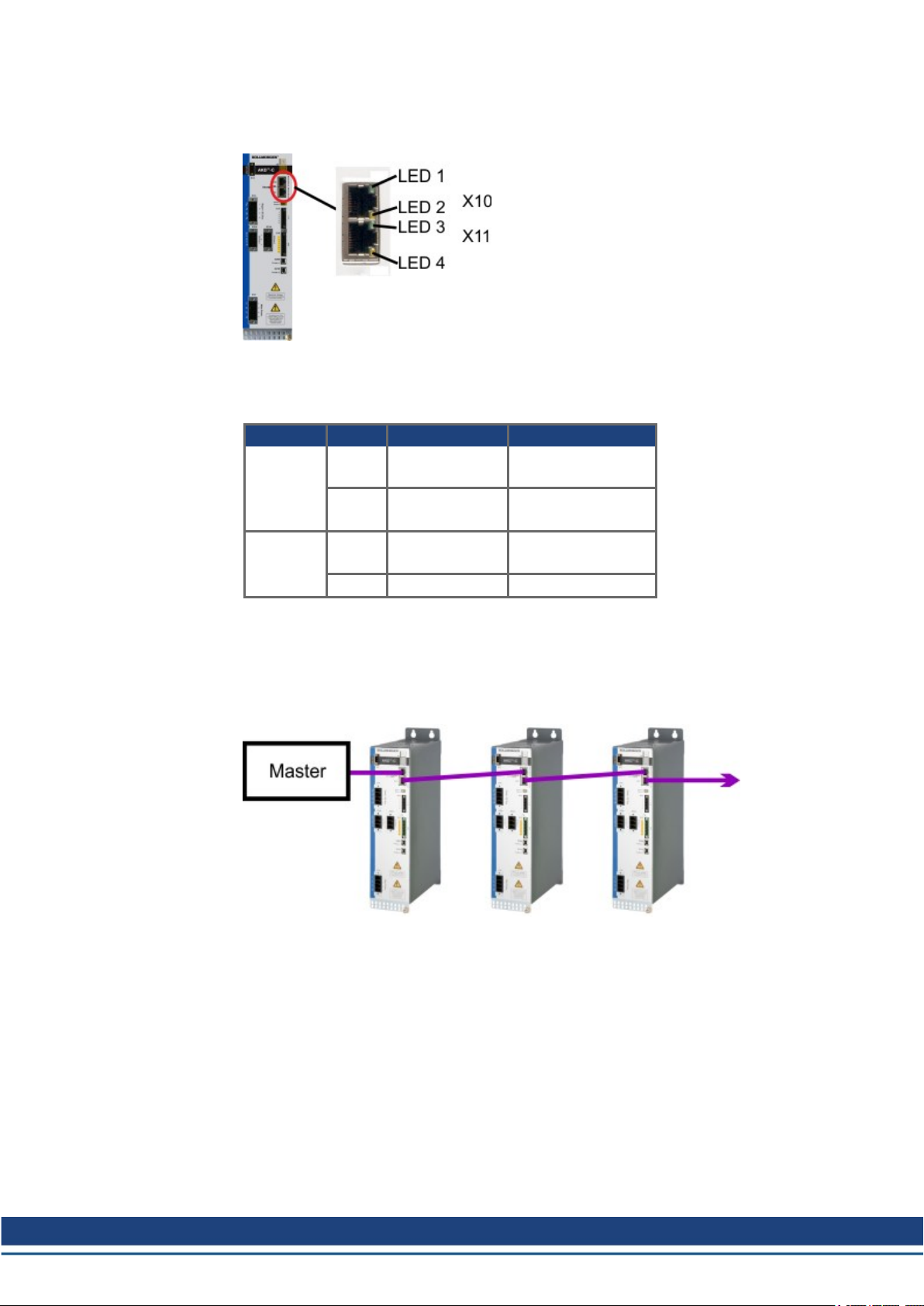
3.2 EtherCAT Onboard
Connection to the EtherCAT Network via X10 (in port) and X11 (out port).
3.2.1 LED functions
The communication status is indicated by the built-in LEDs.
Connector LED# Name Function
X10 LED1 IN port Link ON = active
X11 LED3 OUT port Link ON = active
AKD-C/N EtherCAT | 3 Installation and Setup
OFF= not active
LED2 RUN ON = running
OFF = not running
OFF = not active
LED4 - -
3.2.2 Connection technology
You can connect to the EtherCAT network using RJ-45 connectors.
3.2.3 Network Connection Example
Kollmorgen | kdn.kollmorgen.com | October 2020 15
Page 16

AKD-C/N EtherCAT | 3 Installation and Setup
3.3 Guide to Setup
Only professional personnel with extensive knowledge of control and drive technology are
allowed to setup the drive.
Risk of death or serious injury for humans working in the machine. Drives with EtherCAT
are remote-controlled machines. They can start to move at any time without previous warning. The drive might restart automatically after power on, voltage dip or interruption of the
supply voltage, depending on the parameter setting.
Place a warning sign ("WARNING: Possible Automatic Start" or
similar) to the machine.
Ensure, that power on is not possible, while humans are in a
dangerous zone of the machine.
Refer to chapter "Important Configuration Parameters" (➜ p. 17) for fieldbus parameter setting (FBUS.PARAMx).
1. Check assembly/installation. Check that all the safety instructions in the product manual
for the drive and this manual have been observed and implemented. Check the setting for
the station address and baud rate.
2. Connect PC,start WorkBench. Use the setup software WorkBench to set the parameters
for the drive.
3. Setup basic functions. Start up the basic functions of the drive and optimize the current,
speed and position controllers. This section of the setup is described in the in the online
help of the setup software.
4. Save parameters. When the parameters have been optimized, save them in the drive.
Automatic Restart!
16 Kollmorgen | kdn.kollmorgen.com | October 2020
Page 17

3.4 Important Configuration Parameters
The AKD holds several fieldbus-specific, general purpose parameters. Some of them contain
the following relevant data:
FBUS.PARAM01:
Sets the baud rate for the CANbus. Supported baud rates are 125, 250, 500 and 1000 kBaud.
On AKD-C, FBUS.PARAM01 sets and stores the EtherCAT station alias for the ESC (EtherCAT slave controller) of string 2.
FBUS.PARAM02:
This parameter activates the synchronization feature of the AKD. The DC feature must be
activated in order to allow the AKD to get synchronized with the master. Only works when
FBUS.TYPE= 3 (CANopen).
Drive internal PLL (phase locked loop) functionality: enabled (1),
Drive internal PLL functionality: disabled (0).
FBUS.PARAM03:
This parameter contains the Configured Station Alias address of the AKD. An EEPROM emulation write access to the Configured Station Alias address forces the AKD to store the drive
parameters automatically using the DRV.NVSAVE command. On AKD-C,
FBUS.PARAM03 sets and stores the EtherCAT station alias for the ESC (EtherCAT slave
controller) of string 1.
FBUS.PARAM04:
This parameter enables (1) or disables (0) the synchronization supervision of the CANOpen
or EtherCAT fieldbus.
Default values for this parameter are as follows:
CANopen drive: disabled (0)
EtherCAT drive: enabled (1)
Synchronization supervision is active when FBUS.PARAM 04 = 1 and the first CANOpen
Sync message or first EtherCAT frame is received. When more than three CANOpen sync
messages or seven EtherCAT frames have not been received and the drive is enabled, fault
F125 (“Synchronization lost“), occurs.
FBUS.PARAM05:
AKD-C/N EtherCAT | 3 Installation and Setup
Bit 0 1 Faults can only be reset using DS402 controlword bit 7.
0 The reset can also be done using Telnet or digital input and the DS402
state machine reflects this condition.
Bit 1 1 The state of the hardware enable does not change the state machine to
state Operation enable.
0 If the state Operation enable or Switched on is active, it falls back to the
state Switch on disabled, if the Hardware enable goes to 0.
Bit 2 1 WorkBench/Telnet cannot software enable the drive when
CANopen/EtherCAT are operational.
0 WorkBench/Telnet can software enable the drive.
During commissioning this bit should be set to 1 to
avoid influences to DS402 power stage state machine.
The fieldbus should not be in operation to avoid influence to test functions of WorkBench.
Bit 3 1 DS402 - state machine is not influenced if the software enable is taken
away using Telnet.
0 DS402 - state machine is influenced if the software enable is taken away
using Telnet.
Kollmorgen | kdn.kollmorgen.com | October 2020 17
Page 18

AKD-C/N EtherCAT | 3 Installation and Setup
Bit 4 1 Scaling is done using special DS402 - objects (independent on units)
0 Scaling for position, velocity and acceleration objects is done using UNIT
parameters.
Bit 5
1 FBUS.PARAM03 defines the station alias address if not 0. If
(EtherCAT
only)
FBUS.PARAM03 is set to 0, the address will be taken from rotary
switches if they are not 0. The EtherCAT master has the ability to use the
alias address selected by the drive or issue its own.
0 The rotary switches define the station alias address if not 0. If the rotary
switches are set to 0, the address is taken from FBUS.PARAM03 instead,
if it is not 0.
Bit 6 1 Bit 0 of parameter MT.CNTL (object 35B9 sub 0) can be accessed.
0 Bit 0 of parameter MT.CNTL (object 35B9 sub 0) is exclusively used for
DS402 controlword.
Bit 7 1 All capture objects (0x20A0-0x20A3, 0x20A6, 0x20A7, 0x60BA to
0x60BD) are scaled as object 0x6063.
0 All capture objects (0x20A0-0x20A3, 0x20A6, 0x20A7, 0x60BA to
0x60BD) are scaled as object 0x6064.
Bit 8 1 DS402 - state Switched on means power stage disabled.
0 DS402 - state Switched on means power stage enabled.
Bit 9 1 SDO content of object 0x6063 is the same as PDO content.
0 SDO content of object 0x6063 depends on AKD unit parameters.
Bit 10
(Bit 10 is act-
ive only,
if Bit 8 is set)
1 State Switched on can be reached without the high-level voltage being act-
ive.
0 State Switched on can only be reached when the high-level voltage is act-
ive; otherwise the drive stays in Ready to switch on.
Bit 11 1 No emergency messages over CANopen are triggered when a drive warn-
ing occurs.
0 Emergency messages over CANopen are triggered when a drive warning
occurs.
Bit 12 reserved
Bit 13
(EtherCAT
1 Downloaded parameter file is stored automatically to nonvolatile memory.
0 Downloaded parameter file is not stored automatically to nonvolatile
only)
memory.
Bit 14 1 If a warning occurs which limits a movement of the motor bit 11 in the
DS402 statusword is additionally set to bit 7.
0 Only bit 7 is set when any warning occurs.
Bit 15 1 The bit 10 of the statusword (target reached) is also set as a reaction to the
halt bit (bit 8) of the controlword when the motor velocity is below
CS.VTHRESH.
0 Bit 10 of the statusword is only set when the external setpoint value of a
movement is reached, e.g., target position in profile position mode.
Bit 16 1 The hardware enable input decides if the transitions between Switch on dis-
abled and Ready to switch on are taken.
0 The decision relies on the DS402 controlword.
FBUS.PARAM06 to FBUS.PARAM10:
Reserved.
18 Kollmorgen | kdn.kollmorgen.com | October 2020
Page 19
3.5 Setting up Ethernet over EtherCAT (EoE)
If you are using firmware version 1.16 or later and your EtherCATmaster supports Ethernet
over EtherCAT (EoE), a WorkBench connection to your drive can be established without connecting to the drive’s service port.
If the service port and EoE network interface are used in parallel, the service port network
interface shall be configured to be in a different subnet than the EoE network interface. Running both network interface in the same subnet is NOT supported.
The master will use the EtherCAT mailbox to forward the Ethernet traffic from your PC to the
drive, allowing you to access the drive as if it was connected over Ethernet.
The following walk through uses a TwinCAT master as an example.
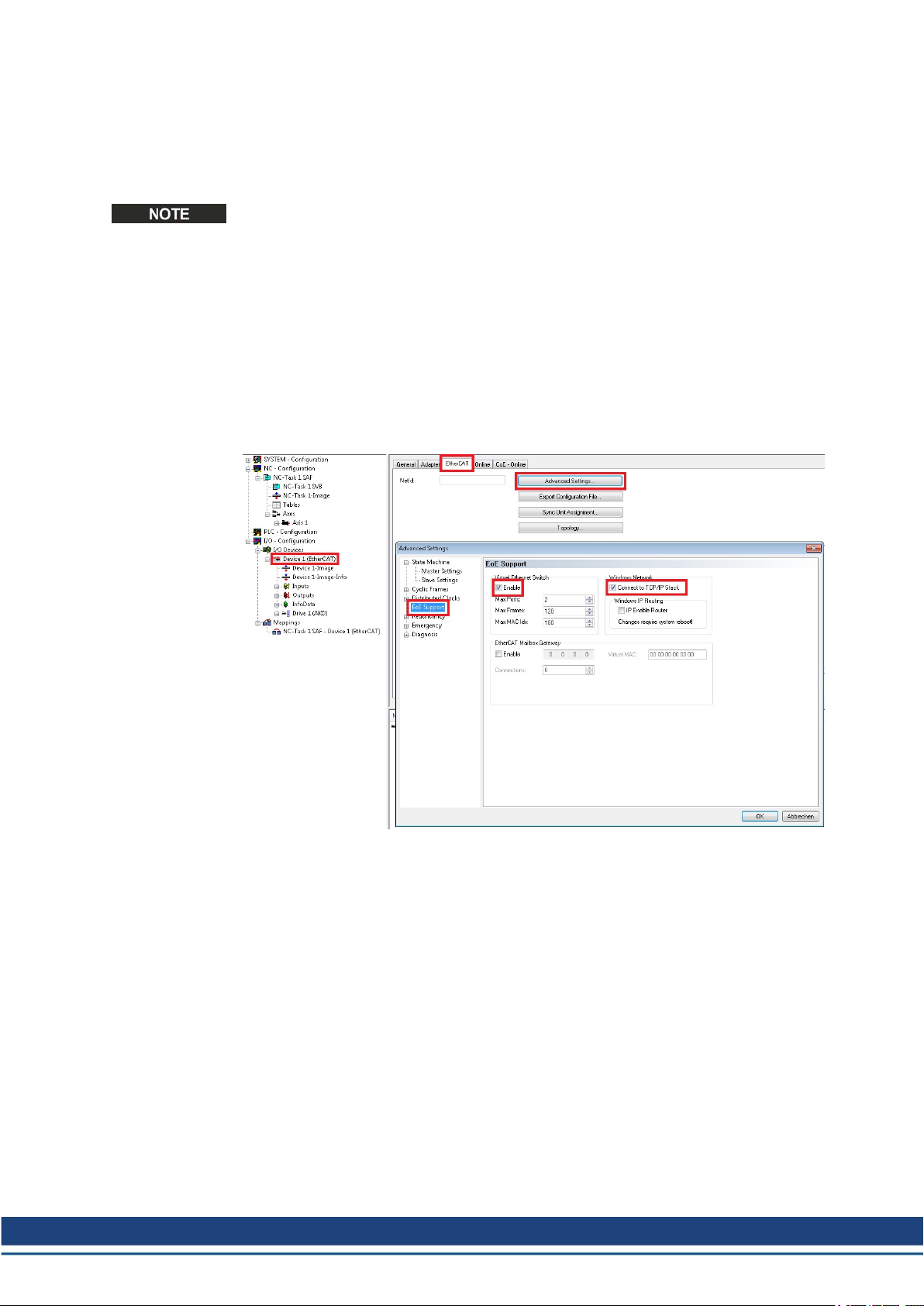
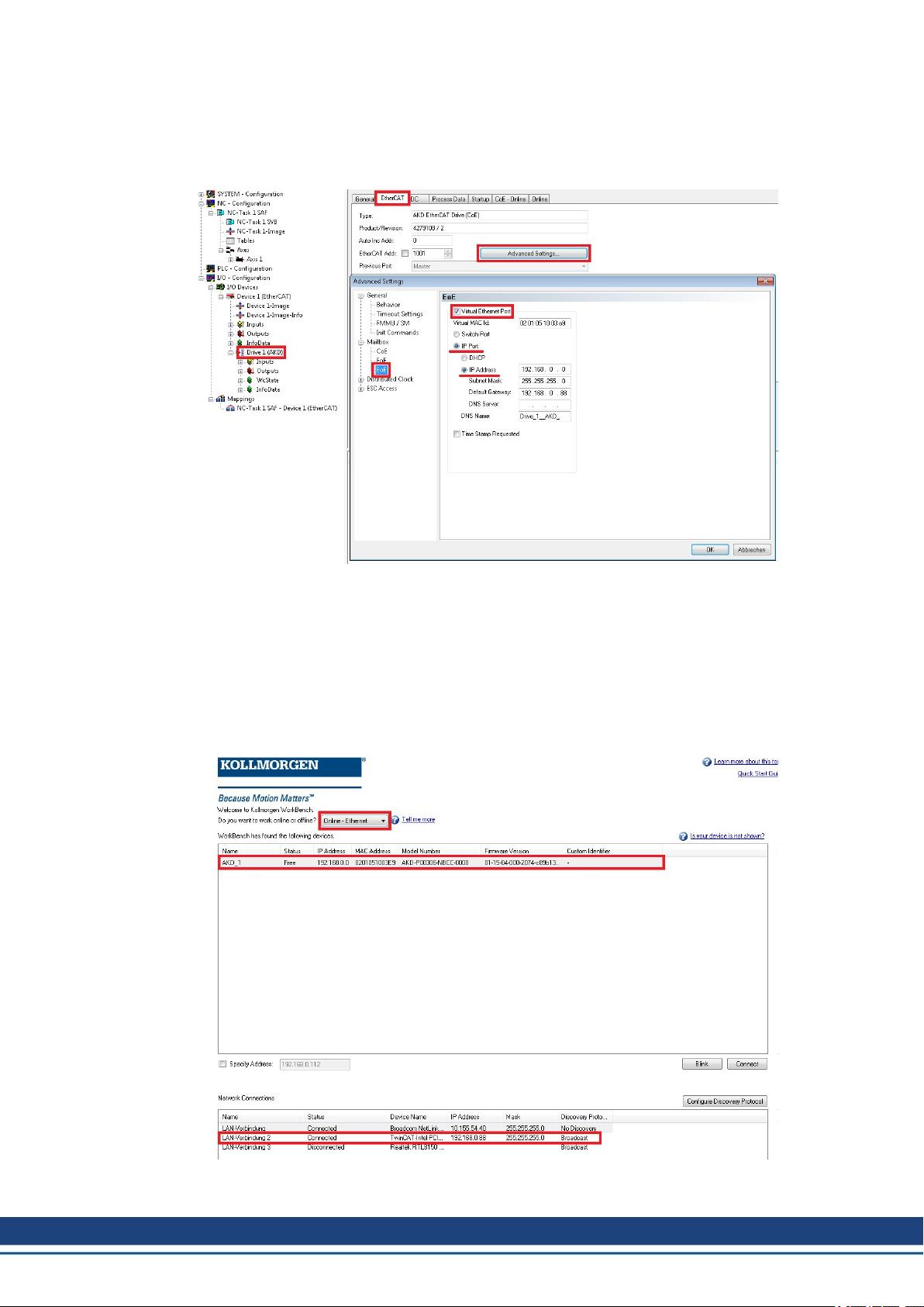
3.5.1 EtherCATDevice Settings
The first step is to make sure your EtherCAT device has EoE enabled. TwinCAT has a dedicated “EoE Support” page inside the EtherCAT device’s settings.
Enable "Virtual Ethernet Switch." Check the box "Connect to TCP/IP Stack."
AKD-C/N EtherCAT | 3 Installation and Setup
Kollmorgen | kdn.kollmorgen.com | October 2020 19
Page 20
AKD-C/N EtherCAT | 3 Installation and Setup
3.5.2 Drive Settings
After setting up the EtherCAT device, you must enable EoE for the drive. In TwinCAT there
is an EoE page within the Drive’s Mailbox settings. If the EoE page is not displayed, add the
drive to the EtherCAT network again, using the latest device description.
To enable EoE on your drive, check the “Virtual Ethernet Port” box, select “IP Port” and “IP
Address and enter at least a valid IP address and subnet mask.
3.5.3 Connecting to the Drive
You should now be able to access your drive over WorkBench using EoE.
Open WorkBench and make sure the discovery protocol is enabled for the network interface
that is in the subnet configured for your drive in the previous step. You can now connect to
your drive as if it were connected over the service port.
20 Kollmorgen | kdn.kollmorgen.com | October 2020
Page 21

3.5.4 Performance Concerns
Since EoE is very demanding on EtherCAT Mailbox communication, all measures to improve
Mailbox performance should be taken.
When releasing the EoE feature, the biggest allowed mailbox size has been increased from
512 to 1024 byte. A larger mailbox means fewer Mailbox transfers, resulting in a performance
increase.
Furthermore an additional Fieldbus Memory Management Unit (FMMU) has been added. This
allows the master to be notified of new data in the mailbox input without the need to poll the
mailbox, leading to a decrease in reaction time, thus improving performance. If your master
does not support this, you should at least try to decrease the period in which the master polls
the drive’s mailbox.
3.5.5 Restrictions
l Since a firmware download restarts the drive in the resident firmware, which does not sup-
port Ethernet over EtherCAT, downloading firmware via EoE is not possible. To update
your drive’s firmware use FoE instead.
l If your EtherCAT master uses the device description provided in the esi-file and you want
to automatically detect your drives, set the keyword ECAT.LEGACYREV to 0. The drive
will then report a different revision number and will be recognized by the master as a
device capable of Ethernet over Ethercat.
AKD-C/N EtherCAT | 3 Installation and Setup
3.6 Setup via TwinCAT NC/PTP System Manager
Before you set up the drive, make sure the following have been completed:
The AKD is configured with WorkBench and the servomotor is able to move
A correctly configured EtherCAT card is present in the master.
TwinCAT software from Beckhoff (NC/PTP-Mode setup) is installed. Install first the
TwinCAT System Manager, restart your PC, then install the option package NC/PTPMode.
The XML description of the drive is available (the XML file on the DVD or on the Kollmorgen website).
An AKD EtherCAT slave is connected to the EtherCAT master PC.
The TwinCAT system manager resides in Config-Mode. The current mode of the system
manager is displayed of the bottom right side of the TwinCAT main-screen window.
Copy the XML description of the drive to the TwinCAT system (usually to the folder
c:\TwinCAT\IO\EtherCAT) and restart the TwinCAT system since TwinCAT analyzes all
device description files during start-up.
The following example explains the automatic EtherCAT network setup. The network setup
can also be done manually; please refer to the TwinCAT manual for more details.
Kollmorgen | kdn.kollmorgen.com | October 2020 21
Page 22
AKD-C/N EtherCAT | 3 Installation and Setup
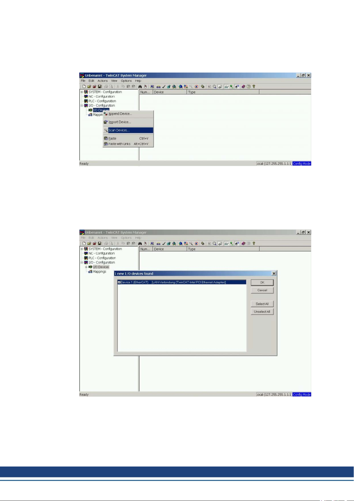
3.6.1 Scan devices
First ensure that the EtherCAT master is physically connected to the EtherCAT AKD. Create
a new (empty) project. Right click I/O Devices and scan for the devices. An example is
included in the EtherCAT network card, which is plugged into the PC.
A pop-up window informs you that not all devices can be detected by the TwinCAT software.
Click OK to continue.
3.6.2 Select the device
TwinCAT must be able to find the EtherCAT network card. An EtherCAT slave must be connected to the network card; otherwise TwinCAT will find a real-time EtherNET card instead of
the EtherCAT card. Press the OK button.
22 Kollmorgen | kdn.kollmorgen.com | October 2020
Page 23
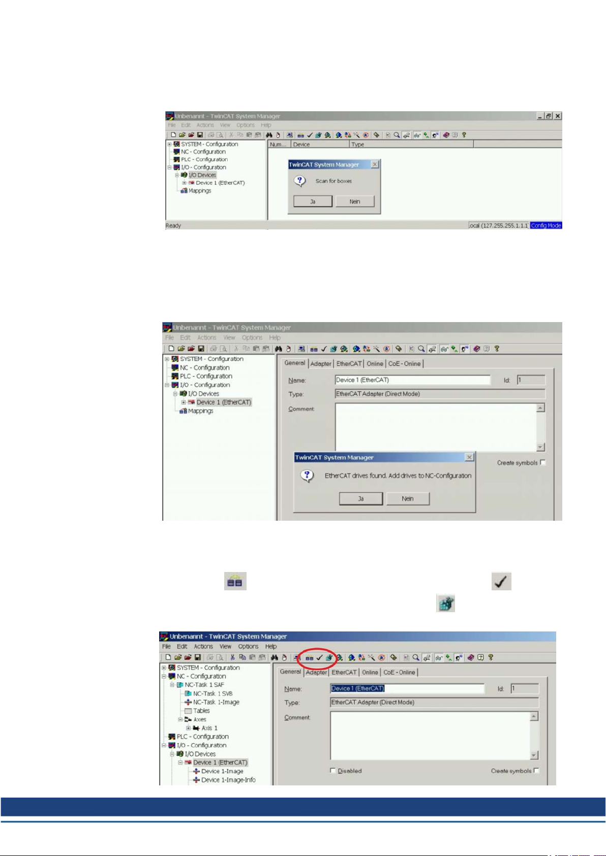
3.6.3 Scan for boxes
Click Yes to allow TwinCat to scan for boxes. A box is an alias for a slave device and is
always used in Beckhoff software products.
3.6.4 Add Slaves to NC tasks
TwinCAT should now have identified the AKD according to the Device Description file.
TwinCAT next asks if the slaves should be connected to NC tasks. Click Yes to continue.
An NC task can, for example, contain a PLC program, which can be programmed by the
user.
AKD-C/N EtherCAT | 3 Installation and Setup
3.6.5 Enable the network configuration
Confirm that the AKD appears in the device tree. Next, enable the network configuration.
First press the button in order to generate the mappings, then press the button in
order to let TwinCAT check the configuration and use finally the button in order to step
into run-mode. Confirm afterwards that TwinCAT is allowed to jump into run-mode.
Kollmorgen | kdn.kollmorgen.com | October 2020 23
Page 24
AKD-C/N EtherCAT | 3 Installation and Setup
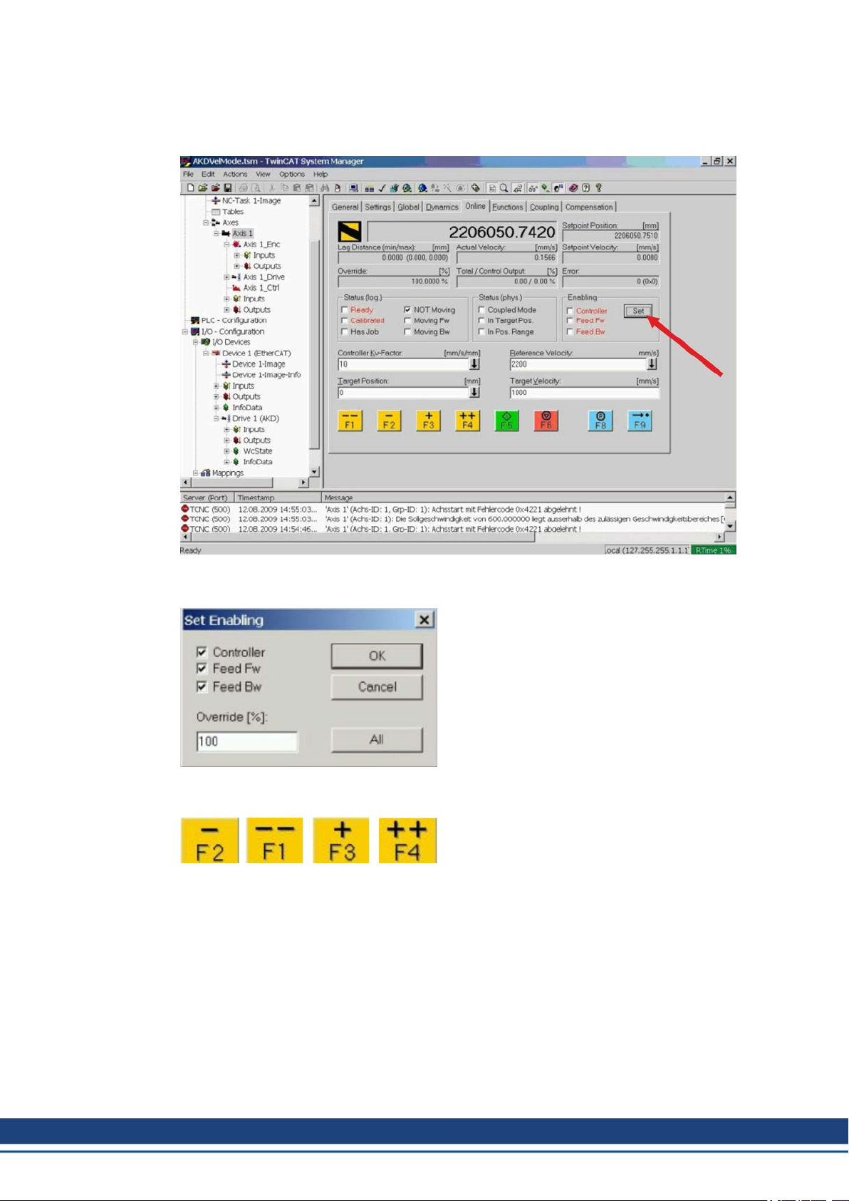
3.6.6 Enable the axis and move the axis
The Axis can be enabled by a mouse-click on the Set button within the Online window inside
of each Axis, see also the next picture.
Afterwards a pop-up window appears.
The following setting enables the drive and allows command values in both directions.
Afterwards the motor should move in positive or negative direction as soon as the clicks on
the following yellow buttons within the Online window:
24 Kollmorgen | kdn.kollmorgen.com | October 2020
Page 25
3.7 Setup WorkBench over TwinCAT
This chapter describes a quick start guide to setup a WorkBench over TwinCAT system and
make a motor spin under that system.
This chapter does not give specific details on TwinCAT system or WorkBench alone but is
giving guidelines and information on how TwinCAT master and WorkBench works together.
Main steps in configuring a WorkBench over TwinCAT system are:
TwinCAT and WorkBench configuration
Connecting to a drive using WorkBench
Configuring and enabling a drive
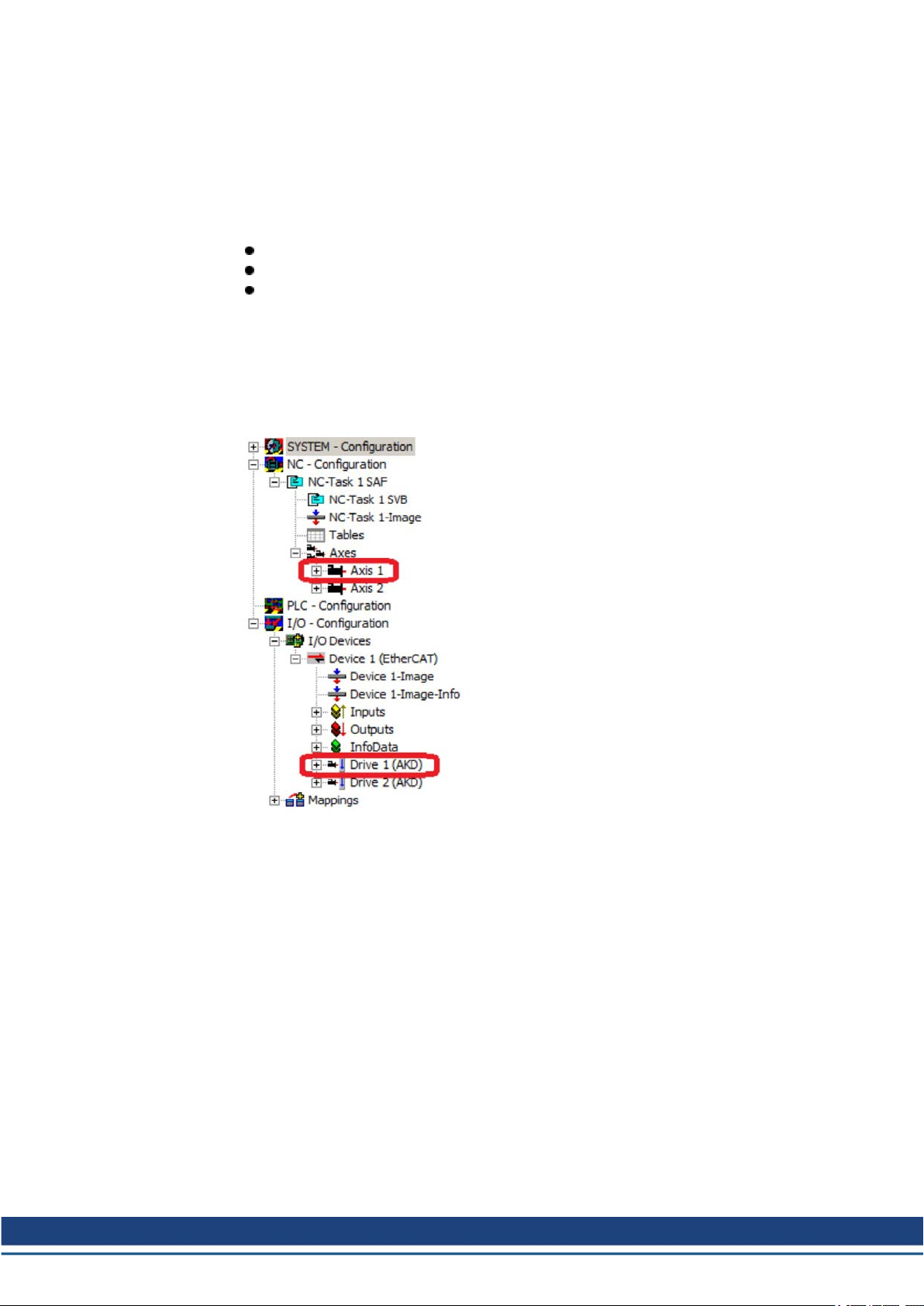
3.7.1 TwinCAT and WorkBench Configuration
The EtherCAT network must be setup and managed using TwinCAT System Manager. To be
able to connect to a drive and enable it, the drive must be loaded under the I/O Devices node
in TwinCAT System Manager and axis must be added to NC - Configuration as shown ➜ p.
21 "Setup via TwinCATNC/PTPSystem Manager " in the EtherCATManual.
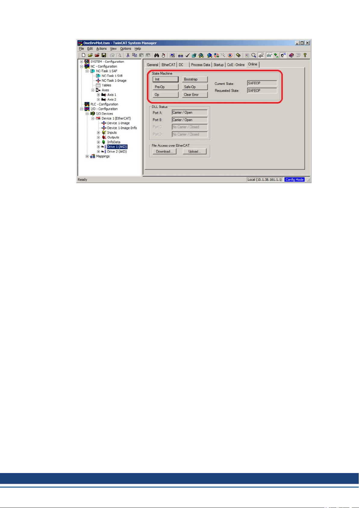
AKD-C/N EtherCAT | 3 Installation and Setup
In order to connect to the drives using WorkBench, the drives must be either in Pre-Op, SafeOp or Op state. State machine for a drive can be accessed from the Online tab for the corresponding drive under the I/O Configuration → I/O Devices → Device [x] → Drive [x] node
(see screenshot below).
Kollmorgen | kdn.kollmorgen.com | October 2020 25
Page 26
AKD-C/N EtherCAT | 3 Installation and Setup
Installation process for WorkBench is the same process as normal, except that it must be
installed on the same machine as TwinCAT. Communication to the drive is done thru
TwinCAT master and it's not possible to connect WorkBench to the master remotely.
26 Kollmorgen | kdn.kollmorgen.com | October 2020
Page 27
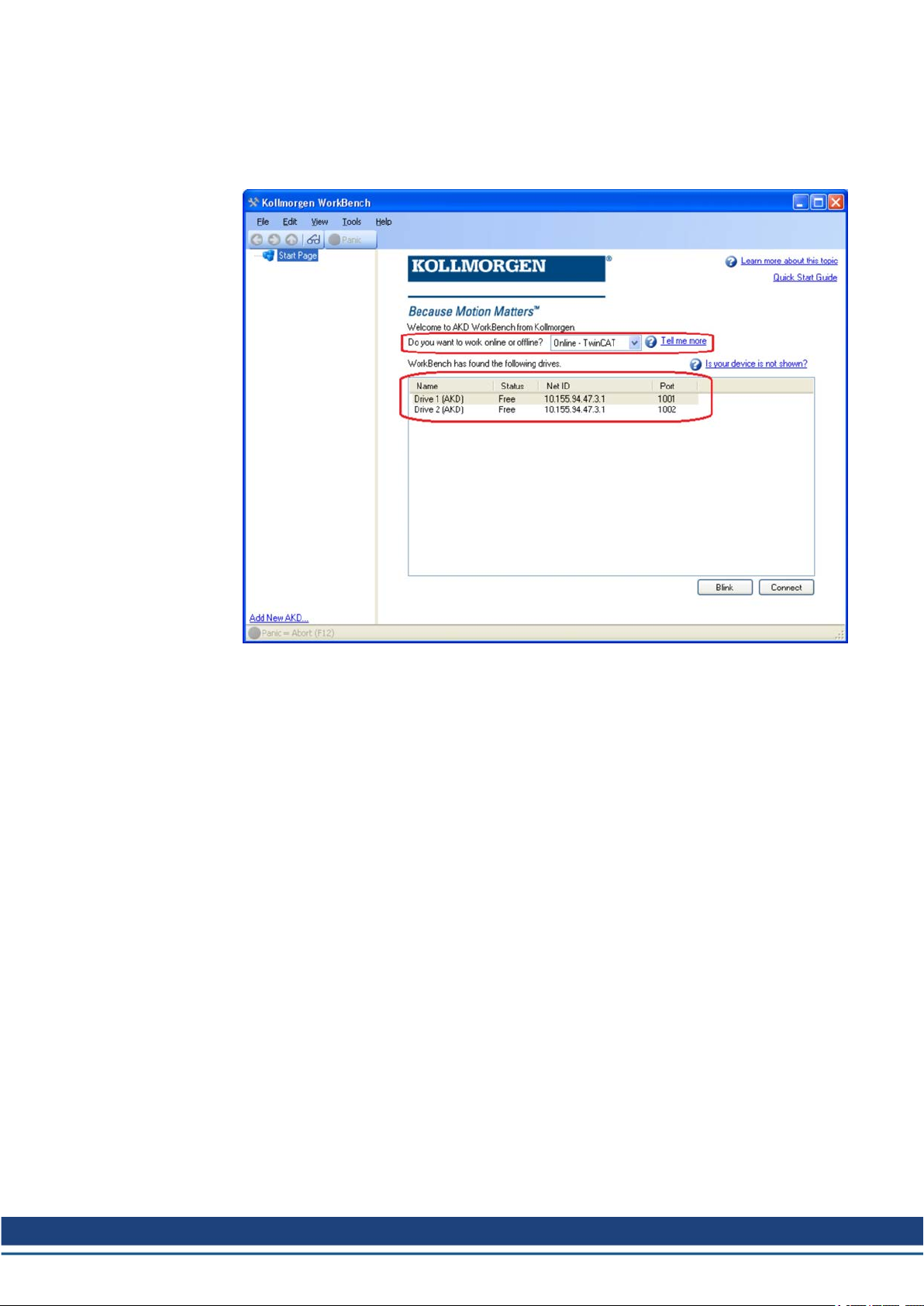
3.7.2 Connecting to a Drive Using WorkBench
In order to connect to a drive, a TwinCAT device must be added in WorkBench. The start
page of WorkBench can be used to do this. First, the type of drive (Online - TwinCAT) must
be specified. Then, a list of available drives will be provided.
AKD-C/N EtherCAT | 3 Installation and Setup
The information provided for a drive are it's name, status, Net ID and Port number. After
selecting a drive from the list, clicking on the "Connect" button will create a device in the left
frame of WorkBenchand connect the device.
Kollmorgen | kdn.kollmorgen.com | October 2020 27
Page 28
AKD-C/N EtherCAT | 3 Installation and Setup
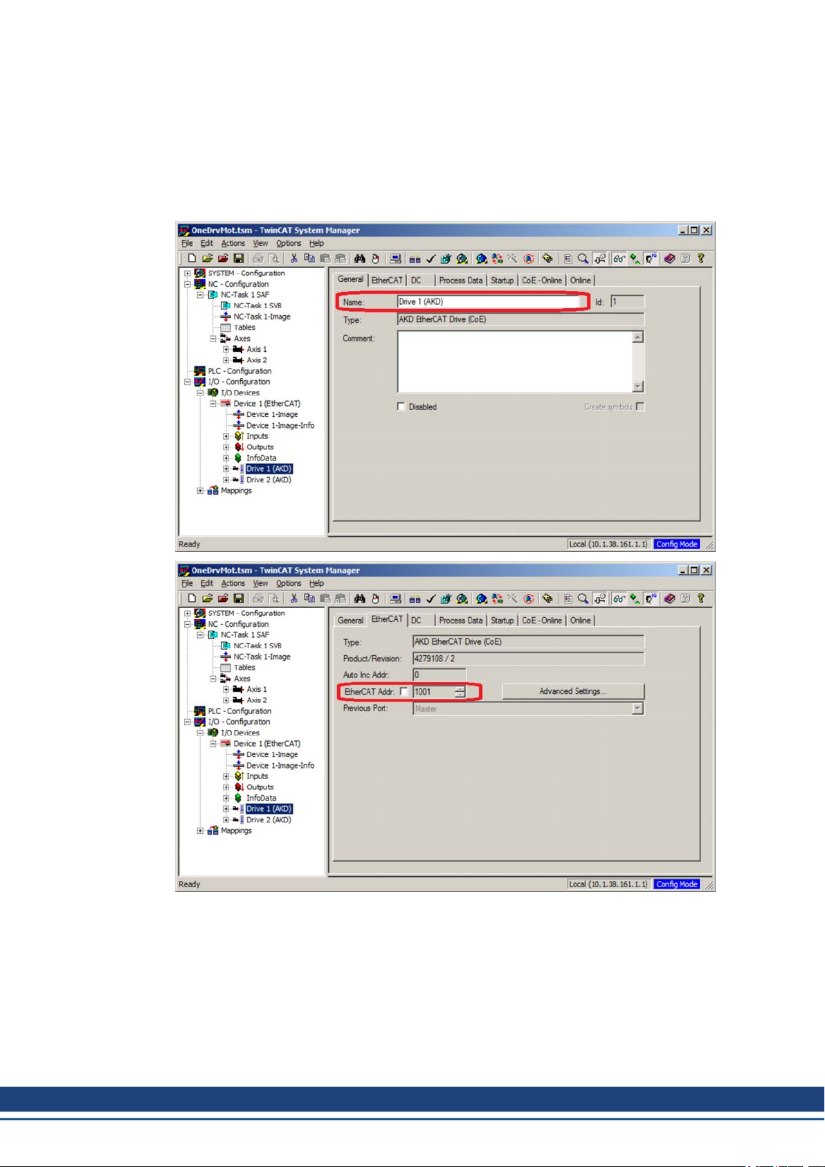
The name, Net ID and port number are information comming from the TwinCAT master configuration file (the name may be different than the drive name returned by the DRV.NAME
command). While the status is an indicator that tells if there is already a device created within
WorkBench which is already connected to that particular drive.
Using TwinCAT System Manager, the drive name and port number can be found in the General and EtherCAT tab respectively for the corresponding drive under the I/O Configuration →
I/O Devices → Device [x] → Drive [x] node.
28 Kollmorgen | kdn.kollmorgen.com | October 2020
Page 29
AKD-C/N EtherCAT | 3 Installation and Setup
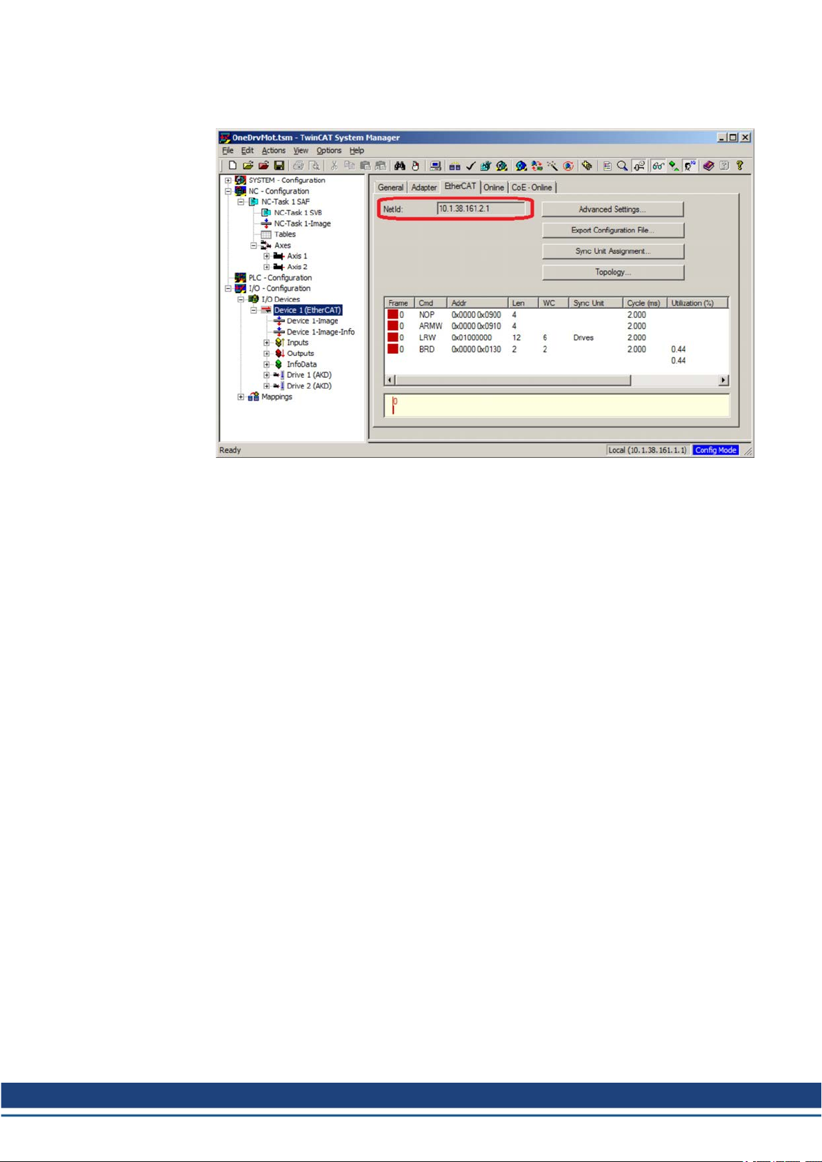
The Net ID can be found in the EtherCAT tab in the I/O Configuration → I/O Devices →
Device [x] node.
It is important to understand that thid information is coming from the TwinCAT master and it's
configuration file but not from the drive itself. Thus, if the TwinCAT configuration is not reflecting the actual network configuration, you may have a drive listed in WorkBench which is not
be powered up or even connected in the EtherCAT network, or you have a drive powered up
and connected to the TwinCAT network but not shown in the WorkBench list.
Kollmorgen | kdn.kollmorgen.com | October 2020 29
Page 30
AKD-C/N EtherCAT | 3 Installation and Setup
3.7.3 Configuring and Enabling a Drive
Once connected with WorkBench, a drive can be configured using all normal functionality of
WorkBench.
The only operation that is not possible to do using WorkBench over TwinCAT is the download
of a new firmware in the drive. Downloading a new firmware in the drive must be performed
using File over EtherCAT (FoE) feature of TwinCAT server.
If the cyclic communication of the TwinCAT master is enabled, it is possible that some commands sent by WorkBench using the ASCII channel are overwritten by the TwinCAT master.
Typically, the drive enable command will have no effect if sent from WorkBench because the
control word is usually mapped.
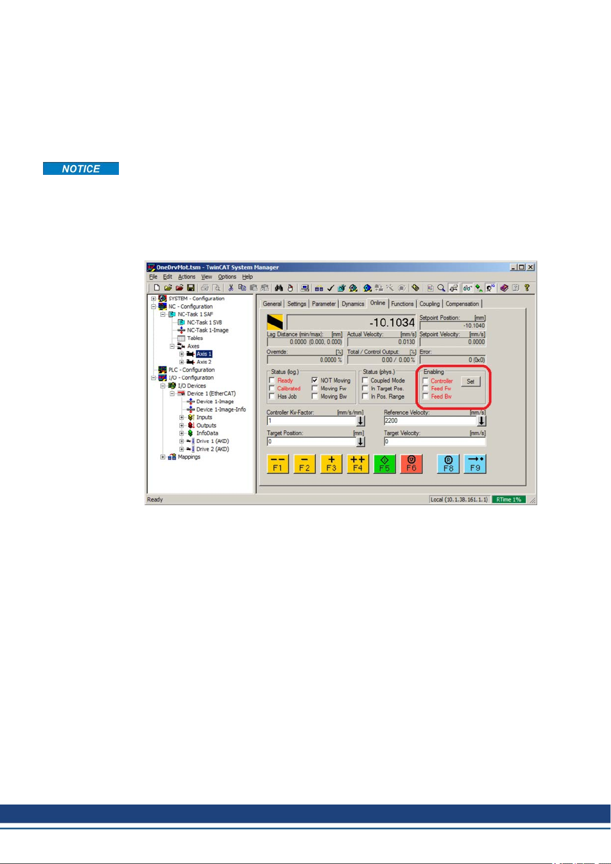
Using TwinCAT, enabling the drive can be done with the following procedure:
1. Under NC Configuration → Axes → Axis [x] node, choose the Online tab.
2. Press the Set button within the Enabling section.
3. In the pop-up dialog box, check the Controller checkbox to enable the drive (or un-check
to disable the drive) and press on the OK button.
30 Kollmorgen | kdn.kollmorgen.com | October 2020
Page 31

3.7.4 Download a Parameter File over TwinCAT
You can download a parameter file to the drive over EtherCAT. Before you start, make sure
that the drive is in INIT, PREOP, or SAFEOP state before trying to download the file.
1. First select the drive where you want to perform the download.
2. Change to the Online tab.
AKD-C/N EtherCAT | 3 Installation and Setup
3. Press the Download button.
4. Choose “All Files (*.*)” as file type to see the parameter files ending with “.akd”.
5. Select the file.
6. Press Open to start the download.
Downloading a parameter file over TwinCAT is supported by all drives from firmware
01.12.000.
Kollmorgen | kdn.kollmorgen.com | October 2020 31
Page 32

AKD-C/N EtherCAT | 3 Installation and Setup
3.8 Setup via KAS IDE
If you are using a Kollmorgen Automation Suite (KAS) system, the AKD setup is completely
integrated into the KAS Integrated Development Environment (IDE), as shown below:
For further information on the setup for a KASsystem, see the following sections in the KAS
documentation:
KAS IDE User Manual:See section 4.2.3 Add and Configure Drive.
KAS Online Help: See Using the KAS IDE> Creating a Project> Step 3 - Add and
Configure Drive.
32 Kollmorgen | kdn.kollmorgen.com | October 2020
Page 33

AKD-C/N EtherCAT | 4 EtherCAT Profile
4 EtherCAT Profile
4.1 Slave Register 34
4.2 AL Event (Interrupt Event) and Interrupt Enable 35
4.3 Phase Run-Up 37
4.4 CANopen over EtherCAT (CoE) State Machine 39
4.5 Fixed PDO Mappings 41
4.6 Flexible PDO Mappings 44
4.7 Supported Cyclical Setpoint and Actual Values 51
4.8 Supported Operation Modes 54
4.9 Adjusting EtherCAT Cycle Time 54
4.10 Maximum Cycle Times depending on operation mode 54
4.11 Synchronization 55
4.12 Latch Control Word and Latch Status Word 56
4.13 Mailbox Handling 57
4.14 EEProm Content 61
Kollmorgen | kdn.kollmorgen.com | October 2020 33
Page 34

AKD-C/N EtherCAT | 4 EtherCAT Profile
4.1 Slave Register
The table below gives the addresses of individual registers in the FPGA memory. The data is
provided in little-endian format, with the ’least significant byte’ occupying the lowest address.
A detailed description of all registers and FPGA memory locations is available in the “EtherCAT Slave Controller” description of the EtherCAT user organization (www.EtherCAT.org).
Address
0x0120 2 AL Control R/W R/O
0x0130 2 AL Status R/O R/W
0x0134 2 AL Status Code R/O R/W
0x0204 2 Interrupt Enable Register R/O R/W
0x0220 2 AL Event (IRQ Event) R/W R/O
0x0800 8 Sync Manager 0 (Mail Out Control Register) R/W R/O
0x0808 8 Sync Manager 1 (Mail In Control Register) R/W R/O
0x0810 8 Sync Manager 2 (Process data Output Con-
0x0818 8 Sync Manager 3 (Process data Input Control
0x0820 8 Sync Manager 4 R/W R/O
0x0828 8 Sync Manager 5 R/W R/O
0x0830 8 Sync Manager 6 R/W R/O
0x0838 8 Sync Manager 7 R/W R/O
0x0840 8 Sync Manager 8 R/W R/O
0x1100 Max. 64 ProOut Buffer (Process data Output, set-
0x1140 Max. 64 ProIn (Process data Input, act. values
0x1800 up to 512**
0x1C00 up to 512**
Length
(Byte)
up to 1024**
up to 1024**
Description
trol Register)
Register)
points ECAT)
ECAT)
Mail Out Buffer (Object Channel Buffer
ECAT, byte-length is specified in the device
description file)
Mail In Buffer (Object Channel Buffer Drive,
byte-length is specified in the device description file)
ZA
ECAT*ZADrive*
R/W R/O
R/W R/O
R/W R/O
R/O R/W
R/W R/O
R/O R/W
* ZA ECAT = Access mode EtherCAT
* ZA Drive = Access mode drive
** depends on firmware version and revision number
34 Kollmorgen | kdn.kollmorgen.com | October 2020
Page 35

4.2 AL Event (Interrupt Event) and Interrupt Enable
Communication between the drive and the EtherCAT FPGA can be interrupt-driven. The interrupt enable register and the AL event register are responsible for the EtherCAT interface interrupt functionality.
There are two events which lead also to a HW interrupt within the drive, the EEPROM emulation event and the SyncManager 2 event. The actual values of the drive (SyncManager 3
data) are written without any AL event request during each HW IRQ, e.g. triggered by a SyncManager 2 event. The Mailbox exchange between the master and the AKD is completely
handled by polling the AL event register within the background task of the drive.
The drive activates individual EtherCAT interface events when the corresponding bit of the
interrupt enable register is set to 1. When it is set to 0, the hardware interrupts for the specific
events are deactivated.
4.2.1 Interrupt Enable Register (Address 0x0204:0x0205)
AKD-C/N EtherCAT | 4 EtherCAT Profile
Parameter Address Bit
AL Control Event 0x204 0 R/W R/O Activation of AL control event for
- 0x204 1 R/W R/O Reserved
Sync0 DC Distributed
Clock
Sync1 DC Distributed
Clock
SyncManager activation
register change
EEPROM emulation
event
- 0x204 3 to 7 R/W R/O Reserved
Sync Manager 0 Event
(Mail Out Event)
Sync Manager 1 Event
(Mail In Event)
Sync Manager 2 Event
(Pro Out Event)
Sync Manager 3 Event
(Pro In Event)
- 0x205 4 to 7 R/W R/O Reserved
0x204 2 R/W R/O Activation of distributed clock
0x204 3 R/W R/O Activation of distributed clock
0x204 4 R/W R/O Activation of ‘SyncManager activ-
0x204 5 R/W R/O Activation of the EEPROM emu-
0x205 0 R/W R/O Activation of output event mail-
0x205 1 R/W R/O Activation of input event mailbox
0x205 2 R/W R/O Activation of output event pro-
0x205 3 R/W R/O Activation of input event process
ZA
DriveZAECAT
Description
phase run-up
(DC) sync 0 interrupts for entire
communication
(DC) sync 1 interrupts for entire
communication
ation register change’ IRQ.
lation interrupts.
box (SDO, Sync Manager 0) for
object channel.
(SDO, Sync Manager 1) for
object channel.
cess data (PDO, card's cyclical
setpoints)
data (PDO, drive's cyclical
actual values)
Kollmorgen | kdn.kollmorgen.com | October 2020 35
Page 36

AKD-C/N EtherCAT | 4 EtherCAT Profile
4.2.2 AL Event Request (Address 0x0220:0x0221)
When the relevant bit of the AL event request register is set to 1, the EtherCAT interface tells
the drive which event it should process by the AKD.
Parameter Address Bit
AL Control Event 0x220 0 R/O R/W Processing of AL control event
Sync0 Distributed Clock
(DC) Event
Sync1 Distributed Clock
(DC) Event
SyncManager activation
register change
EEPROM emulation
event
- 0x220 6 to 7 R/O R/W Reserved
Sync Manager 0 Event 0x221 0 R/O R/W Mailbox request (SDO, Sync
Sync Manager 1 Event 0x221 1 R/O R/W Mailbox response (SDO, Sync
Sync Manager 2 Event 0x201 2 R/O R/W Process data output (PDO,
Sync Manager 3 Event 0x201 3 R/O R/W Process data input (PDO,
Sync Manager 4 –
Sync Manager 7 Event 0x221 4 to 7 R/O R/W Reserved
Sync Manager 8 –
Sync Manager 15 Event 0x222 0 to 7 R/O R/W Reserved
0x220 2 R/O R/W Processing of a distributed
0x220 3 R/O R/W Processing of a distributed
0x220 4 R/O R/W The content of the Syn-
0x220 5 R/O R/W Processing of an EEPROM
ZA
DriveZAECAT
Description
for phase run-up
clock (DC) event
clock (DC) event
cManager activation register
has been changed.
emulation event in order to
identify the AKD within the network.
Manager 0) for object channel.
Manager 1) for object channel.
card's cyclical setpoints)
drive's cyclical actual values)
36 Kollmorgen | kdn.kollmorgen.com | October 2020
Page 37

4.3 Phase Run-Up
The AL control, AL status and AL status code registers are responsible for communication
phase run-up (also referred to as EtherCAT status change), for current status display and for
any fault messages. The drive responds to every EtherCAT interface transition request made
by the AL control register via the AL Status and AL Status Code registers. Any fault messages are displayed in the AL status code register.
A status change within the AL control register is polled within the AKD, which means that an
AL control event does not lead to a HW interrupt within the drive.
4.3.1 AL Control (Address 0x0120:0x0121)
AKD-C/N EtherCAT | 4 EtherCAT Profile
Parameter Address Bit
Status 0x120 3 to 0 R/O W/O 0x01: Init Request
0x02: PreOperational
Request
0x03: Bootstrap Mode
Request
0x04: Safe Operational
Request
0x08: Operational
Request
Acknowledgement 0x120 4 R/O W/O 0x00: No fault acknowledgement
Reserved 0x120 7 to 5 R/O W/O -
Applic. specific 0x120 15 to 8 R/O W/O -
4.3.2 AL Status (Address 0x0130:0x0131)
Parameter Address Bit
Status 0x130 3 to 0 W/O R/O 0x01: Init
0x02: PreOperational
0x03: Bootstrap Mode
0x04: Safe Operational
0x08: Operational
Status change 0x130 4 W/O R/O 0x00: Acknowledgement
Reserved 0x130 7 to 5 W/O R/O -
Applic. specific 0x130 15 to 8 W/O R/O -
ZA
DriveZAECAT
ZA
DriveZAECAT
Description
0x01: Fault acknowledgement
(positive edge)
Description
0x01: Error, e.g. forbidden transition
Kollmorgen | kdn.kollmorgen.com | October 2020 37
Page 38
AKD-C/N EtherCAT | 4 EtherCAT Profile
4.3.3 AL Status Code (Address 0x0134:0x0135)
Parameter Address Bit ZA Drive ZA ECAT Description
Status 0x134 7 to 0 W/O R/O See table below
Status 0x135 7 to 0 W/O R/O See table below
Code Description
0x0000 No error All Current Status
0x0011 Invalid requested state change I -> S, I -> O, P -> O,
0x0017 Invalid sync manager configuration I -> P, P -> S Current Status + E
No other codes are supported.
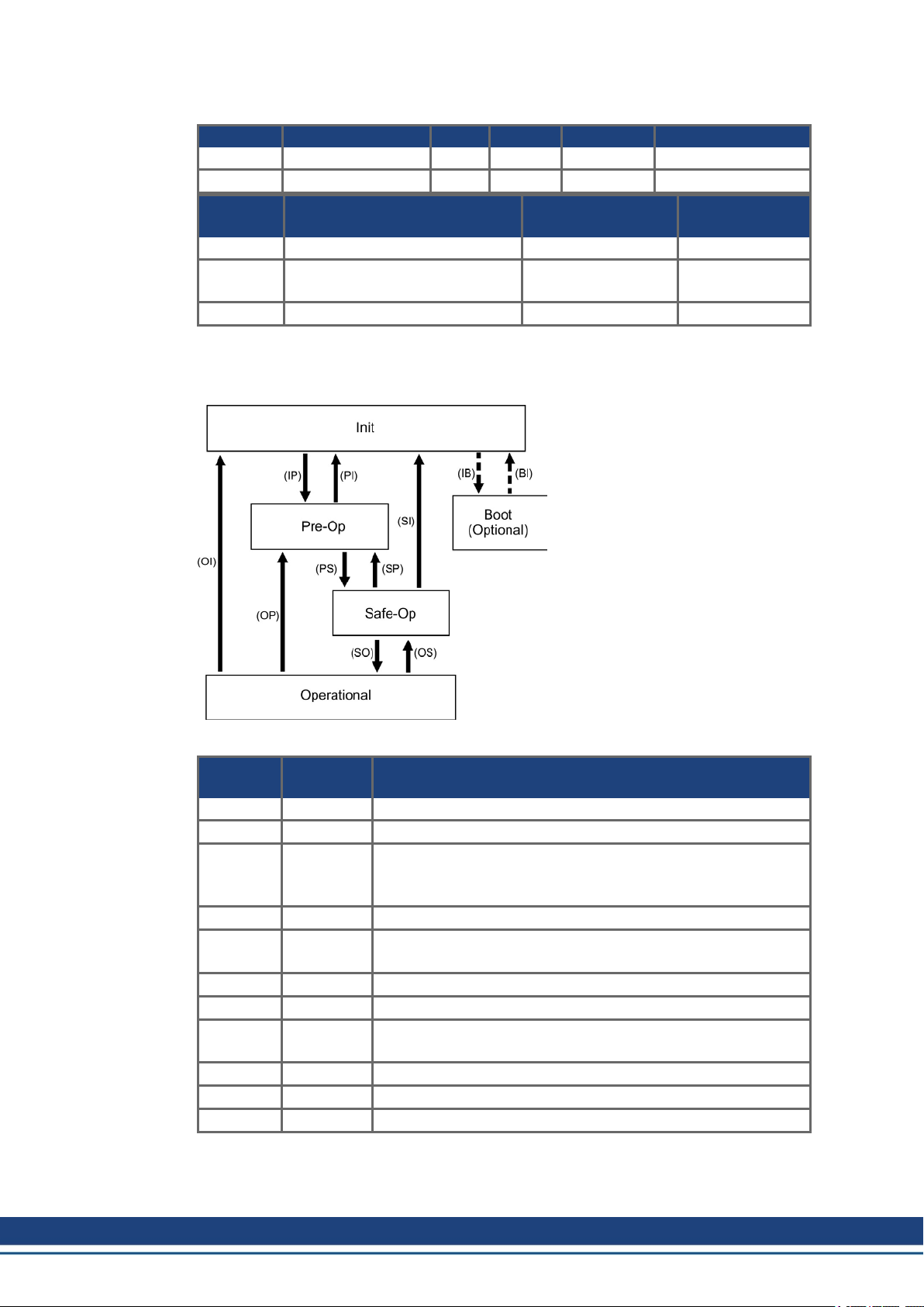
4.3.4 EtherCAT communication phases
Current Status
(Status change)
O -> B, S -> B, P -> B
INIT:
Initialization, no communication.
EEPROM emulation will be activated.
PRE-OP:
Mailbox active, slave parameterization
and startup parameters
Resulting Status
Current Status + E
SAVE-OP:
Cyclical actual values are transferred
and the drive tries to synchronize.
OPERATIONAL:
Cyclical setpoints are processed,
torque enable can be activated and the
drive must be synchronized.
Individual communication transitions
Transition
(IB) 0x03 -
(BI) - -
(IP) 0x02 AKD reads the SyncManager 0 & 1 configuration and verifies the
(PI) 0x01 -
(PS) 0x04 AKD reads the SyncManager 2 & 3 configuration and verifies the
(SP) 0x02 -
(SI) 0x01 -
(SO) 0x08 The SnycManager 2 hardware interrupt will be enabled by the
(OS) 0x04 Deactivation of SyncManager 2 hardware interrupt.
(OP) 0x02 Deactivation of SyncManager 2 hardware interrupt..
(OI) 0x01 Deactivation of SyncManager 2 hardware interrupt.
ALControl
(Bit 3 to 0)
Description
value of the start-address and the length. The AKD prepares
itself for handling SyncManager 0 events.
value of the start-address and the length.
drive.
38 Kollmorgen | kdn.kollmorgen.com | October 2020
Page 39

4.4 CANopen over EtherCAT (CoE) State Machine
AKD-C/N EtherCAT | 4 EtherCAT Profile
The state machine for the control and
status words corresponds to the
CANopen state machine in accordance
with DS402.
CANopen control and status words are
captured in every instance of fixed PDO
mapping (see chapter "Fixed PDO Mappings" (➜ p. 41)).
4.4.1 Status Description
Status Description
Not Ready to SwitchOnThe drive is not ready to switch on; the controller has not indicated
Switch On Disable In 'Switch On Disable' status, the amplifier cannot be enabled via
Ready to Switch On In 'Ready to Switch On' status, the drive can be enabled via the con-
Switched On In 'Switched On' status, the amplifier is enabled, but the setpoints of
Operation Enable In this status, the drive is enabled and setpoints are transferred from
Quick Stop Active The drive follows a quick stop ramp.
Fault Reaction Active The drive responds to a fault with an emergency stop ramp.
Fault A fault is pending, the drive is stopped and disabled.
readiness for service. The drive is still in the boot phase or in fault
status.
the EtherCAT interface, because (for example) there is no connection to a power source.
trol word.
the EtherCAT-interface are not yet transferred. The amplifier is idle,
and a positive edge in bit 3 of the control word activates setpoint
transfer (transition to 'Operation Enable' status).
the EtherCAT interface.
Kollmorgen | kdn.kollmorgen.com | October 2020 39
Page 40

AKD-C/N EtherCAT | 4 EtherCAT Profile
4.4.2 Commands in the Control Word
Bit assignment in the control word
Bit Name Bit Name
0 Switch on 8 Pause/halt
1 Disable Voltage 9 reserved
2 Quick Stop 10 reserved
3 Enable Operation 11 reserved
4 Operation mode specific 12 reserved
5 Operation mode specific 13 Manufacturer-specific
6 Operation mode specific 14 Manufacturer-specific
7 Reset Fault (only effective for faults) 15 Manufacturer-specific
Commands in the control word
Bit 7
Command
Shutdown X X 1 1 0 2, 6, 8
Switch on X X 1 1 1 3
Disable Voltage X X X 0 X 7, 9, 10, 12
Quick Stop X X 0 1 X 7, 10, 11
Disable Operation X 0 1 1 1 5
Enable Operation X 1 1 1 1 4, 16
Fault Reset 1 X X X X 15
Bits labeled X are irrelevant. 0 and 1 indicate the status of individual bits.
Mode-dependent bits in the control word
The following table shows the mode-dependent bits in the control word. Only manufacturerspecific modes are supported at present. The individual modes are set by Object 6060h
Modes of operation.
Operation mode No Bit 4 Bit 5 Bit 6
Profile Position Mode (pp) 01h new_setpoint change_set_
Profile Velocity Mode (pv) 03h reserved reserved reserved
Profile Torque Mode (tq) 04h reserved reserved reserved
Homing Mode (hm) 06h homing_operation_
Interpolated Position Mode (ip) 07h reserved reserved
Cyclic synchronous position
mode
Fault
Reset
Bit 3
Enable Oper-
ation
start
08h reserved reserved reserved
Bit 2
Quick
Stop
Bit 1
Disable
Voltage
immediately
reserved reserved
Bit 0
SwitchOnTransitions
absolute/relative
Description of the remaining bits in the control word
Bit 8: (Pause) If Bit 8 is set, then the drive halts (pauses) in all modes. The setpoints (speed
for homing or jogging, motion task number, setpoints for digital mode) for the individual
modes are retained.
Bit 9,10: These bits are reserved for the drive profile (DS402).
Bit 13, 14, 15: These bits are manufacturer-specific, and reserved at present.
40 Kollmorgen | kdn.kollmorgen.com | October 2020
Page 41

4.4.3 State Machine Bits (status word)
Bit assignment in the status word
Bit Name Bit Name
0 Ready to switch on 8 Manufacturer-specific (reserved)
1 Switched on 9 Remote (always 1)
2 Operation enable 10 Target reached
3 Fault 11 Internal limit active
4 Voltage enabled 12 Operation mode specific (reserved)
5 Quick stop 13 Operation mode specific (reserved)
6 Switch on disabled 14 Manufacturer-specific (reserved)
7 Warning 15 Manufacturer-specific (reserved)
States of the state machine
AKD-C/N EtherCAT | 4 EtherCAT Profile
Bit 6
State
Not ready to switch on 0 X 0 0 0 0
Switch on disabled 1 X 0 0 0 0
Ready to switch on 0 1 0 0 0 1
Switched on 0 1 0 0 1 1
Operation enabled 0 1 0 1 1 1
Fault 0 X 1 0 0 0
Fault reaction active 0 X 1 1 1 1
Quick stop active 0 0 0 1 1 1
Bits labeled X are irrelevant. 0 and 1 indicate the status of individual bits.
Description of the remaining bits in the status word
Bit 4: voltage_enabled The DC-link voltage is present if this bit is set.
Bit 7: warning There are several possible reasons for Bit 7 being set and this warning being
produced. The reason for this warning can be revealed by using the Object 2000h (system
warnings).
Bit 9: remote is always set to 1, i.e. the drive can always communicate and be influenced via
the RS232 - interface.
Bit 10: target_reached This is set when the drive has reached the target position.
Bit 11: internal_limit_active This bit specifies that a movement was or is limited. In different
modes, different warnings cause the bit to be set.
switch on
disable
Bit 5
quick
stop
Bit 3
fault
Bit 2
operation
enable
Bit 1
switched
on
Bit 0
ready to
switch
on
4.5 Fixed PDO Mappings
Various ready-to-use mappings can be selected for cyclic data exchange via SDO’s of the
object 0x1C12 and 0x1C13. Using object 0x1C12 subindex 1 (Sync Manager 2 assignment),
a fixed mapping for the cyclic command values can be set with the values 0x1701,
0x1702,0x1720 to 0x1725. Using object 0x1C13 subindex 1 (Sync Manager 3 assignment), a
fixed mapping for the cyclic actual values can be set via the data 0x1B01, 0x1B20 to
0x1B26.
Use the sequence below to select the fixed command value mapping 0x1701 via SDO’s:
1. SDO write access to object 0x1C12Sub0 Data:0x00
2. SDO write access to object 0x1C12Sub1 Data:0x1701
3. SDO write access to object 0x1C12Sub0 Data:0x01
Kollmorgen | kdn.kollmorgen.com | October 2020 41
Page 42

AKD-C/N EtherCAT | 4 EtherCAT Profile
Up to firmware version 1.8.x.x AKD.XML file, fixed mapping 0x1701 called out 0x6062sub0
as the “Position Command”. From AKD firmware release 1.8.5.0, the AKD.XML will be
changed to call out 0x60C1sub1 as the “Position Command” and an additional XML file called
“AKD_TwinCAT.XML” will be added to support TwinCat 2x and older. In reality, SDO
0x6062sub0 is not supported in the AKD firmware but was called in the fixed mapping to support a TwinCat issue.
Position interface, supported fixed mappings:
0x1701 Position command value (4 bytes), Control word (2 bytes), total (6 bytes)
0x1720 Control Word (2 bytes), Interpolated position command value (4 bytes), Latch
control word (2 bytes), Torque feed forward (2 bytes), Digital outputs (2 bytes)
0x1721 Interpolated position command value (4 bytes), Control Word (2 bytes), Torque
feed forward (2 bytes)
0x1722 Control word (2 byte), Interpolated position command value (4 bytes), Latch con-
trol word (2 bytes), Torque feed forward (2 bytes), Digital outputs (2 bytes), max.
torque (2 bytes)
0x1723 Control word (2 bytes), Interpolated position command value (4 bytes), Latch
control word (2 bytes), Torque feed forward (2 bytes), Digital outputs (2 bytes),
Reset of changed input information (2 bytes)
0x1724 Target position for cyclic synchronous position mode (4 bytes), Control word (2
byte), Torque feed forward (2 bytes)
0x1725 Controlword (2 bytes), Target position for cyclic synchronous position mode (4
bytes), Digital outputs (4 bytes), Torque feed forward (2 bytes), Analog output
value (2 bytes), Max torque (2 bytes)
0x1B01 Position actual value (4 bytes), Status word (2 bytes), total (6 bytes)
0x1B20 Position actual internal value (4 bytes), 2nd position feedback position (4 bytes),
velocity actual value (4 bytes), digital inputs (4 bytes), following error (4 bytes),
latch position positive (4 bytes), status word (2 bytes), torque actual value (2
bytes), latch status (2 bytes), analog input value (2 bytes)
0x1B21 Position Actual Internal Value (4 bytes), Status word (2 bytes)
0x1B22 Position actual internal value (4 bytes), 2nd position feedback position (4 bytes),
velocity actual value (4 bytes), digital inputs (4 bytes), following error (4 bytes),
latch position negative (4 bytes), status word (2 bytes), torque actual value (2
bytes), latch status (2 bytes), analog input value (2 bytes)
0x1B23 Position actual internal value (4 bytes), 2nd position feedback position (4 bytes),
velocity actual value (4 bytes), digital inputs (4 bytes), following error (4 bytes),
latch position positive / negative (4 bytes), status word (2 bytes), torque actual
value (2 bytes), latch status (2 bytes), analog input value (2 bytes)
0x1B24 Position actual value (4 bytes), status word (2 bytes)
0x1B25 Position actual internal value (4 bytes), 2nd position feedback position (4 bytes),
latch position 2 positive / negative (4 bytes), digital inputs (4 bytes), following
error (4 bytes), latch position 1 positive / negative (4 bytes), status word (2
bytes), torque actual value (2 bytes), latch status (2 bytes), analog input value (2
bytes)
0x1B26 Statusword (2 bytes), Position actual value (4 bytes), Analog input value (2
bytes), Digital inputs (4 bytes), Following error actual value (4 bytes)
42 Kollmorgen | kdn.kollmorgen.com | October 2020
Page 43

AKD-C/N EtherCAT | 4 EtherCAT Profile
Velocity interface, supported fixed mappings:
0x1702 Velocity command value (4 bytes), Control word (2 bytes), total (6 bytes)
The objects, which are mapped into the fixed PDOs can be read via the subindices 1 to n of
the above indices. The number of mapped entries is available by reading subindex 0 of the
above indices.
Example:
A read access to object 1702 sub 0 gives a value of 2, a read on subindex 1 gives
0x60ff0020, on subindex 2 0x60400010. The meaning of these numbers can be seen in the
CANopen manual or the flexible-mapping example (➜ p. 46.).
Kollmorgen | kdn.kollmorgen.com | October 2020 43
Page 44

AKD-C/N EtherCAT | 4 EtherCAT Profile
4.6 Flexible PDO Mappings
In addition to the fixed PDO mapping the so-called flexible mapping of real-time objects is
possible.
Available objects for PDO mapping are listed in the object dictionaries ("Appendix" (➜ p.
62)). All objects with the entry "yes" in column "PDO map." can be used.
Restrictions of flexible mapping:
l An odd length PDO is not allowed.
In the Rx(=set-point)-direction the dummy-object 0x0002 sub 0 with a length of 8 bits
can be used to make the PDO-length even.
In the Tx(=actual value)-direction one sub-index of the manufacturer status object
0x2002 sub 1..4 can be used to guarantee the even length of the Tx-PDO.
These special mappings may be used if the objects 0x6060 and 0x6061 have to be
used in the mapping.
l The allowed PDOs have up to 32 bytes (Tx), 20 bytes for RX (FW version < 1.16) or 20
bytes for RX(FW > = 1.17). They are built from smaller PDO modules with a maximum
length of 8 bytes. These are built by using the mapping objects 0x1600 to 0x1603 and
0x1a00 to 0x1a03.
The configuration is similar to the described sequence for the fixed mappings:
1. The mapping selection is cleared (write 0 to object 0x1C12 sub 0 and 1C13 sub 0)
2. As the AKD - implementation is based on CANopen the real-time data are build from up to
4 PDOs with 8 bytes in both directions. These PDOs are built in the same way as in a
CAN-drive with the objects 0x1600 - 0x1603 and 0x1A00 - 0x1A03. Unused PDOs must
be cleared with writing 0 to the subindex 0.
3. SDO write access to object 0x1C12 sub 1 .. 4 with the PDOs (0x1600 .. 0x1603), that
should be used in receive direction of the AKD (set point values).
4. SDO write access to object 0x1C13 sub 1 .. 4 with the PDOs (0x1A00 .. 0x1A03), that
should be used in transmit direction of the AKD (actual values).
5. SDO write access to the objects 0x1C12 sub 0 and 0x1C13 sub 0 with the number of
mapped PDOs in this direction.
See an example in chapter "Flexible PDO Mappings" (➜ p. 44) .
The cyclically used data are visible in the PDO-assignment window for the Inputs and Outputs of the Sync Managers. Default setting are the fixed PDOs 0x1701 and 0x1B01 (visible
contents when selected in the PDO list).
44 Kollmorgen | kdn.kollmorgen.com | October 2020
Page 45

AKD-C/N EtherCAT | 4 EtherCAT Profile
If the flexible mapping is required, the PDO configuration check box must be changed.
4.6.1 Example: Flexible PDO Mapping
For the flexible mapping of the Outputs the fixed mapping 0x1701 has to be switched off and
up to 4 free-mappable PDOs (0x1600-0x1603) can be used instead. The maximum number of
bytes for each of these PDOs is 8.
After that the default mapping of e.g. the PDO 0x1600 can be extended:
==========>
Kollmorgen | kdn.kollmorgen.com | October 2020 45
Page 46

AKD-C/N EtherCAT | 4 EtherCAT Profile
A list of possible objects for the mapping will be shown and a new entry can be chosen.
In this case the setpoint for the interpolated
position mode is selected.
The same is valid for the Tx-PDO-direction.
Here the value of the actual internal position
is selected.
This results in the startup-SDO-list for this sample free-mapped-configuration.
The meaning of the data (for example 0x60410010 in the mapping of 0x1A00 sub 1) is as follows:
0x6041 is the index of the DS402 status word
0x00 is the subindex of the DS402 status word
0x10 is the number of bits for this entry, i. e. 16 bits or 2 bytes.
46 Kollmorgen | kdn.kollmorgen.com | October 2020
Page 47

AKD-C/N EtherCAT | 4 EtherCAT Profile
If this shall be used in the NC, the interpolation set point position has to be linked from the
axis to the NC-axis.
Kollmorgen | kdn.kollmorgen.com | October 2020 47
Page 48

AKD-C/N EtherCAT | 4 EtherCAT Profile
After doing this configuration the mapping can be activated as seen before in this document:
Now the NC-screen should show a position in the online window, which changes a bit in the
last digits.
After enabling the power stage with the All-button, the drive can be moved via the jog-buttons
or via the functions in the function menu.
48 Kollmorgen | kdn.kollmorgen.com | October 2020
Page 49

AKD-C/N EtherCAT | 4 EtherCAT Profile
4.6.2 Example: Flexible PDOMapping with one byte gap in Rx-PDO
The AKD needs an even number of bytes in a PDO so it can be necessary to fill a gap if a one
byte object like object 6060h sub 0 (mode of operation) is mapped to the Rx-PDO. This can
be done in the following sequence:
Rx-PDO Mapping with Controlword and 1st set-point.
Insert a one byte gap.
Kollmorgen | kdn.kollmorgen.com | October 2020 49
Page 50

AKD-C/N EtherCAT | 4 EtherCAT Profile
In CANopen over EtherCAT, a gap is programmed using index 0 sub 0 with the size of the
gap with one byte in the example.
Insert additional object 6060h sub 0 (mode of operation).
Result:
50 Kollmorgen | kdn.kollmorgen.com | October 2020
Page 51

View in the TwinCat I/O display.
AKD-C/N EtherCAT | 4 EtherCAT Profile
For Tx-PDOs, an even number of bytes is required. To fill a gap in the Tx-PDO mapping,
existing one byte objects like 2002h sub 1 (Manufacturer status byte 1) can be used.
4.7 Supported Cyclical Setpoint and Actual Values
Supported cyclical setpoint values
Name
Target current 0x2071 sub 0 32 bit scaled in mA
Latch Control word 0x20A4 sub 0 UINT16
Clear digital Input Change Bit 0x20B8 16 bit
Analog output value 0x3470 sub 3 16 bit
External feedback position 0x3497 sub 0 32 bit
CANopen control-word 0x6040 sub 0 UINT16 CANopen control word.
Modes of Operation 0x6060 sub 0 8 bit DS402 opmode setpoint
Velocity Window 0x606D sub 0 16 bit
Velocity Window Time 0x606E sub 0 16 bit
Target Torque 0x6071 sub 0 16 bit 0.1% resolution
Maximum Torque 0x6072 sub 0 16 bit
CANopen
object
Data
type
Description
Kollmorgen | kdn.kollmorgen.com | October 2020 51
Page 52

AKD-C/N EtherCAT | 4 EtherCAT Profile
Name
CANopen
object
Data
type
Description
Target position 0x607A sub 0 INT32 Used in profile position mode / cyc-
lic synchronous position mode
Profile position target velocity 0x6081 sub 0 32 bit related to MT.V
Profile position target acc 0x6083 sub 0 32 bit related to MT.ACC
Profile position target dec 0x6084 sub 0 32 bit related to MT.DEC
Velocity feed forward 0x60B1 sub 0 32 bit
Torque feed forward 0x60B2 sub 0 INT16
Touch probe function 0x60B8 16 bit
Position command value 0x60C1 sub 1 INT32 Interpolation data record in IP-
mode
Digital outputs 0x60FE sub 1 UINT32
Velocity command value 0x60FF sub 0 INT32
52 Kollmorgen | kdn.kollmorgen.com | October 2020
Page 53

Supported cyclical actual values
AKD-C/N EtherCAT | 4 EtherCAT Profile
Name
CANopen
object
Data
type
Description
Position actual internal value 0x6063 sub 0 INT32
Velocity actual value 0x606C sub 0 INT32
CANopen status-word 0x6041 sub 0 UINT16 CANopen status word
Second position feedback 0x2050 sub 0 INT32
Digital inputs 0x60FD sub 0 UINT32
Following error actual value 0x60F4 sub 0 INT32
Latch position positive edge 0x20A0 sub 0 INT32
Torque actual value 0x6077 sub 0 INT16
Latch status 0x20A5 sub 0 UINT16
Actual Current 0x2077 sub 0 32 bit scaled in mA
Latch1 negative edge 0x20A1 sub 0 32 bit
Latch2 Positive 0x20A2 sub 0 32 bit
Latch2 Negative 0x20A3 sub 0 32 bit
Latch1 positive/negative edge 0x20A6 32 bit
Latch 2 positive/negative edge 0x20A7 32 bit
Modes of Operation 0x6061 8 bit DS402 opmode status
Position Actual Value 0x6064 sub 0 32 bit WB/ DS402 scale units
Touch probe status 0x60B9 sub 0 16 bit
Touch probe 1 positive edge pos 0x60BA sub 0 32 bit
Touch probe 1 negative edge pos 0x60BB sub 0 32 bit
Touch probe 2 positive edge pos 0x60BC sub 0 32 bit
Touch probe 2 negative edge pos 0x60BD sub 0 32 bit
Additional Pos actual value 0x60E4 sub 0 48 bit
Additional Pos actual value 0x60E4 sub 1 32 bit
Motor I2t 0x3427 sub 3 32 bit
Analog output value 0x3470 sub 2 16 bit
Analog Input value 0x3470 sub 4 16 bit
Manufacturer status register 0x1002 sub 0 32 bit
Kollmorgen | kdn.kollmorgen.com | October 2020 53
Page 54

AKD-C/N EtherCAT | 4 EtherCAT Profile
4.8 Supported Operation Modes
CANopen mode of
operation
Profile velocity DRV.OPMODE 1
Interpolated position DRV.OPMODE 2
Homing mode DRV.OPMODE 2
Profile Position DRV.OPMODE 2
Torque DRV.OPMODE 0
Cyclic Synchronous
Position
AKD mode of operation
DRV.CMDSOURCE 1
DRV.CMDSOURCE 1
DRV.CMDSOURCE 0
DRV.CMDSOURCE 0
DRV.CMDSOURCE 1
DRV.OPMODE 2
DRV.CMDSOURCE 1
Description
0x6060Sub0 Data: 3
In this mode, the EtherCAT master sends
cyclic velocity command values to the
AKD.
0x6060Sub0 Data: 7
In this mode of operation the EtherCAT master sends cyclic position command values
to the AKD. These command values are
interpolated by the AKD according to the
fieldbus sample rate.
0x6060 sub 0 data : 6
In this mode an AKD-internal homing can be
done.
0x6060sub0 Data: 1
Uses motion task 0 to execute a point to
point move
0x6060sub0 Data: 4
Commands torque in % of drive peak torque
0x6060sub0 Data: 8
Master calculates move profile and commands motion with position points
4.9 Adjusting EtherCAT Cycle Time
The cycle time to be used in the drive for the cyclical setpoints and actual values can either
be stored in the FBUS.SAMPLEPERIOD parameter in the amplifier or configured in the startup phase. This happens via SDO mailbox access to objects 60C2 subindex 1 and 2 for the
AKD-N. The setup for the AKD-C is done via Register writing to the appropriate ESC
registers 9A0h / 9A2h.
Subindex 2, known as the interpolation time index, defines the power of ten of the time value
(e.g. -3 means 10-3 or milliseconds) while subindex 1, known as interpolation time units,
gives the number of units (e.g. 4 means 4 units).
You can run a 2 ms cycle using various combinations. For example,
Index = -3, Units = 2 or
Index = -4, Units = 20 etc.
The FBUS.SAMPLEPERIOD parameter is counted in multiples of 62.5us microseconds
within the device. This means, for example that 2 ms equates to FBUS.SAMPLEPERIOD
value of 32.
4.10 Maximum Cycle Times depending on operation mode
The minimum cycle time for the drive is largely dependent on the drive configuration (second
actual position value encoder latch functionality enabled and so on)
Interface Cycle time AKD
Position ≥ 0.25 ms (≥ 250 µs)
Velocity ≥ 0.25 ms (≥ 250 µs)
Torque ≥ 0.25 ms (≥ 250 µs)
54 Kollmorgen | kdn.kollmorgen.com | October 2020
Page 55

AKD-C/N EtherCAT | 4 EtherCAT Profile
4.11 Synchronization
On all drives, the internal PLL is theoretically able to even out an average deviation of up to
4800 ppm in the cycle time provided by the master. The drive checks once per fieldbus cycle
a counter within the drive internal FPGA, which is cleared by a Sync0 (Distributed clock)
event. Depending of the counter value, the drive extends or decreases the 62.5 µs MTS signal within the drive by a maximum of 300 ns.
The theoretical maximum allowed deviation can be calculated by using the following formula:
The synchronization functionality within the drive can be enabled via setting bit 0 of the
FBUS.PARAM02 parameter to high. Therefore FBUS.PARAM02 must be set to the value of
1. Furthermore the distributed clock functionality must be enabled by the EtherCAT master in
order to activate cyclic Sync0 events.
4.11.1 Synchronization behavior with distributed clocks (DC) enabled
When the EtherCAT master enables distributed clocks, a distributed clock (DC) event is created in the AKD once per fieldbus cycle. An assigned 62.5 µs real-time task in the AKD monitors the elapsed time between the DC events and the AKD System time and extends or
reduces the 62.5 µs strobe to the CPU as necessary.
The following fieldbus parameters are used for the synchronization feature:
1. FBUS.SYNCDIST = Expected time delay of the AKD PLL-code to the DC event.
2. FBUS.SYNCACT = Actual time delay of the AKD PLL-code to the DC event.
3. FBUS.PLLTHRESH = Number of consecutive successful synchronized PLL cycles of
the AKD before the Drive is considered as synchronized.
4. FBUS.SYNCWND = Synchronization window in which the AKD is considered to be synchronized. The Drive is considered synchronized as long as the following statement is
true is true for FBUS.PLLTHRESH consecutive cycles:
FBUS.SYNCDIST-FBUS.SYNCWND < FBUS.SYNCACT <
FBUS.SYNCDIST+FBUS.SYNCWND
Example with a 4kHz fieldbus sample rate:
Explanation: The red-marked 62.5[µs] real-time task displays the AKD 62.5 µs real-time task
within one fieldbus cycle which is responsible for calling the AKD PLL-code. The time delay
(1) shows the actual delay to the previous DC event, which is ideally close to the adjusted
FBUS.SYNCDIST parameter. Depending on (1) the AKD slightly extends or reduce the 62.5
[µs] IRQ generation of the high-priority real-time task in order to either increase or decrease
the measured time delay to the DC event (1) for the next PLL cycle. The time distance (2)
shows the 62.5[µs] ± x[ms] realtime task of the AKD.
4.11.2 Synchronization behavior with distributed clocks (DC) disabled
The AKD fieldbus synchronization algorithm is similar to that used by Distributed Clocks.
The difference is that the AKD synchronizes to a SyncManager2 event instead of the DC
event. A SyncManager2 event is created when the EtherCAT Master sends a new package
of command values to the drive while the network is in the Operational state. This occurs
once per fieldbus cycle.
Kollmorgen | kdn.kollmorgen.com | October 2020 55
Page 56

AKD-C/N EtherCAT | 4 EtherCAT Profile
4.12 Latch Control Word and Latch Status Word
Latch Control word (2 Byte)
Bit Value (bin)
0 00000000 00000001 zz01 Enable extern latch 1 (positive rise)
1 00000000 00000010 zz02 Enable extern latch 1 (negative rise)
2 00000000 00000100 zz04 Enable extern latch 2 (positive rise)
3 00000000 00001000 zz08 Enable extern latch 2 (negative rise)
4
5-7 Reserve
8-12 00000001 00000000 01zz Read external latch 1 (positive rise)
00000010 00000000 02zz Read external latch 1 (negative rise)
00000011 00000000 03zz Read external latch 2 (positive rise)
00000100 00000000 04zz Read external latch 2 (negative rise)
13-15 Reserve
Latch Status word (2 Byte)
Bit Value (bin)
0 00000000 00000001 zz01 External latch 1 valid (positive rise)
1 00000000 00000010 zz02 External latch 1 valid (negative rise)
2 00000000 00000100 zz04 External latch 2 valid (positive rise)
3 00000000 00001000 zz08 External latch 2 valid (negative rise)
4
5-7 Reserve
8-11 00000001 00000000 z1zz Acknowledge value external latch 1 (positive rise)
00000010 00000000 z2zz Acknowledge value external latch 1 (negative rise)
00000011 00000000 z3zz Acknowledge value external latch 2 (positive rise)
00000100 00000000 z4zz Acknowledge value external latch 2 (negative rise)
12-15 00010000 00000000 1zzz Digital Input State 4
00100000 00000000 2zzz Digital Input State 3
01000000 00000000 4zzz Digital Input State 2
10000000 00000000 8zzz Digital Input State 1
Value
(hex)
Value
(hex)
Description
Description
56 Kollmorgen | kdn.kollmorgen.com | October 2020
Page 57

4.13 Mailbox Handling
With EtherCAT, acyclical data traffic (object channel or SDO channel) is called mailbox.
Available SDO objects are listed in the ("Appendix" (➜ p. 62)).
This system is based around the master:
Mailbox Output:
The master (EtherCAT controller) sends data to the slave (drive). This is essentially a
(read/write) request from the master. Mailbox output operates via Sync Manager 0.
Mailbox Input:
The slave (drive) sends data to the master (EtherCAT controller). The master reads the
slave's response. Mailbox input operates via Sync Manager 1.
Timing diagram
The timing diagram illustrates the mailbox access process:
1. The EtherCAT master writes the mailbox request to the mail-out buffer.
2. On the next interrupt, the EtherCAT interface activates a Sync Manager 0 event (mailbox
output event) in the AL event register.
3. The drive reads 16 bytes from the mail-out buffer and copies them to the internal mailbox
output array.
4. The drive identifies new data in the internal mailbox output array and performs an SDO
access to the object requested by the EtherCAT interface. The response from the drive is
written to an internal mailbox input array.
5. The drive deletes all data in the internal mailbox output array so that a new mailbox
access attempt can be made.
6. The drive copies the response telegram from the internal mailbox input array to the mail-in
buffer of the EtherCAT interface.
AKD-C/N EtherCAT | 4 EtherCAT Profile
Kollmorgen | kdn.kollmorgen.com | October 2020 57
Page 58

AKD-C/N EtherCAT | 4 EtherCAT Profile
4.13.1 Mailbox Output
An interrupt by the EtherCAT-interface with a Sync Manager 0 - Event starts a Mailbox Output Process. A 1 in the Mail Out Event-Bit of the AL Event register signalizes the drive, that
the EtherCAT-interface wants to send a Mailbox message and that it has already stored the
required data in the Mail Out Buffer. Now 16 Byte data are read by the drive with the IRQ process. The bytes are defined as follows
Address 0x1800 Address 0x180F
0 1 2 3 4 5 6 7 8 9 10 11 12 13 14 15
CAN over EtherCAT specific data
(CoE Header)
Byte 0 Length of the data (Low Byte)
Byte 1 Length of the data (High Byte)
Byte 2 Address (Low Byte)
Byte 3 Address (High Byte)
Byte 4 Bit 0 to 5: Channel
Bit 6 to 7: Priority
Byte 5 Bit 0 to 3: Type 1 = Reserved: ADS over EtherCAT
Bit 4 to 7: Reserved
Byte 6 PDO Number (with PDO transmissions only, Bit 0 = LSB of the PDO number,
see Byte 7 for MSB)
Byte 7 Bit 0: MSB of the PDO number, see Byte 6
Bit 1 to 3: Reserved
Bit 4 to 7: CoE specific type 0: Reserved
Byte 8 Control-Byte in the CAN telegram:
write access: 0x23=4Byte, 0x27=3Byte, 0x2B=2Byte, 0x2F-
read access: 0x40
Byte 9 Low Byte of the CAN object number (Index)
Byte 10 High Byte of the CAN object number (Index)
Byte 11 Subindex according to CANopen Specification for the drive
Byte 12 Data with a write access (Low Byte)
Byte 13 Data with a write access
Byte 14 Data with a write access
Byte 15 Data with a write access (High Byte)
CAN specific data
(standard CAN SDO)
2 = Reserved: Ethernet over EtherCAT
3 = Can over EtherCAT…)
1: Emergency message
2: SDO request
3: SDO answer
4: TXPDO
5: RxPDO
6: Remote transmission request of a TxPDO
7: Remote transmission request of a RxPDO
8…15: reserved
F=1Byte
The drive answers every telegram with an answer in the Mailbox Input buffer.
58 Kollmorgen | kdn.kollmorgen.com | October 2020
Page 59

4.13.2 Mailbox Input
The drive answers every CoE telegram with a 16 byte answer telegram in the Mailbox Input
buffer. The bytes are defined as follows:
Byte 0 Length of the data (Low Byte)
Byte 1 Length of the data (High Byte)
Byte 2 Address (Low Byte)
Byte 3 Address (High Byte)
Byte 4 Bit 0 to 5: Channel
Byte 5 Bit 0 to 3: Type 1 = Reserved: ADS over EtherCAT
Byte 6 PDO Number (with PDO transmissions only, Bit 0 = LSB of the PDO number, see
Byte 7 Bit 0: MSB of the PDO number, see Byte 6
Byte 8 Control-Byte in the CAN telegram:
Byte 9 Low Byte of the CAN object number (Index)
Byte 10 High Byte of the CAN object number (Index)
Byte 11 Subindex according to CANopen Specification for Kollmorgen drive
Byte 12 Data (Low Byte)
Byte 13 Data error code Fehlercode according to
Byte 14 Data data value of the object in case of suc-
Byte 15 Data (High Byte)
AKD-C/N EtherCAT | 4 EtherCAT Profile
Address 0x1C00 Address 0x1C0F
0 1 2 3 4 5 6 7 8 9 10 11 12 13 14 15
CAN over EtherCAT specific data
(CoE Header)
Bit 6 to 7: Priority
2 = Reserved: Ethernet over EtherCAT
3 = Can over EtherCAT…)
Bit 4 to 7: Reserved
Byte 7 for MSB)
Bit 1 to 3: Reserved
Bit 4 to 7: CoE specific type 0: Reserved
1: Emergency message
2: SDO request
3: SDO answer
4: TXPDO
5: RxPDO
6: Remote transmission request of a
TxPDO
7: Remote transmission request of a
RxPDO
8…15: reserved
write access OK: 0x60
read access OK + length of answer: 0x43 (4 Byte), 0x47 (3 Byte), 0x4B (2Byte),
0x4F (1Byte)
error with read- or write access: 0x80
CANopen Specification in case of an error
cessfull read access
CAN specific data
(standard CAN SDO)
Kollmorgen | kdn.kollmorgen.com | October 2020 59
Page 60

AKD-C/N EtherCAT | 4 EtherCAT Profile
4.13.3 Example: Mailbox Access
In the example below, PDOs 0x1704 are mapped (see Chapter "Fixed PDO Mappings" (➜ p.
41) “Fixed PDO Mappings”):
The master sends this mailbox output message:
Byte 0 0x0A The next 10 Bytes contain data (Byte 2 to Byte 11)
Byte 1 0x00 The next 10 Bytes contain data (Byte 2 to Byte 11)
Byte 2 0x00 Address 0
Byte 3 0x00 Address 0
Byte 4 0x00 Channel 0 and Priority 0
Byte 5 0x03 CoE Object
Byte 6 0x00 PDO Number 0
Byte 7 0x20 PDO Number 0 and SDO-Request
Byte 8 0x2B 2 Byte write access
Byte 9 0x12 SDO-Object 0x1C12
Byte 10 0x1C SDO-Object 0x1C12
Byte 11 0x01 Subindex 1
Byte 12 0x04 Data value 0x00001704
Byte 13 0x17 Data value 0x00001704
Byte 14 0x00 Data value 0x00001704
Byte 15 0x00 Data value 0x00001704
The drive returns the following message:
Byte 0 0x0E The next 14 Bytes contain data (Byte 2 to Byte 15)
Byte 1 0x00 The next 14 Bytes contain data (Byte 2 to Byte 15)
Byte 2 0x00 Address 0
Byte 3 0x00 Address 0
Byte 4 0x00 Channel 0 and Priority 0
Byte 5 0x03 CoE Object
Byte 6 0x00 PDO Number 0
Byte 7 0x20 PDO Number 0 and SDO-Answer
Byte 8 0x60 Successful write access
Byte 9 0x12 SDO-Object 0x1C12
Byte 10 0x1C SDO-Object 0x1C12
Byte 11 0x01 Subindex 1
Byte 12 0x00 Data value 0x00000000
Byte 13 0x00 Data value 0x00000000
Byte 14 0x00 Data value 0x00000000
Byte 15 0x00 Data value 0x00000000
60 Kollmorgen | kdn.kollmorgen.com | October 2020
Page 61

4.14 EEProm Content
AKD has a built-in emulated EEProm. This EEProm can be read by the EtherCAT master to
get some information about drive properties, like PDO-information, drive name, serial numbers and communication-specific attributes.
They are organized in categories. There are two manufacturer-specific categories implemented in the AKD:
Category 0x0800: Holds a string with the model type
0x0801: Holds the firmware version in the format 0x_xx-xx-yyy
AKD-C/N EtherCAT | 4 EtherCAT Profile
Kollmorgen | kdn.kollmorgen.com | October 2020 61
Page 62

AKD-C/N EtherCAT | 5 Appendix
5 Appendix
5.1 CANopen Emergency Messages and Error Codes 63
5.2 Object Dictionary AKD-C 69
5.3 Object Dictionary AKD-N 73
5.4 Object Descriptions 98
62 Kollmorgen | kdn.kollmorgen.com | October 2020
Page 63

AKD-C/N EtherCAT | 5 Appendix
5.1 CANopen Emergency Messages and Error Codes
Emergency messages are triggered by internal equipment errors. They have a high ID-priority to ensure quick
access to the bus. An emergency message contains an error field with pre-defined error/fault numbers (2 bytes),
an error register (1byte), the error category (1 byte), and additional information. Error numbers 0000h to 7FFFh are
defined in the communication or drive profile. Error numbers FF00h to FFFFh have manufacturer-specific definitions.
Starting with firmware version 1-18-03-000 the keyword CANOPEN.ADDMANUEMCYCODE can be set to 1 to
enable adding manufacturer specific information to the additional information field. When enabled, the additional
information will contain the warning or fault number as ASCII characters.
5.1.1 Error Codes for Drives
Error
Code
0x0000 0 Emergency error free.
0x1080 - General Warning.
0x1081 - GeneralError.
0x3110 F523 DC Bus link over voltage FPGA.
0x3120 F247 DC Bus link voltage exceed allowed thresholds.
0x3130 F503 DC Bus link capacitor overload.
0x3180 n503 Warning: DC Bus link capacitor overload.
0x3210 F501 DC Bus link over-voltage.
0x3220 F502 DC Bus Link under-voltage.
0x3280 n502 Warning: DC Bus Link under-voltage.
0x3281 n521 Warning: Dynamic Braking I²T.
0x3282 F519 Regen short circuit.
0x3283 n501 Warning: DC Bus link over-voltage.
0x4210 F234 Excessive temperature, device (control board).
0x4310 F235 Excessive temperature, drive (heat sink).
0x4380 F236 Power temperature sensor 2 high.
0x4381 F237 Power temperature sensor 3 high.
0x4382 F535 Power board overtemperature.
0x4390 n234 Warning: Control temperature sensor 1 high.
0x4391 n235 Warning: Power temperature sensor 1 high.
0x4392 n236 Warning: Power temperature sensor 2 high.
0x4393 n237 Warning: Power temperature sensor 3 high.
0x4394 n240 Warning: Control temperature sensor 1 low.
0x4395 n241 Warning: Power temperature sensor 1 low.
0x4396 n242 Warning: Power temperature sensor 2 low.
0x4397 n243 Warning: Control temperature sensor 1 low.
0x4398 F240 Control temperature sensor 1 low.
0x4399 F241 Power temperature sensor 1 low.
0x439A F242 Power temperature sensor 2 low.
0x439B F243 Power temperature sensor 3 low.
0x5113 F512 5V0 under voltage.
0x5114 F505 1V2 under voltage.
0x5115 F507 2V5 under voltage.
0x5116 F509 3V3 under voltage.
Fault/
Warning
Description
Kollmorgen | kdn.kollmorgen.com | October 2020 63
Page 64

AKD-C/N EtherCAT | 5 Appendix
Error
Code
Fault/
Warning
Description
0x5117 F514 +12V0 under voltage.
0x5118 F516 -12V0 under voltage.
0x5119 F518 Analog 3V3 under voltage.
0x5180 F504 1V2 over voltage.
0x5181 F506 2V5 over voltage.
0x5182 F508 3V3 over voltage.
0x5183 F510 5V0 over voltage.
0x5184 F513 +12V0 over voltage.
0x5185 F515 -12V0 over voltage.
0x5186 F517 Analog 3V3 over voltage.
0x5530 F105 Hardware memory, non-volatile memory stamp invalid.
0x5580 F106 Hardware memory, non-volatile memory data.
0x5589 F124 Cogging compensation non volatile memory data error (CRC).
0x5590 F204 Control board EEPROM read failed.
0x5591 F205 Control board EEPROM corrupted serial num stamp.
0x5592 F206 Control board EEPROM corrupted serial num data.
0x5593 F207 Control board EEPROM corrupted parameter stamp.
0x5594 F208 Control board EEPROM corrupted parameter data.
0x5595 F219 Control board EEPROM write failed.
0x55A0 F209 Power board EEPROM read failed.
0x55A1 F210 Power board EEPROM corrupted serial num stamp.
0x55A2 F212 Power board EEPROM corrupted serial num data.
0x55A3 F213 Power board EEPROM corrupted parameter stamp.
0x55A4 F214 Power board EEPROM corrupted parameter data.
0x55A5 F230 Power board EEPROM write failed.
0x55A6 F232 Power board EEPROM invalid data.
0x55B0 F248 Option board EEPROM corrupted.
0x55B1 F249 Option board upstream checksum.
0x55B2 F250 Option board upstream checksum.
0x55B3 F251 Option board watchdog.
0x55B8 F252 Firmware and option board FPGA types are not compatible.
0x55B9 F253 Firmware and option board FPGA versions are not compatible.
0x55C0 F621 Control Board CRC fault.
0x55C1 F623 Power Board CRC fault.
0x55C2 F624 Power Board Watchdog fault.
0x55C3 F625 Power Board Communication fault.
0x55C4 F626 Power Board FPGA not configured.
0x55C5 F627 Control Board Watchdog fault.
0x55C6 n103 Warning: Resident FPGA .
0x55C7 n104 Warning: Operational FPGA .
0x6080 F631 Issue command timed out
0x6380 F532 Drive motor parameters setup incomplete.
0x6381 F120 Failed to set default parameters.
0x7180 F301 Motor overheat.
0x7182 F305 Motor Brake open circuit.
64 Kollmorgen | kdn.kollmorgen.com | October 2020
Page 65

AKD-C/N EtherCAT | 5 Appendix
Error
Code
Fault/
Warning
Description
0x7183 F306 Motor Brake short circuit.
0x7184 F307 Motor Brake applied during enable state.
0x7185 F436 EnDAT overheated.
0x7186 n301 Warning: Motor overheated.
0x7187 F308 Voltage exceeds motor rating.
0x7188 F560 Regen near capacity, could not prevent over voltage.
0x7189 F312 Brake released when it should be applied.
0x7305 F417 Broken wire in primary feedback.
0x7380 F402 Feedback 1 Analog signal amplitudefault.
0x7381 F403 Feedback 1 EnDat communication fault.
0x7382 F404 Feedback 1 illegal hall state.
0x7383 F405 Feedback 1 BiSS watchdog.
0x7384 F406 Feedback 1 BiSS multi cycle.
0x7385 F407 Feedback 1 BiSS sensor.
0x7386 F408 Feedback 1 SFD configuration.
0x7387 F409 Feedback 1 SFD UART overrun.
0x7388 F410 Feedback 1 SFD UART frame.
0x7389 F412 Feedback 1 SFD UART parity.
0x738A F413 Feedback 1 SFD transfer timeout.
0x738C F415 Feedback 1 SFD mult. corrupt position.
0x738D F416 Feedback 1 SFD Transfer incomplete.
0x738E F418 Feedback 1 power supply fault.
0x738F F401 Feedback 1 failed to set feedback.
0x7390 n414 Warning: SFD single corrupted position.
0x7391 F419 Encoder init procedure failed.
0x7392 F534 Failed to read motor parameters from feedback device.
0x7393 F421 SFD position sensor fault.
0x7394 F463 Tamagawa encoder: overheat.
0x7395 n451 Warning: Tamagawa encoder battery.
0x7396 n423 Warning: Non volatile memory error, multiturn overflow.
0x7397 F471 Operation in Position Mode with Halls Only feedback not allowed
0x7398 F135 Homing is needed.
0x7399 F468 FB2.Source not set.
0x739A F469 FB1.ENCRES is not power of two.
0x739B F423 Non volatile memory error, multiturn overflow.
0x739C F467 Hiperface DSL fault.
0x739D F452 Multiturn overflow not supported with this feedback.
0x739E F465 Excessive shock detected by feedback device.
0x73A0 F453 Tamagawa encoder: communication timeout.
0x73A1 F454 Tamagawa encoder: communication transfer incomplete.
0x73A2 F456 Tamagawa encoder: communication CRC.
0x73A3 F457 Tamagawa encoder: communication start timeout.
0x73A4 F458 Tamagawa encoder: communication UART overrun.
0x73A5 F459 Tamagawa encoder: communication UART framing.
Kollmorgen | kdn.kollmorgen.com | October 2020 65
Page 66

AKD-C/N EtherCAT | 5 Appendix
Error
Code
Fault/
Warning
Description
0x73A6 F460 Tamagawa encoder: over speed.
0x73A7 F461 Tamagawa encoder: contouring error.
0x73A8 F462 Tamagawa encoder: counting overflow.
0x73A9 F464 Tamagawa encoder: multiturn error.
0x73AA F451 Tamagawa encoder: battery.
0x73B0 F486 Motor velocity exceeds emulated encoder maximum speed.
0x73B8 F420 FB3 EnDat communication fault.
0x73C0 F473 Wake and Shake. Insufficient movement.
0x73C1 F475 Wake and Shake. Excessive movement.
0x73C2 F476 Wake and Shake. Fine-coarse delta too large.
0x73C3 F478 Wake and Shake. Overspeed.
0x73C4 F479 Wake and Shake. Loop angle delta too large.
0x73C5 F482 Commutation not initialized.
0x73C6 F483 Motor U phase missing.
0x73C7 F484 Motor V phase missing.
0x73C8 F485 Motor W phase missing.
0x73C9 n478 Warning: Wake and Shake. Overspeed.
0x73D0 F487 Wake and Shake. Validating positive movement failed.
0x73D1 F489 Wake and Shake. Validating negative movement failed.
0x73D2 F490 Wake and Shake. Validating commutation angle time out.
0x73D3 F491 Wake and Shake. Validating commutation angle moved too far.
0x73D4 F492 Wake and Shake. Validating commutation angle required more than MOTOR.ICONT.
0x73D5 F493 Invalid commutation detected, motor accelerates in wrong direction.
0x8130 F129 Life Guard Error or Heartbeat Error.
0x8180 n702 Warning: Fieldbus communication lost.
0x8280 n601 Warning: Modbus data rate is too high.
0x8311 F304 Motor foldback.
0x8331 F524 Drive foldback.
0x8380 n524 Warning: Drive foldback.
0x8381 n304 Warning: Motor foldback.
0x8382 n309 Warning: Motor I²t load.
0x8383 n580 Warning: Using derivate of position when using sensorless feedback type in position
mode.
0x8384 n581 Warning: Zero velocity when using induction sensorless feedback type in position mode.
0x8385 n495 Warning: Failed to process recorder cogging compensation table.
0x8480 F302 Over speed.
0x8481 F703 Emergency timeout occurred while axis should disable.
0x8482 F480 Fieldbus command velocity too high.
0x8483 F481 Fieldbus command velocity too low.
0x8582 n107 Warning: Positive software position limit is exceeded.
0x8583 n108 Warning: Negative software position limit is exceeded.
0x8611 F439 Following error (user).
0x8685 F138 Instability during autotune.
0x8686 n151 Warning: Not enough distance to move; Motion Exception.
0x8687 n152 Warning: Not enough distance to move; Following Motion Exception.
66 Kollmorgen | kdn.kollmorgen.com | October 2020
Page 67

AKD-C/N EtherCAT | 5 Appendix
Error
Code
Fault/
Warning
Description
0x8688 n153 Warning: Velocity Limit Violation, Exceeding Max Limit.
0x8689 n154 Warning: Following Motion Failed; Check Motion Parameters.
0x868A n156 Warning: Target Position crossed due to Stop command.
0x86A0 n157 Warning: Homing Index pulse not found.
0x86A1 n158 Warning: Homing Reference Switch not found.
0x86A2 n159 Warning: Failed to set motion task parameters.
0x86A3 n160 Warning: Motion Task Activation Failed.
0x86A4 n161 Warning: Homing Procedure Failed.
0x86A5 F139 Target Position Over Short due to invalid Motion task activation.
0x86A6 n163 Warning: MT.NUM exceeds limit.
0x86A7 n164 Warning: Motion task is not initialized.
0x86A8 n165 Warning: Motion task target position is out.
0x86A9 n167 Warning: Software limit switch traversed.
0x86AA n168 Warning: Invalid bit combination in the motion task control word.
0x86AB n169 Warning: 1:1 profile cannot be triggered on the fly.
0x86AC n170 Warning: Customer profile table is not initialized.
0x86AD n171 Warning: Motion task activation is currently pending
0x86AE n135 Warning: Homing is needed.
0x86AF n174 Warning: Homing maximum distance exceeded
0x86B0 F438 Following error (numeric).
0x86B6 n179 Teaching of Cogging compensation stopped before finishing
0x86B7 n180 Cogging compensation not active. Axis needs to be homed first.
0x8780 F125 Fieldbus synchronization lost.
0x8781 n125 Warning: Fieldbus synchronization lost.
0x8AF0 n137 Warning: Homing and feedback mismatch.
0xFF00 F701 Fieldbus runtime.
0xFF01 F702 Fieldbus communication lost.
0xFF02 F529 Iu current offset limit exceeded.
0xFF03 F530 Iv current offset limit exceeded.
0xFF04 F521 Regen over power.
0xFF07 F525 Output over current.
0xFF08 F526 Current sensor short circuit.
0xFF09 F128 MPOLES/FPOLES not an integer.
0xFF0A F531 Power stage fault.
0xFF0B F602 Safe torque off.
0xFF0C F131 Secondary feedback A/B line break.
0xFF0D F130 Secondary feedback supply over current.
0xFF0E F134 Secondary feedback illegal state.
0xFF0F F245 External fault.
0xFF10 F136 Firmware and FPGA versions are not compatible.
0xFF11 F101 Firmware type mismatch.
0xFF12 n439 Warning: Following error (user).
0xFF13 n438 Warning: Following error (numeric).
0xFF14 n102 Warning: Operational FPGA is not a default FPGA.
0xFF15 n101 Warning: The FPGA is a laboratory FPGA.
Kollmorgen | kdn.kollmorgen.com | October 2020 67
Page 68

AKD-C/N EtherCAT | 5 Appendix
Error
Code
0xFF16 n602 Warning: Safe torque off.
0xFF17 F132 Secondary feedback Z line break.
0xFF18 n603 Warning: OPMODE incompatible with CMDSOURCE.
0xFF19 n604 Warning: EMUEMODE incompatible with DRV.HANDWHEELSRC.
Fault/
Warning
Description
5.1.2 Error Codes for Power Supply
Error Code Fault/Warning Description
0x3130 F503 DC Bus link capacitor overload.
0x3180 n503 Warning: DC Bus link capacitor overload.
0x3280 n502 Warning: DC Bus Link under-voltage.
0x3281 n521 Warning: Dynamic Braking I²T.
0x3282 F519 Regen short circuit.
0x4210 F234 Excessive temperature, device (control board).
0x4310 F235 Excessive temperature, drive (heat sink).
0x4380 F236 Power temperature sensor 2 high.
0x4381 F237 Power temperature sensor 3 high.
0x4390 n234 Warning: Control temperature sensor 1 high.
0x4391 n235 Warning: Power temperature sensor 1 high.
0x4392 n236 Warning: Power temperature sensor 2 high.
0x4393 n237 Warning: Power temperature sensor 3 high.
0x4394 n240 Warning: Control temperature sensor 1 low.
0x4395 n241 Warning: Power temperature sensor 1 low.
0x4396 n242 Warning: Power temperature sensor 2 low.
0x4397 n243 Warning: Control temperature sensor 1 low.
0x4398 F240 Control temperature sensor 1 low.
0x4399 F241 Power temperature sensor 1 low.
0x439a F242 Power temperature sensor 2 low.
0x439b F243 Power temperature sensor 3 low.
0x5530 F105 Hardware memory, non-volatile memory stamp invalid.
0x5580 F106 Hardware memory, non-volatile memory data.
0x5590 F204 Control board EEPROM read failed.
0x5591 F205 Control board EEPROM corrupted serial num stamp.
0x5592 F206 Control board EEPROM corrupted serial num data.
0x5593 F207 Control board EEPROM corrupted parameter stamp.
0x5594 F208 Control board EEPROM corrupted parameter data.
0x5595 F219 Control board EEPROM write failed.
0x55a0 F209 Power board EEPROM read failed.
0x55a1 F210 Power board EEPROM corrupted serial num stamp.
0x55a2 F212 Power board EEPROM corrupted serial num data.
0x55a3 F213 Power board EEPROM corrupted parameter stamp.
0x55a4 F214 Power board EEPROM corrupted parameter data.
0x55a5 F230 Power board EEPROM write failed.
0x55a6 F232 Power board EEPROM invalid data.
0x55c0 F621 Control Board CRC fault.
68 Kollmorgen | kdn.kollmorgen.com | October 2020
Page 69

AKD-C/N EtherCAT | 5 Appendix
Error Code Fault/Warning Description
0x55c1 F627 Power Board CRC fault.
0x55c2 F623 Power Board Watchdog fault.
0x55c3 F624 Power Board Communication fault.
0x55c4 F625 Power Board FPGA not configured.
0x55c5 F626 Control Board Watchdog fault.
0x8180 n702 Warning: Fieldbus communication lost.
0x8181 n706 Warning: Fieldbus cyclic setpoints missing.
0x8280 n601 Warning: Modbus data rate is too high.
0x8780 F125 Fieldbus synchronization lost.
0x8781 n125 Warning: Fieldbus synchronization lost.
0x8782 F706 Warning: Fieldbus cyclic setpoints missing.
0xff01 F702 Fieldbus communication lost.
0xff04 F521 Regen over power.
0xff10 F136 Firmware and FPGA versions are not complete.
0xff11 F101 Firmware type mismatch.
0xff14 n102 Warning: Operational FPGA is not a default FPGA.
0xff15 n101 Warning: The FPGA is a laboratory FPGA.
0xff30 F536 Standby power supply fault.
0xff31 F531 Power stage fault.
0xff32 F537 Precharge fault.
0xff33 F541 AC input phase 1 missing.
0xff34 F542 AC input phase 2 missing.
0xff35 F543 AC input phase 3 missing.
0xff36 F545 String current over peak limit
0xff37 F546 String current over continuous limit
0xff38 F523 Bus over voltage FPGA.
0xff3a F501 Bus over voltage.
0xff3b n501 Bus over voltage.
0xff40 F562 More than 8 AKD-Ns connected at string1
0xff41 F561 More than 8 AKD-Ns connected at string2
0xff42 F564 Number of connected nodes on string 2 has decreased.
0xff43 F565 Number of connected nodes on string 2 has decreased.
0xff46 F628 AKD-C Front door packet not received on String 1.
0xff47 F629 AKD-C Front door packet not received on String 2.
0xff48 F630 FPGA cyclic read fault.
5.2 Object Dictionary AKD-C
The following tables describe all objects reachable via SDO or PDO.
Abbreviations:
U = UNSIGNED RO = Read only
INT = INTEGER RW = Read and Write
VisStr = Visible String WO = Write only
const = Constant
.
Kollmorgen | kdn.kollmorgen.com | October 2020 69
Page 70

AKD-C/N EtherCAT | 5 Appendix
Subindex
Data
Type
Access
Index
1000h 0 U32 RO No Device T ype - Returns 0x0083 0191 => Profile
1001h 0 U8 RO No Error Register - bit 0: Generic err or Set if
1002h 0 U32 RO Yes Manufacturer
PDO
Description Drive Parameter Note
map.
-
status register
401 and supports DIN, DOUT
and AIN.
DRV.FAULTS or
DRV.WARNINGS are reporting anything. Bits 1 to 7: always
return zero
32 bit with following info:
Bit 4, 5 and 6 for
CPS.ACTIVE
Bit 8: Warning active on
AKD-C
Bit 15: fault active on
AKD-C
Bit 13, 14:
STRINGS.STOSTATUS
Bit 29: state of hardwareenable
Bits are reserved and
return zero
1003h - ARRAY - - Pre-defined error field -
1003h 0 U8 RO No Number of errors DRV.FAULTS
DRV.WARNINGS
1003h 1..n U32 RO No Standard error field x(x=1..n) DRV.FAULTS The emergency error code
1008h - String RO No Device Name - Returns the full model number
100Ah 0 String RO No Manufacturer
Software Version
1018h - RECORD - - Identityobject -
1018h 0 U8 RO No Highest sub-index supported - Returns 4
1018h 1 U32 RO No Vendor ID - Returns 6Ah (Kollmorgen)
1018h 2 U32 RO No Product Code -
- Returns the firmware version
Sum of Emergency messages,
faults and warnings.
as pr inted on the sticker on side
of the unit.
string. For example “M-01-1000-000”
Returns 02h
Will be consistent with
the EtherCAT
EEEPORM emulation.
1018h 3 U32 RO No Revision Number -
Returns 0x0002 0000
Will be consistent with
the EtherCAT
EEEPORM emulation.
1018h 4 U32 RO No Serial Number - Returns the serial number as
printed on the sticker on side of
the unit.
1400h 0..2 U8/32 RW No R1-PDO communication para-
meters
1401h 0..2 U8/32 RW No R2-PDO communication para-
meters
1402h 0..2 U8/32 RW No R3-PDO communication para-
meters
1403h 0..2 U8/32 RW No R4-PDO communication para-
meters
1600h 0..8 U8/32 RW No R1-PDO mapping para-
meters
-
-
-
-
-
70 Kollmorgen | kdn.kollmorgen.com | October 2020
Page 71

AKD-C/N EtherCAT | 5 Appendix
Sub-
Index
1601h 0..8 U8/32 RW No R2-PDO mapping para-
1602h 0..8 U8/32 RW No R3-PDO mapping para-
1603h 0..8 U8/32 RW No R4-PDO mapping para-
1800h 0..5 U8/16/32 RW No T1-PDOcommunication para-
1801h 0..5 U8/16/32 RW No T2-PDO communication para-
1802h 0..5 U8/16/32 RW No T3-PDOcommunication para-
1803h 0..5 U8/16/32 RW No T4-PDOcommunication para-
1A00h 0..8 U8/32 RW No T1-PDO mapping parameters -
1A01h 0..8 U8/32 RW No T2-PDO mapping parameters -
1A02h 0..8 U8/32 RW No T3-PDO mapping parameters -
1A03h 0..8 U8/32 RW No T4-PDO mapping parameters -
2031h 0 VisStr RW No Drive Name, length 10 bits DRV.NAME
2032h
3000h 0 U16 RW Yes Clear faults(with rising edge
3001h 0 S32 RO Yes Bus Voltage VBUS.VALUE 1 bit per millivolt
3002h 0 S32 RO Yes String Voltage STRINGS.VVALUE 1 bit per millivolt
3003h - Array - - String Currents -
3003h 0 U8 RO No Highest sub-index supported -
3003h 1 U32 RO Yes Sum of string currents. STRINGS.IVALUE Sum of string currents, 1 bit per
3004h - Array - - String I2t values -
3004h 0 U8 RO No Highest sub-index supported -
3004h 1 U32 RO Yes Overall string I2T's STRINGS.I2TVALUE Overallstring I2T’s , 0 – 100 %
3005h - Array - - Strings current thresholds -
3005h 0 U8 RO No Highest sub-index supported -
3005h 1 U32 RW No STRINGS.IWTHRESH STRINGS.IWTHRESH Current warning threshold for
3005h 2 U32 RO No STRINGS.IFTHRESH STRINGS.IFTHRESH Current fault threshold for both
3006h - Array - - Strings I2t thresholds -
3006h 0 U8 RO No Highest sub-index supported -
3006h 1 U32 RW No STRINGS.I2TWTHRESH ST RINGS.I2TWTHRESH Current warning threshold for
3006h 2 U32 RO No STRINGS.I2TF THRESH STRINGS.I2TFTHRESH Current fault threshold for both
3007h - Array - - Strings safe torque off states -
3007h 0 U8 RO No Highest sub-index supported -
3007h 1 U16 RO Yes STOstates of axeson AKD-C
3007h 2 U16 RO Yes STO statesof axeson AKD-C
3009h 0 U8 RO Yes Global STO-state of AKD-C
3020h - Array - - Strings number of nodes -
3020h 0 U8 RO No Highest sub-index supported -
Data
index
Type
0 VisStr RW No Drive custom identifier string,
Access
PDO
Description Drive Parameter Note
map.
-
meters
-
meters
-
meters
-
meters
-
meters
-
meters
-
meters
DRV.CUSTOMIDENTIFIER
length 32 byte
DRV.CLRFAULTS Bit 0: Rising edge clear faults
on bit 0)
STRING1.DRIVESSTOSTATE
string 1
STRING2.DRIVESSTOSTATE
string 2
STRINGS.STOSTATE
strings
Bits1 to 15: reserved
mA
(* 1000)
both NSD-strings in mA
NSD-strings in mA
both NSD-strings in % (* 1000)
NSD-strings in %(* 1000)
Kollmorgen | kdn.kollmorgen.com | October 2020 71
Page 72

AKD-C/N EtherCAT | 5 Appendix
Subindex
Data
Type
Access
Index
3020h 1 U8 RO No STRING1.NODECOUNT STRING1.NODECOUNT Number of AKD-Ns found on
3020h 2 U8 RO No STRING2.NODECOUNT STRING2.NODECOUNT Number of AKD-Ns found on
3021h - Array - - Strings number of nodes. -
3021h 0 U8 RO No Highest sub-index supported. -
3021h 1 U16 RO No STRING1.DRIVESENABLED STRING1.DRIVESENABLED Bit information of enable state
3021h 2 U16 RO No STRING2.DRIVESENABLED STRING2.DRIVESENABLED Bit information of enable state
541Ah 0 U32 RW No Fault reaction on Fault 706 F AULT706.ACTION
541Dh 0 U8 RW No EtherCATlegacymode switch
5425h 0 U8 RW No Fault reaction on Fault 564 FAULT564.ACTION
5426h 0 U8 RW No Fault reaction on Fault 565 FAULT565.ACTION
6100h - Array - - Number of Inputs 16-bit -
6100h 0 U8 RO No Highest sub-index supported. - Returns 2
6100h 1 U16 RO Yes Read input. STRINGS.ENABLE Bit 0: DigitalInput on X15, HW-
6300h - Array - - Number of Outputs 16-bit -
6300h 0 U8 RO No Highest sub-index supported - Returns 1
6300h 1 U16 RW Yes Write output DOUT1.STATEU Bit 0: Digitaloutput on X15,
6308h - Array - - Filter maskdigitaloutputs -
6308h 0 U8 RO No Highest sub-index supported -
6308h 1 U16 RW Yes Filter maskoutput 01h to 10h - Only bit 0 is used, default =
PDO
Description Drive Parameter Note
map.
ECAT.LEGACYREV
(with or without EoE)
string 1
string 1
of AKD-N on string 1.
of AKD-N on string 2.
Enable
Fault relay
0xFFFF
72 Kollmorgen | kdn.kollmorgen.com | October 2020
Page 73

AKD-C/N EtherCAT | 5 Appendix
5.3 Object Dictionary AKD-N
The following tables describe all objects reachable via SDO or PDO. (i.p. = in preparation).
Abbreviations:
U = UNSIGNED RO = Read only
INT = INTEGER RW = Read and Write
VisStr = Visible String WO = Write only
const = Constant
5.3.1 Float Scaling
The scaling applied to objects which match floating-point parameters in WorkBench/Telnet are listed in the
column "Float Scaling."
For example, index 607Ah is listed as 1:1 - this means that commanding a value of 1000 in SDO 607Ah is equivalent to entering MT.P 1000.000 in WorkBench. On the other hand, index 3598h is listed as 1000:1 - this means
that commanding a value of 1000 in SDO 3598h is equivalent to entering IL.KP 1.000 in WorkBench.
A few parameters are listed as variable (var), because the scaling depends on other settings.
5.3.2 Communication SDOs
Index Sub-
index
1000h 0 U32 RO no Device type —
1001h 0 U8 RO no Error register —
1002h 0 U32 RO yes Manufacturer-specific status register —
1003h Array Pre-defined error field —
1003h 0 U8 RW no Number of errors —
1003h 1 to 10 U32 RO no standard error field —
1005h 0 U32 RW no COB-ID SYNC message —
1006h 0 U32 RW no Communication cycle period —
1008h 0 VisStr const no Manufacturer device name —
1009h 0 VisStr const no Manufacturer hardware version —
100Ah 0 VisStr const no Manufacturer software version —
100Ch 0 U16 RW no Guard time —
100Dh 0 U8 RW no Lifetime factor —
1010h Array Save parameters —
1010h 0 U8 RO no highest sub-index —
1010h 1 U32 RW no Saves the drive parameters from the
1011h Array Load parameters —
1011h 0 U8 RO no highest sub-index —
1011h 1 U32 RW no Loads default parameters to the RAM. DRV.RSTVAR
1012h 0 U32 RW no COB—ID for the Time Stamp —
1014h 0 U32 RW no COB—ID for the Emergency Object —
1016h Record Consumer heartbeat time
1016h 0 U8 RO no highest sub-index —
1016h 1 U32 RW no Consumer heartbeat time —
1017h 0 U16 RW no Producer heartbeat time —
1018h Record Identity Object —
Data
Type
Float
Scale
Access PDO
map.
Description ASCII object
DRV.NVSAVE
RAM to the NV.
Kollmorgen | kdn.kollmorgen.com | October 2020 73
Page 74

AKD-C/N EtherCAT | 5 Appendix
Index Sub-
index
Data
Type
Float
Scale
Access PDO
map.
Description ASCII object
1018h 0 U8 RO no highest sub-index —
1018h 1 U32 RO no Vendor ID —
1018h 2 U32 RO no Product Code —
1018h 3 U32 RO no Revision number —
1018h 4 U32 RO no Serial number
1026h Array OS prompt —
1026h 0 U8 RO no highest sub-index —
1026h 1 U8 WO no StdIn —
1026h 2 U8 RO no StdOut —
1400h Record RXPDO1 communication parameter —
1400h 0 U8 RO no highest sub-index —
1400h 1 U32 RW no RXPDO1 COB — ID —
1400h 2 U8 RW no Transmission type RXPDO1 —
1401h Record RXPDO2 communication parameter —
1401h 0 U8 RO no highest sub-index —
1401h 1 U32 RW no RXPDO2 COB—ID —
1401h 2 U8 RW no Transmission type RXPDO2 —
1402h Record RXPDO3 communication parameter —
1402h 0 U8 RO no highest sub-index —
1402h 1 U32 RW no RXPDO3 COB—ID —
1402h 2 U8 RW no Transmission type RXPDO3 —
1403h Record RXPDO4 communication parameter —
1403h 0 U8 RO no highest sub-index —
1403h 1 U32 RW no RXPDO4 COB—ID —
1403h 2 U8 RW no Transmission type RXPDO4 —
1600h Record RXPDO1 mapping parameter —
1600h 0 U8 RO no highest sub-index —
1600h 1 to 8 U32 RW no Mapping for n—th application object —
1601h Record RXPDO2 mapping parameter —
1601h 0 U8 RO no highest sub-index —
1601h 1 to 8 U32 RW no Mapping for n—th application object —
1602h Record RXPDO3 mapping parameter —
1602h 0 U8 RO no highest sub-index —
1602h 1 to 8 U32 RW no Mapping for n—th application object —
1603h Record RXPDO4 mapping parameter —
1603h 0 U8 RO no highest sub-index —
1603h 1 to 8 U32 RW no Mapping for n—th application object —
1800h Record TXPDO1 communication parameter —
1800h 0 U8 RO no highest sub-index —
1800h 1 U32 RW no TXPDO1 COB—ID —
1800h 2 U8 RW no Transmission type TXPDO1 —
1800h 3 U16 RW no Inhibit time —
1800h 4 U8 const no reserved —
1800h 5 U16 RW no Event timer —
74 Kollmorgen | kdn.kollmorgen.com | October 2020
Page 75

AKD-C/N EtherCAT | 5 Appendix
Index Sub-
index
Data
Type
Float
Scale
Access PDO
map.
Description ASCII object
1801h Record TXPDO2 communication parameter —
1801h 0 U8 RO no highest sub-index —
1801h 1 U32 RW no TXPDO2 COB—ID —
1801h 2 U8 RW no Transmission type TXPDO2 —
1801h 3 U16 RW no Inhibit time —
1801h 4 U8 const no reserved —
1801h 5 U16 RW no Event timer —
1802h Record TXPDO3 communication parameter —
1802h 0 U8 RO no highest sub-index —
1802h 1 U32 RW no TXPDO3 COB—ID —
1802h 2 U8 RW no Transmission type TXPDO3 —
1802h 3 U16 RW no Inhibit time —
1802h 4 U8 const no reserved —
1802h 5 U16 RW no Event timer —
1803h Record TXPDO4 communication parameter —
1803h 0 U8 RO no highest sub-index —
1803h 1 U32 RW no TXPDO4 COB—ID —
1803h 2 U8 RW no Transmission type TXPDO4 —
1803h 3 U16 RW no Inhibit time —
1803h 4 U8 const no reserved —
1803h 5 U16 RW no Event timer —
1A00h Record Mapping parameter TXPDO1 —
1A00h 0 U8 RO no highest sub-index —
1A00h 1 to 8 U32 RW no Mapping for n—th application object —
1A01h Record Mapping parameter TXPDO2 —
1A01h 0 U8 RO no highest sub-index —
1A01h 1 to 8 U32 RW no Mapping for n—th application object —
1A02h Record Mapping parameter TXPDO3 —
1A02h 0 U8 RO no highest sub-index —
1A02h 1 to 8 U32 RW no Mapping for n—th application object —
1A03h Record Mapping parameter TXPDO4 —
1A03h 0 U8 RO no highest sub-index —
1A03h 1 to 8 U32 RW no Mapping for n—the application object —
1C12h Array RW no RxPDO assign —
1C12h 0 U8 RO no highest sub-index —
1C13h 1 to 4 U8 RW no Subindex 001..004 —
1C13h Array RW no TxPDO assign —
1C13h 0 U8 RO no highest sub-index —
1C13h 1 to 4 U8 RW no Subindex 001..004 —
Kollmorgen | kdn.kollmorgen.com | October 2020 75
Page 76

AKD-C/N EtherCAT | 5 Appendix
5.3.3 Manufacturer specific SDOs
Objects 2000h to 3999h
Index Sub-
index
2000h Array System Warnings —
2000h 0 U8 RO no highest sub-index —
2000h 1 U32 RO no System Warning 1 DRV.WARNING1
2000h 2 U32 RO no System Warning 2 DRV.WARNING2
2000h 3 U32 RO no System Warning 3 DRV.WARNING3
2001h Array System Faults —
2001h 0 U8 RO no highest sub-index —
2001h 1 U32 RO no System Fault 1 DRV.FAULT1
2001h 2 U32 RO no System Fault 2 DRV.FAULT2
2001h 3 U32 RO no System Fault 3 DRV.FAULT3
2001h 4 U32 RO no System Fault 4 DRV.FAULT4
2001h 5 U32 RO no System Fault 5 DRV.FAULT5
2001h 6 U32 RO no System Fault 6 DRV.FAULT6
2001h 7 U32 RO no System Fault 7 DRV.FAULT7
2001h 8 U32 RO no System Fault 8 DRV.FAULT8
2001h 9 U32 RO no System Fault 9 DRV.FAULT9
2001h A U32 RO no System Fault 10 DRV.FAULT10
2002h Array Manufacturer status bytes —
2002h 0 U8 RO no highest sub-index —
2002h 1 U8 RO yes Manufacturer status bytes1—
Data
Type
Float
Scale
Access PDO
map.
Description ASCII object
2002h 2 U8 RO yes Manufacturer status bytes2—
2002h 3 U8 RO yes Manufacturer status bytes3—
2002h 4 U8 RO yes Manufacturer status bytes4—
2011h VAR RO DRV.RUNTIME in
seconds
2012h Array Fault history: Fault num-
bers
2012h 0 U8 RO no highest sub-index —
2012h 1 to20U32 RO no Nth-latest entry in fault
number list of fault history
table
2013h Array Fault history: Time stamps DRV.FAULTHIST
2013h 0 U8 RO no highest sub-index —
2013h 1 to20U32 RO no Nth-latest entry in fault time
stamp list of fault history
table
2014h Array Mask TxPDO Channel 1 —
2014h 1 U32 RW no Mask (Byte 0..3) —
2014h 2 U32 RW no Mask (Byte 4..7) —
2015h Array Mask TxPDO Channel 2 —
DRV.RUNTIME
DRV.FAULTHIST
—
—
76 Kollmorgen | kdn.kollmorgen.com | October 2020
Page 77

AKD-C/N EtherCAT | 5 Appendix
Index Sub-
index
Data
Type
Float
Scale
Access PDO
map.
Description ASCII object
2015h 1 U32 RW no Mask (Byte 0..3) —
2015h 2 U32 RW no Mask (Byte 4..7) —
2016h Array Mask TxPDO Channel 3 —
2016h 1 U32 RW no Mask (Byte 0..3) —
2016h 2 U32 RW no Mask (Byte 4..7) —
2017h Array Mask TxPDO Channel 4 —
2017h 1 U32 RW no Mask (Byte 0..3) —
2017h 2 U32 RW no Mask (Byte 4..7) —
2018h Array Firmware version —
2018h 0 U16 const no highest sub-index —
2018h 1 U16 const no Major version —
2018h 2 U16 const no Minor version —
2018h 3 U16 const no Revision —
2018h 4 U16 const no Branch version —
2026h Array ASCII Channel —
2026h 0 U8 RO no highest sub-index —
2026h 1 VisStr WO no Command —
2026h 2 VisStr RO no Response —
2031h 0 VisStr RW no Drive Name, length 10 bits DRV.NAME
2032h 0 VisStr RW no Drive custom identifier
DRV.CUSTOMIDENTIFIER
string, length 32 byte
2033h 0 VisStr RO no Drive model, 21 bytes —
204Ch Array pv scaling factor —
204Ch 0 U8 RO no highest sub-index —
204Ch 1 INT32 RW no pv scaling factor numerator —
204Ch 2 INT32 RW no pv scaling factor denom-
—
inator
2071h 0 INT32 RW yes* Target current -
2077h 0 INT32 RO yes Current actual value -
207Fh 0 UINT32 RW yes Maximum velocity in CST-
IL.VLIMIT
mode & PT-mode
2080h 0 U16 WO yes Selects motion task to be
—
executed in profile position
mode.
2081h 0 U16 RO yes Last active motion task. —
20A0h 0 INT32 var RO yes Latch position 1, positive
CAP0.PLFB , CAP0.T
edge
20A1h 0 INT32 var RO yes Latch position 1, negative
CAP0.PLFB , CAP0.T
edge
20A2h 0 INT32 var RO yes Latch position 2, positive
CAP1.PLFB , CAP1.T
edge
20A3h 0 INT32 var RO yes Latch position 2, negative
CAP1.PLFB , CAP1.T
edge
20A4h 0 U16 RW yes Latch control register —
20A5h 0 U16 RW yes Latch status register —
Kollmorgen | kdn.kollmorgen.com | October 2020 77
Page 78

AKD-C/N EtherCAT | 5 Appendix
Index Sub-
index
20A6h 0 INT32 var RO yes Gets captured position
Data
Type
Float
Scale
Access PDO
map.
Description ASCII object
CAP0.PLFB
value
20A7h 0 INT32 var RO yes Gets captured position
CAP1.PLFB
value
20B8h 0 U16 RW yes Clear changed digital input
—
information
3405h Array VL.ARTYPE —
3405h 0 U8 RO no highest sub-index —
3405h 1 U8 RW no Calculation method for
VL.ARTYPE1
BiQuad filter 1
3405h 2 U8 RW no Calculation method for
VL.ARTYPE2
BiQuad filter 2
3405h 3 U8 RW no Calculation method for
VL.ARTYPE3
BiQuad filter 3
3405h 4 U8 RW no Calculation method for
VL.ARTYPE4
BiQuad filter 4
3406h Array VL BiQuad —
3406h 0 U8 RO no highest sub-index —
3406h 1 U32 1000:1 RW no Natural frequency of pole of
VL.ARPF1
anti-resonance (AR) filter 1
3406h 2 U32 1000:1 RW no Natural frequency of pole of
VL.ARPF2
anti-resonance (AR) filter 2
3406h 3 U32 1000:1 RW no Natural frequency of pole of
VL.ARPF3
anti-resonance (AR) filter 3
3406h 4 U32 1000:1 RW no Natural frequency of pole of
VL.ARPF4
anti-resonance (AR) filter 4
3406h 5 U32 1000:1 RW no Q of pole of anti-resonance
VL.ARPQ1
(AR) filter 1
3406h 6 U32 1000:1 RW no Q of pole of anti-resonance
VL.ARPQ2
(AR) filter 2
3406h 7 U32 1000:1 RW no Q of pole of anti-resonance
VL.ARPQ3
(AR) filter 3
3406h 8 U32 1000:1 RW no Q of pole of anti-resonance
VL.ARPQ4
(AR) filter 4
3406h 9 U32 1000:1 RW no Natural frequency of zero of
VL.ARZF1
anti-resonance (AR) filter 1
3406h A U32 1000:1 RW no Natural frequency of zero of
VL.ARZF2
anti-resonance (AR) filter 2
3406h B U32 1000:1 RW no Natural frequency of zero of
VL.ARZF3
anti-resonance (AR) filter 3
3406h C U32 1000:1 RW no Natural frequency of zero of
VL.ARZF4
anti-resonance (AR) filter 4
3406h D U32 1000:1 RW no Q of zero of anti-resonance
VL.ARZQ1
filter 1
3406h E U32 1000:1 RW no Q of zero of anti-resonance
VL.ARZQ2
filter 2
3406h F U32 1000:1 RW no Q of zero of anti-resonance
VL.ARZQ3
filter 3
78 Kollmorgen | kdn.kollmorgen.com | October 2020
Page 79

AKD-C/N EtherCAT | 5 Appendix
Index Sub-
index
3406h 10 U32 1000:1 RW no Q of zero of anti-resonance
Data
Type
Float
Scale
Access PDO
map.
Description ASCII object
VL.ARZQ4
filter 4
3407h Struct Velocity Filter —
3407h 0 U8 RO no highest sub-index —
3407h 1 INT32 1000:1 RW no 10 Hz filtered VL.FB VL.FBFILTER
3407h 2 U32 1000:1 RW no Gain for the velocity feed-
VL.KVFF
forward
3407h 3 U32 RW no Gain for the acceleration
VL.KBUSFF
feedforward
3407h 4 U32 1:1 RW no Sets the velocity error VL.ERR
3420h 0 U16 1000:1 RW no Sets the foldback fault
IL.FOLDFTHRESH
level.
3421h 0 U32 1000:1 RW no Sets the user value for the
IL.FOLDFTHRESHU
foldback fault level.
3422h 0 U32 1000:1 no Sets friction compensation
IL.FRICTION
value.
3423h 0 INT32 1000:1 no A constant current com-
IL.OFFSET
mand added to compensate
for gravity.
3424h 0 U16 no Enables/disables the integ-
rator part of the PI loop.
3425h 0 U32 1000:1 RO no Reads the overall foldback
IL.INTEN (Password Pro-
tected)
IL.IFOLD
current limit
3426h 0 U32 1000:1 RW no Sets current loop accel-
IL.KACCFF
eration feedforward gain
value
3427h Record Motor protection para-
—
meters
3427h 0 U8 RO no highest sub-index —
3427h 1 U8 RW no IL.MIMODE
3427h 2 U8 RW no IL.MI2TWTHRESH
3427h 3 U32 RW yes IL.MI2T
3430h 0 U8 RW no Sets the direction for abso-
PL.MODPDIR
lute motion tasks.
3431h 0 U16 RW no Sets the motion task in the
MT.SET
drive
3432h 0 U16 WO no Loads motion task for edit-
MT.LOAD
ing
3440h Array Controlled stop parameters —
3440h 0 U8 RO no highest sub-index —
3440h 1 U32 1:1 RW no Sets the deceleration value
CS.DEC
for a controlled stop.
3440h 2 U32 1:1 RW no Sets the velocity threshold
CS.VTHRESH
for a controlled stop.
3440h 3 U32 RW no Sets the time value for the
CS.TO
drive velocity to be within
CS.VTHRESH.
3441h 0 U8 RO no Controlled stop state CS.STATE
Kollmorgen | kdn.kollmorgen.com | October 2020 79
Page 80

AKD-C/N EtherCAT | 5 Appendix
Index Sub-
index
3443h 0 U16 RO no Returns the possible
Data
Type
Float
Scale
Access PDO
map.
Description ASCII object
DRV.DIS
reason for a drive disable
3444h 0 U16 1000:1 RO no Maximum current for
DRV.DBILIMIT
dynamic braking
3445h 0 U32 RO no Emergency timeout for
DRV.DISTO
braking
3450h 0 U8 RW yes Release or enable brake MOTOR.BRAKERLS
3451h 0 U8 RO yes Determines which drive
MOTOR.AUTOSET
parameters are calculated
automatically.
3452h 0 U16 RW no Sets the motor maximum
MOTOR.VOLTMAX
voltage
3453h 0 U32 RW no Sets the motor temperature
MOTOR.TEMPWARN
warning level
3454h 0 U32 1000:1 RW no Sets the thermal constant
MOTOR.CTF0
of the motor coil
3455h 0 U32 1000:1 RW no Sets the line-to-line motorLqMOTOR.LQLL
3456h 0 U32 1000:1 RW no Sets the stator winding res-
MOTOR.R
istance phase-phase in
ohms
3457h Record Induction Motor parameter —
3457h 0 U8 RO no highest sub-index —
3457h 1 INT32 1000:1 RW no Configuration of induction
MOTOR.VRATED
motor's rated velocity.
3457h 2 U16 RW no Configuration of induction
MOTOR.VOLTRATED
motor's rated voltage.
3457h 3 U16 RW no Sets the minimum voltage
MOTOR.VOLTMIN
for V/f Control.
3458h 0 U16 RO yes Motor temperature for
MOTOR.TEMPC
motors with sensor
345Ah Array Brake Control —
345Ah 0 U8 RO no highest sub-index —
345Ah 1 U16 RW yes Brake Control Command —
345Ah 2 U16 RO yes Brake Status Response —
3460h Record Capture engines para-
—
meters
3460h 0 U8 RO no highest sub-index —
3460h 1 U8 RW no Specifies the trigger source
CAP0.TRIGGER
for the position capture.
3460h 2 U8 RW no Specifies the trigger source
CAP1.TRIGGER
for the position capture.
3460h 3 U8 RW no Selects the captured value. CAP0.MODE
3460h 4 U8 RW no Selects the captured value. CAP1.MODE
3460h 5 U8 RW no Controls the precondition
CAP0.EVENT
logic.
3460h 6 U8 RW no Controls the precondition
CAP1.EVENT
logic.
80 Kollmorgen | kdn.kollmorgen.com | October 2020
Page 81

AKD-C/N EtherCAT | 5 Appendix
Index Sub-
index
3460h 7 U8 RW no Selects the capture pre-
Data
Type
Float
Scale
Access PDO
map.
Description ASCII object
CAP0.PREEDGE
condition edge.
3460h 8 U8 RW no Selects the capture pre-
CAP1.PREEDGE
condition edge.
3460h 9 U8 RW no Sets the precondition trig-
CAP0.PRESELECT
ger.
3460h A U8 RW no Sets the precondition trig-
CAP1.PRESELECT
ger.
3474h Array DINx.PARAM —
3474h 0 U8 RO no highest sub-index —
3474h 1 U32 RW no Lower 32-bit part of input
DIN1.PARAM
parameter 1
3474h 2 U32 RW no Lower 32-bit part of input
DIN2.PARAM
parameter 2
3474h 3 U32 RW no Lower 32-bit part of input
DIN3.PARAM
parameter 3
3474h 4 U32 RW no Higher 32-bit part of input
DIN1.PARAM
parameter 1
3474h 5 U32 RW no Higher 32-bit part of input
DIN2.PARAM
parameter 2
3474h 6 U32 RW no Higher 32-bit part of input
DIN3.PARAM
parameter 3
3475h Array DOUTx.PARAM —
3475h 0 U8 RO no highest sub-index —
3475h 1 U32 RW no Lower 32-bit part of output
DOUT1.PARAM
parameter 1
3475h 2 U32 RW no Higher 32-bit part of output
DOUT1.PARAM
parameter 1
3480h 0 U32 1000:1 RW no Integral gain of position reg-
PL.KI
ulator PID loop
3481h Array PL.INTMAX —
3481h 0 U8 RO no highest sub-index —
3481h 1 U32 1:1 RW no Input saturation PL.INTINMAX
3481h 2 U32 1:1 RW no Output saturation PL.INTOUTMAX
3482h 0 INT32 1:1 RO no Maximum value of fol-
HOME.PERRTHRESH
lowing error in homing
3483h 0 INT32 1:1 RW no Sets the position error warn-
PL.ERRWTHRESH
ing level
3484h 0 INT32 1:1 RW no Specification of an addi-
HOME.DIST
tional movement after homing is completed.
3490h 0 INT32 1:1 RW no Position feedback offset FB1.OFFSET
3492h 0 U32 RO no Motion status of the drive DRV.MOTIONSTAT
3494h Record WS parameters —
3494h 0 U8 RO no highest sub-index —
3494h 1 INT16 1000:1 RW no Sets maximum current
WS.IMAX
used for wake and shake
Kollmorgen | kdn.kollmorgen.com | October 2020 81
Page 82

AKD-C/N EtherCAT | 5 Appendix
Index Sub-
index
3494h 2 INT32 1:1 RW no Sets the maximum move-
Data
Type
Float
Scale
Access PDO
map.
Description ASCII object
WS.DISTMAX
ment required for wake and
shake
3494h 3 U16 RW no Sets the delay for wake and
WS.TDELAY3
shake between loops in
mode 0
3494h 4 INT32 1:1 RW no Defines the maximum
WS.VTHRESH
allowed velocity for Wake
& Shake
3494h 5 U8 RO no Reads wake and shake
WS.STATE
status
3494h 6 U8 RW no Arm Wake and Shake to
WS.ARM
start
3495h 0 U16 1000:1 RW no Voltage level for under-
VBUS.UVWTHRESH
voltage warning.
3496h Array FBUS synchronization
—
parameters
3496h 0 U8 RO no highest sub-index —
3496h 1 U32 RW no expected time distance
FBUS.SYNCDIST
between clearing the PLL
counter and calling the PLL
function
3496h 2 U32 RW no actual time distance
FBUS.SYNCACT
between clearing the PLL
counter and calling the PLL
function
3496h 3 U32 RW no Time window, which is
FBUS.SYNCWND
used in order to consider
the drive as being synchronized
3496h 4 U32 RW no Time, which is used for
—
extending or lowering the
sample rate of the internal
16[kHz] IRQ
3498h 0 U8 RW no Protection level of fieldbus
FBUS.PROTECTION
against other communication channels (Telnet, Modbus..)
3499h 0 INT32 RW yes Set-point for stepper motor
DRV.EMUESTEPCMD ()
output through the emulated encoder output (EEO)
34A0h Array PLS Position
34A0h 0 U8 RO no highest sub-index —
34A0h 1 INT32 1:1 RW no Limit switch 1 compare
PLS.P1
value
34A0h 2 INT32 1:1 RW no Limit switch 2 compare
PLS.P2
value
34A0h 3 INT32 1:1 RW no Limit switch 3 compare
PLS.P3
value
82 Kollmorgen | kdn.kollmorgen.com | October 2020
Page 83

AKD-C/N EtherCAT | 5 Appendix
Index Sub-
index
34A0h 4 INT32 1:1 RW no Limit switch 4 compare
Data
Type
Float
Scale
Access PDO
map.
Description ASCII object
PLS.P4
value
34A0h 5 INT32 1:1 RW no Limit switch 5 compare
PLS.P5
value
34A0h 6 INT32 1:1 RW no Limit switch 6 compare
PLS.P6
value
34A0h 7 INT32 1:1 RW no Limit switch 7 compare
PLS.P7
value
34A0h 8 INT32 1:1 RW no Limit switch 8 compare
PLS.P8
value
34A1h Array PLS Width —
34A1h 0 U8 RO no highest sub-index —
34A1h 1 INT32 1:1 RW no Sets Limit Switch1 Width PLS.WIDTH1
34A1h 2 INT32 1:1 RW no Sets Limit Switch 2 Width PLS.WIDTH2
34A1h 3 INT32 1:1 RW no Sets Limit Switch 3 Width PLS.WIDTH3
34A1h 4 INT32 1:1 RW no Sets Limit Switch 4 Width PLS.WIDTH4
34A1h 5 INT32 1:1 RW no Sets Limit Switch 5 Width PLS.WIDTH5
34A1h 6 INT32 1:1 RW no Sets Limit Switch 6 Width PLS.WIDTH6
34A1h 7 INT32 1:1 RW no Sets Limit Switch 7 Width PLS.WIDTH7
34A1h 8 INT32 1:1 RW no Sets Limit Switch 8 Width PLS.WIDTH8
34A2h Array PLS Time —
34A2h 0 U8 RO no highest sub-index —
34A2h 1 U16 RW no Sets limit switch 1 time PLS.T1
34A2h 2 U16 RW no Sets limit switch 2 time PLS.T2
34A2h 3 U16 RW no Sets limit switch 3 time PLS.T3
34A2h 4 U16 RW no Sets limit switch 4 time PLS.T4
34A2h 5 U16 RW no Sets limit switch 5 time PLS.T5
34A2h 6 U16 RW no Sets limit switch 6 time PLS.T6
34A2h 7 U16 RW no Sets limit switch 7 time PLS.T7
34A2h 8 U16 RW no Sets limit switch 8 time PLS.T8
34A3h Array PLS Configuration —
34A3h 0 U8 RO no highest sub-index —
34A3h 1 U16 RW no Enables the limit switches PLS.EN
34A3h 2 U16 RW no Resets limit switches PLS.RESET
34A3h 3 U16 RW no Selects limit switch mode PLS.MODE
34A3h 4 U16 RW no Reads the limit switch
PLS.STATE
state
34A4h 0 U8 RW no Sets limit switch units PLS.UNITS
34A8h 0 INT32 RW no Sets the Compare 0 mod-
CMP0.MODVALUE
ulo value
34A9h Array Compare0 modulo bounds —
34A9h 0 U8 RO no highest sub-index —
34A9h 1 U8 RW no Compare0 modulo bound 1 CMP0.MODBOUND1
34A9h 2 U8 RW no Compare0 modulo bound 2 CMP0.MODBOUND2
34AAh Array CMP0 setpoints —
34AAh 0 U8 RO no highest sub-index —
Kollmorgen | kdn.kollmorgen.com | October 2020 83
Page 84

AKD-C/N EtherCAT | 5 Appendix
Index Sub-
index
Data
Type
Float
Scale
Access PDO
map.
Description ASCII object
34AAh 1 INT32 RW no Compare0 setpoint 0 CMP0.SETPOINT 0
34AAh 2 INT32 RW no Compare0 setpoint 1 CMP0.SETPOINT 1
34AAh 3 INT32 RW no Compare0 setpoint 2 CMP0.SETPOINT 2
34AAh 4 INT32 RW no Compare0 setpoint 3 CMP0.SETPOINT 3
34AAh 5 INT32 RW no Compare0 setpoint 4 CMP0.SETPOINT 4
34AAh 6 INT32 RW no Compare0 setpoint 5 CMP0.SETPOINT 5
34AAh 7 INT32 RW no Compare0 setpoint 6 CMP0.SETPOINT 6
34AAh 8 INT32 RW no Compare0 setpoint 7 CMP0.SETPOINT 7
34ABh Array CMP0 widths —
34ABh 0 U8 RO no highest sub-index —
34ABh 1 INT32 RW no Compare0 width 0 CMP0.WIDTH 0
34ABh 2 INT32 RW no Compare0 width 1 CMP0.WIDTH 1
34ABh 3 INT32 RW no Compare0 width 2 CMP0.WIDTH 2
34ABh 4 INT32 RW no Compare0 width 3 CMP0.WIDTH 3
34ABh 5 INT32 RW no Compare0 width 4 CMP0.WIDTH 4
34ABh 6 INT32 RW no Compare0 width 5 CMP0.WIDTH 5
34ABh 7 INT32 RW no Compare0 width 6 CMP0.WIDTH 6
34ABh 8 INT32 RW no Compare0 width 7 CMP0.WIDTH 7
34ACh Array CMP0 widthtype —
34ACh 0 U8 RO no highest sub-index —
34ACh 1 U8 RW no Compare0 widthtype 0 CMP0.WIDTHTYPE 0
34ACh 2 U8 RW no Compare0 widthtype 1 CMP0.WIDTHTYPE 1
34ACh 3 U8 RW no Compare0 widthtype 2 CMP0.WIDTHTYPE 2
34ACh 4 U8 RW no Compare0 widthtype 3 CMP0.WIDTHTYPE 3
34ACh 5 U8 RW no Compare0 widthtype 4 CMP0.WIDTHTYPE 4
34ACh 6 U8 RW no Compare0 widthtype 5 CMP0.WIDTHTYPE 5
34ACh 7 U8 RW no Compare0 widthtype 6 CMP0.WIDTHTYPE 6
34ACh 8 U8 RW no Compare0 widthtype 7 CMP0.WIDTHTYPE 7
34ADh Array CMP0 modes —
34ADh 0 U8 RO no highest sub-index —
34ADh 1 U8 RW no Compare0 mode 0 CMP0.MODE 0
34ADh 2 U8 RW no Compare0 mode 1 CMP0.MODE 1
34ADh 3 U8 RW no Compare0 mode 2 CMP0.MODE 2
34ADh 4 U8 RW no Compare0 mode 3 CMP0.MODE 3
34ADh 5 U8 RW no Compare0 mode 4 CMP0.MODE 4
34ADh 6 U8 RW no Compare0 mode 5 CMP0.MODE 5
34ADh 7 U8 RW no Compare0 mode 6 CMP0.MODE 6
34ADh 8 U8 RW no Compare0 mode 7 CMP0.MODE 7
34B0h Array USER.DWORDS for writ-
—
ing of feedback memory
34B0h 0 U8 RO no highest sub-index —
34B0h 1 U32 RW no FB1.USERDWORD1 FB1.USERDWORD1
34B0h 2 U32 RW no FB1.USERDWORD2 FB1.USERDWORD2
34B1h Array USER.WORDS for writing
—
of feedback memory
84 Kollmorgen | kdn.kollmorgen.com | October 2020
Page 85

AKD-C/N EtherCAT | 5 Appendix
Index Sub-
index
Data
Type
Float
Scale
Access PDO
map.
Description ASCII object
34B1h 0 U8 RO no highest sub-index —
34B1h 1 U16 RW no FB1.USERWORD1 FB1.USERWORD1
34B1h 2 U16 RW no FB1.USERWORD2 FB1.USERWORD2
34B1h 3 U16 RW no FB1.USERWORD3 FB1.USERWORD3
34B1h 4 U16 RW no FB1.USERWORD4 FB1.USERWORD4
34B2h Array USER.BYTES for writing
—
of feedback memory
34B2h 0 U8 RO no highest sub-index —
34B2h 1 U8 RW no FB1.USERBYTE1 FB1.USERBYTE1
34B2h 2 U8 RW no FB1.USERBYTE2 FB1.USERBYTE2
34B2h 3 U8 RW no FB1.USERBYTE3 FB1.USERBYTE3
34B2h 4 U8 RW no FB1.USERBYTE4 FB1.USERBYTE4
34B2h 5 U8 RW no FB1.USERBYTE5 FB1.USERBYTE5
34B2h 6 U8 RW no FB1.USERBYTE6 FB1.USERBYTE6
34B2h 7 U8 RW no FB1.USERBYTE7 FB1.USERBYTE7
34B2h 8 U8 RW no FB1.USERBYTE8 FB1.USERBYTE8
34B8h 0 INT32 RW no Sets the Compare 1 mod-
CMP1.MODVALUE
ulo value
34B9h Array Compare1 modulo bounds —
34B9h 0 U8 RO no highest sub-index —
34B9h 1 U8 RW no Compare1 modulo bound 1 CMP1.MODBOUND1
34B9h 2 U8 RW no Compare1 modulo bound 2 CMP1.MODBOUND2
34BAh Array CMP1 setpoints —
34BAh 0 U8 RO no highest sub-index —
34BAh 1 INT32 RW no Compare1 setpoint 0 CMP1.SETPOINT 0
34BAh 2 INT32 RW no Compare1 setpoint 1 CMP1.SETPOINT 1
34BAh 3 INT32 RW no Compare1 setpoint 2 CMP1.SETPOINT 2
34BAh 4 INT32 RW no Compare1 setpoint 3 CMP1.SETPOINT 3
34BAh 5 INT32 RW no Compare1 setpoint 4 CMP1.SETPOINT 4
34BAh 6 INT32 RW no Compare1 setpoint 5 CMP1.SETPOINT 5
34BAh 7 INT32 RW no Compare1 setpoint 6 CMP1.SETPOINT 6
34BAh 8 INT32 RW no Compare1 setpoint 7 CMP1.SETPOINT 7
34BBh Array CMP1 widths —
34BBh 0 U8 RO no highest sub-index —
34BBh 1 INT32 RW no Compare1 width 0 CMP1.WIDTH 0
34BBh 2 INT32 RW no Compare1 width 1 CMP1.WIDTH 1
34BBh 3 INT32 RW no Compare1 width 2 CMP1.WIDTH 2
34BBh 4 INT32 RW no Compare1 width 3 CMP1.WIDTH 3
34BBh 5 INT32 RW no Compare1 width 4 CMP1.WIDTH 4
34BBh 6 INT32 RW no Compare1 width 5 CMP1.WIDTH 5
34BBh 7 INT32 RW no Compare1 width 6 CMP1.WIDTH 6
34BBh 8 INT32 RW no Compare1 width 7 CMP1.WIDTH 7
34BCh Array CMP1 widthtype —
34BCh 0 U8 RO no highest sub-index —
34BCh 1 U8 RW no Compare1 widthtype 0 CMP1.WIDTHTYPE 0
Kollmorgen | kdn.kollmorgen.com | October 2020 85
Page 86

AKD-C/N EtherCAT | 5 Appendix
Index Sub-
index
Data
Type
Float
Scale
Access PDO
map.
Description ASCII object
34BCh 2 U8 RW no Compare1 widthtype 1 CMP1.WIDTHTYPE 1
34BCh 3 U8 RW no Compare1 widthtype 2 CMP1.WIDTHTYPE 2
34BCh 4 U8 RW no Compare1 widthtype 3 CMP1.WIDTHTYPE 3
34BCh 5 U8 RW no Compare1 widthtype 4 CMP1.WIDTHTYPE 4
34BCh 6 U8 RW no Compare1 widthtype 5 CMP1.WIDTHTYPE 5
34BCh 7 U8 RW no Compare1 widthtype 6 CMP1.WIDTHTYPE 6
34BCh 8 U8 RW no Compare1 widthtype 7 CMP1.WIDTHTYPE 7
34BDh Array CMP1 modes —
34BDh 0 U8 RO no highest sub-index —
34BDh 1 U8 RW no Compare1 mode 0 CMP1.MODE 0
34BDh 2 U8 RW no Compare1 mode 1 CMP1.MODE 1
34BDh 3 U8 RW no Compare1 mode 2 CMP1.MODE 2
34BDh 4 U8 RW no Compare1 mode 3 CMP1.MODE 3
34BDh 5 U8 RW no Compare1 mode 4 CMP1.MODE 4
34BDh 6 U8 RW no Compare1 mode 5 CMP1.MODE 5
34BDh 7 U8 RW no Compare1 mode 6 CMP1.MODE 6
34BDh 8 U8 RW no Compare1 mode 7 CMP1.MODE 7
34C0h Array Compare0 handling —
34C0h 0 U8 RO no highest sub-index —
34C0h 1 U16 RW no Compare0 arm setpoints CMP0.ARM 0..7
34C0h 2 U16 RW no Compare0 states CMP0.STATE 0..7
34C1h Array Compare1 handling —
34C1h 0 U8 RO no highest sub-index —
34C1h 1 U16 RW no Compare1 arm setpoints CMP1.ARM 0..7
34C1h 2 U16 RW no Compare1 states CMP1.STATE 0..7
34D1h 0 U8 RW no EtherCAT input handling ECAT.INPUTHANDLING
34D8h Array PWM0 parameters
34D8h 0 U8 RO no Highest sub-index
34D8h 1 U16 RW yes PWM0.DUTYCYCLE
34D8h 2 U32 1000:1 RW yes PWM0.PERIOD
3501h 0 INT32 1:1 RW no Acceleration ramp DRV.ACC, also see 6083h
3502h 0 INT32 1:1 RW no Acceleration ramp for hom-
HOME.ACC
ing/jog modes
3506h 0 INT32 no Action that hardware
DRV.HWENMODE
enable digital input will perform.
3522h 0 INT32 1:1 RW no Deceleration rate DRV.DEC, also see 6084h
3524h 0 INT32 1:1 RW no Deceleration ramp for hom-
HOME.DEC
ing/jog modes
352Ah 0 INT32 RW no Direction of movements DRV.DIR
3533h 0 U32 RO no Resolution of motor
FB1.ENCRES
encoder
353Bh 0 INT32 RO no Selection of the feedback
FB1.SELECT
type
86 Kollmorgen | kdn.kollmorgen.com | October 2020
Page 87

AKD-C/N EtherCAT | 5 Appendix
Index Sub-
index
3542h 0 U32 1000:1 RW no Position Control Loop: Pro-
Data
Type
Float
Scale
Access PDO
map.
Description ASCII object
PL.KP
portional Gain
3548h 0 U32 1000:1 RW no Velocity Control Loop: Pro-
VL.KP
portional Gain
354Bh 0 INT32 1000:1 RW no Sets the velocity loop velo-
VL.KVFF
city feedforward gain value
354Dh 0 INT32 1000:1 RW no Velocity Control Loop: I-
VL.KI
Integration Time
3558h 0 INT32 1000:1 RO no Current Monitor IL.FB
3559h 0 INT32 1000:1 RO no Drive Ifold IL.DIFOLD
355Ah 0 INT32 1000:1 RW no I2T Warning IL.FOLDWTHRESH
3562h 0 INT32 RW no Function of Digital Input 1 DIN1.MODE
3565h 0 INT32 RW no Function of Digital Input 2 DIN2.MODE
3568h 0 INT32 RW no Function of Digital Input 3 DIN3.MODE
356Eh 0 INT32 1000:1 RW no Application Peak Current,
IL.LIMITP
positive direction
356Fh 0 INT32 1000:1 RW no Application Peak Current,
IL.LIMITN
negative direction
3586h 0 U32 RW no Sets the motor temperature
MOTOR.TEMPFAULT
fault level
3587h 0 INT32 RW no Select Motor Holding Brake MOTOR.BRAKE
358Eh 0 U32 1000:1 RW no Motor Continuous Current
MOTOR.ICONT
Rating
358Fh 0 U32 1000:1 RW no Motor Peak Current Rating MOTOR.IPEAK
3593h 0 U32 1000:1 RW no Sets the torque constant of
MOTOR.KT
the motor
3596h 0 U32 1000:1 RO no Sets the proportional gain
IL.KPDRATIO
of the d-component current
PI-regulator as a percentage of IL.KP
3598h 0 INT32 1000:1 RW no Absolute Gain of Current
IL.KP
Control loop
359Ch 0 U32 RW no Sets the motor phase. MOTOR.PHASE
359Dh 0 U32 RW no Sets the number of motor
MOTOR.POLES
poles
35A3h 0 U32 RW no Sets the maximum motor
MOTOR.VMAX
speed
35A4h 0 INT32 1000:1 RW no Maximum motor current IL.MIFOLD
35ABh 0 U32 1000:1 RW no Sets the motor inertia MOTOR.INERTIA
35AFh 0 U32 RW no Sets the digital output 1
DOUT1.MODE
mode
35B4h 0 INT32 RW no Operating Mode DRV.OPMODE
35B8h 0 U32 RW no Table number for motion
MT.TNUM
task
35B9h 0 INT32 RW no Control for Motion Task 0 MT.CNTL
35BCh 0 INT32 RW no Next Task Number for
MT.MTNEXT
Motion Task 0
Kollmorgen | kdn.kollmorgen.com | October 2020 87
Page 88

AKD-C/N EtherCAT | 5 Appendix
Index Sub-
index
Data
Type
Float
Scale
Access PDO
map.
Description ASCII object
35BDh 0 U32 RW no Time to next motion task MT.TNEXT
35C5h 0 INT32 1:1 RO no Actual Following Error PL.ERR
35C6h 0 INT32 1:1 RW no In-Position Window (profile
MT.TPOSWND
position mode)
35C7h 0 INT32 1:1 RW no Max. Following Error PL.ERRFTHRESH
35CAh 0 INT32 RW no Position Resolution
UNIT.PIN
(Numerator)
35CBh 0 INT32 RW no Position Resolution
UNIT.POUT
(Denominator)
35CFh 0 INT32 RW no reserved PL.MODPEN
35D2h 0 U32 RO no Mechanical Position FB1.MECHPOS
35E2h 0 U32 1:1 RW no Sets the current limit during
HOME.IPEAK
homing procedure to a
mechanical stop
35EBh 0 INT32 WO no Save Data in EEPROM DRV.NVSAVE
35F0h 0 INT32 WO no Set Reference Point HOME.SET
35FEh 0 INT32 WO no Stop Motion Task DRV.STOP
35FFh 0 U32 RW no Selects between disable
DRV.DISMODE
immediately or stop and
then disable
3610h 0 INT32 RO no Ambient Temperature DRV.TEMPERATURES
3611h 0 INT32 RO no Heat Sink Temperature DRV.TEMPERATURES
3612h 0 INT32 RO no Motor Temperature MOTOR.TEMP
3617h 0 U32 1:1 RW no Undervoltage mode VBUS.UVMODE
3618h 0 INT32 1:1 RO no Actual Velocity VL.FB
361Ah 0 INT32 RO no DC-bus voltage VBUS.VALUE
361Dh 0 U32 1000:1 RW no Voltage level for under-
VBUS.UVFTHRESH
voltage fault
3622h 0 INT32 1:1 RW no Max. Velocity VL.LIMITP
3623h 0 INT32 1:1 RW no Max. Negative Velocity VL.LIMITN
3627h 0 INT32 1:1 RW no Overspeed VL.THRESH
3637h 0 INT32 1:1 RW no reserved PL.MODP1
3638h 0 INT32 1:1 RW no reserved PL.MODP2
3656h 0 U64 1:1 RW no Initial feedback position FB1.ORIGIN
3659h 0 INT32 RW no Type of acceleration set-
UNIT.ACCROTARY
point for the system
365Bh 0 INT32 RW no Presetting for motion task
MT.NUM
that is processed later
365Fh 0 INT32 RW no Systemwide Definition of
UNIT.VROTARY
Velocity/Speed
3660h 0 INT32 RW no Set Resolution of the Pos-
UNIT.PROTARY
ition
366Eh 0 INT32 RW no Disable Delaytime with
MOTOR.TBRAKEAPP
Holding Brake
366Fh 0 INT32 RW no Enable Delaytime with
MOTOR.TBRAKERLS
Holding Brake
88 Kollmorgen | kdn.kollmorgen.com | October 2020
Page 89

AKD-C/N EtherCAT | 5 Appendix
Index Sub-
index
3683h 0 U16 RW no Delay for wake and shake
Data
Type
Float
Scale
Access PDO
map.
Description ASCII object
WS.TDELAY1
timing
3685h 0 U16 RW no Sets delay for wake and
WS.TDELAY2
shake timing
36A3h 0 VisStr RO no MOTOR.SERIALNUM
36D0h 0 U16 RW no Sets wake and shake cur-
WS.T
rent-vector appliance time
36D1h 0 U32 1:1 RW no Sets the minimum move-
WS.DISTMIN
ment required for wake and
shake
36D7h 0 U32 1000:1 RW no Sets homing auto move
HOME.AUTOMOVE
flag
36E2h 0 U8 RW no Sets the number of repe-
WS.NUMLOOPS
titions for wake and shake
36E5h 0 U32 RW no CAN baud rate selection FBUS.PARAM01
36E6h 0 U32 RW no pll synchronization FBUS.PARAM02
36E7h 0 U32 RW no - FBUS.PARAM03
36E8h 0 U32 RW no SYNC surveillance FBUS.PARAM04
36E9h 0 U32 RW no - FBUS.PARAM05
36EAh 0 U32 RW no - FBUS.PARAM06
36EBh 0 U32 RW no - FBUS.PARAM07
36ECh 0 U32 RW no - FBUS.PARAM08
36EDh 0 U32 RW no - FBUS.PARAM09
36EEh 0 U32 RW no - FBUS.PARAM10
3856h 0 INT32 1:1 RW no velocity window for profile
MT.TVELWND
position mode
3899h 0 VisStr RW no Motor Name, 20 bytes MOTOR.NAME
Objects 5000h to 5999h
Index Sub-
index
5013h 0 UINT32 RW no Controls how often the excit-
Data
Type
Float
Scale
Access PDO
map.
Description ASCII object
BODE.EXCITEGAP
ation is updated.
5015h 0 UINT32 RW no Current command value
BODE.IAMP
used during the Bode procedure.
5016h 0 UINT32 RW no Sets whether the excitation
BODE.INJECTPOINT
uses current or velocity
excitation type.
5019h 0 UINT32 RW no Length of the PRB signal
BODE.PRBDEPTH
before it repeats.
5080h 0 UINT32 RW no Default state of the software
DRV.ENDEFAULT
enable.
5083h 0 UINT32 RW no Continuous rated current
DRV.ICONT
value.
5084h 0 UINT32 RW no Peak rated current value. DRV.IPEAK
Kollmorgen | kdn.kollmorgen.com | October 2020 89
Page 90

AKD-C/N EtherCAT | 5 Appendix
Index Sub-
index
5085h 0 UINT32 RW no Current that will be used dur-
Data
Type
Float
Scale
Access PDO
map.
Description ASCII object
DRV.IZERO
ing the DRV.ZERO procedure.
508Ch 0 UINT32 RW no Number of Biss Sensor
FB1.BISSBITS
(Position) Bits for the BiSS
Mode C encoder in use.
508Fh 0 UINT32 RW no Initial feedback value as
FB1.INITSIGNED
signed or unsigned.
5096h 0 UINT32 RW no Current value used during
FB1.PFINDCMDU
the phase finding procedure
(PFB.PFIND=1)
5097h 0 UINT32 RW no Number of feedback poles. FB1.POLES
5099h 0 UINT32 RW no Resolver nominal trans-
FB1.RESKTR
formation ratio.
509Ah 0 UINT32 RW no Electrical degrees of phase
FB1.RESREFPHASE
lag in the resolver.
509Ch 0 UINT32 RW no Controls tracking calibration
FB1.TRACKINGCAL
algorithm.
50B1h 0 UINT32 RW no Number of successful syn-
FBUS.PLLTHRESH
chronized cycles needed to
lock the PLL.
50C5h 0 UINT32 RW no Homing direction HOME.DIR
50CBh 0 UINT32 RW no Homing mode HOME.MODE
50E2h 0 UINT32 RW no Current loops fieldbus injec-
IL.KBUSFF
ted feed-forward gain
50FBh 0 UINT32 RW no Motor pitch. MOTOR.PITCH
50FEh 0 UINT32 RW no Type of thermal resistor
MOTOR.RTYPE
inside the motor.
5104h 0 UINT32 RW no Motor type. MOTOR.TYPE
510Eh 0 UINT32 RW no Motion task to be triggered
MT.EMERGMT
after an emergency stop procedure; active in opmode 2
(position) only.
5121h 0 UINT32 RW no Type of following error warn-
PL.ERRMODE
ing and fault usage.
5175h 0 UINT32 RW no Service motion current 1;
SM.I1
active in opmode 0 (torque)
only.
5176h 0 UINT32 RW no Service motion current 2;
SM.I2
active in opmode 0 (torque)
only.
5177h 0 UINT32 RW no Service motion mode. SM.MODE
5179h 0 UINT32 RW no Service motion time 1. SM.T1
517Ah 0 UINT32 RW no Service motion time 2. SM.T2
517Eh 0 UINT32 RW no Enables and disables soft-
SWLS.EN
ware travel limit switches.
5184h 0 UINT32 RW no Linear accel-
UNIT.ACCLINEAR
eration/deceleration units.
90 Kollmorgen | kdn.kollmorgen.com | October 2020
Page 91

AKD-C/N EtherCAT | 5 Appendix
Index Sub-
index
Data
Type
Float
Scale
Access PDO
map.
Description ASCII object
5187h 0 UINT32 RW no Linear position units. UNIT.PLINEAR
518Ah 0 UINT32 RW no Linear velocity units. UNIT.VLINEAR
518Eh 0 UINT32 RW no Voltage level for over
VBUS.OVWTHRESH
voltage warning.
51B0h 0 UINT32 RW no Mode of velocity generation
VL.GENMODE
(Observer, d/dt); active in
opmodes 1 (velocity) and 2
(position) only.
51B3h 0 UINT32 RW no Scales the observer velocity
VL.KO
signal; active in opmodes 1
(velocity) and 2 (position)
only.
51B8h 0 UINT32 RW no Ratio of the estimated load
VL.LMJR
moment of inertia relative to
the motor moment of inertia;
active in opmodes 1 and 2
only.
51BAh 0 UINT32 RW no Bandwidth of the observer in
VL.OBSBW
Hz.
51BBh 0 UINT32 RW no Observer operating mode. VL.OBSMODE
51CBh 0 UINT32 RW no Filter mode for Digital In 1. DIN1.FILTER
51CCh 0 UINT32 RW no Filter mode for Digital In 2. DIN2.FILTER
51CDh 0 UINT32 RW no Filter mode for Digital In 3. DIN3.FILTER
51EFh 0 UINT32 RW no Brake apply timeout for ver-
MOTOR.TBRAKETO
tical axis.
5259h 0 UINT32 RW no Fault Action for Fault 130. FAULT130.ACTION
525Ah 0 UINT32 RW no Fault Action for Fault 131. FAULT131.ACTION
525Bh 0 UINT32 RW no Fault Action for Fault 132. FAULT132.ACTION
525Ch 0 UINT32 RW no Fault Action for Fault 133. FAULT134.ACTION
525Dh 0 UINT32 RW no Fault Action for Fault 702. FAULT702.ACTION
525Eh 0 UINT32 RW no Method of acquiring IP
IP.MODE
Address.
525Fh 0 UINT32 RW no Load inertia. LOAD.INERTIA
5260h 0 UINT32 RW no Motor back EMF constant. MOTOR.KE
5261h 0 UINT32 RW no Changing voltage
VBUS.HALFVOLT
thresholds.
5263h 0 UINT32 RW no Feedback for handwheel
DRV.HANDWHEELSRC
operation.
5264h 0 UINT32 RW no Delay time between inactive
DRV.HWENDELAY
Hardware Enable input and
drive disable.
5265h 0 UINT32 RW no Index into the Current Loop
IL.KPLOOKUPINDEX
Gain Scheduling Table.
5266h 0 UINT32 RW no Value of the current loop
IL.KPLOOKUPVALUE
gain scheduling index.
5267h 0 UINT32 RW no Fault Action for Fault 451. FAULT451.ACTION
5268h 0 UINT32 RW no Brake Immediately in the
MOTOR.BRAKEIMM
case of a drive disable.
Kollmorgen | kdn.kollmorgen.com | October 2020 91
Page 92

AKD-C/N EtherCAT | 5 Appendix
Index Sub-
index
5352h 0 UINT16 RW no Amount of time a com-
Data
Type
Float
Scale
Access PDO
map.
Description ASCII object
WS.CHECKT
munication error must be
present before an W&S-fault
is thrown.
535Ch 0 UINT16 RW no Sets the calming time of the
WS.TSTANDSTILL
motor for Wake & Shake
mode 1.
535Dh 0 UINT16 RW no Time for the ramp up current
WS.TIRAMP
in Wake & Shake mode 1.
535Eh 0 UINT8 RW no Store additional multiturn
FB1.EXTENDEDMULTITURN
information in non-volatile
memory and restore it on
power up.
5360h 0 UINT16 RW no Rotor time constant. MOTOR.IMTR
5362h 0 UINT32 RW no The direct-axis current set
MOTOR.IMID
point used for induction
machine closed-loop control.
5375h 0 INT32 RO no The last actual position
FB1.INITPSAVED
before the AKD was
switched off (24 V)
5377h 0 UINT32 RW no Initial position comparison
FB1.INITPWINDOW
window
5379h 0 UINT8 RO no Result of initial position
FB1.INITPSTATUS
check
538Fh 0 INT8 RW no Compare engine 0 source CMP0.SOURCE
5390h 0 INT8 RW no Compare engine 1 source CMP1.SOURCE
5394h 0 U16 RW no Compare engine 0 output
CMP0.OUTMASK
mask
539Bh 0 U16 RW no Compare engine 1 output
CMP1.OUTMASK
mask
53A6h 0 U8 RW no Compare engine 0 modulo
CMP0.MODEN
enable
53ADh 0 U8 RW no Compare engine 1 modulo
CMP1.MODEN
enable
53B1h 0 U32 RW no Compare engine 0 advance CMP0.ADVANCE
53B2h 0 U32 RW no Compare engine 1 advance CMP1.ADVANCE
53C7h 0 UINT32 RW no Sets the fault display mode DRV.FAULTDISPLAYMODE
53D5h 0 UINT32 RW no Sets the delay time for
PL.PDELAY
PL.CMD
53D6h 0 UINT32 RW no Sets the delay time for the
VL.FFDELAY
velocity feedforward integrator component
53D7h 0 INT8 RW no Allows a surface permanent
MOTOR.FIELDWEAKENING
magnet motor to operate as
an interior permanent magnet motor
92 Kollmorgen | kdn.kollmorgen.com | October 2020
Page 93

AKD-C/N EtherCAT | 5 Appendix
Index Sub-
index
5403h 0 UINT32 RW no Toggles between
Data
Type
Float
Scale
Access PDO
map.
Description ASCII object
HOME.IPEAKACTIVE
HOME.IPEAK and current
loop limits during homing
5404h 0 UINT32 RW no Scaling factor (numerator)
DRV.EMUESTEPCMDPIN
for the command
DRV.EMUESTEPCMD
5405h 0 UINT32 RW no Scaling factor (denominator)
DRV.EMUESTEPCMDPOUT
for the command
DRV.EMUESTEPCMD
5406h 0 UINT32 RW no Sets the target position win-
HOME.TPOSWND
dow for the homing procedure; active in opmode 2
(position) only
541fh 0 UINT8 RW no Disables the automatic
WS.FORCEOFF
Wake & Shake in special
cases
5420h 0 UINT8 RW no Defines the behavior of fault
FAULT314.ACTION
314.
542Ch 0 UINT16 RW no Input term of position loop
PL.GEARIN
gearing factor
542Dh 0 UINT16 RW no Output term of position loop
PL.GEAROUT
gearing factor
547Ah 0 UINT8 RW no COGCOMP.TEACHMODE
547Bh 0 INT32 1000:1 RO yes STRINGS.ACTIVEPOWER
5481h 0 U8 RW no FB1.SFDCRCERRORCOUNT
Kollmorgen | kdn.kollmorgen.com | October 2020 93
Page 94

AKD-C/N EtherCAT | 5 Appendix
5.3.4 Profile Specific SDOs
Index Sub-
index
6040h 0 U16 WO yes Control word —
6041h 0 U16 RO yes Status word —
605Ah 0 INT16 RW no Quick stop option
6060h 0 INT8 RW yes Modes of operation —
6061h 0 INT8 RO yes Modes of operation
6063h 0 INT32 RO yes Position actual
6064h 0 INT32 1:1 RO yes Position actual
6065h 0 U32 1:1 RW no Following error win-
606Bh 0 INT32 1:1 RO no Velocity demand
606Ch 0 INT32 1000:1 RO yes Velocity actual
606Dh 0 U16 RW yes Velocity window
606Eh 0 U16 RW yes Velocity window
6071h 0 INT16 RW yes* Target torque —
6072h 0 U16 RW yes* Max torque —
6073h 0 U16 RW no Max current
6077h 0 INT16 RO yes Torque actual value DRV.ICONT
607Ah 0 INT32 1:1 RW yes Target position MT.P
607Ch 0 INT32 1:1 RW no Reference offset HOME.P
607Dh Array Software position
607Dh 0 U8 RO no highest sub-index
607Dh 1 INT32 1:1 RW no Software position
607Dh 2 INT32 1:1 RW no Software position
6081h 0 U32 1:1 RW yes Profile Velocity MT.V
6083h 0 U32 1:1 RW yes Profile Acceleration MT.ACC , DRV.ACC
6084h 0 U32 1:1 RW yes Profile Deceleration MT.DEC , DRV.DEC
6087h 0 U32 RW yes Torque slope —
608Fh Array Position encoder
608Fh 0 U8 RO no highest sub-index —
608Fh 1 U32 RW no Encoder incre-
608Fh 2 U32 RW no Motor revolutions
6091h Array Gear ratio —
Data
Type
Float
Scale
Access PDO
map.
Description ASCII object
—
code
—
display
—
value (increments)
PL.FB
value (position
units)
PL.
dow
value
value (PDO in
RPM)
time
limit
limit 1
limit 2
resolution
ments
ERRFTHRESH
VL.CMD
VL.FB
SWLS.LIMIT0
SWLS.LIMIT1
—
—
94 Kollmorgen | kdn.kollmorgen.com | October 2020
Page 95

AKD-C/N EtherCAT | 5 Appendix
Index Sub-
index
Data
Type
Float
Scale
Access PDO
map.
Description ASCII object
6091h 0 U8 RO no highest sub-index —
6091h 1 U32 RW no Motor revolution
6091h 2 U32 RW no Shaft revolutions
6092h Array Feed constant —
6092h 0 U8 RO no highest sub-index —
6092h 1 U32 RW no Feed UNIT.PIN
6092h 2 U32 RW no Shaft revolutions —
6098h 0 INT8 RW no Homing type HOME.MODE , HOME.DIR
6099h Array Homing velocity —
6099h 0 U8 RO no highest sub-index —
6099h 1 U32 1:1 RW no Speed while search-
HOME.V
ing for limit switch
6099h 2 U32 RW no Speed while search-
ing for zero mark
609Ah 0 U32 1:1 RW no Homing accel-
HOME.
FEEDRATE
HOME.ACC , HOME.DEC
eration
60B1h 0 INT32 1:1 RW yes* Velocity offset VL.BUSFF
60B2h 0 INT16 RW yes* Torque offset (PDO
only)
60B8h 0 U16 RW yes Touch probe func-
—
tion
60B9h 0 U16 RW yes Touch probe status —
60BAh 0 INT32 RW yes Touch probe 1 pos-
—
itive edge
60BBh 0 INT32 RW yes Touch probe 1 neg-
—
ative edge
60BCh 0 INT32 RW yes Touch probe 2 pos-
—
itive edge
60BDh 0 INT32 RW yes Touch probe 2 neg-
—
ative edge
60C0h 0 INT16 RW no Interpolation sub-
—
mode select
60C1h Array Interpolation data
—
record
60C1h 0 U8 RO no highest sub-index —
60C1h 1 INT32 RW yes* Interpolation target
—
position
60C1h 2 U32 RW yes Interpolation time —
60C1h 3 INT32 RW yes Interpolation target
—
velocity
60C2h Record Interpolation time
—
period
60C2h 0 U8 RO no highest sub-index FBUS.
SAMPLEPERIOD
60C2h 1 U8 RW no Interpolation time
—
units
Kollmorgen | kdn.kollmorgen.com | October 2020 95
Page 96

AKD-C/N EtherCAT | 5 Appendix
Index Sub-
index
60C2h 2 INT8 RW no Interpolation time
Data
Type
Float
Scale
Access PDO
map.
Description ASCII object
—
index
60C4h Record Interpolation data
—
configuration
60C4h 0 U8 RO no highest sub-index —
60C4h 1 U32 RO no Maximum buffer
—
size
60C4h 2 U32 RO yes Actual buffer size —
60C4h 3 U8 RW no Buffer organization —
60C4h 4 U16 RW no Buffer position —
60C4h 5 U8 WO no Siza of data record —
60C4h 6 U8 WO no Buffer clear —
60D0h Array Touch probe source —
60D0h 0 U8 RO no highest sub-index -
60D0h 1 INT16 RW no Touch probe 1
—
source
60D0h 2 INT16 RW no Touch probe 2
—
source
60E0h 0 UINT16 RO yes* Positive torque limit
IL.LIMITP
value
60E1h 0 UINT16 RO yes* Negative torque
IL.LIMITN
limit value
60E4h Array Additional position
—
actual value
60E4h 0 U8 RO no highest sub-index —
60E4h 1 INT32 RO no 1st additional pos-
FB1.P
ition actual value
60E4h 2 INT32 RO no 2nd additional pos-
FB2.P
ition actual value
60E4h 3 INT32 RO no 3rd additional pos-
FB3.P
ition actual value
60E8h Array Additional gear ratio
—
- motor shaft revolutions
60E8h 0 U8 RO no highest sub-index —
60E8h 1 U32 RW no 1st additional gear
DS402.1ADDPOSGEARMOTORREV
ratio - motor shaft
revolutions
60E8h 2 U32 RW no 2nd additional gear
DS402.2ADDPOSGEARMOTORREV
ratio - motor shaft
revolutions
60E8h 3 U32 RW no 3rd additional gear
DS402.3ADDPOSGEARMOTORREV
ratio - motor shaft
revolutions
60E9h Array Additional feed con-
—
stant - feed
60E9h 0 U8 RO no highest sub-index —
96 Kollmorgen | kdn.kollmorgen.com | October 2020
Page 97

AKD-C/N EtherCAT | 5 Appendix
Index Sub-
index
60E9h 1 U32 RW no 1st additional feed
60E9h 2 U32 RW no 2nd additional gear
Data
Type
Float
Scale
Access PDO
map.
Description ASCII object
DS402.
constant - feed
1ADDPOSFCFEED
DS402.2ADDPOSFCFEED
ratio - motor shaft
revolutions
60E9h 3 U32 RW no 3rd additional feed
constant - feed
60EDh Array Additional gear ratio
DS402.
3ADDPOSFCFEED
—
- driving shaft
revolutions
60EDh 0 U8 RO no highest sub-index —
60EDh 1 U32 RW no 1st additional gear
DS402.1ADDPOSGEARSHAFTREV
ratio - driving shaft
revolutions
60EDh 2 U32 RW no 2nd additional gear
DS402.2ADDPOSGEARSHAFTREV
ratio - driving shaft
revolutions
60EDh 3 U32 RW no 3rd additional gear
DS402.3ADDPOSGEARSHAFTREV
ratio - driving shaft
revolutions
60EEh Array Additional feed con-
—
stant - driving shaft
revolutions
60EEh 0 U8 RO no highest sub-index —
60EEh 1 U32 RW no 1st additional feed
constant - driving
DS402.
1ADDPOSFCFSHAFTREV
shaft revolutions
60EEh 2 U32 RW no 2nd additional feed
constant - driving
DS402.
2ADDPOSFCFSHAFTREV
shaft revolutions
60EEh 3 U32 RW no 3rd additional feed
constant - driving
DS402.
3ADDPOSFCFSHAFTREV
shaft revolutions
60F4h 0 INT32 RO yes Following error
PL.ERR
actual value
60FCh 0 INT32 RO yes Position demand
PL.CMD
internal value
60FDh 0 U32 RO yes Digital inputs DIN1.MODE TO DIN3.MODE
60FEh Array Digital outputs
60FEh 0 U8 RO no highest sub-index
60FEh 1 U32 RW yes Physical outputs
60FEh 2 U32 RW no Bit mask
60FFh 0 INT32 1000:1 RW yes* Target velocity VL.CMDU
6502h 0 U32 RO no Supported drive
—
modes
Kollmorgen | kdn.kollmorgen.com | October 2020 97
Page 98

AKD-C/N EtherCAT | 5 Appendix
5.4 Object Descriptions
The objects in this section are sorted by object number.
5.4.1 Object 1000h: Device Type (DS301)
This object describes the device type (servo drive) and device functionality (DS402 drive profile). Definition:
MSB LSB
Additional information Device profile number
Mode bits Type 402d=192h
31 24 23 16 15 0
The device profile number is DS402, the type is 2 for drives, the mode bits 28 to 31 are manufacturer specific and may be changed from its actual value of 0. A read access delivers
0x00020192 at the moment.
Index 1000h
Name device type
Object code VAR
Data type UNSIGNED32
Category mandatory
Access R/O
PDO mapping not possible
Value range UNSIGNED32
Default value no
5.4.2 Object 1001h: Error register (DS301)
This object is an error register for the device. The device can map internal errors into this
byte. It is a part of an Emergency object.
Index 1001h
Name Error register
Object code VAR
Data type UNSIGNED8
Category mandatory
Access R/O
PDO mapping not possible
Value range UNSIGNED8
Default value no
Error reasons to be signaled:If a bit is set to 1 the specified error has occurred. The generic
error is signaled at any error situation.
Bit Description Bit Description
0 generic error 4 communication error (overrun, error state)
1 current 5 device profile specific
2 voltage 6 reserved (always 0)
3 temperature 7 manufacturer specific
98 Kollmorgen | kdn.kollmorgen.com | October 2020
Page 99

AKD-C/N EtherCAT | 5 Appendix
5.4.3 Object 1002h: Manufacturer Status Register (DS301)
The manufacturer status register contains important device information.
Index 1002h
Name Manufacturer Status Register
Object code VAR
Data type UNSIGNED32
Category optional
Access R/O
PDO mapping possible
Value range UNSIGNED32
Default value no
The following table shows the bit assignment for the status register:
Bit Description Bit Description
0 1 = Movement (positioning, hom-
ing) active
1 reference position set 17 reserved
2 1 = reference switch high (home-
position)
3 1 = In Position 19 1 = Emergency stop active
4 1 = Current (torque) limitation act-
ive
5 reserved 21 reserved
6 reserved 22 reserved
7 Active Disable activated 23 1 = Homing move finished
8 Warning active 24 Power stage deactivating
9 1 = target velocity reached (pp- or
pv-Mode)
10 reserved 26 1 = digital input 2 set
11 1 = Homing error 27 1 = digital input 3 set
12 1 = Motor standstill 28 1 = digital input 4 set
13 1 = Safe Torque Off selected 29 1 = Power Ready signal from the power supply is enabled (similar to
14 1 = Power stage enabled 30 1 = Wake and Shake action is required
15 1 = Error state 31 Braking, 1 = set points not accepted
16 1 = Homing move active
18 reserved
20 reserved
25 1 = digital input 1 set
hardware enable)
The following table shows the bit assignments differences from the table above for the power
supply status register:
Bit Description
13 STOstring 1
14 STO string 2
15 Error state
29 digital input hardware enable set
Kollmorgen | kdn.kollmorgen.com | October 2020 99
Page 100

AKD-C/N EtherCAT | 5 Appendix
5.4.4 Object 1003h: Predefined Error Field (DS301)
The object 1003h provides an error history with a maximum size of 10 entries.
Subindex 0 contains the number of errors which have occured since the last reset of the error
history, either by startup of the drive or resetting the error history by writing 0 to subindex 0.
A new Emergency-message is written into subindex 1 shifting the old entries one subindex
higher. The old content of subindex 8 is lost.
The UNSIGNED32-information written to the subindizes is defined in the field Error Code in
the description of the Emergency Messages (➜ p. 63).
Index 1003h
Name pre-defined Error Field
Object code ARRAY
Data type UNSIGNED32
Category optional
Subindex 0
Description highest sub-index supported
Data type UNSIGNED8
Category mandatory
Access R/W
PDO mapping not possible
Value range 0 to 10
Default value 0
Subindex 1 to 10
Description Standard error field (➜ p. 63)
Category optional
Access R/O
PDO mapping not possible
Value range UNSIGNED32
Default value no
100 Kollmorgen | kdn.kollmorgen.com | October 2020
 Loading...